

Bosch EHP 6-11 LW, EHP 6-17 LW, EHP 6-11 LM User And Installation Manual
En User and Installation Guide
6 720 642 634 (2009/11)
Heat Pump Compress 3000
EHP 6-11 LW/M | EHP 6-17 LW

2
User and installer manual for Bosch Compress heat pumps
Bosch, 2009-11-30
Article number: 6 720 642 634
Version 2009/11
Copyright © 2009.

3
Table of Contents
Table of Contents
FOR THE USER .............................................................................................................. 5
Important information ....................................................................................... 5
This is how your heat pump works ..................................................................... 6
Technology in and around the heat pump ................................................................................................................6
Component parts of the heat pump .................................................................... 8
LWM model ............................................................................................................................................................8
LW model ................................................................................................................................................................9
Control unit .................................................................................................... 10
The control unit’s two methods to control the heat pump ........................................................................................11
Control panel .................................................................................................. 12
Controls and status lamps ....................................................................................................................................12
Menu dial .............................................................................................................................................................13
How to use the control panel .................................................................................................................................13
Basic functions (Customer level 1 .................................................................... 13
Menu outline for Basic functions (Customer level 1) ............................................................................................14
Select scrolling information on the menu display ...................................................................................................14
Set the heating ......................................................................................................................................................15
Set the desired room temperature .......................................................................................................................... 18
Set the heat pump for extra hot water .................................................................................................................... 18
Heating and hot water settings .............................................................................................................................19
Read the temperatures on the heat pump ............................................................................................................... 19
Extra functions (Customer level 2) ................................................................... 21
Menu outline for Extra functions (Customer level 2) .............................................................................................21
Temperature settings ............................................................................................................................................. 22
Set extra heat curve with mixing valve ..................................................................................................................23
Hot water settings..................................................................................................................................................24
Timer control ........................................................................................................................................................24
Reading operating times on the heat pump and additional heat ............................................................................25
Set the time and date ............................................................................................................................................26
Alarms given by the heat pump .............................................................................................................................27
Return to the heat pump’s factory settings ..............................................................................................................27
Maintenance ................................................................................................... 28
Unscrew the front cover ........................................................................................................................................28
Sight glass .............................................................................................................................................................28
Particle fi lter ......................................................................................................................................................... 29
Protective anode ................................................................................................................................................... 29
What to do if a fault occurs .............................................................................. 30
Dimmed menu display ..........................................................................................................................................30
Fuses and reset buttons on the heat pump ............................................................................................................. 31
All alarms ............................................................................................................................................................31

4
FOR THE INSTALLER ................................................................................................... 39
Important information to the installer ............................................................... 40
Checklist ........................................................................................................ 40
What the shipment includes ............................................................................. 41
Dimensions and plumbing connections ............................................................. 42
The heat pump and collector hose in general ..................................................... 43
Transporting the heat pump ..................................................................................................................................43
Positioning the heat pump ..................................................................................................................................... 43
Maximum working temperatures ..........................................................................................................................43
Minimum working temperatures ...........................................................................................................................43
Fit the particle fi lter ..............................................................................................................................................43
Collector hose ........................................................................................................................................................44
Preparations before connection ........................................................................ 47
Moving the heat transfer fl uid pipe for side entry ...................................................................................................47
Supplementing the heat pump with a groundwater system .....................................................................................50
Connection to groundwater system: electrical connection .......................................................................................51
Connecting the heat pump to the heating system ............................................... 51
Connecting to the heating system without a bypass: ................................................................................................52
Connect heat pump LWM model to the heating system ...........................................................................................53
Connect heat pump LW model to the heating system ..............................................................................................54
LWM model: individual temperature control in each room, increasing volume of internal water and bypass .........55
LW model: individual temperature control in each room, increasing volume of internal water and bypass ............56
LWM model: Increasing volume of internal water without bypass ..........................................................................57
LW model: Increasing volume of internal water without bypass .............................................................................58
Filling water in the heating system ........................................................................................................................59
Filling the heat transfer fl uid in the collector hose .................................................................................................59
Connecting the heat pump to the power supply ................................................. 62
External connections to the heat pump ..................................................................................................................63
Connecting the general alarm, external input and load monitor ............................................................................64
Installer and service menu (I/S) ...................................................................... 65
How to use the control panel .................................................................................................................................65
Commissioning the heat pump ......................................................................... 66
Menu displays you might need to adjust or check ...................................................................................................67
Drying program for fl oor tile ................................................................................................................................. 70
Manual test run of the heat pump .........................................................................................................................71
Start the heat pump with only additional heat....................................................................................................... 71
Important points to check after star t up ................................................................................................................. 71
Technical information ...................................................................................... 74
The heat pump’s factory settings ............................................................................................................................74
Sensor table ...........................................................................................................................................................74
Hot water cylinder for ECOLANE Heat Pump ......................................................................................................75
Technical information for three-phase models ........................................................................................................76
Technical information single-phase models ............................................................................................................77
Table of Contents

5
For the user
Note
It is important as the user that you
read through this chapter.
Under no circumstances may the user
make settings that are designed for
the installer. This can cause serious
malfunction of the heat pump.
Important information
Your new heat pump represents a new generation of heat pumps from
Bosch. It contains numerous functions to control the temperature and
production of hot water in the house. The control unit includes a control
and monitoring function that stores important settings about the heat
pump’s operation and maintenance. The settings are made by the installer
and the user via a control panel on the front of the heat pump. Settings
intended for the user, are presented under the headings Basic functions
and Extra functions.
When the heat pump has been installed and started there are a number of
points you should check regularly. This may concer n an alarm triggering
or performing basic maintenance actions. First of all you should perform
these actions yourself. This manual describes each step in detail. If the
problem remains you should contact your dealer.
6
FOR THE USER
This is how your heat pump works
The heat pump has been manufactured for easy and reliable use as well as to provide your house with inexpensive and
environment friendly heating. The easiest way to describe how a heat pump works is to say it works like a refrigerator,
however, the other way round. In a refrigerator, heat is moved from the inside to the outside. In a heat pump, heat stored in
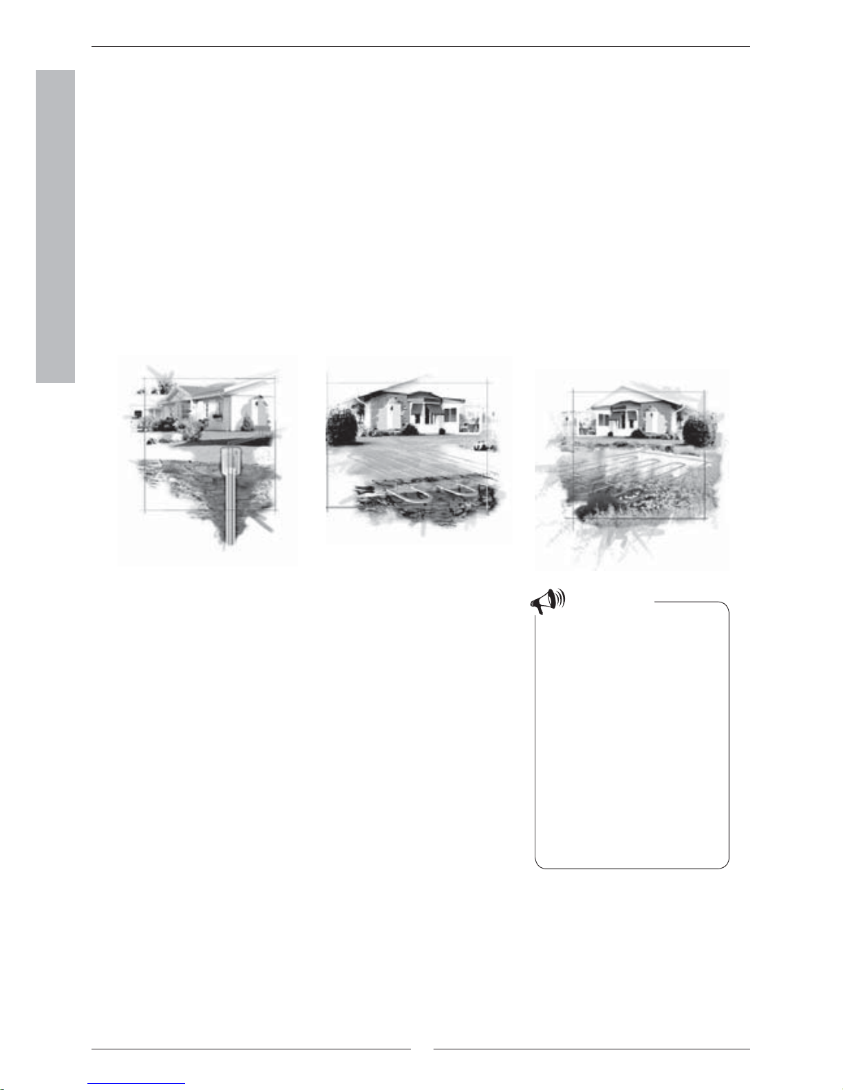
the ground, rock or water, is moved into the house. The heat pump collects a few degrees of the stored solar energy. The
heat is led into the house via a hose. The temperature is then increased in the heat pump and the heat is distributed to the
house’s heating system.
The heat pump collects stored solar energy
Boiling point in relation to the
pressure:
The boiling point of different liquids
varies with pressure, the higher the
pressure, the higher the boiling point.
For example, water boils at +100ºC
at normal pressure. Double the pressure and water boils at +120ºC. Half
the pressure and water then boils at
+80ºC. The refrigerant in the heat
pump acts in the same way, the boiling point changes when the pressure
changes. However, the boiling point of
the refrigerant is as low as approximately -40ºC at atmospheric pressure.
Consequently, it is also suitable for
low heat source temperatures.
Note
Rock heat Soil heat Lake heat
The heat pump consists of four main parts:
1. Evaporator
The evaporator evaporates the refrigerant to gas and transfers heat
from the heat transfer fl uid to the refrigerant circuit.
2. Condenser
The condenser condenses the vapour to fl uid again and transfers the
heat to the heating system.
3. Expansion valve
Lowers the pressure of the refrigerant.
4. Compressor
The compressor increases the pressure of the refrigerant.
These four main parts are linked in three circuits. A refrigerant circulates
in the heat pump, which in some parts of the circuit is in a liquid state and
in other parts in a gas state. Read more about the properties of the refrigerant in the sidebar to the right.
See the detailed description of the technologies used in the heat pump on
the next page.
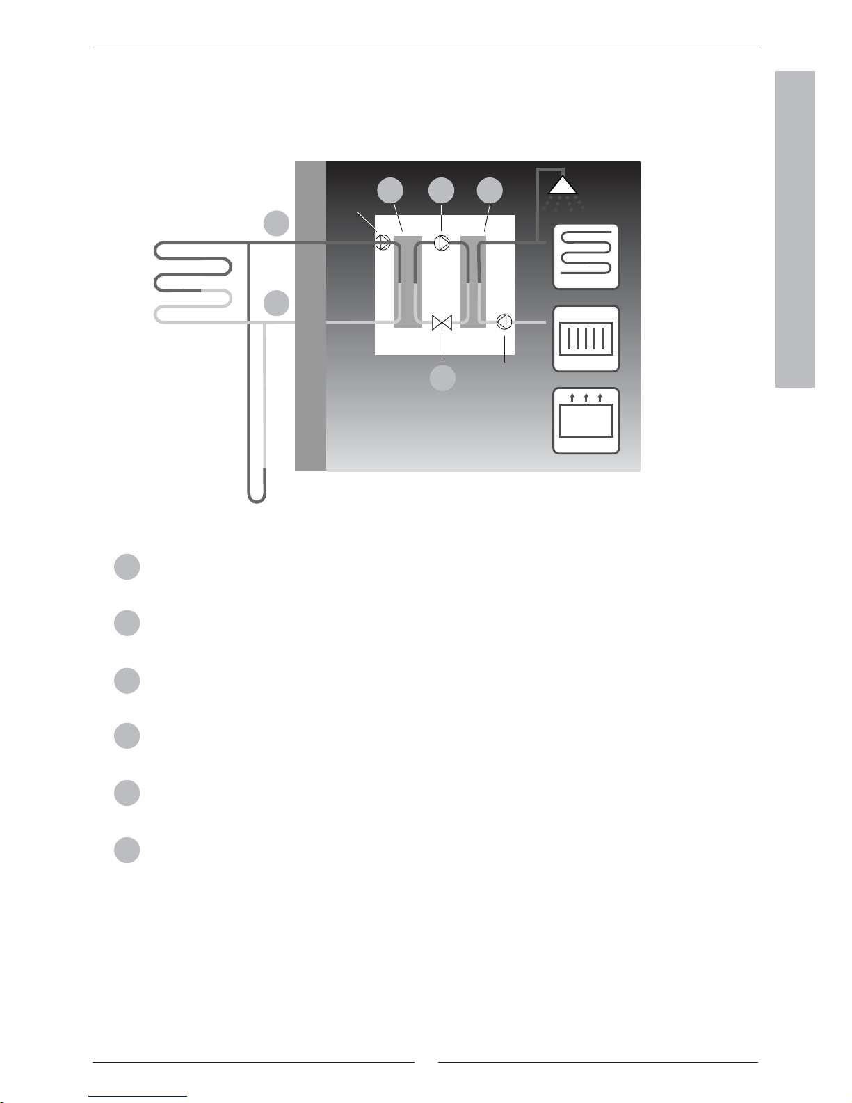
Technology in and around the heat pump
This is how your heat pump works
7
FOR THE USER
Heat transfer fl uid in. The heat pump collects stored solar energy. It contains a heat transfer fl uid which is a
solution of water and antifreeze, glycol. The antifreeze mixture collects the heat from the rock and with the
help of the heat transfer fl uid it is led into the evaporator. The temperature is then approximately 0ºC.
In the evaporator, the heat transfer fl uid meets the refrigerant. At this stage, the refrigerant is in a fl uid state
and is at approximately -10ºC. When the refrigerant meets the zero degree heat transfer fl uid it star ts to boil.
It then forms a vapour, which is led into the compressor. The temperature of the vapour is 0ºC.
The pressure of the refrigerant increases in the compressor and the vapour temperature rises from 0ºC to
approximately +100ºC. The warm gas is then forced into the condenser.
The condenser transfers the heat to the house’s heating system (radiators and fl oor heating) and the hot
water system. The vapour is cooled in the condenser and becomes fl uid. The pressure in the refrigerant is still
high when it is led on to the expansion valve.
The refrigerant pressure is lowered in the expansion valve. At the same time, the temperature also drops to
approximately -10ºC. When the refrigerant passes the valve and the evaporator it changes to vapour again.
There is also a valve for regulating refrigerant fl ow.
The heat transfer fl uid is led out from the heat pump to the rock to collect new stored solar energy. The heat
transfer fl uid is led out from the heat pump to the rock to collect new stored solar energy. The temperature of
the fl uid is approximately -3ºC.
1
2
3
4
5
6
Floor heating
Radiator
Fan-assisted
radiator
Heat pump
Rock
Soil
0ºC
-3ºC
0ºC +100ºC
-10ºC
1
6
2 3 4
5
Circulation pump
Heat transfer fl uid
pump
This is how your heat pump works
“The hot side”
“The cold side”
8
FOR THE USER
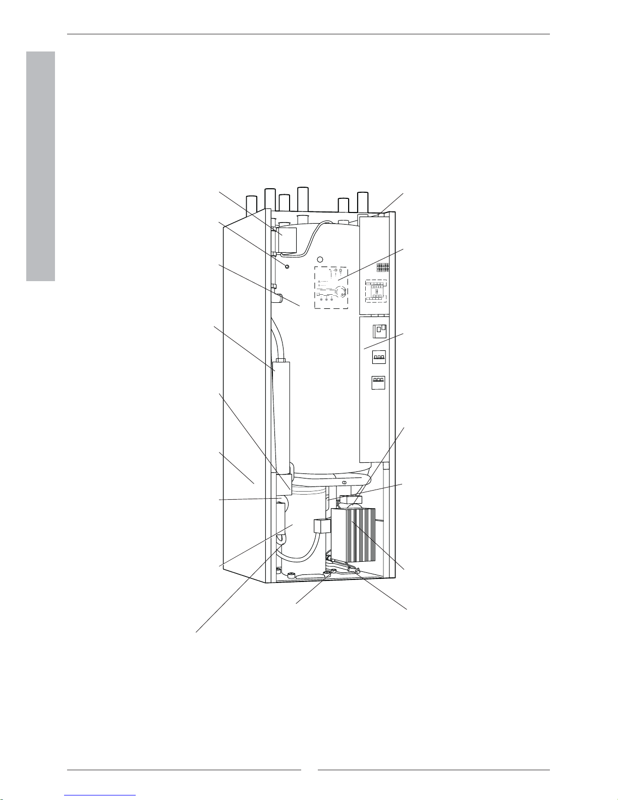
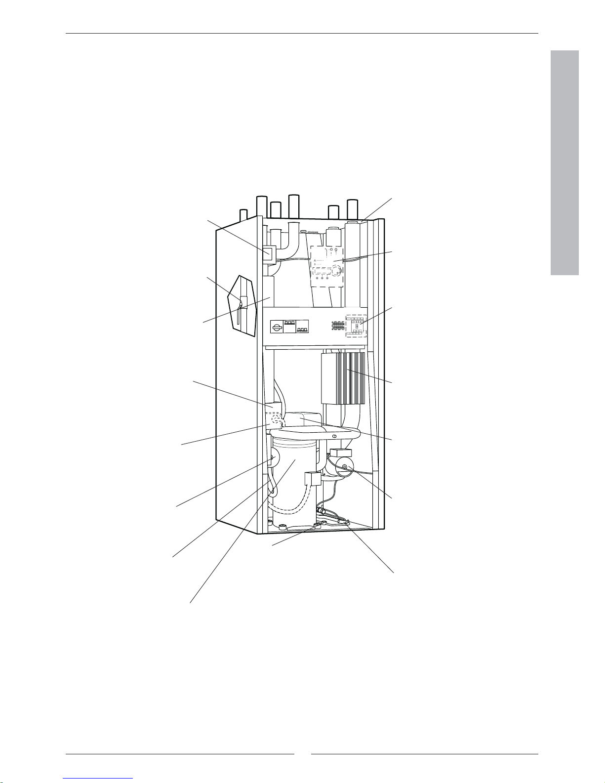
Component parts of the heat pump
Three-way valve
The valve switches between heating
the heating water and hot water.
Hot water cylinder
The cylinder is double-shelled and
holds approximately 163 litres of hot
water and 57 litres of the heating
water.
Electric cassette
The electric cassette is used to
provide extra output in cold weather
conditions, with large water consumption and at hot water peaks.
Reset button
Press in the button if the overheat
protector on the electric cassette has
tripped. The button is located on the
side.
Circulation pump
The pump ensures the heating water
circulates within the heating system.
Compressor
The compressor increases the
pressure of the refrigerant. The
temperature of the vapour increases
from 0ºC to approximately +100ºC.
The compressor is insulated to
reduce the noise level.
Electrical connections
Connections for the mains supply
as well as sensors.
Control panel
The control panel has a background lit menu display with four
rows of text information, three
buttons and a dial.
Distribution box
The distribution box is enclosed.
It houses a reset function for the
motor cut-out as well as miniature
circuit breakers (MCB) for the
heat pump and electric cassette.
Heat transfer fl uid pump
The pump is insulated and
features an anti-corrosive fi nish.
It ensures the heat transfer fl uid
circulates from, e.g. the rock to
the heat pump.
Control unit
The control unit is enclosed. It
controls and monitors all heat
pump functions.
Expansion valve
Lowers the pressure of the refrigerant that enters the evaporator
and collects energy from, e.g. the
rock.
Sight glass
Sight glass to check the level in the refrigerant circuit. Air bubbles must not form
in the sight glass when the heat pump is
running. However, there might be bubbles
when the heat pump is started and stopped.
Flexible hoses
The hoses counteract vibrations in
the heat pump.
LWM model
Evaporator
The evaporator evaporates the
refrigerant to gas and transfers
heat from the heat transfer fl uid to
the refrigerant circuit.
Condenser (not visable)
The condenser condenses the
vapour to fl uid again and transfers
the heat to the heating system.
Component parts of the heat pump
Venting nipple
The nipple is used to vent the heating
water in the hot water cylinder.
9
FOR THE USER
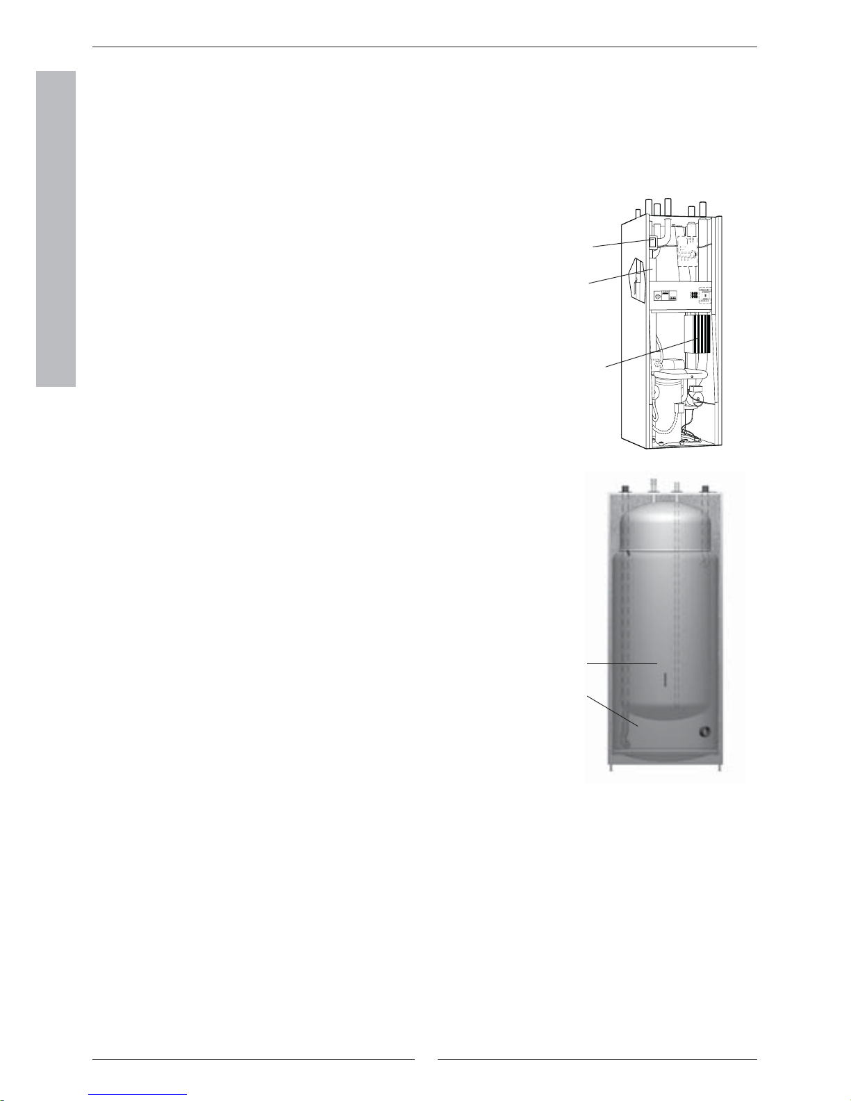
LW model
Reset button
Press in the button if the overheat
protector on the electric cassette
has tripped. The button is located
on the side.
Circulation pump
The pump ensures the heating
water circulates within the heating
system.
Compressor
The compressor increases the
pressure of the refrigerant.
The temperature of the vapour
increases from 0ºC to approximately +100ºC. The compressor is
insulated to reduce the noise level.
Electrical connections
Connections for the mains supply
as well as sensors.
Control panel
The control panel has a background lit menu display with four
rows of text information, three
buttons and a dial.
Distribution box
The distribution box is enclosed.
It houses a reset function for the
motor cut-out as well as miniature
circuit breakers (MCB) for the
heat pump and electric cassette.
Heat transfer fl uid pump
The pump is insulated and features
an anti-corrosive fi nish. It ensures
the heat transfer fl uid circulates
from, e.g. the rock to the heat
pump.
Control unit
The control unit is enclosed. It
controls and monitors all heat
pump functions.
Expansion valve
Lowers the pressure of the
refrigerant that enters the evaporator and collects energy from, e.g.
the rock.
Sight glass
Sight glass to check the level in the
refrigerant circuit. Air bubbles must
not form in the sight glass when the
heat pump is running. However, there
might be bubbles when the heat
pump is started and stopped.
Flexible hoses
The hoses counteract vibrations in the heat pump.
Evaporator
The evaporator evaporates the
refrigerant to gas and transfers
heat from the heat transfer fl uid to
the refrigerant circuit.
Particle fi lter
The fi lter can be opened for easy
cleaning. It also has a shut off
function.
Electric cassette
The electric cassette is used
to provide extra output in cold
weather conditions, with large
water consumption and at hot
water peaks.
Three-way valve
The valve switches between
heating the heating water and hot
water.
Condenser
The condenser condenses the
vapour to fl uid again and transfers
the heat to the heating system.
Component parts of the heat pump
10
FOR THE USER
Control unit
The control unit is the brains of the heat pump. It makes sure the heat
pump gives the best energy savings and that it runs for many years. The
control unit controls and monitors the heating and hot water supply in your
house. The monitoring function is especially important. It shuts down the
heat pump in the event of operational disturbances so that no critical parts
are damaged.
Additional heat gives more output
When the heat pump can not manage to heat the house by itself, for
example, if there is a considerable drop in the outdoor temperature, the
control unit ensures the additional heat source is connected. Together
the heat pump and additional heat guarantee the right temperature in the
house. Additional heat is provided by a built in electric cassette. Additional
heat can never completely take over the heating from the heat pump. It
only adds the output necessary for the heat pump to be able to produce the
right temperature. When the heat pump can once again manage heating on
its own the additional heat is automatically disconnected.
Hot water is given priority over heating water
In a house with water based heating a difference is made between heating
water and hot water. The heating water is for radiators/fl oor heating and
hot water is for showers and taps. Hot water is heated in a hot water heater.
The hot water heater is fi tted with a sensor that senses the temperature of
the hot water. LWM models include a hot water heater in the heat pump
while LW models have an external hot water heater. The heating water
passes through the hot water cylinder’s outer shell and heats up the hot
water heater’s inner tank. The control unit makes sure the heating of hot
water is always given priority over the heating of the heating water. This
means you never need to be without hot water. The control unit controls a
three-way valve that switches between heating the heating water and hot
water. Once the hot water has been heated the three-way valve switches so
that the heating water is heated.
Control unit
Electric cassette
(additional heat)
Three-way
valve
Double-shelled hot water heater
Heating water
Hot water
Control unit

11
FOR THE USER
The control unit’s two methods to control
the heat pump
The control unit uses two different methods to control the heat pump.
These two methods are: Control with an outdoor sensor and Control with
an outdoor sensor supplemented with a room sensor.
Control with outdoor sensor
Control with an outdoor sensor is the most common method used by the
control unit to control the heat pump. A sensor is installed on the external
wall of the house. It sends out signals for regulating the heat pump. Control
with an outdoor sensor means that the heat pump automatically regulates
the heating in the house depending on the outdoor temperature. If the
outdoor temperature drops, i.e. it becomes colder; the radiators inside the
house will become warmer.
You determine the temperature of the radiators, in relation to the outdoor
temperature, with the help of a number of settings such as selecting the
heat curve on the control unit. A lower curve gives higher energy savings.
Control with outdoor sensor supplemented with
room sensor
Control with an outdoor sensor supplemented with a room sensor means
that you also place a sensor in a central position inside the house. This is
connected to the heat pump and provides the control unit with information
about the room temperature. The signals affect the control unit’s settings
(curves) and ensure the heat pump gives the best possible energy savings.
This control method is used when factors other than the outdoor temperature infl uence the indoor temperature. Examples include the use of a stove
or fan-assisted radiator or if the house is sensitive to the wind.
It is only the room where the room
sensor is located that can infl uence
regulation of the temperature.
Note
Control unit
Note
The room sensor infl uence is inhibited
24 hours after using clock setting for
the heating, or any type of external
control of the heat pump.
12
FOR THE USER
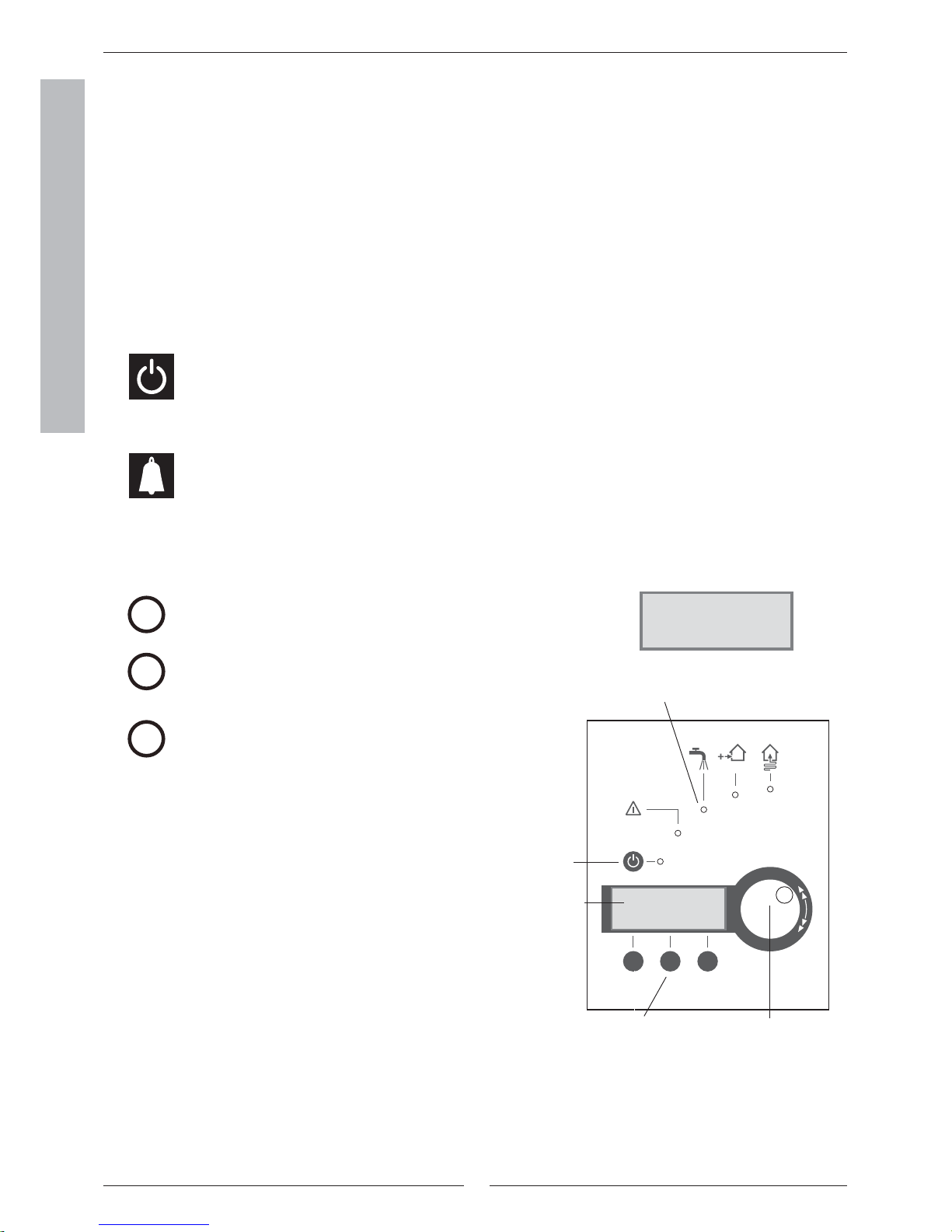
Control panel
All settings are made from the control panel. It also displays heat production
statistics and information about different alarms. When you have made your
settings, the control panel makes sure they are saved in the control unit to
carr y out your wishes.
Menu dial
Controls and status lamps
Power switch (ON/OFF)
You start and stop the heat pump using the power
switch button.
Lamp on: The heat pump is on.
Lamp fl ashes: The heat pump is off.
Alarm status
Lamp fl ashes: A fault has occurred in the heat
pump.
Lamp on: The alarm has been acknowledged, but
the fault remains.
Temp. incr. /
decr.
Temp. incr. / decr.
Pressing once gives a shortcut to the most frequent
temperature settings.
Info
Pressing once gives continuous information about the
heat pump’s and additional heat’s operating conditions.
Menu
Press once to enter the main menu.
The main menu contains all setting menus and
temperature displays.
Info
Menu
Control panel
Reg 637 K1
040622 16:08:15 Tu
temp. Info Menu
Menu buttons
Rego 637 K1
040622 16:08:15 Ma
temp. Info Menu
Menu display
Power switch
(ON/OFF)
Status lamps
13
FOR THE USER
Control panel
Reg 637 K1
040622 16:08:15 Tu
temp. Info Menu
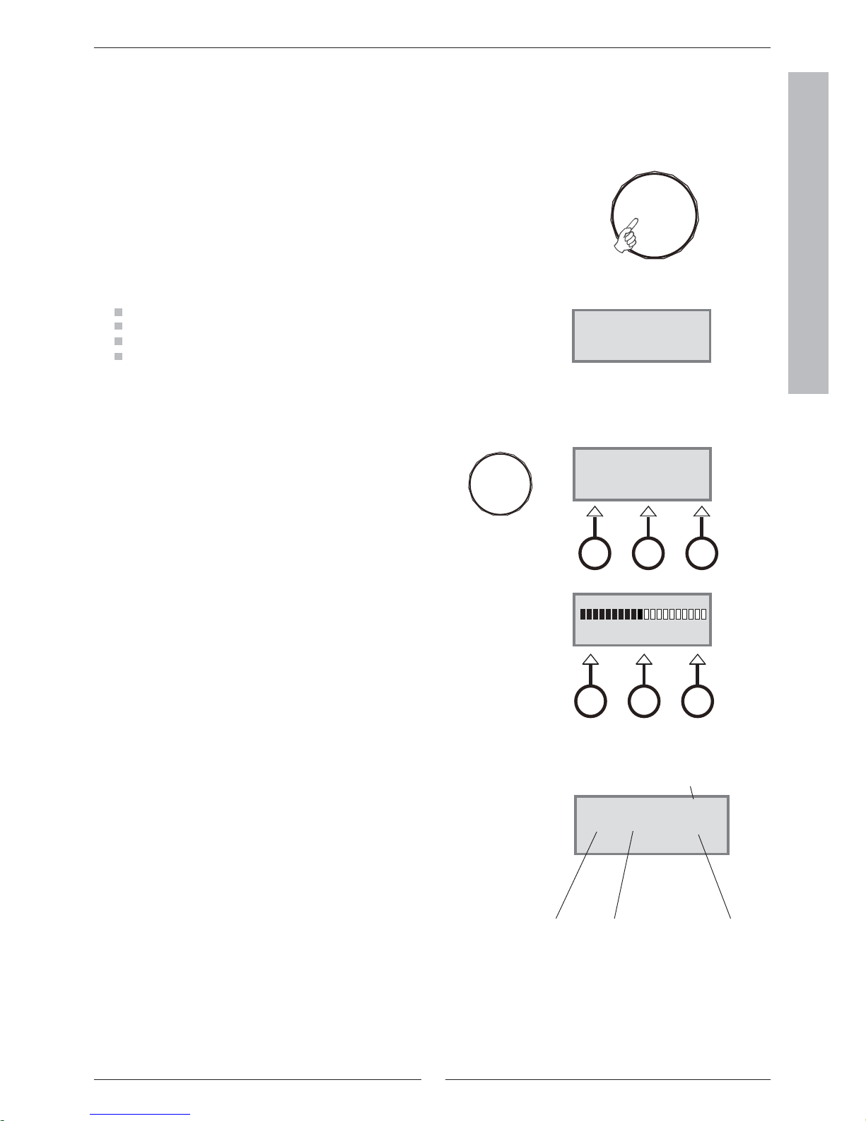
Menu dial
The menu dial is used to scroll through the menu display windows. Turn the
menu dial clockwise (to the right) to move down through the menus. Turn the
menu dial anti-clockwise (to the left) to move up through the menus. You also
determine the values of different settings by using the dial.
The menu display gives you information and the chance to make settings. You
can:
Choose different temperature and hot water settings.
Choose extra hot water and the holiday function.
See alarm causes and receive corrective instructions.
Obtain operating statistics.
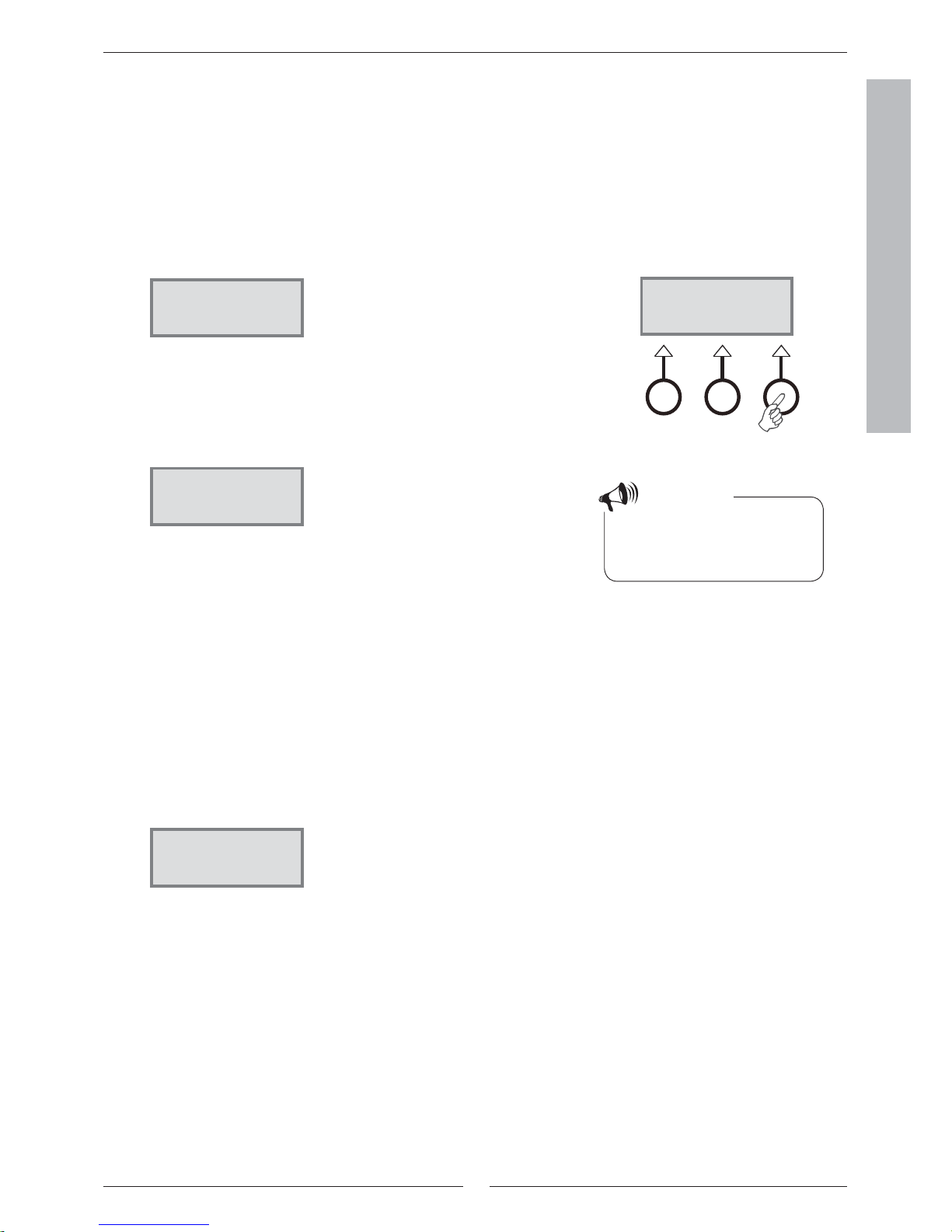
How to use the control panel
The principle of the control panel is based on the user using three
menu buttons and a menu dial to move between the different
menus and settings. On the lower row of the menu display you will
always see information about the signifi cance of the buttons. The
function of the buttons changes depending on which window you
are currently in.
Example
If, from the initial menu, you press the Heat button, you will access
the menu Temp. incr. / decr.. +/-. In this menu you can increase and
decrease the heating in the house. Note that the signifi cance of the
buttons has now changed. You can either return to the initial menu
by pressing the Return button or you can choose to change the
heating setting in the house by pressing the Adjust button. If you
press the Adjust button you can increase or decrease the heating in
the house by using the menu dial. Save your adjustment by pressing
the Save button.
Initial menu display
+
Initial menu
Time Date
Customer level 1
Day
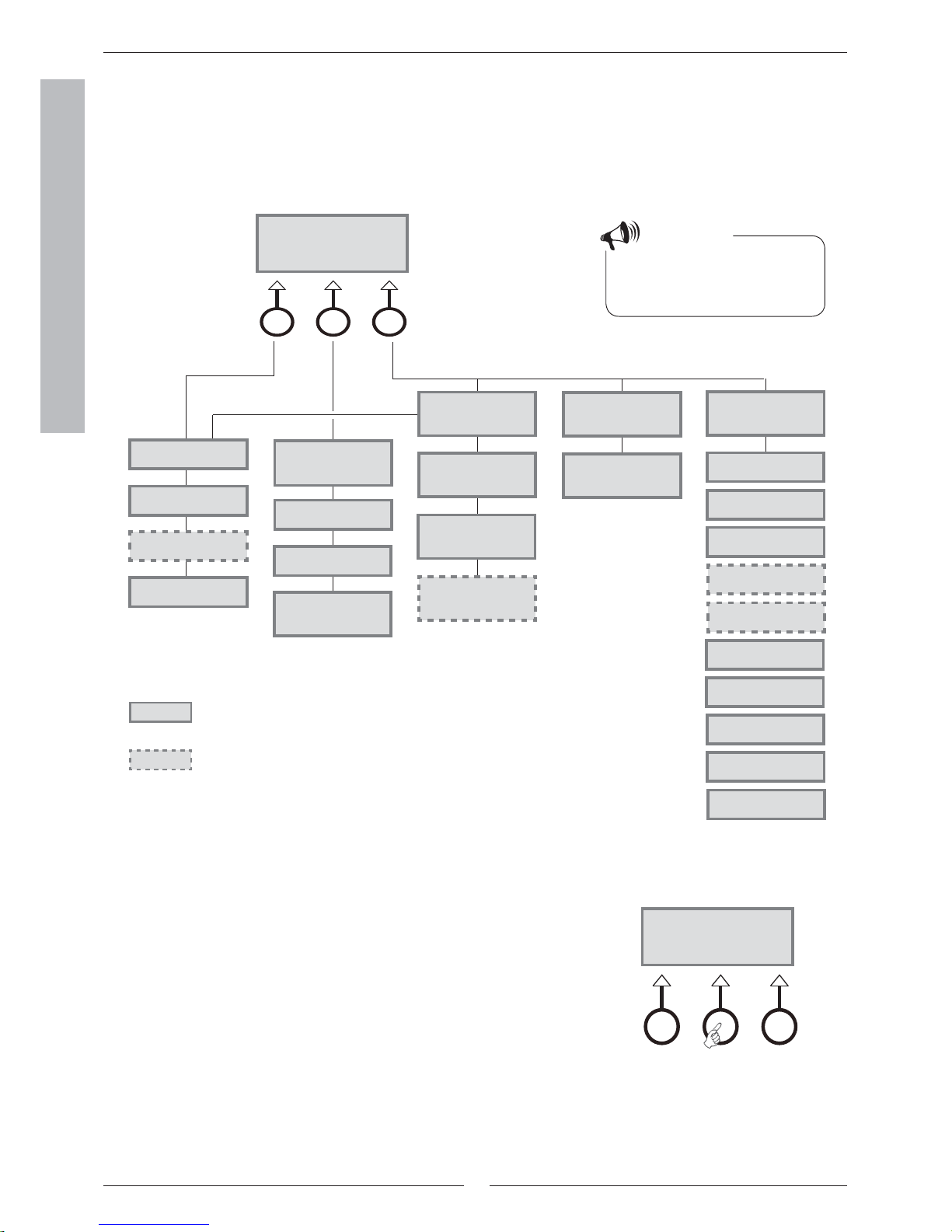
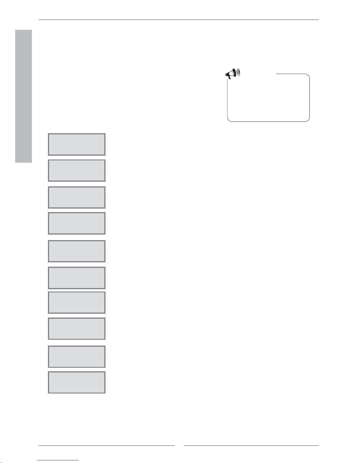
Basic functions ( Customer level 1)
Basic functions (Customer level 1) are the functions most frequently used
and the ones you have the most benefi t of. You reach the basic functions
by pressing one of the Heat, Info or Menu buttons in the initial menu. The
designation K1 in the upper right corner indicates you are in Basic functions
- Customer level 1.
Reg 637 K1
040622 16:08:15 Tu
Temp. Info Menu
Reg 637 K1
040622 16:08:15 Tu
Temp. Info Menu
temp. +/-
0 5,0 10
Return Adjust
14
FOR THE USER
Basic functions - Customer level 1
The menu display is standard on all
heat pumps.
=
=
Temp. Fine-tune
Page 17
The menu display is only shown on
the heat pump in combination with an
extra sensor or for a specifi c model.
temp. +/-
Page 16
Room temperature
Page 18
Extra hotwater
Page 18
STANDBY
no rad heat required
No need
for hot water mode
Page 15
HOT WATER MODE
Heat pump only
Page 15
HEATING Mode
HP and add. heat
Page 15
Heat rad required
Heat pump starts
in #### seconds
Page 15
Main menu
Indoor temperature
settings 1
Page 19
Temperature settings
Temp. incr. / decr.
range 0-10 1.1
Page 16
Temp. settings
Adjust temp.
range -10/+10 1.2
Page 17
Temp. settings
Int. temp 1.10
Page 18
Main menu
Adjusting the hot
water settings 2
Page 19
Hot water setting
Duration of
add. hot water 2.1
Page 18
Main menu
Monitor all
temperatures 3
Page 19
Temperature readings
Return radiator GT1
Temperature readings
Out GT2
Temperature readings
Hot water GT3
Temperature readings
Shunt, fl ow GT4
Temperature readings
Room GT5
Temperature readings
Compressor GT6
Temperature readings
Heat trfl uid out GT8
Temperature readings
Heat tr fl uid in GT9
Temperature readings
Ht trfl d(coll)inGT10
Temperature readings
Httrfl d(coll)out GT11
Page 20
Note
Each menu is numbered in the lower
right-hand corner; this indicates which
main display it is associated to.
Select scrolling information on the menu display
If you press the Info button in the initial menu, you will receive continuous
information about the heat pump’s operation and working temperatures.
This is what to do:
1. Press the Info button in the initial menu.
Here follows a few of the windows displayed:
Menu outline for Basic functions (Customer level 1)
Reg 637 K1
040622 16:08:15 Tu
temp. Info Menu
Reg 637 K1
040622 16:08:15 Tu
temp. Info Menu

15
FOR THE USER
The heat pump is in standby mode.
The heat pump is producing hot water. You see at which temperature
the heat pump will stop and the present temperature. Note that the stop
temperature is read at the bottom of the heater. The hot water is a few
degrees warmer.
The heat pump and additional heat are running.
The heat pump has received signals that it should produce heating. It now
waits for the restart time to countdown to zero.
Return to the initial menu by pressing one of the buttons or turn the dial.
Basic functions - Customer level 1
Set the heating
It is easy to set the heating level on the heat pump. However, before we
explaaccord. to clockow to do this it is important to understand the relation
between the outdoor temperature, return temperature and heat curve
slope. The easiest way to explain the relation is with a heat curve.
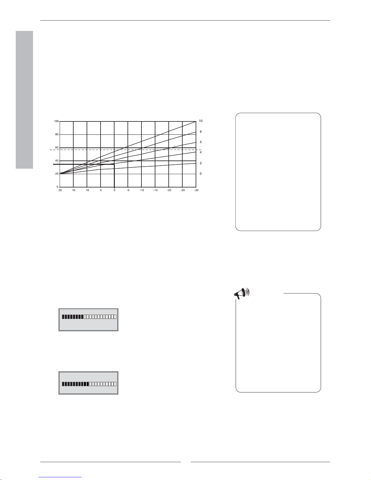
Heat curve
You use the heat curve to help set the indoor temperature you would
like. The heat pump is controlled by the outdoor temperature. When the
weather becomes colder, the heat pump ensures more heating is produced
automatically.
Return temperature:
The return temperature is the temperature of the water that returns to the
heat pump from the radiators. The water led out from the heat pump to the
heating system is normally 7-10ºC higher than the return temperature.
When the outdoor temperature is -10ºC and curve 4 is set, the pump
attempts to keep the return water at approximately 40ºC.
Outdoor temperature:
The outdoor temperature determines how much heating the heat pump
should produce. A sensor placed outdoors sends signals to the control unit,
which then adjusts the heat pump.
Cur ve slope:
You can change the curve slope to increase or decrease the heating in the
house. The scale is between 0-10.
On delivery the heat pump cur ve
slope is set to position 4. This means
that the return temperature is +35ºC
when it is 0ºC outdoors.
Note
STANDBY
No rad heat required
No need
for hot water mode
Heat rad required
Heat pump starts
in 320 seconds
HOTWATER MODE
Heat pump only
Supp. temp. 53,0°
Present temp 42.0°
HEATING Mode
HP and add. heat
Supp. temp. 45,0°
Present temp 44.0°
16
FOR THE USER
In cold weather (below +5ºC):
If you are not satisfi ed with the indoor temperature when it is colder than +5ºC
outdoors, you need to change the slope of the heat curve.
This is what to do:
1. Press the Heat button in the initial menu.
2. Press the Adjust button.
3. Turn the menu dial clockwise to increase the heating.
Turn the menu dial anti-clockwise to lower the heating.
(Adjust in small increments, 0.2-0.6 units, is usually enough.)
4. Save the new value by pressing the Save button.
Basic functions - Customer level 1
Dashed line:
If the return temperature exceeds 57ºC an alarm is given and the compressor switches off. The heat pump star ts automatically when the return
temperature drops.
Curve slope:
2-4 Normal setting for fl oor heating..
4-6.5 Normal setting for radiators.
7-10 Abnormal high setting.
From the heat curve we see that
curve slope 4 gives a return temperature of +35ºC when it is 0ºC outdoors.
If the outdoor temperature drops we
can see that the return temperature
increases. The colder the outdoor
temperature the higher the return
temperature. At an outdoor temperature of approximately -30ºC we see
the curve slope has nearly reached
the limit value (+57ºC) for the return
temperature.
You should wait at least two days
when increasing or decreasing the
heating before making a new adjustment.
If it is still diffi cult to get a comfortable indoor temperature at an outdoor
temperature around 0ºC, despite
several attempts, you should adapt
the heat curve. Read about how
to “adapt the curve” in the section
Extra functions – Customer level 2 /
Temperature settings / Adapting the
heat curve.
Note
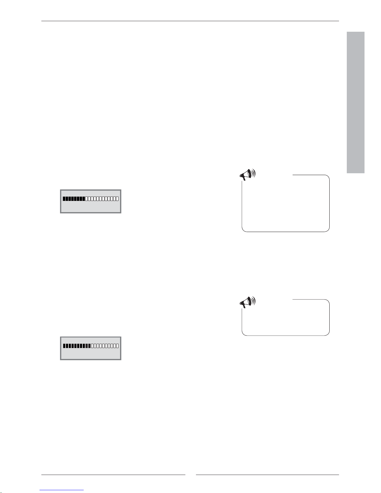
Change the curve slope
The heat pump’s production of heat is adjusted by increasing or decreasing
the curve slope in the Temp. incr. / decr. menu. This is especially ef fective
in cold weather conditions.
Return temperature (ºC) Curve slope (0-10)
Outdoor temperature (ºC)
temp. +/-
0 4,0 10
Return Adjust
temp. +/-
0 5,0 10
Return Save
17
FOR THE USER
Basic functions - Customer level 1
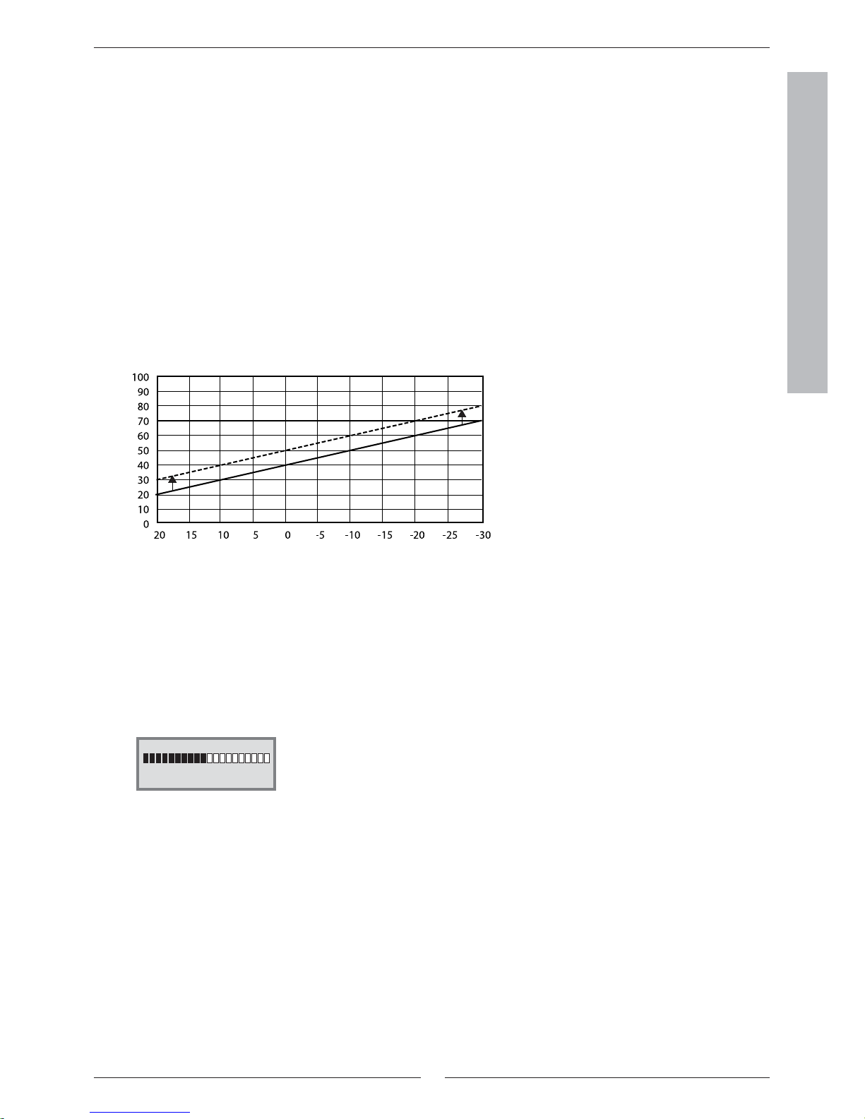
Fine-tune the heat curve
The heat curve can also be fi ne-tuned. Fine-tuning means that you offset
the heat curve in parallel. Fine-tuning is done from the Temp. fi ne-tune
menu. The diagram for fi ne-tuning shows how the dashed line has been
offset upwards in parallel. This means the heating has been fi ne-tuned in a
positive direction and the heat pump will be instructed to maintain a higher
temperature on the return water at all outdoor temperatures.
Outdoor temperature (ºC)
Return temperature (ºC)
By using the menu dial on the control panel
the fi ne-tuning line has been moved up so the
heat pump produces more heat.
In warm weather (above +5ºC):
If you are not satisfi ed with the indoor temperature when it is warmer than
+5ºC outdoors, you should offset the cur ve in the Temp. fi ne-tune menu.
This is what to do:
1. Press the Heat button in the initial menu.
2. Turn the menu dial clockwise until you reach the menu Temp. fi netune.3.
3. Press the Adjust button.
4. Turn the menu dial clockwise to increase the room temperature. Turn
the menu dial anti-clockwise to lower the room temperature. (Adjust in
small increments, 0.2-0.6 units, is usually enough.)
5. Save the new value by pressing the Save button.
Temp. Fine-tune menu
-10° 0,0 10°
Return Adjust
18
FOR THE USER
Set the desired room temperature
If you have a room sensor connected to the heat pump you can set the required
temperature in the room from the Room temperature menu. From Extra
functions (Customer level 2) you can also set how much you want the sensor to
infl uence the heating system.
This is what to do:
1. Press the Heat button in the initial menu.
2. Turn the menu dial clockwise until you reach the menu Room temperature.
3. Press the Adjust button.
4. Turn the menu dial clockwise to increase the room temperature. Turn the
menu dial anti-clockwise to lower the room temperature.
5. Save the new value by pressing the Save button.
Note
The example describes how to set the
required room temperature with the
help of a connected room sensor. The
range is 10ºC to 30ºC.
Set the heat pump for extra hot water
You can obtain extra hot water by temporarily increasing the temperature
of the water in the hot water cylinder. This may be appropriate when, for
example, a large number of people need to shower. You choose how long
the function should run using the Extra hotwater menu. . This is what to
do:
1. Press the Heat button in the initial menu.
2. Turn the menu dial clockwise until you reach the menu Extra
hotwater.3. .
3. Press the Adjust button.
4. Turn the menu dial clockwise to choose the number of hours that the
electric cassette should be on (e.g. 24 hours).
5. Save the new value by pressing the Save button.
When the set time has elapsed you
must repeat the setting to get extra
hot water again.
Note
Basic functions - Customer level 1
Add. hot water
1h 24h 48h
Return adjust
Add. hot water
1h 24h 48h
Return Save
Room temperature
10° 20,0 30°
Return adjust
19
FOR THE USER
Basic functions - Customer level 1
Heating and hot water settings
Move to the temperature settings for heating on Customer level 1 like this:
1. Press the Menu button in the initial menu.
2. Press the Select button and scroll through the heating menus with the
menu dial.
Move to the temperature settings for hot water on Customer level 1 like this:
1. Turn the menu dial clockwise until you reach the menu Adjusting the
hot water settings .
2. Press the Select button and scroll through the hot water menus with
the menu dial.
Read the temperatures on the heat pump
There are several different temperature sensors in the heat pump. Each
sensor plays an important par t in the heat pump’s daily operations. It may,
for example, adjust the heat production so that the pump does not become
overheated. Proceed as follows to read the temperatures on the heat pump:
1. Press the Menu button in the initial menu.
2. Turn the menu dial clockwise until you reach the menu Monitor all
temperatures (menu 3).
3. Press the Select button.
4. Turn the menu dial to scroll through all the heat pump’s temperature
sensors. See the next page.
Note
Each menu is numbered in the lower
right-hand corner; this indicates which
main display it is associated to.
Reg 637 K1
040622 16:08:15 Tu
temp. Info Menu
Main menu
Indoor temperature
settings 1
Return Select
Main menu
Adjusting the hot
water settings 2
Return Select
Main menu
Monitor all temp.
on the screen 3
Return Select
20
FOR THE USER
All menus relating to temperature sensors
All the menus associated with the heat pump temperature sensors are shown
below. Note that you cannot make any settings in these menus, only read the
current values. Some menus are standard for all models of Ecolane SE while
others are only available in combination with different accessories.
The sensors give an alarm if the temperature is outside of the permitted
range/values.
Note
All sensors are not included as
standard on the heat pump, some are
available as accessories for different
application areas. See more information under respective menus.
The menu shows the temperature in the heating system’s return, i.e. the water from the
radiators back to the heat pump accord. to clockeating mode. The temperature varies with
the outdoor temperature.
The menu shows the outdoor temperature. Some deviation compared to the true temperature may occur due to thermal radiation from the house to the installed outdoor sensor.
The menu shows the set and present temperature in the lower section of the outer
container in the hot water heater. The temperature is approximately 5ºC lower than the
temperature of the hot water inside the inner container.
The menu only applies together with a fl ow sensor. If an extra curve with mixing valve
is used, for example, for a fl oor heating system, you can see the temperature on the fl ow
water in the circuit. The temperature varies with the outdoor temperature.
The menu only applies together with a room sensor. The menu shows the set point value
and present temperature in the room where the sensor is fi tted.
The menu shows the compressor’s working temperature. The temperature varies
between 70ºC and 125ºC during operations.
The menu shows the temperature of the radiator water as it leaves the heat pump. It
varies depending on the outdoor temperature and whether the heat pump is accord. to
clockot water production mode.
The menu shows the temperature of the water that is led into the heat pump. It varies
depending on the outdoor temperature and whether the heat pump is accord. to clockot
water production mode. The heat pump stops at 57ºC for reasons of safety.
The menu shows the temperature of the heat transfer fl uid that is led into the heat pump
from the bore hole or the ground. It can vary between -5ºC to +15ºC during a season.
The menu shows the temperature of the heat transfer fl uid that is led out of the heat
pump to the bore hole or the ground. Normally, during operations, it is 1.5 - 5.0 degrees
lower than the heat transfer fl uid that is led into the heat pump.
Basic functions - Customer level 1
Temperature readings
Return radiator GT1
Off 41.3
O
now 40.3
O
Return
Temperature readings
Out GT2
14,0°
Return
Temperature readings
Hot water GT3
Set 51.0° now 50.0°
Return
Temperature readings
Shunt, fl ow GT4
Set 40.3° now 43.0°
Return
Temperature readings
Room GT5
Set 20.0° now 19.5°
Return
Temperature readings
Compressor GT6
90,0°
Return
Temperature readings
Heat tr fl uid out GT8
45,0°
Return
Temperature readings
Heat tr fl uid in GT9
40,3°
Return
Temperature readings
Ht trfl d(coll)inGT10
0,0°
Return
Temperature readings
Httrfl d(coll)outGT11
-4,0°
Return

21
FOR THE USER
Extra functions - Customer level 2
Extra functions (Customer level 2)
The section Basic functions (Customer level 1) contains the functions that you will
probably use the most and which you will receive the most benefi t from. However,
there are numerous extra functions that you can use to control your heat pump.
This can, for example, include activating the heat pump’s holiday function or
setting the time and date. If no settings are made on Customer level 2 (K2), the
menu display will automatically return to Customer level 1 (K1) after 30 minutes.
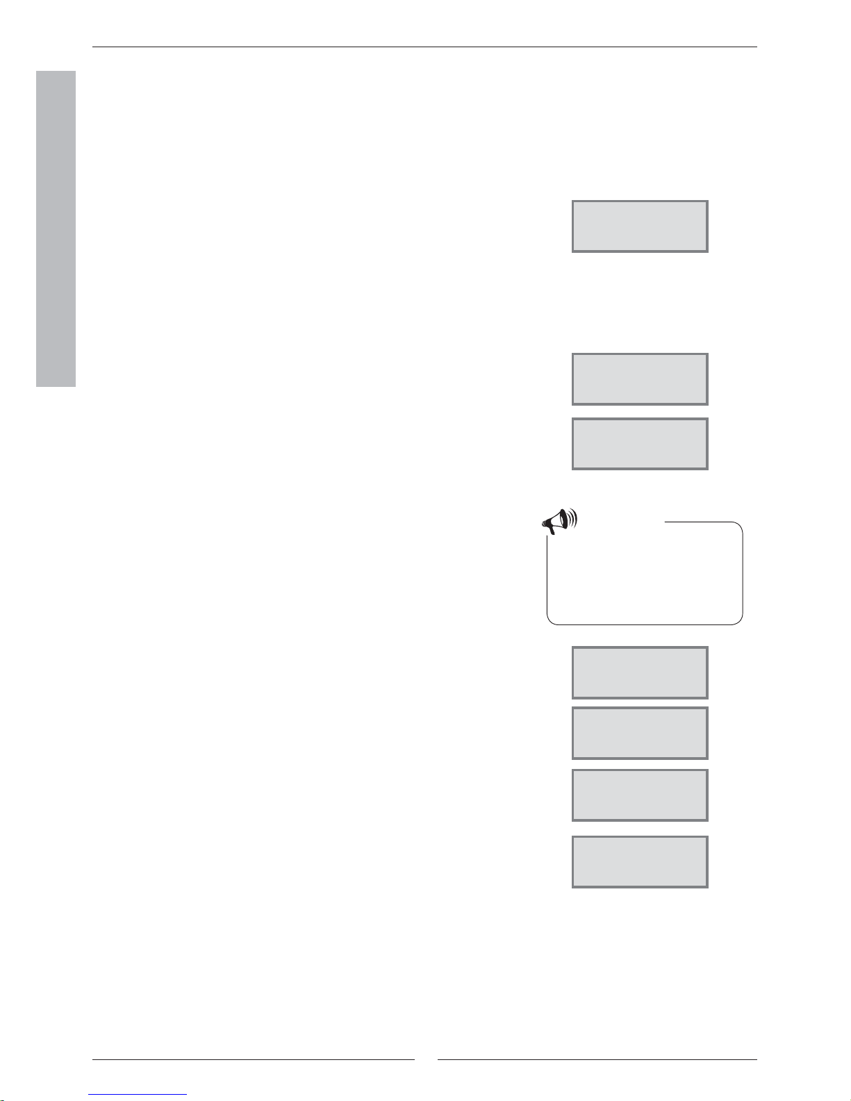
Proceed as follows to access the extra functions on Customer level 2:
1. Press the Heat button until Access = CUSTOMER2 is displayed.
2. Press the Menu button to open the Main menu. From Customer level 2 you
also have access to all Customer level 1 functions.
Note
From Customer level 2 you also have
access to all the basic functions on
Customer level 1.
Only the most frequently used menus
in Customer level 2 are shown in the
menu outline. All the menus cannot be
presented due to space limitations. Use
the dial to scroll through the menus.
Press the Heat button until Access
= CUSTOMER2 is displayed.
( Initial menu)
The menu display is standard
on all heat pumps.
=
=
The menu display is only
shown on the heat pump in
combination with an extra
sensor or for a specifi c model.
Heat curve
fi ne-tuning 1.3
Page 22
Menu principal
Room temp. setting 1
Page 23
V3V +/interv. 0-10 1.5
Page 23
Adjust. V3V
range -10/+10 1.6
Page 23
Adjust curve
V3V 1.7
Page 23
Setting of room
sensor infl 1.11
Page 22
Setting of holiday
function 1.12
Page 22
Remote control
temperature 1.13
Page 22
Setting of summer
disconnection 1.14
Page 22
Main menu
Adjusting the hot
water settings 2
Page 24
interval for
hot water peak 2.2
Page 24
Main menu
Timer control
settings 4
Page 24
Clock setting HP
accord. to clock 4.1
Page 24
Setting level
heat pump +/- 4.1.1
Page 25
Clock setting DHW
accord. to clock 4.3
Page 25
Main menu
Op. time readings
HP and add. heat 7
Page 25
Add. heat in operat.
number of hours? 7.1
Page 26
Add. heat in operat.
number of hours? 7.3
Page 26
Main menu
Clock, setting
time and date 10
Page 27
Main menu
Alarm logging
of all alarms 11
Page 27
Main menu
Return to
factory settings 12
Page 27
Menu outline for Extra functions (Customer level 2)
Reg 637 K2
040622 16:08:15 Tu
temp. Info Menu
Reg 637 K2
040622 16:08:15 Tu
temp. Info Menu
Distribution HP
DHW-Rad in % 7.2
Page 26

22
FOR THE USER
Temperature settings
Proceed as follows to access the temperature settings for the heating on Customer
level 2:
1. Press the Heat button until Access = CUSTOMER2 is displayed.
2. Press the Menu button.
3. Press the Select button and scroll through the menus using the menu dial.
Fine-tune the heat curve
You can “break” the heat curve up or down every fi fth outdoor degree. For example,
you can make a hump in the curve at 0ºC. Navigate to menu 1.3, press Select and
turn the menu dial until 0°C is displayed in the upper left part of the menu. Press
Adjust and turn the dial to increase or decrease the return temperature. The change
must not exceed 1 - 2°C. Press Save and wait at least 24 hours prior to any further
adjustment. The purpose of breaking the curve is to be able to infl uence the heat
pump’s heat production at extra sensitive outdoor temperatures.
Room sensor infl uence
The menu is only shown for heat pumps having a room sensor installed. You use the
menu to set how much the room sensor should infl uence the heat curve. A higher
value will have a greater effect. Please note that the room sensor only fi ne-tunes the
heat curve. Consequently, it is important the basic setting of the heat curve’s slope
and fi ne-tuning are correct.
Holiday mode
The menu is only shown for heat pumps having a room sensor installed. The
holiday function gives you the possibility to choose a number of days when the
room temperature will be lowered to 15ºC (the temperature is not adjustable).
When the days have passed the heat pump returns to the normal heating setting.
Hot water production is not affected by the holiday function.
Remote control
The menu is only shown for heat pumps having a room sensor installed. In addition,
special remote control equipment is needed. This equipment is available as an
accessory. You can switch between the remote control mode and normal mode
using a telephone.
Summer disconnection
The function means the heat pump only produces hot water when the outdoor
temperature rises above the set value.
Extra functions - Customer level 2
Main menu
Indoor temperature
settings 1
Return Select
Temperature settings
Heat curve
fi ne-tuning 1.3
Return Select
Temperature settings
Setting of room
sensor infl 1.11
Return Select
Temperature settings
Setting of holiday
function 1.12
Return Select
Temperature settings
Remote control
temperature 1.13
Return Select
Temperature settings
Setting of summer
disconnection 1.14
Return Select
23
FOR THE USER
Set extra heat curve with mixing valve
If you have fl oor heating combined with radiators, you should set an extra heat
curve with mixing valve. The mixing valve is a valve that lets water through in
different amounts. It prevents the fl oor from becoming too hot and destroying
the fl ooring. The menu is only displayed when there is an extra fl ow sensor, T4
(GT4), on the heat pump. You set the extra heat curve using two menus: Mix.
valve incr/decr and Mix. valve fi ne-tune.
Increase or decrease the mixing valve
1. Press the Heat button until Access = CUSTOMER2 is displayed.
2. Press the Heat button.
3. Turn the menu dial clockwise until you reach the menu Mix. valve incr/
decr.4.
4. Press the Adjust button.
5. Turn the menu dial clockwise to choose a higher heat cur ve.
Turn the menu dial anti-clockwise to choose a lower heat curve.
6. Save the new value by pressing the Save button.
Note
The initial position of the fl oor heating circuit is heat curve 2.
The scale covers the range 0 to 10.
Extra heat curve with mixing valve
only works with an extra fl ow sensor
T4 (GT4).
Fine-tune the mixing valve
1. Press the Heat button until Access = CUSTOMER2 is displayed.
2. Press the Heat button.
3. Turn the menu dial clockwise until you reach the menu Mix. valve fi ne-tune.
4. Press the Adjust button.
5. Turn the menu dial clockwise to set an upward, parallel offset on the curve.
Turn the menu dial anti-clockwise to set a downward parallel offset on the
curve.
6. Save the new value by pressing the Save button.
Note
The example describes how to fi netune the extra heat curve. The scale
covers the range -10ºC to +10ºC.
Extra functions - Customer level 2
Mix. valve incr/decr
0 2,0 10
Return adjust
Fine tune mix. valve
-10° -0,0° 10°
Return adjust
24
FOR THE USER
Timer control
Open the setting menus for timer control like this:
1. Press the Heat button until Access = CUSTOMER2 is displayed.
2. Press the Menu button.
3. Turn the menu dial clockwise until you access the menu Timer control
settings (menu 4).
4. Press the Select button and scroll through the menus using the menu dial.
Clock setting of the heat pump according to clock
The function Clock setting HP accord. to clock is for those who want the heat
pump to produce different amounts of heat at different times of the day and
on different days of the week. This allows you to make further energy savings.
The room sensor T5 (GT5) infl uence is inhibited 24 hours after using clock
setting for the heating, or after any type of external control of the heat pump.
This allows the heating to return to ordinar y settings. In practise this means
that should clock setting of the heating apply each night, then the room sensor
has no function except temperature readings.
Example:
You want to set the heat pump so that it maintains a 3ºC lower radiator temperature on Mondays between 22:00 and 06:00.
1. Turn the dial clockwise until you access the menu Clock setting HP accord.
to clock (menu 4.1).
2. Press the Select button.
3. Turn the menu dial clockwise to choose the day. Now press the Adjust
button to select the weekday with the symbol ^. Turn the menu dial
clockwise one step to activate the start day. The weekday now has a capital
letter.
4. Press the right-hand arrow (->) until the cursor reaches the fi rst two zeros
(00).
Extra functions - Customer level 2
Hot water settings
Hot water peak
Recurring increase in the hot water temperature
The Range for hot water peak menu is used to set the range for a recurring
increase in the hot water temperature. This function takes the water temperature temporarily up to approximately 65°C. Three settings are possible:
inactive (default), daily or preferred day.
Hot water
range for
hot water peak 2.2
Return Select
Main menu
Indoor temperature
settings 1
Return Select
Main menu
Timer control
accord. to clock 4
Return Select
Clock setting
Clock setting HP
accord. to clock 4.1
Return Select
Timer control HP 1
Mon 00:00-00:00
Return adjust
>
Timer control HP 1
Mon 00:00-00:00
Return ->
>
Timer control HP 1
Mon 00:00-00:00
Return ->
>
>
Note
When you have time based tariffs
with cheaper electricity for example
during the night, any savings may be
lost if the return to normal temperature occurs when the more expensive electricity price applies.
 Loading...