

Bosch DSX‑N6D8X4‑60AT, DSX‑N6D8X8‑60AT, DSX‑N6D8XC‑60AT, DSX‑NRCK40‑INT8 Installation manual
DSA E‑Series (E2800 60‑bay)
DSA‑N6C8X4‑60AT | DSA‑N6C8X8‑60AT | DSA‑N6C8XC‑60AT |
DSX‑N6D8X4‑60AT | DSX‑N6D8X8‑60AT | DSX‑N6D8XC‑60AT |
DSX‑NRCK40‑INT8
en
Installation manual


DSA E-Series (E2800 60-bay) Table of contents | en 3
Table of contents
1
Safety 5
1.1 Safety message explanation 5
1.2 Safety precautions 5
1.3 Important safety instructions 5
1.4 Warning notices 7
1.5 Caution notices 8
1.6 Notices 8
2
Introducton 10
2.1 Hardware registration 10
2.2 Additional equipment 10
2.3 Additional documentation 10
3
System overview 11
3.1 Device views 11
3.2 LED description 12
3.2.1 LEDs on the operator display panel 12
3.2.2 LEDs on the controller unit 13
3.2.3 LEDs on the I/O modules 15
3.2.4 LEDs on the drives 16
3.2.5 LEDs on the drive drawer 17
3.2.6 LEDs on the power canister 18
3.2.7 LEDs on the fan canister 18
4
Installation 20
4.1 Installing a 60-bay unit 20
4.2 Installing a 60-bay unit with SuperRail 21
4.2.1 Installing SuperRail to square-hole four-post rack 21
4.2.2 Installing SuperRail to round-hole four-post rack 23
4.3 Installing the drives 26
4.4 Installing the front bezel and end caps 26
4.5 Setting the unit ID using the ODP button 27
5
Connection 28
5.1 Connecting the expansion units 28
5.2 Connecting the controller unit to the network 28
5.3 Connecting the controller unit to the management hosts 29
5.4 Connecting the units to the power supply 30
5.5 Supported connections 31
6
Turning on/off AC power 33
6.1 Turning on AC power 33
6.2 Turning off AC power 33
7
8
Configuring the storage system 34
Maintenance 36
8.1 Replacing a drive in a 60-bay unit 36
8.1.1 Preparing to replace a drive 37
8.1.2 Removing a drive 38
8.1.3 Installing a drive 39
8.1.4 After replacing a drive 40
8.2 Replacing a power canister 41
8.2.1 Preparing to remove a power canister 42
8.2.2 Removing a power canister 43
Bosch Security Systems B.V.
Installation manual
2020.11 | V2 | DOC

4 en | Table of contents DSA E-Series (E2800 60-bay)
8.2.3 Installing a power canister 43
8.2.4 After replacing a power canister 43
8.3 Replacing a fan canister 44
8.3.1 Preparing to remove a fan canister 45
8.3.2 Removing and replacing a fan canister 46
8.3.3 After replacing a fan canister 46
8.4 Seven-segment display codes 47
8.4.1 Seven-segment display sequence codes 47
8.4.2 Seven-segment display codes when controller turns on 48
8.4.3 Seven-segment display use cases 48
8.4.4 Seven-segment display lock-down codes 50
8.5 Collecting support data for the storage system 51
9
Support services and Bosch Academy 53
2020.11 | V2 | DOC
Installation manual
Bosch Security Systems B.V.
DSA E-Series (E2800 60-bay) Safety | en 5
i
!
!
!
!
1 Safety
1.1 Safety message explanation
Notice!
Indicates a situation which, if not avoided, could result in damage to the equipment or
environment, or data loss.
Caution!
Indicates a hazardous situation which, if not avoided, could result in minor or moderate
injury.
Warning!
Indicates a hazardous situation which, if not avoided, could result in death or serious injury.
1.2 Safety precautions
Caution!
The Low Voltage power supply unit must comply with EN/UL 60950. The power supply must
be a SELV-LPS unit or a SELV - Class 2 unit (Safety Extra Low Voltage - Limited Power
Source).
Caution!
Installation should only be performed by qualified service personnel in accordance with
applicable local codes.
1.3 Important safety instructions
Read, follow, and retain for future reference all of the following safety instructions. Follow all
warnings before operating the device.
– Unplug the unit from the outlet before cleaning. Follow any instructions provided with the
unit.
– Clean only with a dry cloth. Do not use liquid cleaners or aerosol cleaners.
– Do not install device near any heat sources such as radiators, heaters, stoves, or other
equipment (including amplifiers) that produce heat.
– Never spill liquid of any kind on the device.
– Take precautions to protect the device from power and lightning surges.
– Unless qualified, do not attempt to service a damaged device yourself. Refer all servicing
to qualified service personnel.
– Install in accordance with the manufacturer's instructions in accordance with applicable
local codes.
– Use only attachments/accessories specified by the manufacturer.
– Protect all connection cables from possible damage, particularly at connection points.
– Do not defeat the safety purpose of a polarized or ground‑type plug.
– Permanently connected devices must have an external, readily operable mains plug or
all‑pole mains switch in accordance with installation rules.
– Pluggable devices must have an easily accessible socket-outlet installed near the
equipment.
Bosch Security Systems B.V.
Installation manual
2020.11 | V2 | DOC

6 en | Safety DSA E-Series (E2800 60-bay)
– The plug-socket combination must be accessible at all times, because it serves as the
main disconnecting device.
– Any openings in the unit enclosure are provided for ventilation to prevent overheating and
ensure reliable operation. Do not block or cover these openings.
– Do not place the unit in an enclosure unless proper ventilation is provided, or the
manufacturer's instructions have been adhered to.
– Install the unit only in a dry, weather-protected location.
– Do not use this unit near water, for example near a bathtub, washbowl, sink, laundry
basket, in a damp or wet basement, near a swimming pool, in an outdoor installation, or
in any area classified as a wet location.
– To reduce the risk of fire or electrical shock, do not expose this unit to rain or moisture.
– Never push objects of any kind into this unit through openings as they may touch
dangerous voltage points or short-out parts that could result in a fire or electrical shock.
– Power supply cords should be routed so that they are not likely to be walked on or
pinched by items placed upon or against them, playing particular attention to cords and
plugs, convenience receptacles, and the point where they exit from the appliance.
– Operate the unit only from the type of power source indicated on the label. Use only the
power supply provided or power supply units with UL approval and a power output
according to LPS or NEC Class 2.
– Do not open or remove the cover to service this unit yourself. Opening or removing covers
may expose you to dangerous voltage or other hazards. Refer all servicing to qualified
service personnel.
– Be sure the service technician uses replacement parts specified by the manufacturer.
Unauthorized substitutions could void the warranty and cause fire, electrical shock, or
other hazards.
– Safety checks should be performed upon completion of service or repairs to the unit to
ensure proper operating condition.
– Observe the relevant electrical engineering regulations.
– When installing in a switch cabinet, ensure that the unit and the power supply units have
sufficient grounding.
– Connect the unit to an earthed mains socket.
– Use proper CMOS/MOS-FET handling precautions to avoid electrostatic discharge (ESD).
– For protection of the device, the branch circuit protection must be secured with a
maximum fuse rating of 16A. This must be in accordance with NEC800 (CEC Section 60).
– Disconnect the power before moving the unit. Move the unit with care. Excessive force or
shock may damage the unit and the hard disk drives.
– All the input/output ports are Safety Extra Low Voltage (SELV) circuits. SELV circuits
should only be connected to other SELV circuits.
– If safe operation of the unit cannot be ensured, remove it from service and secure it to
prevent unauthorized operation. In such cases, have the unit checked by Bosch Security
Systems.
– Disconnect power supply and arrange for the device to be serviced by qualified personnel
in the following cases, because safe operation is no longer possible:
– The power cable/plug is damaged.
– Liquids or foreign bodies have entered the device.
– The device has been exposed to water or extreme environmental conditions.
– The device is faulty despite correct installation/operation.
– The device has fallen from a height, or the housing has been damaged.
– The device was stored over a long period under adverse conditions.
2020.11 | V2 | DOC
Installation manual
Bosch Security Systems B.V.
DSA E-Series (E2800 60-bay) Safety | en 7
!
!
!
– The device performance is noticeably changed.
– Installation of the unit must comply with local and national electrical codes.
– Cluster media converters must be installed in a restricted access location.
– When installing the unit into a movable cabinet or rack, install from the bottom up for
best stability.
– Use only manufacturer’s supplied power cords and cables with manufacturer equipment.
– DC-based systems must be installed in a restricted access location and the two input
power terminals for the DC power supply must be connected to separate isolated branch
circuits.
– A qualified service person is required to make the DC power connection according to
local and national electric codes / guidelines.
– Ensure your DC mains supply is earthed at the point of generation per IEC 60950-1.
– To reduce the risk of personal injury or equipment damage, allow internal components
time to cool before touching them.
– Ensure that the equipment is properly supported or braced when installing options.
– This equipment is designed for connection to a grounded outlet. The grounding type plug
is an important safety feature. To avoid the risk of electrical shock or damage to the
equipment, do not disable this feature.
– Risk of electrical shock - If there is evidence of fire, water, or structural damage, never
turn on the power to the equipment.
– Risk of electrical shock - Before removing or installing a power supply, turn off the power
switch, and unplug the power cord.
– Pinching hazard - As you push the canister into the slot, ensure that your fingers are not
pinched between the lever and the canister. The lever automatically moves toward the
closed position as the canister is pushed into its slot.
– Do not remove more than one canister from the enclosure while power to the enclosure
is turned on.
– Bosch products may contain Class 1 laser devices, Class 1M laser devices, or both.
– Keep away from moving fan blades.
– Do not use equipment in the cabinet as a shelf or work space.
1.4 Warning notices
This product relies on the building’s installation for short-circuit (overcurrent) protection.
Ensure that a fuse or circuit breaker no larger than 120 VAC, 20A U.S. (240 VAC, 16A
international) is used on the phase conductors (all current-carrying conductors).
Warning!
High leakage current. Earth connection essential before connecting supply.
Warning!
To prevent personal injury or damage to the unit, never attempt to lift or tilt the unit using the
handles of controller modules, power supplies, fans, and so on. These types of handles are
not designed to support the weight of the unit.
Warning!
An electrical outlet that is not correctly wired could place hazardous voltage on metal parts of
the system or the devices that attach to that system. It is the customer’s responsibility to
ensure that the outlet is correctly wired and grounded to prevent an electrical shock.
Bosch Security Systems B.V.
Installation manual
2020.11 | V2 | DOC
8 en | Safety DSA E-Series (E2800 60-bay)
!
!
!
!
!
!
!
i
Warning!
To prevent electrical shock hazard, disconnect all power cables from the electrical outlet
before relocating the system.
Warning!
Risk of bodily injury, A lead-acid battery can weigh up to 10.9kg (24.1lb). When you remove
this type of battery, be prepared to support its weight. If the battery is dropped, the impact
might cause bodily injury, including deep puncture wounds caused by the battery pins.
Warning!
For Class 1M laser products
Laser radiation. Do not view directly with optical instruments. Viewing the laser output with
certain optical instruments (for example, eye loupes, magnifiers, and microscopes) within a
distance of 100 mm might pose an eye hazard. Use of controls or adjustments or performance
of procedures other than those specified herein might result in hazardous radiation exposure.
Do not disassemble or remove any part of a small form-factor pluggable (SFP) transceiver
because you might be exposed to laser radiation.
1.5 Caution notices
Caution!
The battery used in this device might present a risk of fire, explosion, or chemical burn if
mistreated. DO NOT crush or puncture, short circuit external contacts, disassemble, dispose
of in fire or water, heat above maximum temperature limit, or incinerate.
Caution!
DOUBLE POLE/NEUTRAL FUSING
Caution!
To avoid personal injury, before lifting this unit, remove all appropriate subassemblies per
instructions to reduce the system weight.
Caution!
Equipment weighing less than 18 kg (39.7 lbs) can be lifted by one person.
Equipment weighing equal to or more than 18 kg (39.7 lbs) and less than 32 kg (70.5 lbs)
requires two people to lift.
Equipment weighing equal to or more than 32 kg (70.5 lbs) and less than 55 kg (121.2 lbs)
requires three people to lift.
Equipment weighing equal to or more than 55 kg (121.2 lbs) and less than 72 kg (158.7 lbs)
requires four people to lift.
Equipment weighing equal to or more than 72 kg (158.7 lbs) requires a lifting device.
1.6 Notices
2020.11 | V2 | DOC
Notice!
This is a class A product. In a domestic environment this product may cause radio
interference, in which case the user may be required to take adequate measures.
Installation manual
Bosch Security Systems B.V.
DSA E-Series (E2800 60-bay) Safety | en 9
i
i
!
Notice!
Video loss is inherent to digital video recording; therefore, Bosch Security Systems cannot be
held liable for any damage that results from missing video information.
To minimize the risk of losing information, we recommend multiple, redundant recording
systems, and a procedure to back up all analog and digital information.
Disposal
Your Bosch product has been developed and manufactured using highquality materials and components that can be reused.
This symbol means that electronic and electrical devices that have reached
the end of their working life must be disposed of separately from
household waste.
In the EU, separate collecting systems are already in place for used
electrical and electronic products. Please dispose of these devices at your
local communal waste collection point or at a recycling center.
Notice!
Do not dispose batteries in household waste. Dispose of batteries only at suitable collection
points and, in the case of lithium batteries, mask the poles.
Caution!
Battery replacement - For qualified service personnel only
A lithium battery is located inside the unit enclosure. To avoid danger of explosion, replace
the battery as per instructions. Replace only with the same or equivalent type recommended
by the manufacturer. Dispose of the replaced battery in an environmentally friendly way and
not with other solid waste. Refer all servicing to qualified service personnel.
Do not place this unit on an unstable stand, tripod, bracket, or mount. The
unit may fall, causing serious injury and/or serious damage to the unit.
Information on sales, delivery, storage, and working life period
No restrictions or conditions apply for the sale or delivery of this product.
If stored under the specified conditions, the storage period is not restricted.
If used for the specified purpose in compliance with the safety instructions and technical
specifications, the working life period of the product is in accordance with normal
expectations for this type of product.
Information on equipment use
Device is for professional installation only. Operation of the devices is not intended for
personal or household use. There are no restrictions to use the device in commercial and
industrial areas, except those mentioned in the Safety information.
Bosch Security Systems B.V.
Installation manual
2020.11 | V2 | DOC

10 en | Introducton DSA E-Series (E2800 60-bay)
2 Introducton
This manual is written for professional system integrators and PC technicians. It provides
information for the installation of the chassis. The installation should be done by experienced
and qualified technicians only.
Before you start the installation, read and follow the safety instructions.
2.1 Hardware registration
We recommend that you register your device. If you already have an existing NetApp NOW
account, add your device to it. If you have no NetApp NOW account, create a new account
using the Bosch Product Registration page.
Registering your device using an existing NetApp NOW account
Sign in to your NetApp NOW account and register your device here.
Creating a new account using the Bosch Product Registration page
Please register your product:
https://www.boschsecurity.com/product-registration/
2.2 Additional equipment
You may need the following equipment:
– A Phillips No. 2 and a medium flat-blade screwdriver
– An ESD wrist strap
– An Ethernet switch or network hub
– Ethernet cables
– Management station or personal computer
2.3 Additional documentation
More information
For more information, software downloads, and documentation, go to
www.boschsecurity.com and the corresponding product page.
2020.11 | V2 | DOC
Installation manual
Bosch Security Systems B.V.
DSA E-Series (E2800 60-bay) System overview | en 11
1
2
5 9
263
7
4 8
1
10 11 12
3 System overview
3.1 Device views
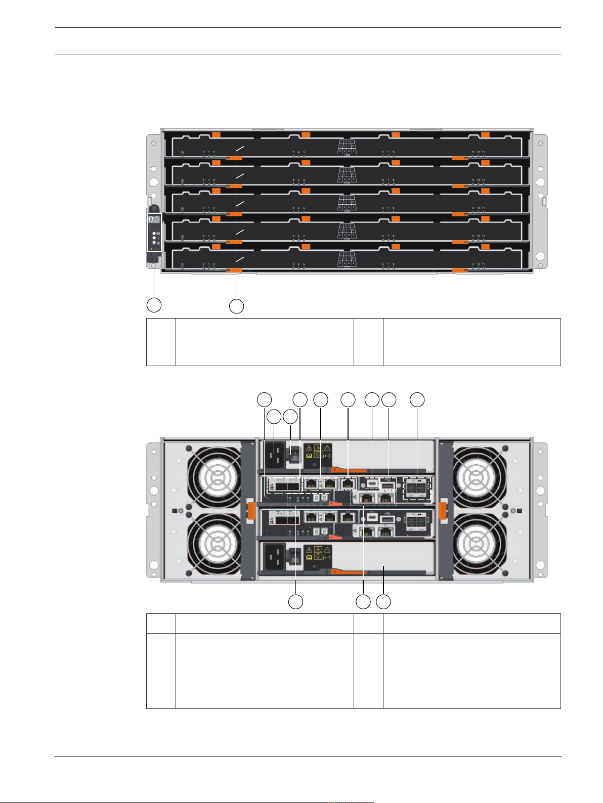
60-bay dual controller unit or expansion unit - front view
1 Status displays 2 Drive drawer1-5 (drive drawer1 is at
the top and drive drawer5 is at the
bottom)
60-bay dual controller unit - rear view
1 ControllerA 2 Mains connection 240 VAC
3 On/off switch 4 Channel3 (left) / Channel4 (right) -
Host interface ports (Dual 10GB
iSCSI, optical)
Note: Use only RJ45 Base‑T ports or
optical ports.
Bosch Security Systems B.V.
Installation manual
2020.11 | V2 | DOC
12 en | System overview DSA E-Series (E2800 60-bay)
5
6 7
11
4
9 108 12 13 14
2
3
1
5 Management port1 (left) /
6 Serial port (RJ45)
Management port2 (right) - Dual
1Gigabit Ethernet
Note: Use only Port1 per controller
(default).
7 Serial port (mini USB) 8 USB port (only for factory use)
9 Dual 12Gb SAS drive expansion ports 10 Status display
11 Channel5 (left) / Channel6 (right) -
12 ControllerB (see ControllerA)
Host interface ports (Dual 10GB
iSCSI, RJ45 Base‑T)
Note: Use only RJ45 Base‑T ports or
optical ports.
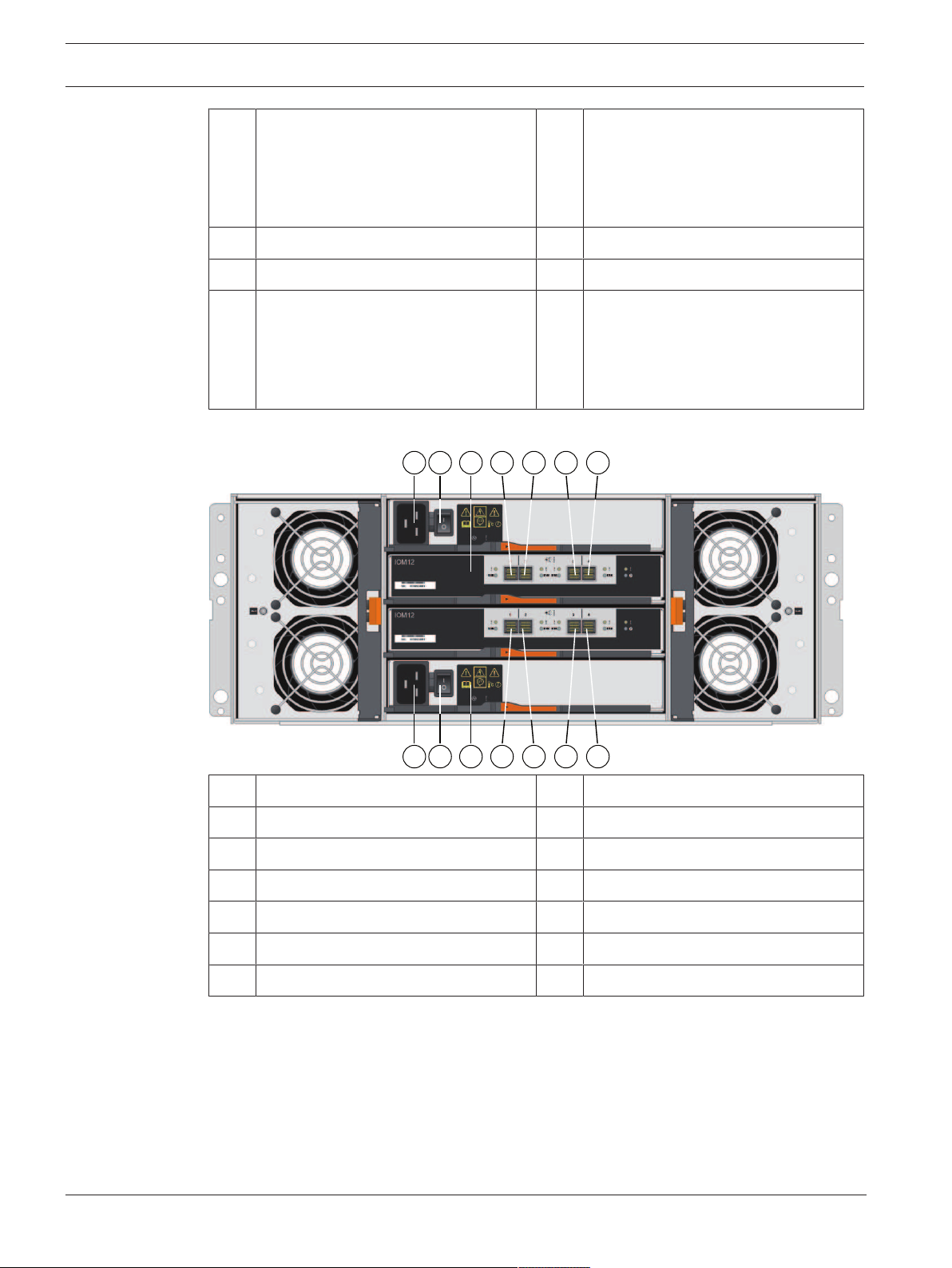
60-bay expansion unit - rear view
1 Mains connection 240VAC 2 On/off switch
3 IOMA 4 IOMA - SAS port1
5 IOMA - SAS port2 6 IOMA - SAS port3
7 IOMA - SAS port4 8 Mains connection 100 - 240 VAC
9 On/off switch 10 IOMB
11 IOMB - SAS port1 12 IOMB - SAS port2
13 IOMB - SAS port3 14 IOMB - SAS port4
3.2 LED description
There are several LEDs on the front and rear of the chassis. The LEDs show the over-all status
of the system and the activity and health of specific components.
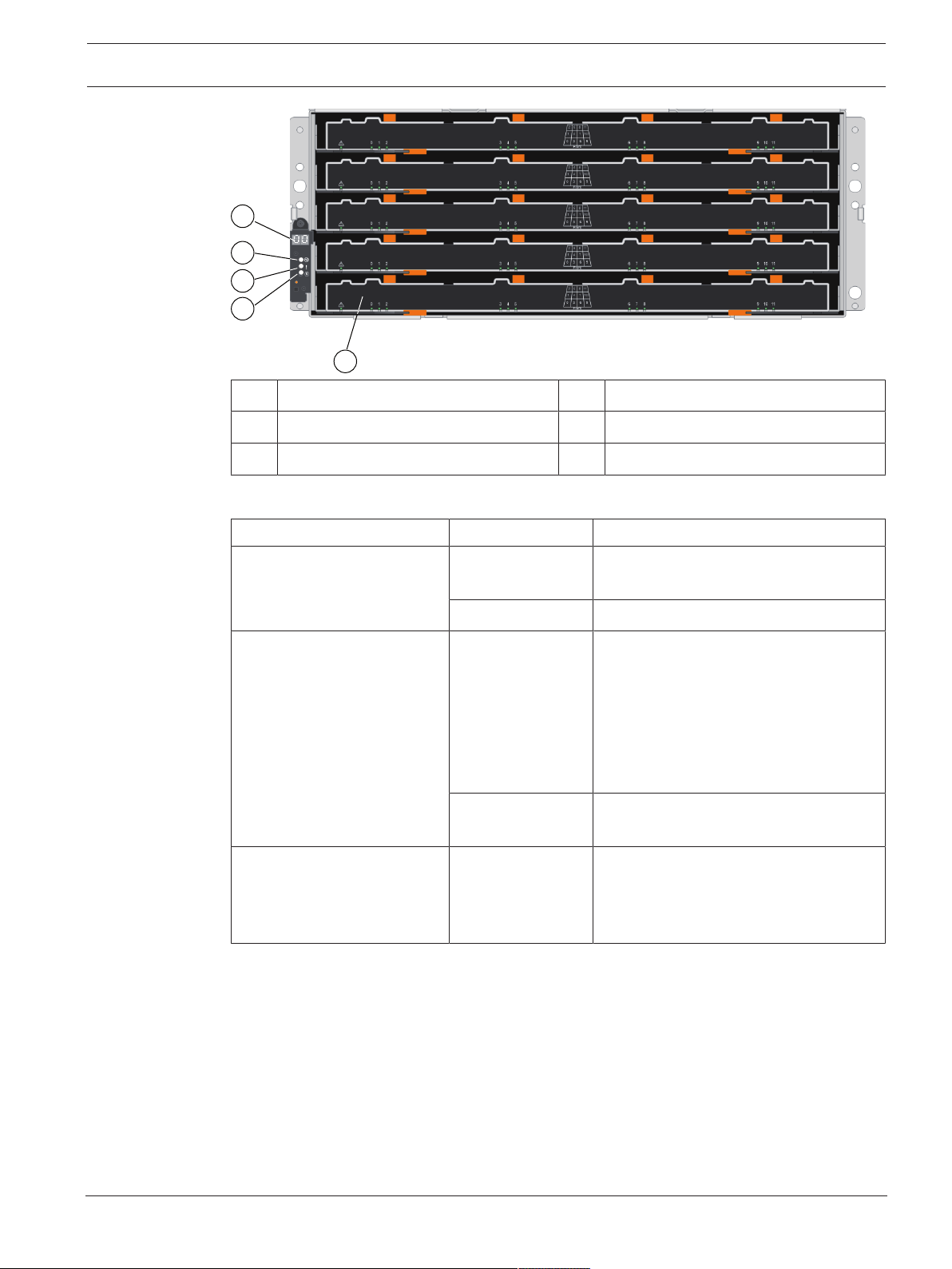
3.2.1 LEDs on the operator display panel
Each controller unit and expansion unit has LEDs located on the operator display panel. The
operator display panel is visible through the front bezel of a controller unit and through the
left end cap of an expansion unit.
2020.11 | V2 | DOC
Installation manual
Bosch Security Systems B.V.
DSA E-Series (E2800 60-bay) System overview | en 13
1
2
3
4
5
1 7-segment display 2 Power LED
3 Attention LED 4 Locate LED
5 Drive canister
The following table describes the LEDs and their operational states:
LED Status indicator Description
Power Green One or more power supplies are
Attention Amber There is an error with the function of
Locate Blue There is an active request to physically
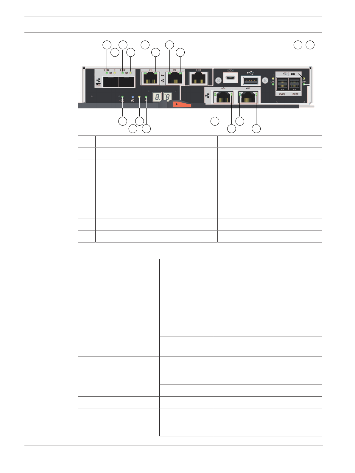
3.2.2 LEDs on the controller unit
The back of the controller unit includes LEDs that indicate the status of the controller. For
example, the controller is active, the controller needs attention, or when there is Ethernet
activity.
supplying power to the unit.
Off The unit is not receiving power.
one or more of the following:
– Unit
– Drives
– IOMs
– Power supplies
– Fans
Off The unit, drives, IOMs, power supply,
and fans are functioning correctly.
locate the shelf.
Note: The Locate LED turns off
automatically after 30minutes.
Bosch Security Systems B.V.
Installation manual
2020.11 | V2 | DOC
14 en | System overview DSA E-Series (E2800 60-bay)
5 9
6
3 7
11
4 8
12
1
2
10
14
13
15
16
17
18
1 Channel3 - host port link status LED 2 Channel3 - host port attention LED
3 Channel4 - host port link status LED 4 Channel4 - host port attention LED
5 Management port1 - Ethernet status
LED
7 Management port2 - Ethernet status
LED
9 SAS drive expansion port - attention
LED
6 Management port1 - Ethernet activity
LED
8 Management port2 - Ethernet activity
LED
10 SAS drive expansion port - link status
LED
11 Cache active LED LED 12 Locate LED
13 Attention LED 14 Activity LED
The following table describes the LEDs and their operational states:
LED Status indicator Description
Cache active Green The cache contains data not yet written
to disk.
Off Either the cache is inactive or all data
from the cache has been preserved in
non-volatile memory.
Locate Blue There is an active request to physically
locate the controller unit.
2020.11 | V2 | DOC
Off There is no active request to locate the
Attention Amber The controller is faulty and requires
Off The controller is operating normally.
Activity Blinking green The controller is active.
Ethernet activity (right) Green The link between the management port
Installation manual
controller unit.
operator attention, and the faulty
component is serviceable.
and the device to which it is connected
(such as an Ethernet switch) is up.
Bosch Security Systems B.V.
DSA E-Series (E2800 60-bay) System overview | en 15
1
2
3
4
LED Status indicator Description
Off There is no link between the controller
and the connected Ethernet port.
Blinking green There is Ethernet activity.
Ethernet link state (left) Green Link is established.
Off No link is established.
SAS expansion port link Green Link is established.
Off No link is established.
SAS expansion port link fault Amber Port is degraded (one or more physical
devices in the port are down).
Off Port is optimal. All physical devices in
the port are up or all physical devices in
the port are down since the LED is off if
no cables are attached.
Host port link status (SFP
host port, FC or iSCSI)
Host port attention (SFP host
port, FC or iSCSI)
Host port link status (RJ-45
host port, iSCSI)
Host port activity (RJ-45 host
port, iSCSI)
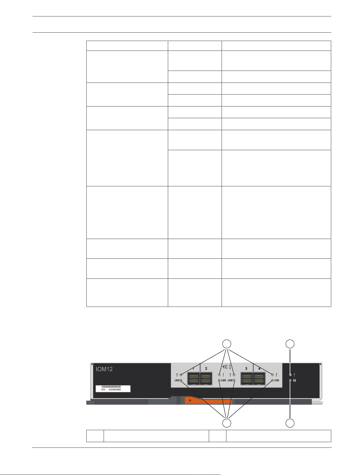
3.2.3 LEDs on the I/O modules
The I/O module (IOM) includes the SAS ports for connecting the expansion units to the
controller units or to other expansion units.
Green The link is up (Fibre channel).
LED is solid: The link is up, but there is
no activity (iSCSI).
LED is flashing: The link is up and there
is activity (iSCSI).
LED is off: The link is down.
Amber The port requires operator attention.
Green LED is on: The link is established.
LED is off: No link is established.
Green LED is on: The link is up with no activity.
LED is blinking: There is link activity.
LED is off: No link is established.
Bosch Security Systems B.V.
1 SAS port attention LED 2 SAS port link LED
Installation manual
2020.11 | V2 | DOC
16 en | System overview DSA E-Series (E2800 60-bay)
1
2
3 IOM attention LED 4 IOM locate LED
The following table describes the LEDs and their operational states:
LED Status indicator Description
Attention Amber The IOM is not functioning correctly.
Off The IOM is functioning correctly.
Locate Blue There is an active request to physically
locate the expansion unit.
Note: When the Locate LED is activated,
the Locate LED on the left end cap of
the expansion unit is also activated.
The Locate LEDs turn off automatically
after 30minutes.
Off There is no active request to locate the
expansion unit.
SAS port link Green The SAS port established a link (with
either a controller or another expansion
unit).
SAS port attention Amber One or more of the links in the port are
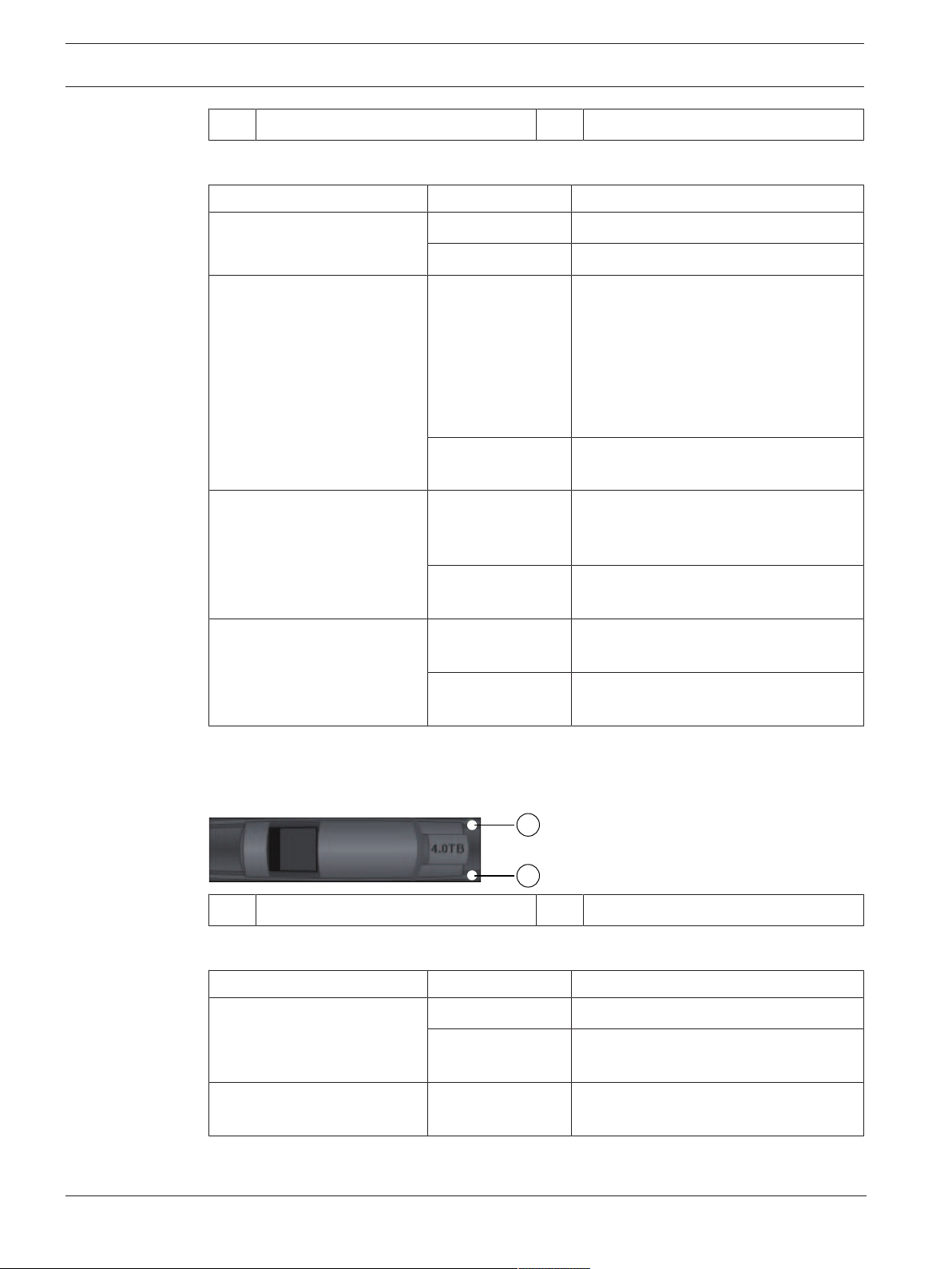
3.2.4 LEDs on the drives
The drives that are installed in the controller unit and the expansion unit include an Activity
LED and an Attention LED.
1 Activity LED 2 Attention LED
The following table describes the LEDs and their operational states:
LED Status indicator Description
Activity Green The drive has power.
Off No link is established to another SAS
port.
not working properly.
Off The port is optimal and no link error has
occurred.
Blinking green The drive has power, and I/O is in
process.
2020.11 | V2 | DOC
Attention Amber An error occurred with the functioning
of the drive.
Installation manual
Bosch Security Systems B.V.
DSA E-Series (E2800 60-bay) System overview | en 17
1
5 9 136 107 11
2 3 4
8 12
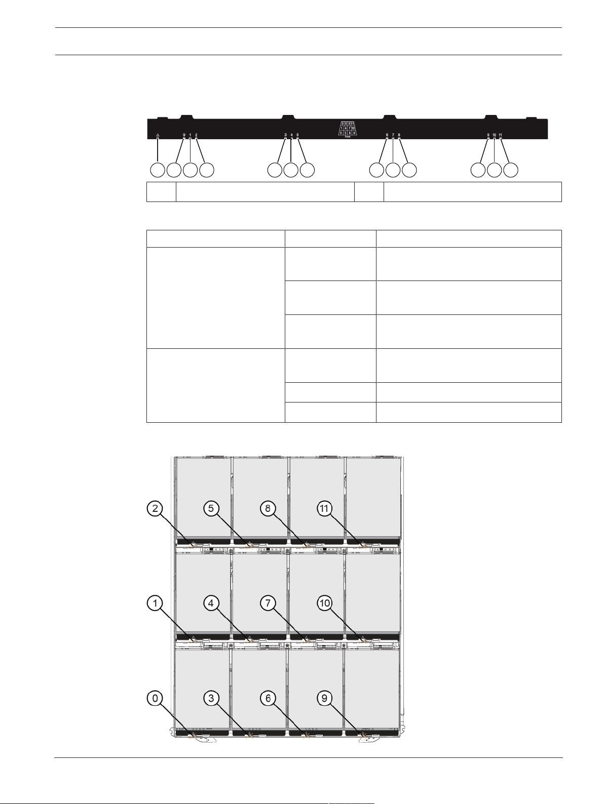
3.2.5 LEDs on the drive drawer
Each of the 5drive drawers in the 60-bay controller unit and the 60-bay expansion unit
includes a single Attention/Locate LED for the unit and 12 Activity LEDs for the drives.
1 Attention/Locate LED 2-13 Activity LEDs
The following table describes the LEDs and their operational states:
LED Status indicator Description
Attention/Locate LED Amber The drawer or a drive in the drawer
requires operator attention.
Off The drawer and all drives in the drawer
are operating normally.
Blinking A locate operation for a drive in the
drawer is in progress.
Activity LEDs
(for drives 0 through 11 in the
drive drawer)
Green The power is turned on and the drive is
operating normally.
Off The power is turned off.
Blinking Drive I/O activity is taking place.
Within a drive drawer, there are 12drive slots numbered 0 through 11. Each drive uses an
amber Attention LED that comes on if the drive requires operator attention
Bosch Security Systems B.V.
Installation manual
2020.11 | V2 | DOC
 Loading...