

Bosch DDC KIT Installation And Operation Manual
Installation and Operation Manual
DDC KIT
8 733 900 571
Revised 05-11

©Copyright 2011 Bosch, Inc All rights reserved

Table of Contents DDC KIT 3
TABLE OF CONTENTS
THE ZONE CONTROLLER ............................................................................. 4
SPECIFICATIONS ........................................................................................ 4
INSTALLATION PROCESS ........................................................................... 5
Mounting Holes ........................................................................................ 5
Install Sensors ......................................................................................... 5
Routing Wire Harness .............................................................................. 6
DDC Wiring Diagrams .................................................................................. 8
For use with TW Models ........................................................................... 8
For use with BP, CP, CE and TA models .................................................... 9
Revised 05-11 Subject to change without prior notice
8 733 900 571
4 DDC KIT The Zone Controller
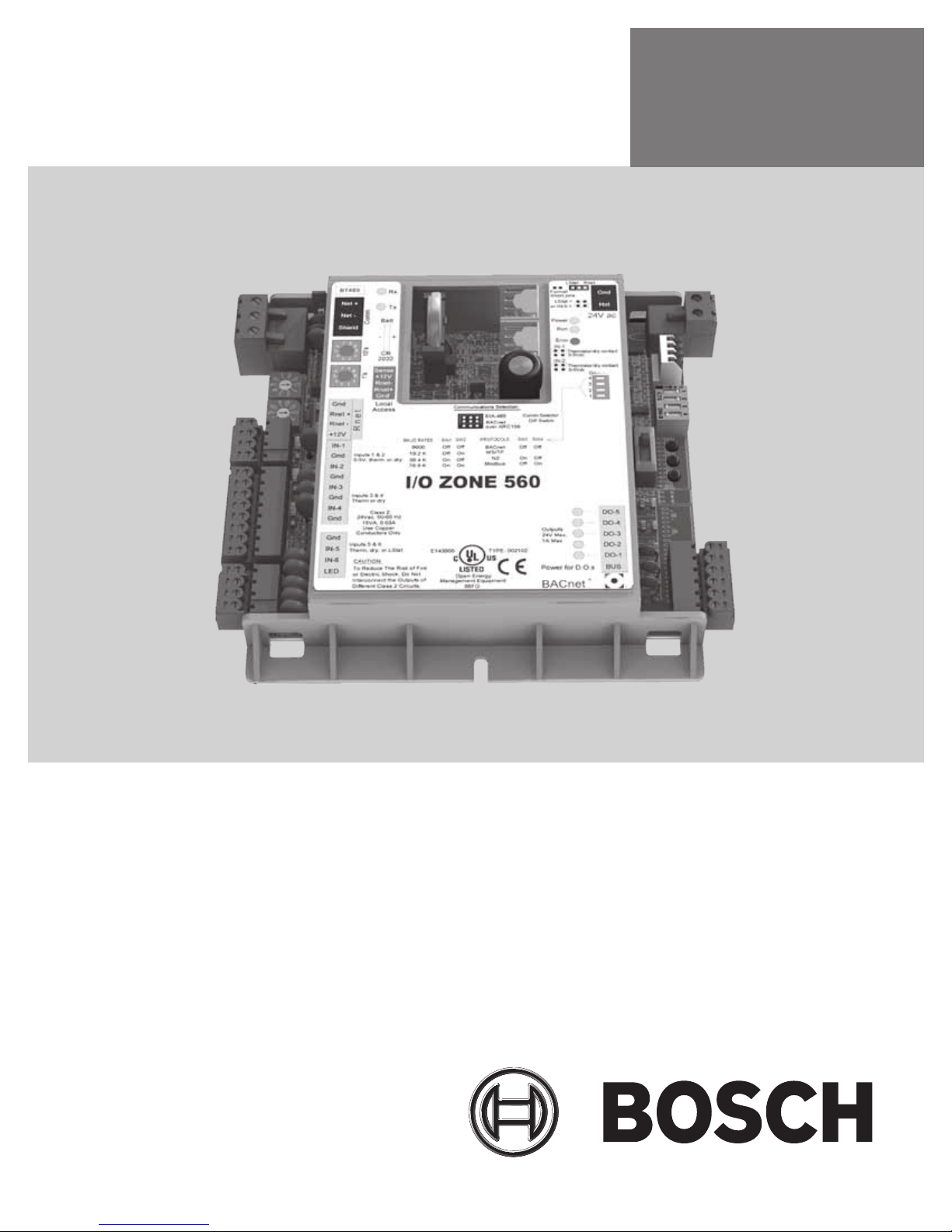
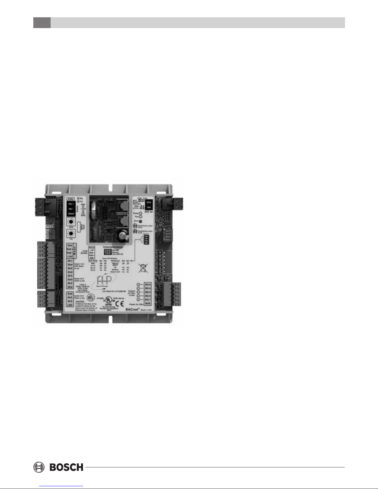
THE ZONE CONTROLLER
The Digital Direct Control board also known as DDC
and shown in Figure #1 is used in most congure to
order applications.
It is BACnet® native which makes it exible and easy
to integrate into existing Building Automation
Systems (BAS). The controller provides the end user
with a superior amount of information when
compared to a traditional thermostat.
The controller is programmed in the factory with
software versions that suit the different application
for the models offered by Bosch. User settings such
as the time and schedules can be preprogrammed or
also change during the installation of the product.
Digital Outputs: Five digital outputs relay contacts
rated at 1A resistive @ 24VAC; congured as dry
contact, normally open.
Universal Inputs: 8 inputs. Inputs 1 and 2 are
congurable for 0-5VDC, 10K ohm thermistor, or
dry contact; inputs 3 and 4 support thermistor or
dry contact only; inputs 5 and 6 support
thermistor, dry contact, or LogiStat.
Standard Communication Ports:
Comm Port: 3-pin port congurable for ARC156
(BACnet-over- ARC156) or EIA485communications (BACnet MS/TP, Modbus
RTU, orN2).
Rnet Port: 4-pin port for interface with remote
mounted BACview6 or RS sensors
Local Access Port: For local communication with a
laptop computer running WebCTRL or for
communication with a BACview6.
Status Indication: Visual (LED) status of network
communication, running, errors, power, and all
digital outputs
Figure #1 - Zone Controller
SPECIFICATIONS
Power: 24VAC ± 10%, 50-60Hz, 20VA power
consumption (Single Class II 70VA or 100VA option
available)
Physical: Rugged plastic housing protects circuitry.
Environmental Operating Range: 40° to 130°F (-17.8°
to 54.4°C); 10 to 90% relative humidity, non-
condensing
Battery: Lithium 3V coin cell battery, CR2032, provides
a minimum of 10,000 hours of Data retention
during power outages
Protection: Surge and transient protection circuitry for
power and communications.
Listed by: FCC Part 15 - Subpart B - Class A. Pending
listings at the time of publishing this document: UL
916 (PAZX), cUL C22.2 No. 205-M1983 (PAZX7),
CE (1997).
Weight: 0.6 lbs. (0.27 Kg).
Overall Dimensions: 5-1/16” (width) by 5-11/16”
(height) by 1-1/2” (recommended panel depth).
129mm (width) by 144mm (height) by 38mm
(recommended panel depth).
Mounting Hole Dimensions: Two mounting holes
center line as at left with 5-9/16” (141mm)
Spacing (height)
8 733 900 571
Subject to change without prior notice Revised 05-11
 Loading...