

Page 1
DICENTIS
Wireless Conference System
Page 2

en Installation Manual
Page 3

DICENTIS Table of Contents | en 3
Table of contents
1
1.1 Battery Pack 4
1.2 Charger 4
1.3 Wireless Access Point 4
1.4 Frequency bands and power output specifications for European RED directive
1.5 Statements for FCC & Industry Canada 5
1.6 Statement for Brazil 6
1.7 Statement for Mexico 6
1.8 Local authority wireless approval 6
2
2.1 Intended audience 7
2.2 Alerts and notice signs 7
2.3 Copyright and disclaimer 7
2.4 Document history 8
3
3.1 Extended system requirements 12
4
4.1 Unpacking 13
4.2 System design planning 13
4.3 Installation planning 13
4.4 Additional components 15
5
6
6.1 Microphones 24
6.2 Battery Pack 25
6.3 Charger 28
7
8
8.1 Cleaning 34
8.2 Inspect components 34
8.3 Service 34
9
9.1 Wireless Access Point (DCNM-WAP) 35
9.2 Wireless Devices (DCNM-WD and DCNM-WDE) 37
9.3 Battery Pack (DCNM-WLIION) 40
9.4 Charger (DCNM-WCH05) 41
9.5 High Directive Microphone (DCNM-HDMIC) 42
9.6 Microphones (DCNM-MICx) 43
10
10.1 Product labels for South Korea and the Philippines 44
Safety 4
(2014/53/EU)
About this manual 7
System overview 9
Planning 13
Installation Wireless Access Point 16
Installation Wireless Devices and Accessories 22
System power on and configuration 33
Maintenance 34
Technical data 35
Appendices 44
5
Bosch Security Systems B.V. Installation Manual 2017.09 | V2.1 |
Page 4
!
4 en | Safety DICENTIS
1
1.1
Safety
Prior to installing or operating products, always read the Important Safety Instructions which
are available as a separate multilingual document: Important Safety Instructions (Safety_ML).
These instructions are supplied together with all equipment that can be connected to the
mains supply.
Old electrical and electronic appliances
Electrical or electronic devices that are no longer serviceable must be collected separately and
sent for environmentally compatible recycling (in accordance with the European Waste
Electrical and Electronic Equipment Directive).
To dispose of old electrical or electronic devices, you should use the return and collection
systems put in place in the country concerned.
Battery Pack
Please take notice of the safety instructions printed on the label of the Battery Pack
(DCNM‑WLIION).
Warning!
DCNM-WLIION transportation
– Due to changed regulations the DCNM‑WLIION can only be shipped by air when it is
charged with a maximum of 30 %. When shipment by air is required, please make sure
that only 1 LED on the battery is green.
– The battery can be discharged to show 1 active led (<30%) by using the DCNM‑WLIION in
a Wireless device, in an active system.
1.2
1.3
Charger
The Charger (DCNM‑WCH05) must be fixed installed to the wall by qualified service personnel,
using the supplied mounting bracket. Disassembly is also only allowed by qualified service
personnel.
Wireless Access Point
If you want to attach the Wireless Access Point (DCNM‑WAP) to a wall, it must be correctly
installed as described in this manual. Refer to Installation Wireless Access Point, page 16.
2017.09 | V2.1 | Installation Manual Bosch Security Systems B.V.
Page 5
DICENTIS Safety | en 5
1.4
1.5
Frequency bands and power output specifications for European RED directive (2014/53/EU)
System info
Frequency band Power output
2400 - 2483.5 MHz < 20 dBm
5150 - 5350 MHz < 23 dBm
5470 - 5725 MHz < 30 dBm
DCNM-WDE
NFC Frequency band
13.56 MHz < 25 dBuA/m
Power limit
Statements for FCC & Industry Canada
This Class A digital apparatus complies with Canadian ICES-003. Cet appareil numérique de la
classe A est conforme à la norme NMB‑003 du Canada.
This equipment has been tested and found to comply with the limits for a Class A digital
device, pursuant to Part 15 of the FCC Rules. These limits are designed to provide reasonable
protection against harmful interference when the equipment is operated in a commercial
environment. This equipment generates, uses, and can radiate radio frequency energy and, if
not installed and used in accordance with the instruction manual, may cause harmful
interference to radio communications. Operation of this equipment in a residential area is
likely to cause harmful interference in which case the user will be required to correct the
interference at their own expense.
The Wireless Devices and the Wireless Access Point comply with Part 15 of the FCC Rules and
with RSS-210/RSS-247 of Industry Canada. Operation is subject to the following two
conditions:
1. This device may not cause harmful interference.
2. This device must accept any interference received, including interference that may cause
undesired operation.
Notice!
Changes or modifications made to this equipment, not expressly approved by Bosch Security
Systems B.V. may void the FCC authorization to operate this equipment.
Notice!
The Wireless Devices and the Wireless Access Point comply with FCC radiation exposure
limits set forth for an uncontrolled environment. The Wireless Devices and the Wireless
Access Point should be installed and operated with minimum distance of 20 cm to your body.
Bosch Security Systems B.V. Installation Manual 2017.09 | V2.1 |
Page 6

6 en | Safety DICENTIS
1.6
1.7
1.8
Statement for Brazil
"Este equipamento opera em caráter secundário, isto é, não tem direito a proteção contra
interferência prejudicial, mesmo de estações do mesmo tipo, e não pode causar interferência
a sistemas operando em caráter primário."
Statement for Mexico
“La operación de este equipo está sujeta a las siguientes dos condiciones:
(1) es posible que este equipo o dispositivo no cause interferencia perjudicial y
(2) este equipo o dispositivo debe aceptar cualquier interferencia, incluyendo la que pueda
causar su operación no deseada.”
Local authority wireless approval
Although the DICENTIS Wireless Conference System operates in a license-free band, it is
subject to local certification regulations. Please contact your nearest Bosch representative for
more information on the regulations for your country.
2017.09 | V2.1 | Installation Manual Bosch Security Systems B.V.
Page 7

!
!
DICENTIS About this manual | en 7
2
2.1
2.2
About this manual
The purpose of this manual is to provide information required for installing the DICENTIS
Wireless Conference System.
– Please read this manual carefully before installing any of the products of the DICENTIS
Wireless Conference System.
– Retain all documentation supplied with the products for future reference.
– This installation manual is available as a digital document in the Adobe Portable
Document Format (PDF).
– For more information, refer to the product related information on:
www.boschsecurity.com > Country of your choice > Conference Systems > DICENTIS
Wireless Conference System
Intended audience
This hardware installation manual is intended for installers of a DICENTIS Wireless Conference
System.
Alerts and notice signs
Four types of signs can be used in this manual. The type is closely related to the effect that
may be caused if it is not observed. These signs - from least severe effect to most severe
effect - are:
Notice!
Containing additional information. Usually, not observing a ‘notice’ does not result in damage
to the equipment or personal injuries.
2.3
Caution!
The equipment or the property can be damaged, or persons can be lightly injured if the alert
is not observed.
Warning!
The equipment or the property can be seriously damaged, or persons can be severely injured
if the alert is not observed.
Danger!
Not observing the alert can lead to severe injuries or death.
Copyright and disclaimer
All rights reserved. No part of this document may be reproduced or transmitted in any form by
any means, electronic, mechanical, photocopying, recording, or otherwise, without the prior
written permission of the publisher. For information on getting permission for reprints and
excerpts, contact Bosch Security Systems B.V..
The content and illustrations are subject to change without prior notice.
Bosch Security Systems B.V. Installation Manual 2017.09 | V2.1 |
Page 8

8 en | About this manual DICENTIS
2.4
Document history
Release date Documentation version Reason
2015.02 V1.0 1st edition.
2015.03 V1.01 Section 6 adapted.
Minor text changes in the
whole document.
2016.07 V2.0 New sections: 1.2, 1.3, 1.5,
1.6, 4.2, 4.3, 10, 10.1.
Sections shifted: 1.2 > 1.4,
4.2 > 4.4.
Sections updated: 2.4, 3, 3.1,
4.4, 5, 6, 6.1, 6.2, 6.3, 9.2,
9.3.
2017.08 V2.1 New section: 1.4
Sections updated: 1.1, 1.7.
2017.09 | V2.1 | Installation Manual Bosch Security Systems B.V.
Page 9
8
9
6
7
1
4
5
9
2
3
DICENTIS System overview | en 9
3
System overview
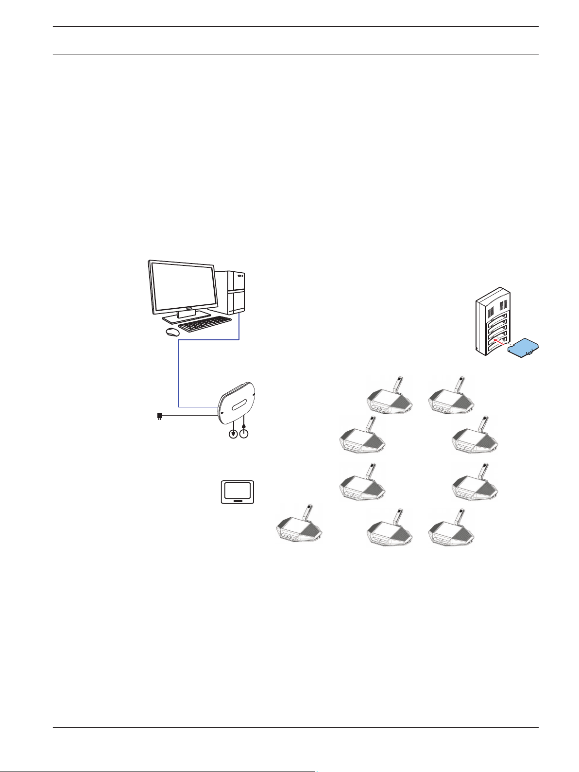
The DICENTIS Wireless Conference System is a “standalone” IP based system. It uses
WiFi IEEE 802.11n for wireless distribution and processing of audio and data signals.
Typical DICENTIS Wireless Conference System
A typical DICENTIS Wireless Conference System (see following figure and numbering on next
page) consists of:
– a Wireless Access Point (1), including the power supply adapter (2),
– Wireless Devices (4 + 5), including Battery Pack and microphone,
– a tablet device (7) for operational use, or
– a PC/laptop (8) for operational use, and licensing/updating the system software (if the
PC is not required for operational use, it can be disconnected from the system after
licensing/updating the system software).
– a Battery Pack Charger (6).
Figure 3.1: Typical DICENTIS Wireless Conference System
Bosch Security Systems B.V. Installation Manual 2017.09 | V2.1 |
Page 10
14
11
7
9
12
11
12
9
12
HD-SDI
13
6
9
7
1
2
3
4
5
10
9
8
9
en | System overview DICENTIS
10
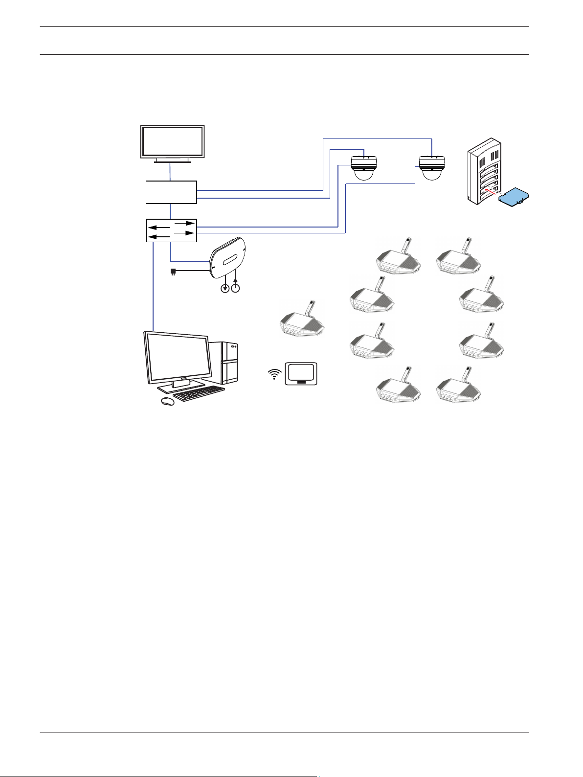
Typical extended DICENTIS Wireless Conference System
A typical extended DICENTIS Wireless Conference System (see the following figure and
numbering on the next page) has an additional Ethernet network switch/video switch (10) and
HD Conference Dome (11).
Figure 3.2: Typical extended DICENTIS Wireless Conference System
1. The Wireless Access Point (DCNM‑WAP) is the central component of the DICENTIS
Wireless Conference System. It is used for:
– hosting a web browser interface for licensing, configuring and controlling the
system.
– controlling the system audio, and routing the audio from and to the Wireless Devices.
– environment wireless channel scanning. The best available wireless channel will be
chosen for the system.
– Camera control. It controls the optional connected switch (10) and cameras (11).
Note: If more than one camera is connected to the system, a video switch (13) is
required.
2. AC/DC power supply adapter (supplied with the DCNM‑WAP).
3. (Optional connections) Audio line input and audio line output.
4. Wireless Device (DCNM‑WD): used as a single-use, dual-use or chairperson Wireless
Device, including Battery Pack and microphone (both to be ordered separately).
– Participants can use the Wireless Device to participate in a discussion.
5. Wireless Device Extended (DCNM‑WDE): used as a single-use, dual-use or chairperson
Wireless Device, extended with Near Field Communication (NFC) reader for user
identification and 4.3” capacitive touch screen, including Battery Pack and microphone
(both to be ordered separately).
– Participants can use the Wireless Device Extended to participate in a discussion.
6. Charger (DCNM‑WCH05): used to charge the Battery Packs of the Wireless Devices.
2017.09 | V2.1 | Installation Manual Bosch Security Systems B.V.
Page 11

DICENTIS
System overview | en 11
7. Tablet device:
– Used to configure and control the system via the website hosted on the DCNM‑WAP.
8. PC/Laptop:
– Used to configure and control the system if a tablet is not used.
– Used to license and update the systems firmware, as required.
9. Ethernet cable/PoE+:
– Used for connection to the Ethernet.
– PoE+ is used for powering the DCNM‑WAP.
10. Ethernet network switch:
– Routes the system data via Ethernet.
11. Optional HD Conference Dome:
– Captures the video of a speaking participant.
12. Coax cable: transports the signal between the camera and the video switch (13).
13. Video switch:
– TV-One CORIOmatrix mini and the Kramer MV-6 are supported.
– Connected between the display (14) with the Ethernet network switch (10).
14. Display: Shows the speaking participant.
DICENTIS Wireless Conference System system with redundant WAP
The system can be configured with a redundant DCNM‑WAP provided the following conditions
are met. The procedure for subscribing a redundant DCNM‑WAP is described in the
Configuration manual.
– Preferably both WAPs are connected to an Ethernet network switch with a DCN
multimedia System Network Cable or a standard network cable, and the Ethernet
network switch is connected to a laptop or PC.
Note: The use of an Ethernet network switch and cabling are preferred during the
subscription process, because this makes it easier to access and subscribe the WAPs.
When subscription of the secondary WAP is complete, the Ethernet network switch and
cabling can be removed if it is no longer required.
– The WAPs are correctly positioned (there should be a minimum distance of one meter
and a maximum distance of three meters between the two WAPs).
– The WAPs are powered up and the Wireless Conference System is operational.
– Both WAPs have been correctly configured in the Installation Wizard and have unique
names for:
– Network name (SSID)
– WPA2 key
– Hostname
– Both WAPs are set to the Standalone (factory default).
– The applicable licenses are available for the primary WAP and the secondary WAP (the
redundant WAP requires its own set of licenses for features such as voting and dual-use
at seat to continue working if the primary WAP fails).
– If recording/playback and PA are required, make sure audio connectors are connected to
the balanced In/Out connectors of both the primary and secondary WAP.
– If access to the API (for showing voting results) and web browser settings is required,
make sure Ethernet cables are connected to both the primary and secondary WAP.
Bosch Security Systems B.V. Installation Manual 2017.09 | V2.1 |
Page 12

12 en | System overview DICENTIS
3.1
Extended system requirements
The following requirements are valid if you want to extend your system with a network switch
or cameras:
– Network switch and camera installation instructions are not part of this installation
manual; please consult the product related documentation of the supplier.
– A video switch is required, when more than one camera is required. The following
switches are supported:
– tvONE CORIOmaster mini C3-510
– Kramer MV-6 3G HD-SDI Multiviewer
– A DHCP server is needed for both the Wireless Access Point and the cameras.
Cameras
Typical, the Bosch HD Conference Dome is used. Refer to product related information on:
www.boschsecurity.com > Country of your choice > Conference Systems > DICENTIS Wireless
Conference System > HD cameras and accessories.
2017.09 | V2.1 | Installation Manual Bosch Security Systems B.V.
Page 13

DICENTIS Planning | en 13
4
4.1
4.2
Planning
Use the guidelines in this section to plan the design and installation of your DICENTIS Wireless
Conference System.
Unpacking
This equipment should be unpacked and handled with care. If an item appears to be damaged,
notify the shipper immediately. If any items are missing, notify your Bosch representative.
The original packaging is the safest container in which to transport products and can be used
to return products for service if necessary.
System design planning
– If the DICENTIS Wireless Conference System is used in an area where there are other
WiFi access points within (30 m) range of the DCNM‑WAP, you should apply frequency
planning. Put the other access points on manual frequency selection to prevent the WiFi
networks from trying to use the same frequency.
– Probing of other WiFi devices (such as smart phones or tablets) to the DICENTIS Wireless
Conference System can cause unstable functionality. Therefore it is strongly
recommended that these WiFi devices are connected to dedicated WiFi access points.
These WiFi access points must have sufficient capacity for WiFi connection of all nearby
WiFi devices.
– The maximum distance between the DCNM‑WAP and the Wireless Devices can be
reduced by RF absorbance of signal radiation of certain building materials e.g. concrete,
and or metal.
– When using a smart device with a wireless connection to the system, the maximum
number of connected Wireless Devices must be reduced. With 1 smart device, 119
Wireless Devices can be controlled, and up to 3 smart devices can be used to control 117
Wireless Devices. Otherwise use a wired connection to the DCNM‑WAP to maintain the
maximum number of 120 Wireless Devices.
4.3
Bosch Security Systems B.V. Installation Manual 2017.09 | V2.1 |
Installation planning
1. Make sure you have all components for installing and connecting the DICENTIS Wireless
Conference System (see System overview, page 9).
– Familiarize yourself with the products capabilities of the DICENTIS Wireless
Conference System (see System overview, page 9 and the paragraphs Control capacity
and Coverage area in this section).
– Use only Bosch specified installation materials and tools (see Additional components,
page 15).
2. Determine the end‑user requirements, typical questions are:
– The number of seats?
– How many chairpersons are required?
– Should the Wireless Devices be in dual‑use mode?
– Is voting required?
– Is identification required?
– Is camera control required?
3. Calculate the number of seat positions. This depends on, the number of participants, the
number of chairpersons and whether the Wireless Devices will be in single‑use or
dual‑use.
Page 14

14 en | Planning DICENTIS
– Example: The system requires 25 participants and one chairperson. Two participants
will use one Wireless Devices. Use the following formula to calculate how many
devices are required: Round up (participants/2) + chairperson.
In this example 25/2 = 12.5 > Round up (12.5) = 13 + 1 = 14 Wireless Devices.
4. If camera control is a required, the license DCNM-LCC must be added to the system. Do
not forget to add the cameras to the system. The Bosch HD Conference Dome is
supported.
5. Decide if, and which type of, cabling is required. See System overview, page 9.
6. Decide on how to power the Wireless Access Point (DCNM‑WAP). See System overview,
page 9:
– Via the AC/DC power supply adapter (supplied with the DCNM‑WAP). Or:
– Via Power over Ethernet (PoE). Or:
– Via Ethernet switch. Or:
– DICENTIS (Audio) Powering Switch.
7. Provide a mains power supply connections nearby the equipment which requires mains
power supply.
8. Decide on how to power the other devices used in the system (i.e. Ethernet switch,
cameras etc.). See System overview, page 9:
– Via their own (mains) power supply provision. Or:
– Via Power over Ethernet (PoE), if possible.
9. Decide on how, and where, to install the Wireless Access Point (DCNM‑WAP). See
Installation Wireless Access Point, page 16:
– Wall, ceiling. Or:
– Tripod floor stand.
10. Decide where, and how to place, the Wireless Devices (DCNM‑WD and/or DCNM‑WDE).
See Installation Wireless Devices and Accessories, page 22.
11. Decide on how, and where to attach the Charger to a wall. See Charger, page 28.
Control capacity
– The Wireless Access Point (DCNM‑WAP) can control a maximum of 120 wireless
connections. A wireless connection can be:
– a Wireless Device (DCNM‑WD or DCNM‑WDE), or
– a Wireless Device with web browsing functionality, such as a tablet or laptop.
– A maximum of one DCNM‑WAP can be used to control the system.
Coverage area
– All Wireless Devices need to be in the WiFi coverage area of the DCNM‑WAP.
– For a maximum WiFi coverage area, the DCNM‑WAP can be placed on a central
location in the room.
– The DCNM‑WAP has a typical WiFi coverage area of 30 m by 30 m.
802.11n specification
The DICENTIS Wireless Conference System network is based on the 802.11n specification for
WiFi technology. Devices that comply to the 802.11n specification operate in frequency bands
between 2.4000 and 2.4835 GHz and 5.180 and 5.700 GHz.
Notice!
Although the system operates on frequencies which are license free world wide, you must be
aware of country specific limitations and follow them.
2017.09 | V2.1 | Installation Manual Bosch Security Systems B.V.
Page 15

DICENTIS Planning | en 15
4.4
Additional components
The following additional components can be used with the DICENTIS Wireless Conference
System, as required:
6.3 mm jack cables – These cables are required if you want to connect optional audio
equipment to the audio line input and/or audio line output of the Wireless Access Point
(DCNM‑WAP), such as microphones and a sound reinforcement system.
CAT5e cables - These cables are required if you want to connect a PC/Laptop to the Wireless
Access Point (DCNM‑WAP) for running the web browser interface and connecting a switch and
HD Conference Domes.
Bosch Security Systems B.V. Installation Manual 2017.09 | V2.1 |
Page 16

02
01
TORX 10
16 en | Installation Wireless Access Point DICENTIS
5
Installation Wireless Access Point
Use the following steps to install the Wireless Access Point (DCNM‑WAP).
1. Make sure all equipment is available as described in Delivered with product.
2. Optional set the “Brand logo” in the correct orientation.
3. Connect the cabling and install the Wireless Access Point to the wall/ceiling or tripod
floor stand.
4. Power on the Wireless Access Point.
Delivered with product
The Wireless Access Point (DCNM‑WAP) is shipped with the following parts:
Quantity Component
1 DCNM‑WAP Wireless Access Point
1 AC/DC power supply adapter. Including: AC plug‑AU, AC plug‑UK,
AC plug‑EU, AC plug‑US, GE24I48‑R7B
1 Mounting bracket
1 DVD with manuals and software
1 Safety instructions
Brand logo
The orientation of the logo could be changed.
Figure 5.1: Change logo orientation
2017.09 | V2.1 | Installation Manual Bosch Security Systems B.V.
Page 17

!
1
2 3 4 5 6
DICENTIS Installation Wireless Access Point | en 17
Cabling and wall/ceiling/tripod floor stand installation
The Wireless Access Point is provided to be installed to a wall, a ceiling or on a tripod floor
stand. Take care of the installation location regarding the wireless signal coverage area
between the Wireless Access Point and the Wireless Devices. See Planning, page 13.
Caution!
Do not open the Wireless Access Point. Any hardware change makes the product certificates
invalid. Only qualified personnel may open the Wireless Access Point.
Cable connections:
Figure 5.2: DCNM‑WAP front and bottom view
1. Connect an external balanced audio line input (4), if required.
2. Connect the balanced audio line output (6) to an external audio system, if required.
3. Connect the Ethernet (PoE) (2) or AC/DC power supply adapter (3).
For detailed connection description, see the “Power on / connection and indicator” paragraph
at the end of this section.
Bosch Security Systems B.V. Installation Manual 2017.09 | V2.1 |
Page 18

02
01
TORX 10
en | Installation Wireless Access Point DICENTIS
18
Wall or ceiling installation
Use the mounting bracket to attach the Wireless Access Point to a wall or ceiling.
Figure 5.3: Mounting to a wall or ceiling
2017.09 | V2.1 | Installation Manual Bosch Security Systems B.V.
Page 19

02
01
DICENTIS
Installation Wireless Access Point | en 19
Tripod floor stand installation
Use the mounting bracket to install the Wireless Access Point on a Bosch LBC1259/01
universal tripod floor stand.
Figure 5.4: Mounting on a tripod floor stand
Bosch Security Systems B.V. Installation Manual 2017.09 | V2.1 |
Page 20

1
2 3 4 5 6
20 en | Installation Wireless Access Point DICENTIS
4) Power on / connections and indicators
The DCNM‑WAP is powered via one of the three power supply sources marked with an * in the
table below. As soon the power supply is provided, the Wireless Access Point is powered on,
and the six LEDs (1) on the front side are all on.
– To configure the DCNM‑WAP, refer to the configuration manual of the DICENTIS Wireless
Conference System.
Figure 5.5: DCNM‑WAP front and bottom view
Item
Description
1 2x 3 status LED: Gives detailed information about the condition of the Wireless
Access Point and the wireless network. Refer to the software configuration
manual of the DICENTIS Wireless Conference System.
2 Network / DCN multimedia / PoE socket. Powered with:
– * DCN multimedia System Network Cable (48VDC) from DCNM‑(A)PS, or:
– * Standard Power over Ethernet cable (POE 802.3at Type1)”.
– Also standard Ethernet cable can be used (e.g. for camera or wired
connection with PC/Laptop).
Connects the Wireless Access Point point to the wired Ethernet network. For
DCN multimedia System Network Cable, see Additional components, page 15.
3 – * AC/DC power supply 48VDC socket (Power supply adapter supplied with
the DCNM‑WAP).
2017.09 | V2.1 | Installation Manual Bosch Security Systems B.V.
Page 21

DICENTIS
Installation Wireless Access Point | en 21
Item Description
4 Balanced audio line output socket: Connection to a public address system,
audio mixers or to a voice logging system for audio registration of all spoken
conference proceedings. Use standard line output cabling. 6.3mm (1/4") jacks
with the following pinning:
Tip: Live (+)
Ring: Return (-)
Sleeve: Shield
6 Balanced audio line input socket: Connection from audio source. Use standard
line output cabling. 6.3 mm (1/4") jacks with the following pinning:
Tip: Live (+)
Ring: Return (-)
Sleeve: Shield
5 Reset‑to‑default button: Sets the DCNM‑WAP to factory default values. Press
and hold for at least 8 seconds to set all settings to factory default.
See also
– Planning, page 13
– Additional components, page 15
Bosch Security Systems B.V. Installation Manual 2017.09 | V2.1 |
Page 22

!
1 2 3
11
4
16 1817
5 6 7 8 9 10
9
10
12 13
14
15
!
22 en | Installation Wireless Devices and Accessories DICENTIS
6
Installation Wireless Devices and Accessories
The Wireless Devices are used to add participants to a discussion. See System overview, page
9, if required.
Delivered with product
– The DCNM‑WD and DCNM‑WDE are shipped without (accessory) parts.
Installation
The Wireless Devices are free‑standing (table-top use). No mechanical installation, other than
the accessories as described below, is required.
Caution!
If a Wireless Device Extended is moved from a warm and humid environment to a cold
environment there is a possibility that some condensation can form on the display. To prevent
this from happening, make sure each Wireless Device Extended is given sufficient time to
acclimatize.
DCNM‑WDE and DCNM‑WD top, rear and base view
Caution!
2017.09 | V2.1 | Installation Manual Bosch Security Systems B.V.
Do not open the Wireless Device. Any hardware change makes the product certificates
invalid. Only qualified personnel may open the Wireless Devices.
Installation of accessories
Follow below steps to install the required accessories to, and placing of, the Wireless Devices.
These steps are a summary:
1. Check that all equipment is available.
2. For your reference, see the Wireless Device figure and table in this section.
Page 23

DICENTIS Installation Wireless Devices and Accessories | en 23
3. Install the Battery Pack (15) in each Wireless Device to be used. Refer to Battery Pack ,
page 25.
4. Attach the microphones to the Wireless Devices (11). Refer to Microphones, page 24.
5. Place the Wireless Devices in the coverage area of the Wireless Access Point
(DCNM‑WAP). See Planning, page 13, if required.
Connection, indicators and controls
The following table gives an overview of the Wireless Device items and functionality (Refer to
the numbers in the previous figure).
Connection and configuration of the Wireless Devices within the system is done via
DCNM‑WAP. Refer to the software configuration manual of the DICENTIS Wireless Conference
System.
Item
Description
1 Near Field Communication (NFC) user identification (DCNM‑WDE only). Used to
identify the (logon) participant with an NFC Tag.
2 4.3” capacitive touch screen (DCNM‑WDE only).
3 Loudspeaker.
4 + 5 Combined button, depending on software configuration:
– chairperson priority button (4). Or,
– single-use device mute button (4). Or,
– dual-use device microphone request button (5).
6 LED (lightguide) microphone request button (5).
7 Microphone request button (single-use, chairperson or dual-use mode).
8 LED (lightguide) microphone request button (7).
9 Headphone volume control.
10 3.5 mm stereo jack for headphone.
11 Microphone (input) connector.
12 Red battery‑low LED indicator. The LED is flashing when the Battery Pack of the
Wireless Device is empty within 1 hour. Charging the Battery Pack is advised.
See Battery Pack , page 25.and Charger, page 28.
13 Yellow out‑of‑range LED indicator. The LED is on when the Wireless Device is not
(yet) connected with the Wireless Access Point (DCNM‑WAP). Move the Wireless
Device within the coverage area of the DCNM‑WAP . The LED is flashing when
the Wireless Device is trying to make a connection with the Wireless Access
Point (DCNM‑WAP. See Planning, page 13.
14 (DCNM‑WLIION) Battery Pack locking clip. See Battery Pack , page 25.
15 (DCNM‑WLIION) Battery Pack. See Battery Pack , page 25.
16 De‑init button. When push (>2 seconds), the subscription between the Wireless
Device and Wireless Access Point is removed.
17 (DCNM‑WLIION) Battery Pack capacity test button. See Battery Pack , page 25.
18 (DCNM‑WLIION) Battery Pack capacity LED (5x) indicators. See Battery Pack ,
page 25.
Bosch Security Systems B.V. Installation Manual 2017.09 | V2.1 |
Page 24

9
3
6
4
7
1
2
5
8
2
6
4
7
1
2
5
8
24 en | Installation Wireless Devices and Accessories DICENTIS
See also
– Battery Pack , page 25
– Microphones, page 24
– Planning, page 13
– Charger, page 28
6.1
Microphones
Figure 6.1: DCNM‑HDMIC or DCNM‑MICx to Wireless Device connection
Both the DCNM‑HDMIC High Directive Microphone and DCNM-MICL/S Stem Microphone are
typically used with the DICENTIS devices.
Figure 6.2: DCNM‑HDMIC and DCNM‑MICS / DCNM‑MICL front and bottom view
2017.09 | V2.1 | Installation Manual Bosch Security Systems B.V.
Page 25

9
6
4
857
DICENTIS Installation Wireless Devices and Accessories | en 25
Number Description
1 LED indicator.
2 Microphone grill.
3 Adjustable stem (DCNM‑MICS / DCNM‑MICL).
4 Connection guidance.
5 Slider guidance.
6 Connector plug.
7 Lock-slider for lock release (Press and shift to release).
8 Lock.
9 Device female connector (see following figure).
How to connect or remove the microphone
The microphone can be easily connected to the DICENTIS devices:
6.2
Figure 6.3: DCNM‑HDMIC or DCNM-MICS / DCNM-MICL connection
To do so:
1. Gently guide the connection guidance (4) into the DICENTIS device microphone
connector (9).
2. Gently push the connector plug (6) into the device microphone connector (9) until the
connection lock (5) fits/click into place.
3. To remove the microphone from the device: Shift lockslider (7) towards the device and
hold in place lock release (8) and pull out the microphone.
Battery Pack
The Battery Pack (DCNM‑WLIION) provides the power supply of the Wireless Devices
(DCNM‑WD and DCNM‑WDE).
Refer to Installation Wireless Devices and Accessories, page 22, if required.
Battery charging and handling
– Charge the Battery Pack (DCNM‑WLIION) immediately on receipt.
– Only use the approved Charger (DCNM‑WCH05) to charge the Battery Pack
(DCNM‑WLIION).
– Immediately recharge the Battery Pack (DCNM‑WLIION) when the remaining capacity
drops below 5%. Refer to Charger, page 28.
– Empty battery packs must be charged within 30 days.
– Do not leave an empty Battery Pack in a Wireless Device.
Bosch Security Systems B.V. Installation Manual 2017.09 | V2.1 |
Page 26

!
54
1
1
7654
2 3
26 en | Installation Wireless Devices and Accessories DICENTIS
Delivered with product
– The DCNM‑WLIION is shipped without (accessory) parts.
Caution!
The lifetime of a Battery Pack can be severely affected if it is completely drained. If a Wireless
Device is put in storage or is not being used for a while, remove the Battery Pack and place it
in the approved Charger.
How to install the Battery Pack
Figure 6.4: Wireless Device bottom view including Battery Pack
Figure 6.5: DCNM‑WLIION Battery Pack top (1) and rear (3) view.
1. Turn the Wireless Device up‑side‑down.
2. Turn the Battery Pack to top view (1) and hook the securing nocks (6) in the Wireless
Device battery compartment.
3. Gently push down the Battery Pack until it locks (2) into the Wireless Device Battery Pack
compartment.
How to remove the Battery Pack
1. Turn the Wireless Device up‑side‑down.
2. Remove the Battery Pack in reverse order by push‑and‑hold the locking clip (2) and gently
pushing up the Battery Pack.
3. Take out the Battery Pack.
2017.09 | V2.1 | Installation Manual Bosch Security Systems B.V.
Page 27

DICENTIS
Installation Wireless Devices and Accessories | en 27
Connections and indicators
The following table gives an overview of the Battery Pack connections and indicators (refer to
the numbers in the previous figure in this section).
Item Description
1 Top view.
2 Locking clip mechanism: Locks the Battery Pack in the Wireless Device.
3 Rear view.
4 Battery Pack capacity/condition test button: Pushing the button lights 0 to 5
capacity LED indicators, depending on the capacity time left (5).
5 Green Battery Pack capacity LED indicators (5x): Showing the capacity/
condition of the Battery Pack. From left to right (5‑1), typical each LED indicates
a capacity time in hours left:
– LED 5: 18‑20
– LED 4: 13‑18
– LED 3: 8‑13
– LED 2: 3‑8
– LED 1: <3
NOTE: The accuracy of the Battery Pack remaining capacity is +/- 20%.
6 Securing nock (3x). Secures the Battery Pack in the Wireless Device.
7 Power supply and charging connector.
Bosch Security Systems B.V. Installation Manual 2017.09 | V2.1 |
Page 28

4
1 2 3 5 6
28 en | Installation Wireless Devices and Accessories DICENTIS
6.3
Charger
The Charger (DCNM‑WCH05) is used for (and can be used for connection to IT power
distribution systems):
– Charging the Battery Pack (DCNM‑WLIION).
– One Charger can charge a maximum of 5 Battery Packs at the same time.
Delivered with product
– The DCNM‑WCH05 is shipped with the following parts:
– 1x Mains power cable.
– 1x Loop‑through mains power cable.
– 1x Mounting bracket.
– 1x Safety instructions.
Figure 6.6: Charger DCNM‑WCH05
Item
1 Ventilation grilles: Do not obstruct the ventilation grilles. The Charger must
2 Battery Pack container (5x): Each container could hold a Battery Pack
3 Charging level LEDs: Shows the charging level of the Battery Pack: From left to
2017.09 | V2.1 | Installation Manual Bosch Security Systems B.V.
Description
remain within the specified temperature range. See Charger (DCNM-WCH05),
page 41.
(DCNM‑WLIION).
right (5‑1), typical each LED indicates a capacity time in hours (left):
– LED 5: 18‑20
– LED 4: 13‑18
– LED 3: 8‑13
– LED 2: 3‑8
– LED 1: <3
NOTE: The accuracy of the Battery Pack remaining capacity is +/- 20%.
NOTE: It can take up to 1 minute before the first LED is lit.
Page 29

!
!
DICENTIS Installation Wireless Devices and Accessories | en 29
Item Description
4 Power on/off LED: Is on when the power cable is connected to Charger and the
other end is connected to the mains power supply.
5 Mains power supply socket/inlet. The maximum current handling of the inlet is
10A. Therefore there is a limitation of the number of loop‑through Chargers. For
details, see the Mains power connection / loop‑through paragraph in this
section.
6 Mains power supply loop‑through socket: The loop‑through mains socket allows
a maximum number of Chargers to be connected in series to share from the
same mains power supply outlet. For details, see the Mains power connection /
loop‑through paragraph in this section.
Installation
Danger!
Do not open the Charger. Electrical discharges from the Charger can kill you.
Warning!
This is a class A product. In a domestic environment this product may cause radio
interference in which case the user may be required to take adequate measures.
Caution!
Do not obstruct the ventilation grilles. A blockage of the ventilation grilles can cause a risk of
fire and malfunction/defect of the Charger and Battery Pack.
Bosch Security Systems B.V. Installation Manual 2017.09 | V2.1 |
Page 30

02
03
01
TORX 10
TORX 10
en | Installation Wireless Devices and Accessories DICENTIS
30
The Charger (DCNM‑WCH05) must be fixed installed to the wall by qualified service personnel,
using the supplied mounting bracket. Disassembly is also only allowed by qualified service
personnel.
Figure 6.7: Installation to a wall
2017.09 | V2.1 | Installation Manual Bosch Security Systems B.V.
Page 31

d
2
d
1
DICENTIS
Installation Wireless Devices and Accessories | en 31
When installing more than one Charger next to each other, be sure that:
– The vertical distance between two brackets is at least 340 mm (refer to d1 in the next
figure).
– The horizontal distance between two brackets is at least 195 mm (refer to d2 in the next
figure).
Mains power supply connection / loop‑through
1. Connect a locally approved mains power cord to the Charger mains power supply socket/
inlet (5).
2. With the loop‑through mains power supply socket (6), you can loop‑through Chargers:
– If the mains power supply is 100‑127 V(AC), 50/60 Hz, a maximum of 2 Chargers can
be looped‑through.
– If the mains power supply is 220‑240 V(AC), 50/60 Hz, a maximum of 5 Chargers can
be looped‑through.
Bosch Security Systems B.V. Installation Manual 2017.09 | V2.1 |
Page 32

34
en | Installation Wireless Devices and Accessories DICENTIS
32
Install/remove the Battery Pack
1. Install the Battery Pack until it locks in the Charger, as illustrated in the next figure.
– Remove the Battery Pack in the reversed order by gently take‑out the Battery Pack.
2. Connect the mains power supply to the Charger to power on the Charger and to start the
charging process.
– Power LED (4) is on when receiving mains power supply.
– See the charging level LEDs (3) which indicate the charging level of the Battery Pack.
Figure 6.8: Placing of the Battery Pack
Charging time
– The typical charging time of one Battery Pack is 3 hours.
– The LEDs (3) showing the charging level of the Battery Pack.
– Remove the Battery Pack as soon it is fully charged (All LEDs (3) are on).
See also
– Charger (DCNM-WCH05), page 41
2017.09 | V2.1 | Installation Manual Bosch Security Systems B.V.
Page 33

DICENTIS System power on and configuration | en 33
7
System power on and configuration
Consult the configuration manual of the DICENTIS Wireless Conference System for power on
and configuration details of the Wireless Access Point and Wireless Devices.
– For documentation, refer to the DICENTIS Wireless Conference System product related
information on:
www.boschsecurity.com > Country of your choice > Conference Systems > DICENTIS
Wireless Conference System
Bosch Security Systems B.V. Installation Manual 2017.09 | V2.1 |
Page 34

!
34 en | Maintenance DICENTIS
8
8.1
8.2
Maintenance
The DICENTIS Wireless Conference System requires minimum maintenance. To ensure for
trouble‑free operation, clean and inspect the system components on a regular basis:
Cleaning
Caution!
Do not use alcohol, ammonia, petroleum solvents or abrasive cleaners to clean the system
components.
1. Clean the Wireless Devices with a soft cloth moistened very slightly with a weak soap and
water solution.
2. Clean the touch screen of the Wireless Devices with a dry soft cloth.
3. Wait until the Wireless Devices are fully dry before reconnecting them to the system
cabling.
4. Clean the Wireless Access Point and Charger with a dry soft cloth, as required.
Inspect components
1. Check all DICENTIS Wireless Conference System components for signs of wear and tear.
Replacement products can be ordered from your Bosch representative, if required.
2. Check the Wireless Devices microphone buttons for correct operation. They should not
be loose or stick when operated.
3. Check all connectors of the Wireless Access Point and system cabling for damage.
4. Check the functionality of, and charge, the Battery Pack of the Wireless Devices on a
regular base.
5. Check the functionality of the Charger on a regular base.
8.3
Service
If a defect cannot be resolved, please contact your supplier or system integrator, or contact
your Bosch representative directly.
2017.09 | V2.1 | Installation Manual Bosch Security Systems B.V.
Page 35

DICENTIS Technical data | en 35
9
9.1
Technical data
Wireless Access Point (DCNM-WAP)
Technical specifications
Radio
WIFI standard IEEE 802.11n
Frequency Range 2.4 GHz and 5 GHz (ISM license free)
Electrical
Supply voltage (PSU) 100‑240 Vac 50‑60 Hz in
48 Vdc out
PoE 802.3af, 802.3at - type 1 mode A (endspan), mode
B (midspan)
DCNM system supply 48 Vdc
Power consumption 10 W
Frequency response 80 Hz - 20 kHz
THD at nominal level <0.1 %
Dynamic range >98 dBA
Signal‑to‑noise ratio >96 dBA
Ethernet 1000Base‑T IEEE 802.3ab
Audio inputs
Jack nominal
Jack maximum +18 dBV
Audio outputs
Jack nominal
Jack maximum +20 dBV
Mechanical
Mounting
Dimensions (H x W x D)
with bracket
Weight:
with bracket
without bracket
-18 dBV
-18 dBV
Ceiling, Wall or Tripod floor stand (using included
bracket)
285 x 202 x 65 mm
(11.2 x 8.0 x 2.6 in)
958 g (2.11 lb)
725 g (1.60 lb)
Color Light grey (RAL 000 7500)
Bosch Security Systems B.V. Installation Manual 2017.09 | V2.1 |
Page 36

en | Technical data DICENTIS
36
Environmental
Operating temperature 5 ºC to +45 ºC
(41 ºF to +113 ºF)
Storage and transport temperature -20 ºC to +70 ºC
(-4 ºF to +158 ºF)
Relative humidity < 95 %, > 5 %
Approvals and certifications
EU CE, WEEE
US UL, FCC
CA CSA, EPS, ISED
KR KC
AU/NZ RCM, MEPS, (NZ: GURL)
RU/KZ/BY EAC
JP PSE, MIC
CN China RoHS, CCC, CMIIT
SA SASO, CITC
BR ANATEL
2017.09 | V2.1 | Installation Manual Bosch Security Systems B.V.
Page 37

DICENTIS Technical data | en 37
9.2
Wireless Devices (DCNM-WD and DCNM-WDE)
Technical specifications DCNM-WD
Electrical
Supply voltage (battery pack) 7.5 Vdc
Power consumption 4.5 W
Operating time DCNM‑WD > 24 hours (20% speech, 80% listening)
Frequency response 100 Hz – 20 kHz)
(-3 dB at nominal level)
THD at nominal level < 0.1 %
Dynamic range > 90 dB
Signal‑to‑noise ratio > 90 dB
Headphone load impedance > 32 ohm <1k ohm
Headphone output power 15 mW
Radio
WIFI standard
Frequency Range 2.4 GHz and 5 GHz (ISM license free)
IEEE 802.11n
Audio inputs
Nominal microphone input
Maximum microphone input 110 dB SPL according IEC60914
Audio outputs
Loudspeaker nominal output
Loudspeaker maximum output 80 dB SPL
Headphone nominal output 0 dBV
Headphone maximum output 3 dBV
Mechanical
Mounting
Dimensions (H x W x D) without
microphone
Weight:
DCNM‑WD
DCNM‑WD + Battery Pack
80 dB SPL according IEC60914
72 dB SPL at 0.5 m
Tabletop
72 x 259 x139 mm
(2.8 x 10.2 x 5.5 in)
590 g (1.30 Lb)
1051 g (2.32 lb)
Color (top and base) Traffic black (RAL 9017)
Bosch Security Systems B.V. Installation Manual 2017.09 | V2.1 |
Page 38

38 en | Technical data DICENTIS
Environmental
Operating temperature 5 ºC to +45 ºC
(41 ºF to +113 ºF)
Storage and transport temperature -20 ºC to +70 ºC
(-4 ºF to +158 ºF)
Relative humidity < 95 %, > 5%
Technical specifications DCNM-WDE
Electrical
Supply voltage (battery pack)
7.5 Vdc
Power consumption 4.5 W
Operating time DCNM‑WDE > 20 hours (20% speech, 80% listening)
Frequency response 100 Hz – 20 kHz)
(-3 dB at nominal level)
THD at nominal level < 0.1 %
Dynamic range > 90 dB
Signal‑to‑noise ratio > 90 dB
Headphone load impedance > 32 ohm <1k ohm
Headphone output power 15 mW
Radio
WIFI standard
IEEE 802.11n
Frequency Range 2.4 GHz and 5 GHz (ISM license free)
Audio inputs
Nominal microphone input
80 dB SPL according IEC60914
Maximum microphone input 110 dB SPL according IEC60914
Audio outputs
Loudspeaker nominal output
72 dB SPL at 0.5 m
Loudspeaker maximum output 80 dB SPL
Headphone nominal output 0 dBV
Headphone maximum output 3 dBV
2017.09 | V2.1 | Installation Manual Bosch Security Systems B.V.
Page 39

DICENTIS
Technical data | en 39
General
Screen size
4.3 inch
(DCNM‑WDE only)
Screen type
Capacitive multi‑touch
(DCNM‑WDE only)
Supported contactless NFC tag
(DCNM‑WDE only)
According to: ISO/IEC14443 Type A (from 106 kbps
to 848 kbps. MIFARE 106kbps).
Mechanical
Mounting Tabletop
Dimensions (H x W x D) without
microphone
Weight:
DCNM‑WDE
DCNM‑WDE + Battery Pack
72 x 259 x139 mm
(2.8 x 10.2 x 5.5 in)
670 g (1.47 lb)
1131 g (2.49 lb)
Color (top and base) Traffic black (RAL 9017)
Environmental
Operating temperature
5 ºC to +45 ºC
(41 ºF to +113 ºF)
Storage and transport temperature -20 ºC to +70 ºC
(-4 ºF to +158 ºF)
Relative humidity < 95 %, > 5%
Approvals and certifications
EU
CE
US FCC
CA ISED
KR KC
AU/NZ RCM
RU/KZ/BY EAC
JP MIC
CN China RoHS, CMIIT
SA SASO, CITC
BR ANATEL
Bosch Security Systems B.V. Installation Manual 2017.09 | V2.1 |
Page 40

40 en | Technical data DICENTIS
9.3
Battery Pack (DCNM-WLIION)
Technical specifications
Electrical
Nominal output Voltage 7.5 VDC
Capacity 12800 mAh
Mechanical
Dimensions (H x W x D) 99.9 x 136.5 x 22 mm
(3.93 x 5.37 x 0.87 in)
Weight 460 g (1.0 lb)
Color Charcoal
Environmental
Operating temperature
Advised storage and transport
temperature
Relative humidity <75 %, >5 %
5 ºC to +45 ºC
(41 ºF to +113 ºF)
-5 ºC to +35 ºC
(23 ºF to +95 ºF)
Approvals and certifications
EU
CE
US UL, FCC
CA CSA, ISED
KR KC
AU/NZ RCM
RU/KZ/BY EAC
JP PSE
CN China RoHS
SA SASO, CITC
BR ANATEL
TH TISI
Other UN 38.3
2017.09 | V2.1 | Installation Manual Bosch Security Systems B.V.
Page 41

DICENTIS Technical data | en 41
9.4
Charger (DCNM-WCH05)
Technical specifications
Electrical
Supply Voltage 100-240 Vac +/- 10 %
50/60 Hz
Maximum power consumption 300 W
Mechanical
Dimensions (H x W x D) 340 x 195 x 82 mm
(13.4 x 7.6 x 3.2 in)
Weight (without batteries) 1.8 kg (3.97 lb)
Color Traffic black (RAL 9017)
Environmental
Operating temperature
Storage temperature -20 ºC to +70 ºC
Relative humidity < 95 %, > 5 %
5 ºC to +45 ºC
(41 ºF to +113 ºF)
(-4 ºF to +158 ºF)
Approvals and certifications
EU
CE, WEEE
US UL, FCC
CA CSA, ICES‑003
KR KC
AU/NZ RCM
RU/KZ/BY EAC
JP PSE
CN China RoHS
SA SASO
Bosch Security Systems B.V. Installation Manual 2017.09 | V2.1 |
Page 42

42 en | Technical data DICENTIS
9.5
High Directive Microphone (DCNM-HDMIC)
Technical specification
Electrical
Power supply 5 VDC
Power consumption 0.1 W
Bandwith 100 Hz – 15 kHz according IEC 60914
Dynamic range > 96 dB
Nominal input 80 dB SPL
Maximum input 110 dB SPL
Equivalent noise 12 dB SPL
Mechanical
Mounting
Dimensions (H x W x D) 108 x 21.5 x 60 mm
Weight 0.035 kg (0.077 lb)
Plug and fasten into DICENTIS devices.
(4.25 X 0.85 x 2.36 in)
Color Traffic black RAL 9017
Pearl light grey RAL 9022
Environmental
Operating temperature
0 ºC to +45 ºC
(32 ºF to +113 ºF)
Storage and transport temperature -20 ºC to +70 ºC
(-4 ºF to +158 ºF)
Relative humidity < 95 %, > 5%
2017.09 | V2.1 | Installation Manual Bosch Security Systems B.V.
Page 43

DICENTIS Technical data | en 43
9.6
Microphones (DCNM-MICx)
Technical specifications
Electrical
Power supply 5 VDC
Power consumption 0.1 W
Bandwidth 125 Hz – 15 kHz according IEC 60914
Dynamic range >100 dB
Nominal input 85 dB SPL
Maximum input 115 dB SPL
Equivalent noise 15 dB SPL
Mechanical
Mounting
Length:
DCNM‑MICS (without connector)
DCNM‑MICL(without connector)
Plug and fasten into DICENTIS device
and DICENTIS Wireless Devices.
310 mm (12.21 in)
480 mm (19.90 in)
Connector 77.15 x 60.47 mm
(3.40 x 2.38 in)
Weight:
DCNM‑MICS
DCNM‑MICL
Color:
DCNM‑MICS / DCNM‑MICL
Environmental
Operating temperature
Storage and transport temperature -20 ºC to +70 ºC
Relative humidity < 95 %, > 5%
91 g (0.20 lb)
108 g (0.24 lb)
Traffic black RAL 9017
Pearl light grey RAL 9022
0 ºC to +45 ºC
(32 ºF to +113 ºF)
(-4 ºF to +158 ºF)
Bosch Security Systems B.V. Installation Manual 2017.09 | V2.1 |
Page 44

44 en | Appendices DICENTIS
10
10.1
Appendices
Product labels for South Korea and the Philippines
DCNM WAP label
DCNM WD label
DCNM WDE label
2017.09 | V2.1 | Installation Manual Bosch Security Systems B.V.
Page 45

Page 46

Bosch Security Systems B.V.
Torenallee 49
5617 BA Eindhoven
Netherlands
www.boschsecurity.com
© Bosch Security
Systems B.V., 2017
Page 47

 Loading...