

Page 1
CRR 220
de en
Betriebsanleitung
CRR 220 Steuereinheit
es it sv
Instrucciones de Funcionamiento
CRR 220 Unidad de mando
pt
Instruções de funcionamento
CRR 220 Unidade de comando
Operating instruction
CRR 220 Control Unit
Instruzoni d’ uso
Unità di comando CRR 220
fr
Consignes d’ utisilisation
Centrale de commande CRR 220
Bruksanvisning
CRR 220 styrenhet
Page 2

Page 3

| CRR 220 | 3
de
Inhaltsverzeichnis Deutsch 4
Contents English 8
Sommaire français 12
Índice Español 16
Indice italiano 20
Innehållsförteckning svenska 24
Índice português 28
0 986 629 503 2014-02-18| Robert Bosch GmbH
Page 4
4 | CRR 220 | Verwendete Symbolik
de
Inhaltsverzeichnis Deutsch
1. Verwendete Symbolik 4
1.1 In der Dokumentation 4
1.1.1 Warnhinweise – Aufbau und
Bedeutung 4
1.1.2 Symbole – Benennung und Bedeutung 4
1.2 Auf dem Produkt 4
2. Lieferumfang 5
2.1 Zubehör (gesondert zu bestellen) 5
3. Umweltschutz 5
4. Safety instructions 5
5. Bestimmungsgemäßer Gebrauch 6
6. Elektrischer Anschluss 6
7. Bedienung 7
8. Beseitigung von Störungen 7
8.1 Das CRR 220 lässt sich nicht einschalten,
die LED (6) leuchtet nicht: 7
8.2 Das CRR 220 steuert den Injektor
unzureichend an, bzw. die Ansteuerung
wird abgebrochen. 7
1. Verwendete Symbolik
1.1 In der Dokumentation
1.1.1 Warnhinweise – Aufbau und Bedeutung
Warnhinweise warnen vor Gefahren für den Benutzer oder
umstehende Personen. Zusätzlich beschreiben Warnhinweise die Folgen der Gefahr und die Maßnahmen zur Vermeidung. Warnhinweise haben folgenden Aufbau:
Warnsymbol
Das Signalwort zeigt die Eintrittswahrscheinlichkeit sowie
die Schwere der Gefahr bei Missachtung:
Signalwort Eintrittswahr-
GEFAHR Unmittelbar dro-
WARNUNG
VORSICHT
1.1.2 Symbole – Benennung und Bedeutung
Symbol Benennung Bedeutung
!
i
1.
2.
e
"
SIGNALWORT – Art und Quelle der Gefahr!
Folgen der Gefahr bei Missachtung der aufgeführten Maßnahmen und Hinweise.
¶ Maßnahmen und Hinweise zur Vermeidung
der Gefahr.
scheinlichkeit
hende Gefahr
Mögliche drohende
Gefahr
Mögliche gefährliche
Situation
Achtung Warnt vor möglichen Sachschäden.
Information Anwendungshinweise und andere
Mehrschritti
ge Handlung
Einschritti
ge Handlung
Zwischenergebnis
Endergebnis Am Ende einer Handlungsaufforde
nützliche Informationen.
Aus mehreren Schritten beste
hende Handlungsaufforderung.
Aus einem Schritt bestehende
Handlungsaufforderung.
Innerhalb einer Handlungsaufforderung
wird ein Zwischenergebnis sichtbar.
rung wird das Endergebnis sichtbar.
Schwere der Gefahr
bei Missachtung
oder schwere
Tod
Körperverletzung
oder schwere
Tod
Körperverletzung
Leichte
Körperverletzung
-
-
1.2 Auf dem Produkt
Alle Warnzeichen auf den Produkten beachten und in
!
lesbarem Zustand halten.
0 986 629 503 2014-02-18| Robert Bosch GmbH
Page 5
!
und eingewiesene Fachkräfte handelt, und dass die
zungsgefahr! Elektrische Leitungen/Leitungsstecker
nur in stromlosem Zustand trennen bzw. verbinden.
Lieferumfang | CRR 220 | 5
de
2. Lieferumfang
R CRR 220
R Bedienungsanleitung (CD-ROM)
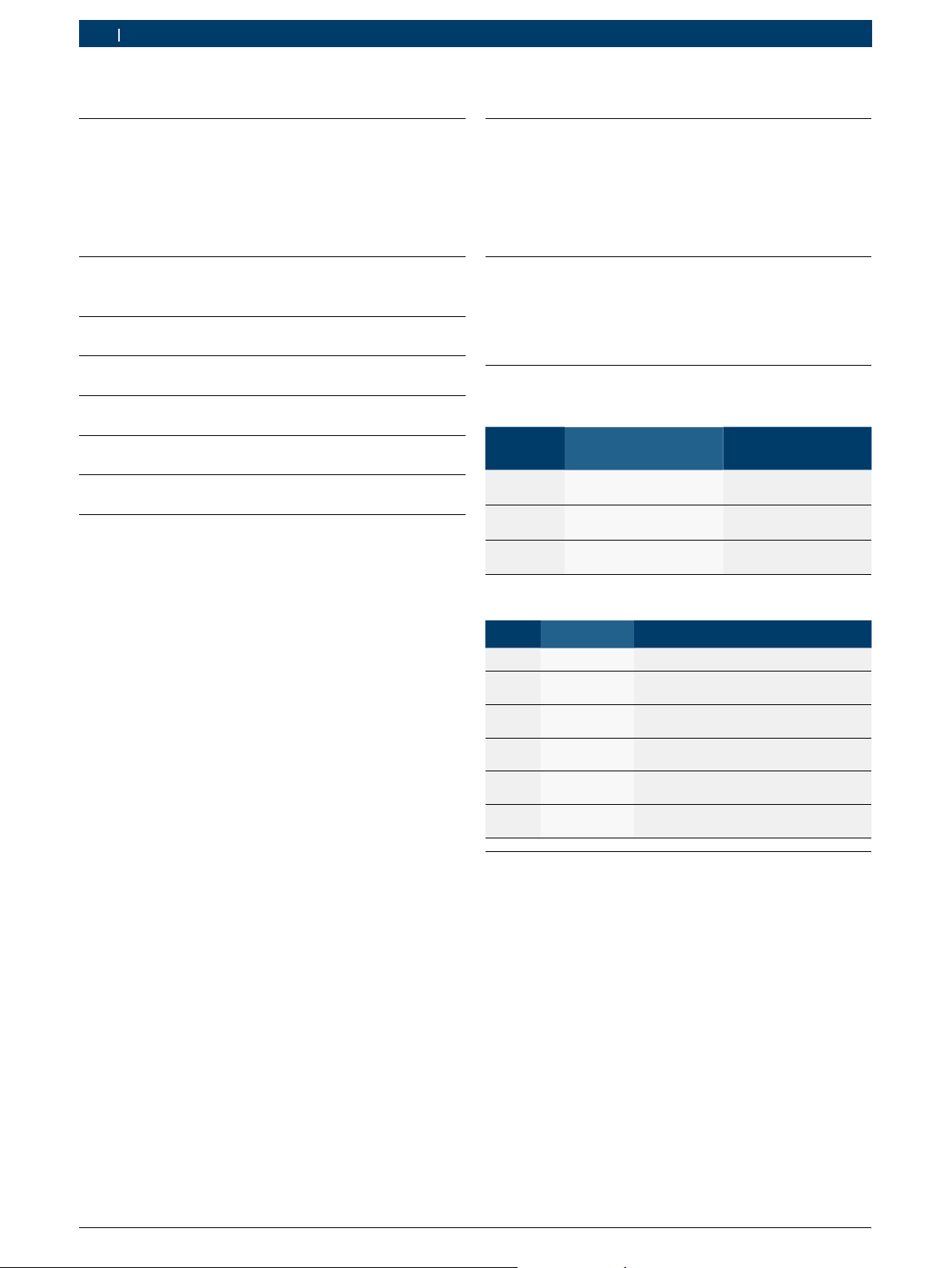
2.1 Zubehör (gesondert zu bestellen)
Bezeichnung Funktion / Bestellnummer
Spannungskonstanter 1 687 022 873
Adapter CRI/CRIN (K) 0 986 613 506
Adapter CRI/CRIN (AK) 0 986 613 507
Adapter CRIN (Klemmen) 0 986 613 508
Hinweise zur Verwendung des Spannungskonstanters:
Beigelegte Netzleitung mit Kaltgerätekupplung gegebenenfalls gegen eine Netzleitung
mit Länder-spezifischen Netzstecker
(100-230 V/ 13A) austauschen. Keinesfalls
Netzadapter, wie z.B. Reiseadapter verwenden!
¶ Netzstromkreis und Netzsteckdose nicht
überlasten, im Zweifelsfall an eine Elektrofachkraft wenden.
3. Umweltschutz
Geben Sie die anfallenden Verpackungsteile zur Wiederverwertung an die entsprechenden Sammelstellen.
Außerhalb der Bundesrepublik Deutschland sind die
entsprechenden Vorschriften des jeweiligen Landes zu
beachten.
4. Sicherheitshinweise
Die folgenden Sicherheitshinweise können nicht
den Anspruch auf absolute Vollständigkeit erheben
und beziehen sich nur auf die unmittelbaren Arbeiten an den Komponenten.
! Die gesetzlichen Unfallverhütungsvorschriften
beachten!
Es wird vorausgesetzt, dass es sich bei den am
System arbeitenden Personen um ausgebildete
Arbeiten richtig und sorgfältig ausgeführt werden!
! Den bestimmungsgemäßen Gebrauch von Syste-
men und Geräten sicherstellen!
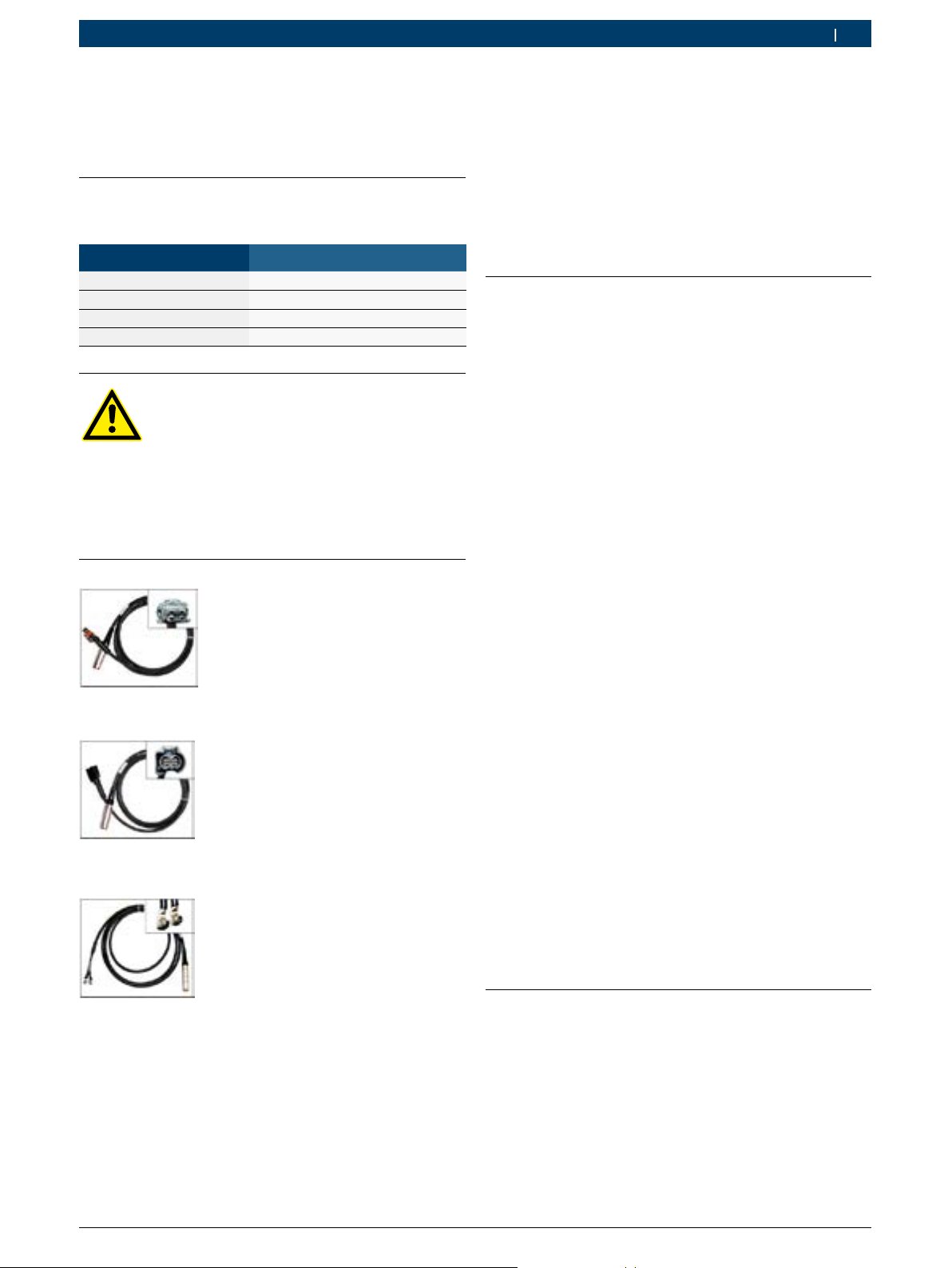
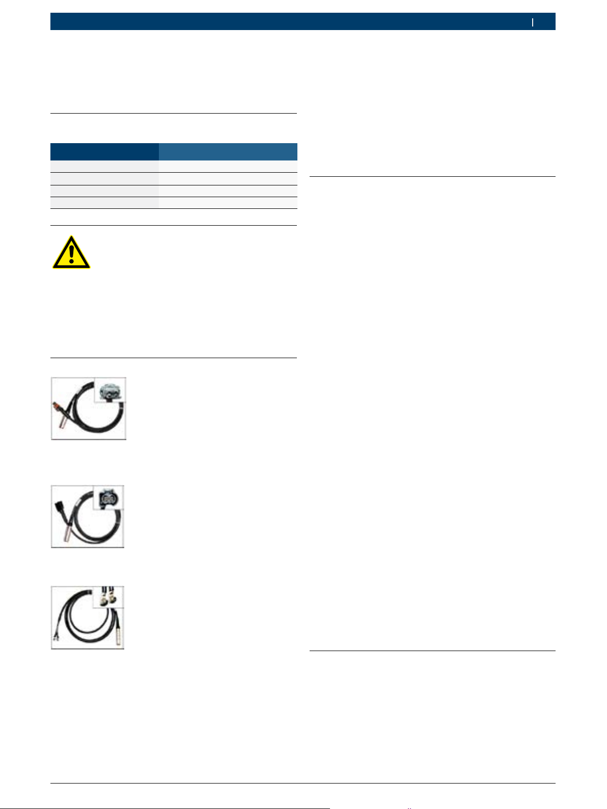
Fig. 1: CRI/CRIN Adapter (K) - 0 986 613 506
Fig. 2: CRI/CRIN Adapter (AK) - 0 986 613 507
Fig. 3: CRIN Adapter (Klemmen) - 0 986 613 508
! An sich bewegenden Teilen besteht höchste Verlet-
Funkenbildung vermeiden!
! Das CRR 220 ausschließlich mit geeignetem Span-
nungskonstanter betreiben 24V DC/ ≥ 20A.
! Der Schutzleiter (PE) am Spannungskonstanter
muss angeschlossen sein.
! Der Anschluss 24 V (-) muss mit dem Schutzleiter
(PE) verbunden sein, hierzu Kapitel 5 (Elektrischer
Anschluss) beachten.
! Beim Anschluss des CRR 220 auf die ordnungs-
gemäße Polung achten, das Gerät darf keinesfalls
verpolt werden.
! Das CRR 220 niemals mit abgenutzten oder defek-
ten Zubehörteilen verwenden.
! Schutzart IP 20: Das Gerät nur im vorgeschriebe-
nen Prüfraum verwenden.
0 986 629 504 2014-02-18| Robert Bosch GmbH
Page 6
6 | CRR 220 | Bestimmungsgemäßer Gebrauch
de
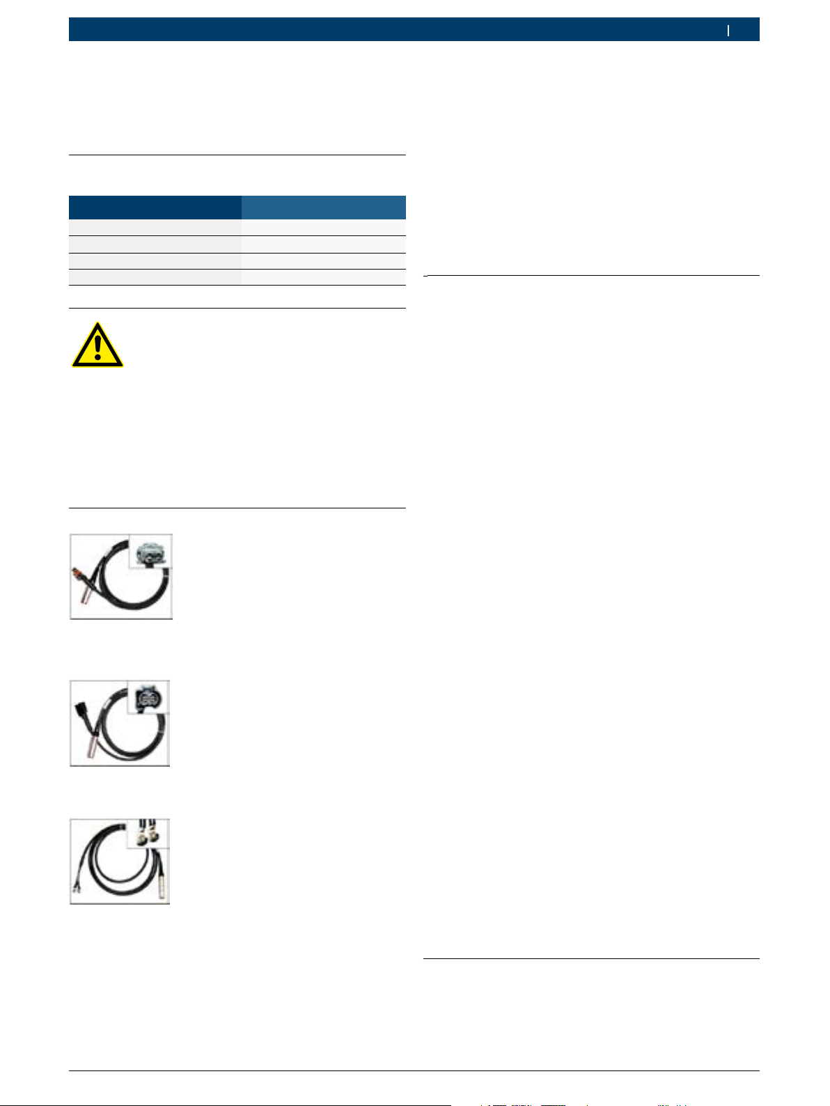
5. Bestimmungsgemäßer Gebrauch
Das Bild zeigt den Prüfaufbau, mit den benötigten Komponenten zur elektrischen Ankerhubmessung an Bosch
Common Rail Injektoren mit Magnetventil.
Fig. 4: Bestimmungsgemäßer Gebrauch
1) Steuergerät für Ankerhubmessung CRR 220
2) Adapterleitung
3) Pneumatik- Steuergerät CRR 120
4) Montagevorrichtung
5) Bosch Magnetventil Injektor
6) Messvorrichtung
7) Digitale Messuhr
! Das CRR 220 ausschließlich zur Ansteuerung von
Bosch Common Rail Injektoren mit Magnetventil
verwenden. Optimale Mess-Ergebnisse können nur
in Verbindung mit dem Spannungskonstanter <Bosch
Bestellnummer:1 687 022 873> garantiert werden.
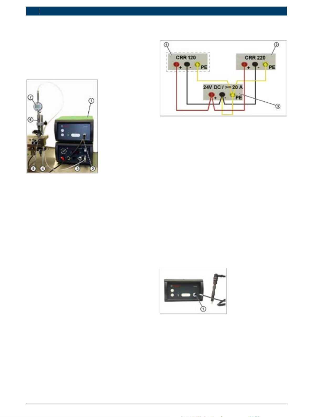
6. Elektrischer Anschluss
Fig. 5: Elektrischer Anschluss
1) CRR 120 (Anschluss Optional)
2) CRR 220
3) Spannungskonstanter (24V DC / ≥ 20A) z.B. Bosch
1 687 022 873
Das Bild zeigt eine schematische Darstellung der Geräterückseite.
Das CRR 220 mit geeigneten Anschlussleitungen, wie
abgebildet an einen Spannungskonstanter anschließen.
Die Kabellänge der Anschlussleitungen darf maximal 2m
(Ø 2,5 mm²) betragen. Optional kann auch das
CRR 120 angeschlossen werden.
! Das CRR 220 darf keinesfalls ohne Schutzleiter (PE)
betrieben werden. Der Anschluss 24 V (-) muss mit
dem Schutzleiter (PE) verbunden sein. Am Ausgang
des CRR 220 ausschließlich die passenden BoschAdapter (Zubehör, Kapitel 1.1) verwenden.
Das Bild (Fig. 6) zeigt die Gerätefrontseite.
! Eine andere oder darüber hinausgehende Benutzung
des CRR 220 gilt als nicht bestimmungsgemäß. Für
hieraus entstehende Schäden wird keine Haftung
übernommen. Garantieleistungen sind in solchen
Fällen ausgeschlossen. Weitere Angaben zum Gebrauch sind der entsprechenden Bosch-Instandsetzungsanleitung zu entnehmen.
Fig. 6: Anschluss für Common Rail Injektor (Adapter notwendig)
Mit Hilfe von passenden Bosch-Adaptern den Injektor
an den Anschluss (Fig. 6, Pos. 1) anschließen.
0 986 629 503 2014-02-18| Robert Bosch GmbH
Page 7

Bedienung | CRR 220 | 7
de
7. Bedienung
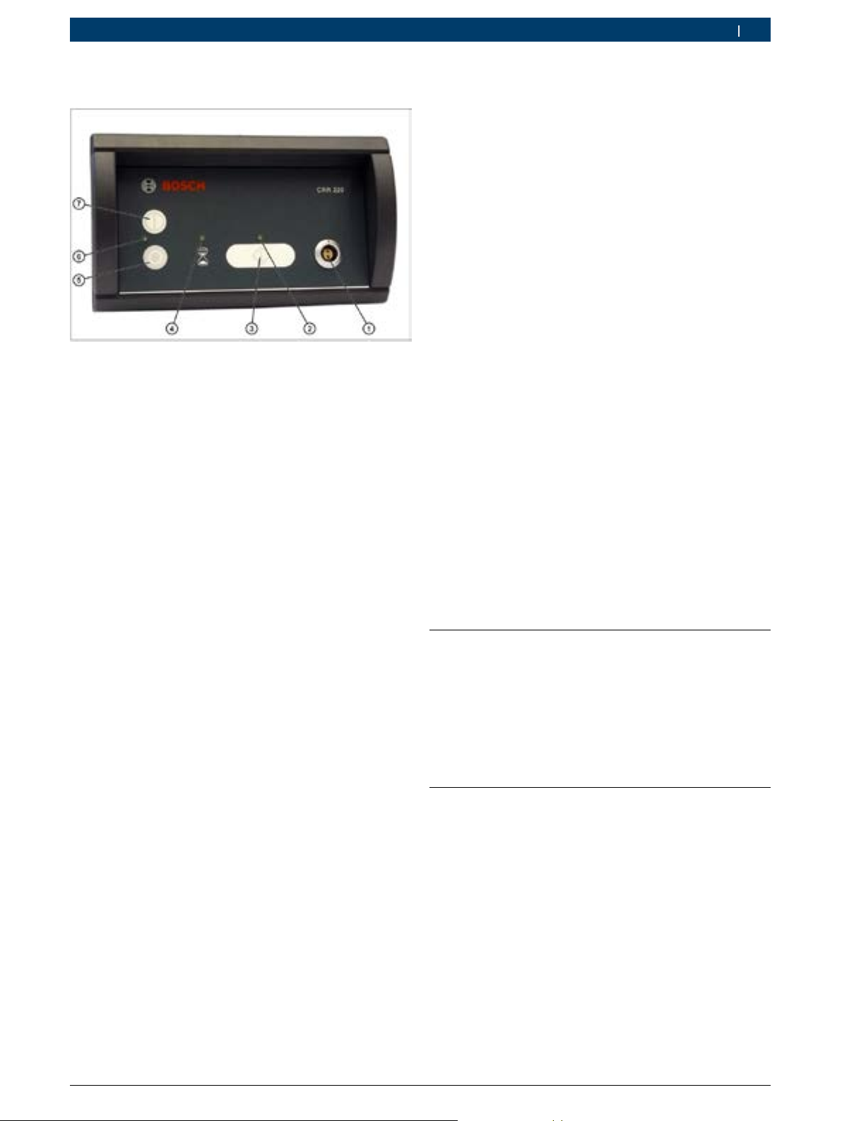
Fig. 7: Bedienung
1) Anschlussbuchse für den Bosch Common Rail Injektor (Adapter
notwendig)
2) LED-Messbereitschaft
3) Taste "Messung"
4) LED-Pause
5) Bedientaste "Aus"
6) LED-Versorgungsspannung
7) Bedientaste "Ein"
Den Spannungskonstanter einschalten und auf 24 V (DC)
regulieren, den Stromregler auf "Maximum" stellen.
Selbsttest des CRR 220:
Nach dem das CRR 220 die Versorgungsspannung
erkannt hat, leuchten als Testfunktion von links nach
rechts jede der drei vorhandenen LED je einmal auf.
Anschließend wird die im Gerät vorhandene SoftwareVersion durch blinken der LED codiert ausgegeben.
Beispielsweise für die Software-Version V01_2_0:
Die LED (6) blinkt einmal, die LED (4) blinkt zweimal
und die LED (2) blinkt nicht.
Nach erfolgreichem Selbsttest blinkt die LED (6). Dies
signalisiert, dass die Versorgungsspannung vorhanden
und das Gerät einschaltbereit ist.
Messung starten:
Die Bedientaste (Fig. 7, Pos. 7) betätigen, das Gerät
wird nun eingeschaltet.
Durch das Leuchten der LED (Fig. 7, Pos. 6) und der
LED (Fig. 7, Pos. 2) wird die Betriebsbereitschaft des
CRR 220 angezeigt.
Nun kann mittels der Taste "Messung" (Fig. 7, Pos. 3)
die Ansteuerung des Common Rail Injektors gestartet
werden.
Nach erfolgreicher Ansteuerung erlischt die LED (Fig. 7,
Pos. 2) und die blinkende LED (Fig. 7, Pos. 4) signalisiert die programmierte Messpause.
! Um die Magnetspulen nicht zu überlasten wird die
Ansteuerung der Injektoren durch das CRR 220 nach
jeder Prüfung um 30 sec. unterbrochen. Dies wird
durch die blinkende LED (4) angezeigt. Eine Manipulation dieser Funktion durch Aus- und Einschalten
des CRR 220 ist nicht zulässig!
Nach absolvierter Messpause stellt das CRR 220 wieder die Betriebsbereitschaft her, dies wird durch die
leuchtende LED (Fig. 7, Pos. 2) angezeigt. Eine weitere
Ansteuerung des Injektors kann nun vorgenommen
werden.
Nach dem Beenden der Messung, das CRR 220 mit der
Bedientaste (5) ausschalten.
8. Beseitigung von Störungen
8.1 Das CRR 220 lässt sich nicht einschalten, die LED (6) leuchtet nicht:
Mögliche Ursachen:
Das CRR 220 wird nicht mit der Betriebsspannung von
24 V (DC) betrieben, bzw. der Spannungsregler am
Spannungskonstanter ist nicht auf 24 V gestellt.
Das CRR 220 wurde verpolt angeschlossen.
8.2 Das CRR 220 steuert den Injektor unzureichend an, bzw. die Ansteuerung
wird abgebrochen.
Mögliche Ursachen:
Der Spannungskonstanter liefert zu wenig Strom für
die Ansteuerung des Injektors, bzw. der Stromregler ist
nicht auf "Maximal" gestellt.
Der Netzstromkreis ist mangelhaft.
0 986 629 504 2014-02-18| Robert Bosch GmbH
Page 8
8 | CRR 220 | Symbols used
en
Contents English
1. Symbols used 8
1.1 In the documentation 8
1.1.1 Warning notices Structure and meaning 8
1.1.2 Symbols in this documentation 8
1.2 On the product 8
2. Scope of delivery 9
2.1 Accessories (to be ordered separately) 9
3. Environmental protection 9
4. Safety instructions 9
5. Intended use 10
6. Spark plug 10
7. Operation 11
8. Fault correction 11
8.1 The CRR 220 cannot be switched on;
LED (6) is not lit: 11
8.2 The CRR 220 does not sufficiently actuate
the Injector or the actuation is stopped. 11
1. Symbols used
1.1 In the documentation
1.1.1 Warning notices - Structure and meaning
Warning notices warn of dangers to the user or people in
the vicinity. Warning notices also indicate the consequences of the hazard as well as preventive action. Warning notices have the following structure:
Warning
symbol
The key word indicates the likelihood of occurrence and
the severity of the hazard in the event of non-observance:
Key word Probability of
DANGER Immediate im-
WARNING
CAUTION Possible dangerous
1.1.2 Symbols in this documentation
Symbol Designation Explanation
!
i
1.
2.
e
"
KEY WORD – Nature and source of hazard!
Consequences of hazard in the event of failure to observe action and information given.
¶ Hazard prevention action and information.
occurrence
pending danger
Possible impending
Severity of danger if in
structions not observed
or severe injury
Death
or severe injury
Death
danger
injury
Minor
situation
Attention Warns about possible property damage.
Information Practical hints and other
Multi-step
operation
One-step
operation
Intermedi
ate result
Final result There is a visible final result on
useful information.
Instruction consisting of several steps.
Instruction consisting of one step.
An instruction produces a vis
ible intermediate result.
completion of the instruction.
-
-
1.2 On the product
Observe all warning notices on products and ensure
!
they remain legible.
0 986 629 503 2014-02-18| Robert Bosch GmbH
Page 9
!
Scope of delivery | CRR 220 | 9
en
2. Scope of delivery
R CRR 220
R Operating instructions (CD-ROM)
2.1 Accessories (to be ordered separately)
Designation Function / order number
Voltage stabilizer 1 687 022 873
Adapter CRI/CRIN (K) 0 986 613 506
Adapter CRI/CRIN (AK) 0 986 613 507
Adapter CRIN (Terminal) 0 986 613 508
Instructions for using the voltage stabiliser:
Replace the enclosed power line with an IEC
plug, if necessary, with a power line with a
country-specific mains plug
(100-230 V/ 13A). Never use AC adapters,
such as travel adapters!
¶ Do not overload the mains supply circuit
and the mains socket, if in doubt, contact
an electrician.
3. Environmental protection
Please take the packaging for recycling to the appropriate collection points. In countries other than Germany,
please consult the appropriate local regulations.
4. Safety instructions
The following safety instructions do not claim to
be exhaustive and only relate to work performed
directly on the components.
! Observe the applicable accident prevention regu-
lations. It is assumed that personnel who work
on the system will be suitably qualified and that
they carry out the work conscientiously and in the
proper manner!
! Make sure that systems and devices are only used
for their intended purpose.
! Shut off the power before disconnecting / connect-
ing wires or connectors. Avoid sparks!
Fig. 1: CRI/CRIN Adapter (K) - 0 986 613 506
Fig. 2: CRI/CRIN Adapter (AK) - 0 986 613 507
Fig. 3: CRIN Adapter (terminals) - 0 986 613 508
! Only operate the CRR 220 with suitable voltage
stabiliser 24V DC/ ≥ 20A.
! The voltage stabiliser's earth wire (PE) must be
connected.
! The 24 V (-) connection must be connected to the
protective earth conductor (PE); refer to Chapter 5
(Electrical Connection).
! Please observe the correct polarity when connect-
ing the CRR 220; the device should never be used
with the polarity reversed.
! Never operate the CRR 220 with worn or defective
accessories.
! Degree of protection IP 20: Only use the device in
the prescribed testing room.
0 986 629 504 2014-02-18| Robert Bosch GmbH
Page 10

10 | CRR 220 | Intended use
en
5. Intended use
The picture shows the test setup, with the necessary
components for the electric anchor stroke measurement of Bosch Common Rail Injectors with a solenoid
valve.
Fig. 4: Intended use
1) Control unit for anchor stroke measurement CRR 220
2) Adapter lead
3) Pneumatic control unit CRR 120
4) Fitting tool
5) Bosch solenoid valve injectors
6) Measuring device
7) Digital dial gauge
! The CRR 220 is intended exclusively for actuating
Bosch Common Rail Injectors with solenoid valve.
Optimal measurement results can only be guaranteed when used with the voltage stabiliser <Bosch
order no: 1 687 022 873>.
6. Spark plug
Fig. 5: Spark plug
1) CRR 120 (spark plug optional)
2) CRR 220
3) Voltage stabiliser (24V DC / ≥ 20A) e.g. Bosch 1 687 022 873
The picture is a schematic representation of the rear
panel.
Connect the CRR 220, as shown, to a voltage stabiliser
using suitable connecting cables. The CRR 120 can also
be connected as an option.
! Never operate the CRR 220 without the earth cable
connected (PE). The 24 V (-) connection must be
connected to the protective earth conductor (PE). At
the output of the CRR 220, the length of the connecting cables must not exceed 2m (Ø 2,5 mm²).
The below picture (Fig. 6) shows the front of the unit.
! Any other or additional use of the CRR 220 is
deemed to contravene the intended use. No liability
will be accepted for any consequential damage. Warranty claims will not be accepted, in such cases. You
will find more details about using the device in the
appropriate Bosch repair instructions.
Fig. 6: Connection for the Common Rail Injector (adapter
Connect the Injector to the spark plug (Fig. 6, Pos. 1),
using suitable Bosch-Adapters.
0 986 629 503 2014-02-18| Robert Bosch GmbH
required)
Page 11
Operation | CRR 220 | 11
en
7. Operation
Fig. 7: Operation
1) Connection socket for the Bosch Common Rail Injector (adapter
required)
2) Ready for measurement LED
3) "Measurement" key
4) Pause LED
5) Control key "Off"
6) Supply voltage LED
7) Control key "On"
Starting the measurement:
Press push-button (Fig. 7, Pos. 7) the device is now
switched on.
By lighting, the LED (Fig. 7, Pos. 6) and the LED (Fig. 7,
Pos. 2) indicate the operational readiness of the
CRR 220.
Now you can start the actuation of the Common Rail
Injector by using the "Measurement" key (Fig. 7, Pos. 3).
After a successful actuation, LED (Fig. 7, Pos. 2) turns
off and the flashing LED (4) indicates the programmed
measurement pause.
! In order not to overload the solenoid coils, the actua-
tion of the Injectors by the CRR 220 is stopped for
about 30 seconds after each test. This is indicated
by LED (4) flashing. Manipulation of this function by
switching the CRR 220 off and on is not permitted!
After the measurement pause, the CRR 220 is ready for
operation again; this is indicated by the LED
(Fig. 7, Pos. 2) lighting. Another actuation of the test
object can now be performed.
Switch on and adjust the voltage stabilizer to 24V (DC),
position the current regulator to "Maximum".
Self-test of the CRR 220:
After the CRR 220 has detected the voltage supply,
each of the three LEDs light once, from left to right, as
a test function.
Subsequently, the software version within the device is
output by coded flashing of the LED.
For example, for the software version V01_2_0:
The LED (6) flashes once, the LED (4) blinks twice and
the LED (2) does not blink.
After a successful self-test, the LED blinks (6). This indicates that the supply voltage is available and the device
can now be switched on.
Once you have finished the measurement, switch the
CRR 220 off with the control key (Fig. 7, Pos. 5).
8. Fault correction
8.1 The CRR 220 cannot be switched on; LED (6) is not lit:
Possible faults:
The CRR 220 is not operated with an operating voltage
of 24 V (DC) or the voltage regulator in the voltage stabiliser is not set to 24V.
The CRR 220 was connected with reverse polarity.
8.2 The CRR 220 does not sufficiently actuate the Injector or the actuation is stopped.
Possible faults:
The voltage stabiliser does not provide enough power
for the actuation of the Injector, or the current regulator
is not set to "Maximum".
The mains power circuit is faulty.
0 986 629 504 2014-02-18| Robert Bosch GmbH
Page 12

12 | CRR 220 | Symboles utilisés
fr
Sommaire français
1. Symboles utilisés 4
1.1 Dans la documentation 4
1.1.1 Avertissements – Conception et
signification 4
1.1.2 Symboles – désignation et
significationxxx 4
1.2 Sur le produit 4
2. Fournitures 5
2.1 Accessoires (à commander séparément) 5
3. Protection de l’environnement 5
4. Consignes de sécurité 5
5. Utilisation conforme 6
6. Raccordement 6
7. Utilisation 7
8. Elimination des défauts 7
8.1 La CRR 220 ne peut être mise en marche,
la LED (6) ne s’allume pas: 7
8.2 La CRR 220 commande l’injecteur de manière
insuffisante ou la commande est interrompue. 7
1. Symboles utilisés
1.1 Dans la documentation
1.1.1 Avertissements – Conception etsignification
Les avertissements mettent en garde contre les dangers
pour l’utilisateur et les personnes présentes à proximité.
En outre, les avertissements décrivent les conséquences
du danger et les mesures préventives. La structure des
avertissements est la suivante :
Symbole
d’avertisse
ment
Le mot clé indique la probabilité de survenue ainsi que
la gravité du danger en cas de non-observation :
Mot clé Probabilité
DANGER Danger direct Mort ou blessure
AVERTISSEMENT
PRUDENCE
1.1.2 Symboles – désignation etsignificationxxx
Symbole Désignation Signification
!
i
1.
2.
e
"
MOT CLÉ - Nature et source du danger !
-
Conséquences du danger en cas de non-observation des mesures et indications.
¶ Mesures et indications pour la préven-
tion du danger.
de survenue
Danger
tiel
Situation po-
poten-
tentiellement
dangereuse
Attention Signale des dommages ma
Information Consignes d'utilisation et autres
Procédure à plu
sieurs étapes
Procédure à
une étape
Résultat in
termédiaire
Résultat final Le résultat final est présen
tériels potentiels.
informations utiles.
Instruction d'exécution d’une opé
ration comportant plusieurs étapes.
Instruction d'exécution d’une opé
ration comportant une seule étape.
Un résultat intermédiaire est vi
sible au cours d’une procédure.
té à la fin de la procédure.
Gravité du danger en
cas de non-observation
corporelle grave
Mort ou blessure
corporelle grave
Blessure
relle légère
corpo-
-
-
-
-
-
1.2 Sur le produit
Observer tous les avertissements qui figurent sur les
!
produits et les maintenir lisibles.
0 986 629 503 2014-02-18| Robert Bosch GmbH
Page 13

!
polarité correcte. Il ne faut en aucun cas inverser la
Fournitures | CRR 220 | 13
fr
2. Fournitures
R CRR 220
R Instructions de service (CD-ROM)
2.1 Accessoires (à commander séparément)
Désignation Numéro Fonction / commande
Stabilisateur de tension 1 687 022 873
Adaptateur CRI/CRIN (K) 0 986 613 506
Adaptateur CRI/CRIN (AK) 0 986 613 507
Adaptateur CRIN (bornes) 0 986 613 508
Remarques concernant l’utilisation du stabilisateur de tension:
Si nécessaire, remplacer le câble secteur
avec accouplement d’appareil froid par un
câble secteur avec fiche spécifique au pays
(100-230 V/ 13 A). N’utiliser en aucun cas
un adaptateur de secteur, comme un adaptateur de voyage, par exemple !
¶ Ne pas surcharger le circuit secteur et
la prise. En cas de doute, contacter un
électricien.
3. Protection de l’environnement
Porter les emballages à recycler à un point de collecte
approprié. En dehors de l'Allemagne, observer la réglementation correspondante du pays en question.
4. Consignes de sécurité
Les consignes de sécurité qui suivent ne prétendent pas être exhaustives et ne concernent que
les travaux effectués directement sur les composants.
! Observer les dispositions légales en matière de
prévention des accidents ! Les personnes effectuant les travaux sur le système doivent être des
professionnels qualifiés et formés et les travaux
doivent être effectués correctement et avec soin !
! Les systèmes et les appareils doivent être utilisés
dans les règles !
! Les pièces en mouvement représentent un risque
important de blessures ! Ne débrancher et ne
brancher les câbles/connecteurs électriques qu'en
l'absence de courant. Eviter la formation d'étincelles !
Fig. 1: Adaptateur CRI/CRIN (K) - 0 986 613 506
Fig. 2: Adaptateur CRI/CRIN (AK) - 0 986 613 507
Fig. 3: Adaptateur CRIN (bornes) - 0 986 613 508
! Utiliser la CRR 220 uniquement avec un stabilisa-
teur de tension approprié 24 V DC/ ≥ 20 A.
! Le conducteur de terre (PE) doit être raccordé au
stabilisateur de tension.
! Le raccord 24 V (-) doit être relié au conducteur de
terre (PE), tenir compte du chapitre 5 (raccordement électrique).
! Veiller à raccorder la CRR 220 en respectant la
polarité de l’appareil.
! Ne jamais utiliser la CRR 220 avec des accessoires
usés ou défectueux.
! Indice de protection IP 20 Utiliser l’appareil unique-
ment dans la salle d’essai prescrite.
0 986 629 504 2014-02-18| Robert Bosch GmbH
Page 14

14 | CRR 220 | Utilisation conforme
fr
5. Utilisation conforme
La figure représente le montage d’essai avec les composants nécessaires à la mesure électrique de la course
d’induit sur les injecteurs à électrovanne de la rampe
commune Bosch.
Fig. 4: Utilisation conforme
1) Centrale de commande pour mesurer la course d'induit CRR 220
2) Cordon adaptateur
3) Centrale de commande pneumatique CRR 120
4) Equipement de montage
5) Injecteur à électrovanne Bosch
6) Instrument de mesure
7) Comparateur numérique
! Utiliser la CRR 220 uniquement pour commander
les injecteurs à électrovanne de la rampe commune
Bosch. Des résultats de mesure optimaux ne peuvent
être garantis qu’en association avec le stabilisateur
de tension <Référence Bosch : 1 687 022 873>.
6. Raccordement
Fig. 5: Raccordement
1) CRR 120 (raccordement en option)
2) CRR 220
3) Stabilisateur de tension (24V DC / ≥ 20A) par ex. Bosch
1 687 022 873
La figure est une représentation schématique du dos de
l’appareil.
Raccorder la CRR 220 à un stabilisateur de tension avec
les câbles de raccordement appropriés comme cela
est représenté. En option, il est également possible de
raccorder la CRR 120.
! La CRR 220 ne doit en aucun cas être utilisée sans
conducteur de terre (PE). Le raccord 24 V (-) doit
être relié au conducteur de terre (PE). A la sortie
de la CRR 220, la longueur maximale des câbles de
raccordement doit être de 2m (Ø 2,5 mm²).
La figure représente la face avant de l’appareil.
! Toute autre utilisation de la CRR 220 est considérée
comme non conforme. Le fabricant décline toute
responsabilité. La garantie est annulée dans un tel
cas. Vous trouverez d’autres indications concernant l’utilisation dans les instructions de réparation
Bosch correspondantes.
Fig. 6: Raccord pour injecteur de rampe commune (adaptateur
A l’aide des adaptateurs Bosch appropriés, raccorder
l’injecteur au raccord (Fig. 6, Pos. 1).
0 986 629 503 2014-02-18| Robert Bosch GmbH
nécessaire)
Page 15

Utilisation | CRR 220 | 15
fr
7. Utilisation
Fig. 7: Utilisation
1) Prise de raccordement pour injecteur de rampe commune Bosch
(adaptateur nécessaire)
2) Disponibilité de mesure LED
3) Touche "Mesure"
4) Pause LED
5) Touche de commande "Arrêt"
6) Tension d’alimentation LED
7) Touche de commande "Marche"
Mettre le stabilisateur de tension en marche et le régler
sur 24 V (DC), positionner le régulateur de courant sur
"Maximum".
Test automatique de la CRR 220:
Dès que la CRR 220 a détecté la tension d’alimentation,
chacune des trois LED disponibles s'allume de gauche à
droite indiquant la fonction de test.
Démarrer la mesure:
Actionner la touche de commande (Fig. 7, Pos. 7), l’appareil est maintenant mis en marche.
L’allumage de la LED (Fig. 7, Pos. 6) et de la LED
(Fig. 7, Pos. 2) indique que la CRR 220 est prête à fonctionner.
Maintenant, la touche "Mesure" (Fig. 7, Pos. 3) permet
de démarrer la commande de l’injecteur de rampe
commune.
La commande étant réussie, la LED (Fig. 7, Pos. 2)
s’éteint et la LED (4) clignote signalant la pause de
mesure programmée.
! Pour ne pas surcharger les solénoïdes, la commande
des injecteurs par la CRR 220 est interrompue pendant 30 s après chaque contrôle. Ceci est affiché par
le clignotement de la LED (4). La manipulation de
cette fonction par l’arrêt el la mise en marche de la
CRR 220 n’est pas autorisée !
Au terme de la pause de mesure, la CRR 220 rétablit la
disponibilité. Ceci est affiché par l’allumage de la LED
(Fig. 7, Pos. 2). Une nouvelle commande de l’éprouvette peut maintenant être effectuée.
Au terme de la mesure, arrêter la CRR 220 avec la
touche de commande (Fig. 7, Pos. 5).
8. Elimination des défauts
Ensuite, la version logiciel disponible dans l’appareil est
émise sous forme codée par le clignotement des LED.
Exemple pour la version logiciel V01_2_0:
La LED (6) clignote une fois, la LED (4) clignote deux
fois et la LED (2) ne clignote pas.
Après exécution réussie du test automatique, la
LED (6) clignote. Ceci signale la présence de la tension
d’alimentation et la disponibilité de l’appareil.
8.1 La CRR 220 ne peut être mise en marche, la LED (6) ne s’allume pas:
Défauts possibles:
La CRR 220 fonctionne avec une tension de service de
24 V (DC) ou le régulateur de tension sur le stabilisateur de tension n’est pas réglé sur 24 V.
La CRR 220 a été raccordée avec une polarité inversée.
8.2 La CRR 220 commande l’injecteur de manière insuffisante ou la commande est interrompue.
Défauts possibles:
Le stabilisateur de tension fournit trop peu de courant
pour commander l'injecteur ou le régulateur de courant
n'est pas réglé sur "Maximum".
Le circuit secteur est défectueux.
0 986 629 504 2014-02-18| Robert Bosch GmbH
Page 16

16 | CRR 220 | Símbolos empleados
es
Índice Español
1. Símbolos empleados 4
1.1 En la documentación 4
1.1.1 Advertencias: estructura y significado 4
1.1.2 Símbolos en esta documentación 4
1.2 En el producto 4
2. Volumen de suministro 5
2.1 Accesorio (pedir por separado) 5
3. Protección del medio ambiente 5
4. Indicaciones de seguridad 5
5. Uso conforme a lo prescrito 6
6. Conexión 6
7. Manejo 7
8. Eliminación de perturbaciones 7
8.1 CRR 220 no se deja conectar, el LED (6) no
está encendido: 7
8.2 CRR 220 activa insuficientemente el inyector
resp. la activación se interrumpe. 7
1. Símbolos empleados
1.1 En la documentación
1.1.1 Advertencias: estructura y significado
Las indicaciones de advertencia advierten de peligros
para el usuario o las personas circundantes. Adicionalmente, las indicaciones de advertencia describen las
consecuencias del peligro y las medidas para evitarlo. Las
indicaciones de advertencia tienen la siguiente estructura:
Símbolo de
advertencia
La palabra clave indica la probabilidad de ocurrencia
del peligro, así como la gravedad del mismo en caso de
inobservancia:
Palabra clave Probabilidad de
PELIGRO Peligro in-
ADVERTENCIA
ATENCIÓN
PALABRA CLAVE – Tipo y fuente del peligro!
Consecuencias del peligro si no se tienen
en cuenta las medidas e indicaciones
mostradas.
¶ Medidas e indicaciones de prevención
del peligro.
ocurrencia
mediato
Peligro ame-
nazante
Posible situa-
ción
peligrosa
Peligro grave en caso de
pasarse por alto
Muerte o lesio-
nes físicas graves
Muerte o lesio-
nes físicas graves
Lesiones
físicas leves
1.1.2 Símbolos en esta documentación
Sím-
Denominación Significado
bolo
Atención Advierte de posibles daños materiales.
!
Información Indicaciones de la aplicación y otras
i
1.2.Acción de
varios pasos
Acción de un
e
solo paso
Resultado
intermedio
Resultado final Al final de una solicitud de acción
"
informaciones útiles
Solicitud de acción compuesta
de varios pasos
Solicitud de acción compuesta de
un solo paso
Dentro de una solicitud de acción se
puede ver un resultado intermedio.
se puede ver el resultado final.
1.2 En el producto
Tenga en cuenta todas las indicaciones de adverten-
!
cia en los productos y manténgalas bien legibles.
0 986 629 503 2014-02-18| Robert Bosch GmbH
Page 17

!
¡En las piezas en movimiento existe máximo peligro
Volumen de suministro | CRR 220 | 17
es
2. Volumen de suministro
R CRR 220
3. Protección del medio ambiente
R Instrucciones de manejo (CD-ROM)
Entregue las diferentes piezas de embalaje para su reci-
2.1 Accesorio (pedir por separado)
Designación Número de función / pedido
Estabilizador de tensión 1 687 022 873
Adapter CRI/CRIN (K) 0 986 613 506
Adapter CRI/CRIN (AK) 0 986 613 507
Adapter CRIN (Terminal) 0 986 613 508
claje en los correspondientes puntos de recogida. Fuera
de la República Federal de Alemania se deben cumplir
las normas correspondientes del respectivo país.
4. Indicaciones de seguridad
Indicaciones para la aplicación del estabilizador de tensión
Sustituir el cable de red adjunto con el
acoplamiento del dispositivo frío eventualmente por un cable de red con enchufe de
red específico del país (100-230 V/ 13A). ¡En
ningún caso utilizar un adaptador de la red,
como p. ej. adaptador de viajes!
¶ No sobrecargar el circuito eléctrico ni el
enchufe de la red; en caso de duda, llamar
un electricista especializado.
Las siguientes indicaciones de seguridad no pretenden estar absolutamente completas y se refieren
sólo a trabajos que se realicen directamente en los
componentes.
! ¡Observar las disposiciones para prevención de
accidentes!
¡Se presupone que las personas que trabajan en el
sistema son colaboradores instruidos formados, y
que los trabajos se ejecutan correctamente y con
cuidado!
Fig. 1: Adaptador CRI/CRIN (K) - 0 986 613 506
Fig. 2: Adaptador CRI/CRIN (AK) - 0 986 613 507
Fig. 3: Adaptador CRIN (bornes) - 0 986 613 508
! ¡Debe garantizarse el uso conforme a lo prescrito
de sistemas y aparatos!
!
de lesiones!
! Los cables/enchufes de cables eléctricos sólo se
deben separar o conectar en un estado sin corriente. ¡Evitar la generación de chispas!
! Operar CRR 220 exclusivamente con un adecuado
estabilizador de tensión 24V DC/ ≥ 20A. El conductor protector (PE) debe estar conectado al estabilizador de tensión.
! La conexión de 24 V (-) debe estar unida con el
conductor protector (PE); al respecto, observar el
capítulo 5 (Conexión eléctrica).
! En la conexión de CRR 220, prestar atención a la
polaridad correcta; el aparato no se debe conectar
en ningún caso con la polaridad invertida.
! No aplicar nunca CRR 220 con acesorios desgasta-
dos o defectuosos.
! Tipo de protección IP 20: Utilizar el aparato sola-
mente en el espacio de comprobación prescrito.
0 986 629 504 2014-02-18| Robert Bosch GmbH
Page 18

18 | CRR 220 | Uso conforme a lo prescrito
es
5. Uso conforme a lo prescrito
La figura muestra el montaje del ensayo, con los componentes necesarios para la medición eléctrica de la
carrera del inducido en inyectores con electroválvula
common rail Bosch.
Fig. 4: Uso conforme a lo prescrito
1) Unidad de mando para la medición de la carrera del inducido
CRR 220
2) Conducción adaptadora
3) Unidad de mando neumática CRR 120
4) Dispositivo de montaje
5) Inyector de electroválvula Bosch
6) Dispositivo de medición
7) Reloj comparador digital
! Utilizar CRR 220 exclusivamente para la activación
de inyectores con electroválvula common rail Bosch.
Resultados de medición óptimos sólo se pueden
garantizar en combinación con el estabilizador de
tensión <Número de pedido Bosch:1 687 022 873>.
6. Conexión
Fig. 5: Conexión
1) CRR 120 (conexión opcional)
2) CRR 220
3) Estabilizador de tensión (24V DC / ≥ 20A) p. ej. Bosch
1 687 022 873
La figura muestra una representación esquemática del
lado dorsal del aparato.
Con cables de conexión adecuados, conectar CRR 220
a un estabilizador de tensión como representado. Opcionalmente se puede conectar también CRR 120.
! CRR 220 no se debe operar en ningún caso sin con-
ductor protector (PE). La conexión de 24 V (-) debe
estar unida con el conductor protector (PE). En la
salida de CRR 220, la máxima longitud de los cables
de conexión debe ascender a como máximo 2m
(Ø 2,5 mm²).
La figura muestra el lado frontal del aparato.
! Un otro uso de CRR 220 o uno que sobrepasa lo
prescrito, rige como uso no conforme a lo prescrito.
Para los daños generados de ello, no se asume la
responsabilidad. Las prestaciones de garantía están
excluidas en tales casos. Indicaciones adicionales
respecto al uso se pueden ver en las correspondientes instrucciones de reparación de Bosch
0 986 629 503 2014-02-18| Robert Bosch GmbH
Fig. 6: Conexión para inyector common rail (adaptador
necesario)
Con la ayuda de adecuados adaptadores Bosch, conectar el inyector a la conexión (Fig. 6, Pos. 1).
Page 19

Manejo | CRR 220 | 19
es
7. Manejo
Fig. 7: Manejo
1) Casquillo de conexión para inyector common rail Bosch (adapta
dor necesario)
2) LED de disposición de medición
3) Tecla "Medición"
4) LED de pausa
5) Tecla de mando "Des."
6) LED de tensión de alimentación
7) Tecla de mando "Con."
Conectar el estabilizador de tensión y regular a 24 V
(CC); poner el regulador de corriente a "Máximo".
Autotest de CRR 220:
Una vez que CRR 220 ha detectado la tensión de alimentación, se enciende cada uno de los tres existentes
LEDs respectivamente una vez de izquierda a derecha
como función de test.
Iniciar la medición:
Accionar la tecla de mando (Fig. 7, Pos. 7); ahora se
conecta el aparato.
Mediante la iluminación de LED (Fig. 7, Pos. 6) y de
LED (Fig. 7, Pos. 2) se indica la disposición de servicio
de CRR 220.
Mediante la tecla "Medición" (Fig. 7, Pos. 3) se puede
iniciar la activación del inyector common rail.
Tras una activación con buen éxito, se apaga el LED
(Fig. 7, Pos. 2) y el parpadeo del LED (4) señaliza, la
pausa de medición programada.
! A fin de no sobrecargar la bobina electromagnética,
tras cada comprobación, CRR 220 interrumpe la
activación de los inyectores durante 30 seg. Esto es
-
indicado por el parpadeo del LED (4). ¡Una manipulación de esta función mediante la desconexión y
conexión de CRR 220 no es admisible!
Tras absolver la pausa de medición, CRR 220 establece
de nuevo la disposición de servicio, que es indicada por
la iluminación del LED (Fig. 7, Pos. 2). Ahora se puede
realizar una nueva activación de la pieza a comprobar.
Después de finalizar la medición, desconectar CRR 220
con la tecla de mando (Fig. 7, Pos. 5).
8. Eliminación de perturbaciones
A continuación, la versión de software existente en el
aparato se emite en forma codificada mediante el parpadeo del LED.
Por ejemplo, para la versión de software V01_2_0:
El LED (6) parpadea una vez, el LED (4) parpadea dos
veces y el LED (2) no parpadea.
Tras un autotest de buen éxito parpadea el LED (6).
Esto señaliza, que existe tensión de alimentación y el
aparato está dispuesto para la conexión.
8.1 CRR 220 no se deja conectar, el LED (6) no está encendido:
Posibles averías:
CRR 220 no se utiliza con la tensión de servicio de
24 V (CC) resp. el regulador en el estabilizador de tensión no está ajustado a 24V.
CRR 220 se ha conectado con la polaridad invertida.
8.2 CRR 220 activa insuficientemente el
inyector resp. la activación se interrumpe.
Posibles averías:
El estabilizador de tensión suministra demasiado poca
corriente para la activación del inyector resp. el regulador de corriente Stromregler no se encuentra en
"Máximo".
El circuito de corriente de la red está defectuoso.
0 986 629 504 2014-02-18| Robert Bosch GmbH
Page 20

20 | CRR 220 | Simboli utilizzati
it
Indice italiano
1. Simboli utilizzati 4
1.1 Nella documentazione 4
1.1.1 Indicazioni di avvertimento –
struttura e significato 4
1.1.2 Simboli nella presente documentazionexxx 4
1.2 Sul prodotto 4
2. Volume di fornitura 5
2.1 Accessori (da ordinare a parte) 5
3. Tutela ambientale 5
4. Avvertenze di sicurezza 5
5. Uso previsto 6
6. Collegamento 6
7. Comando 7
8. Eliminazione di guasti 7
8.1 Non è possibile accendere la CRR 220, il
LED (6) non si illumina: 7
8.2 La CRR 220 effettua un’attivazione
insufficiente dell’iniettore oppure
l’attivazione viene interrotta. 7
1. Simboli utilizzati
1.1 Nella documentazione
1.1.1 Indicazioni di avvertimento – struttura e significato
Le indicazioni di avvertimento mettono in guardia dai
pericoli per l'utente o le persone vicine. Inoltre le indicazioni di avvertimento descrivono le conseguenze del
pericolo e le misure per evitarle. Le indicazioni di avvertimento hanno la seguente struttura:
Simbolo di avvertimento
La parola chiave rappresenta un indice per la probabilità di insorgenza e la gravità del pericolo in caso di mancata osservanza:
Parola
chiave
PERICOLO Pericolo diretto Morte o lesioni fisiche gravi
AVVERTENZA Pericolo potenziale Morte o lesioni fisiche gravi
CAUTELA Situazione potenzial
PAROLA CHIAVE – Tipo e origine del
pericolo.
Conseguenze del pericolo in caso di
mancata osservanza delle misure e delle
avvertenze riportate.
¶ Misure e avvertenze per evitare il peri-
colo.
Probabilità di
insorgenza
mente pericolosa
Gravità del pericolo in caso
di mancata osservanza
Lesioni fisiche lievi
-
1.1.2 Simboli nella presente documentazionexxx
Simbolo Denominazione Significato
!
i
1.
2.
e
"
Attenzione Mette in guardia da po
Nota informativa Indicazioni applicative ed altre
Istruzioni
dettagliate
Istruzioni rapide Istruzioni costituite da una fase.
Risultato
intermedio
Risultato finale Al termine di un’istruzione è
tenziali danni materiali.
informazioni utili.
Istruzioni costituite da più fasi.
All’interno di un’istruzione è vi
sibile un risultato intermedio.
visibile il risultato finale.
-
1.2 Sul prodotto
Rispettare tutti i simboli di avvertimento sui prodotti
!
e mantenere le relative etichette integralmente in
condizioni di perfetta leggibilità!
-
0 986 629 503 2014-02-18| Robert Bosch GmbH
Page 21

!
sono incaricate e che gli interventi vengano eseguiti
della polarità corretta, in nessun caso l’apparecchio
Volume di fornitura | CRR 220 | 21
it
2. Volume di fornitura
R CRR 220
R Istruzioni d’uso (CD-ROM)
2.1 Accessori (da ordinare a parte)
Designazione Numero di funzione / ordine
Stabilizzatore di tensione 1 687 022 873
Adattatore CRI/CRIN (K) 0 986 613 506
Adattatore CRI/CRIN (AK) 0 986 613 507
Adattatore CRIN (morsetti) 0 986 613 508
Avvertenze relative all’impiego dello stabilizzatore di tensione:
All’occorrenza sostituire il cavo di alimentazione elettrica accluso, dotato di connettore
IEC, con un cavo di alimentazione elettrica
dotato di connettore specifico nazionale
(100-230 V/ 13A).
¶ In nessun caso adoperare un adattatore
di collegamento alla rete, come ad es. un
adattatore da viaggio! Non sovraccaricare
il circuito o la presa della rete elettrica, in
caso di dubbio rivolgersi ad un
elettricista.
3. Tutela ambientale
Consegnare le parti della confezione per il riciclaggio ai
rispettivi punti di raccolta differenziata.
Al di fuori della Repubblica Federale Tedesca vanno
rispettate le norme vigenti in materia nel relativo paese.
4. Avvertenze di sicurezza
Le seguenti avvertenze di sicurezza non sono da
considerarsi esaustive e si riferiscono solo ai lavori
effettuati direttamente sui componenti.
! Rispettare le norme antinfortunistiche vigenti! Si
presuppone che le persone che intervengono sul sistema siano operatori specializzati con formazione
idonea ed appositamente istruite per i lavori di cui
a regola d’arte e con la necessaria diligenza!
! Assicurare che sia i sistemi che le apparecchiature
vengano impiegati esclusivamente secondo l’uso
previsto! Sussiste inoltre il pericolo di lesioni causate da parti in movimento!
! Scollegare o collegare i cavi elettrici/connettori
solo nello stato senza corrente. Evitare la formazione di scintille!
Fig. 1: Adattatore CRI/CRIN (K) - 0 986 613 506
Fig. 2: Adattatore CRI/CRIN (AK) - 0 986 613 507
Fig. 3: Adattatore CRIN (morsetti) - 0 986 613 508
! Far funzionare la CRR 220 esclusivamente con uno
stabilizzatore di tensione 24V DC/ ? 20A.
! Il conduttore di protezione (PE) sullo stabilizzatore
di tensione deve essere collegato.
! L’attacco 24 V (-) deve essere collegato con il
conduttore di protezione (PE), rispettare in questo
contesto quanto specificato al capitolo 5 (Collegamento elettrico).
! Durante il collegamento della CRR 220 accertarsi
deve essere collegato con i poli invertiti.
! Non impiegare mai la CRR 220 con accessori usura-
ti o difettosi.
! Grado di protezione IP 20: impiegare l’apparecchio
solo nel locale di prova prescritto.
0 986 629 504 2014-02-18| Robert Bosch GmbH
Page 22

22 | CRR 220 | Uso previsto
it
5. Uso previsto
L’immagine illustra la disposizione di prova con i componenti necessari per la misurazione elettrica della
corsa dell’indotto su iniettori Common Rail di Bosch
con valvola elettromagnetica.
Fig. 4: Uso previsto
1) Centralina per la misurazione della corsa dell’indotto CRR 220
2) Cavo adattatore
3) Centralina impianto pneumatico CRR 120
4) Dispositivo di montaggio
5) Iniettore a valvola elettromagnetica Bosch
6) Dispositivo di misurazione
7) Comparatore digitale
! La CRR 220 va utilizzata esclusivamente per l’at-
tivazione di iniettori Common Rail a valvola elettromagnetica di Bosch. Risultati di misura ottimali
possono essere garantiti solo in combinazione con lo
stabilizzatore di tensione con <codice di ordinazione
Bosch:1 687 022 873>.
6. Collegamento
Fig. 5: Collegamento
1) CRR 120 (collegamento opzionale)
2) CRR 220
3) Stabilizzatore di tensione (24V DC / ≥ 20A) ad es. Bosch
1 687 022 873
La figura mostra una rappresentazione schematica del
lato posteriore dell’apparecchio.
Collegare la CRR 220 tramite cavi di collegamento
adatti ad uno stabilizzatore di tensione, come risulta
dalla figura. In via opzionale può essere collegata anche
la CRR 120.
! In nessun caso la CRR 220 deve essere fatta funzio-
nare senza conduttore di protezione (PE). L’attacco
24 V (-) deve essere collegato con il conduttore di
protezione (PE). All’uscita della CRR 220 la lunghezza massima dei cavi di collegamento deve essere di
2m (Ø 2,5 mm²).
La figura mostra il lato frontale dell’apparecchio.
! Un uso diverso della CRR 220 o un uso che va oltre
quello specificato è da ritenersi non conforme. Per
danni risultanti da un tale uso si declina qualsiasi
responsabilità. In casi del genere è esclusa qualsiasi
prestazione in garanzia. Per ulteriori informazioni in
merito all’uso, consultare le corrispondenti istruzioni
di riparazione Bosch.
Fig. 6: Collegamento all’iniettore Common Rail (adattatore
Con l’aiuto di idonei adattatori Bosch collegare l’iniettore all’attacco (Fig. 6, Pos. 1).
0 986 629 503 2014-02-18| Robert Bosch GmbH
necessario)
Page 23

Comando | CRR 220 | 23
it
7. Comando
Fig. 7: Comando
1) Presa di collegamento per iniettore Common Rail di Bosch (adat
tatore necessario)
2) LED disponibilità alla misurazione
3) Tasto "misurazione"
4) LED pausa
5) Tasto di comando "OFF"
6) LED tensione di alimentazione
7) Tasto di comando "ON"
Accendere lo stabilizzatore di tensione, regolarlo a 24 V
(DC), impostare il regolatore di corrente su "massimo".
Avvio della misurazione:
Azionare il tasto di comando (Fig. 7, Pos. 7), l’apparecchio viene inserito.
L’accensione del LED (Fig. 7, Pos. 6) e del LED (Fig. 7,
Pos. 2) segnala la disponibilità al funzionamento della
CRR 220.
Con il tasto "misurazione" (Fig. 7, Pos. 3) è ora possibile avviare l’attivazione dell’iniettore Common Rail.
Al termine dell’attivazione avvenuta con successo, il
LED (Fig. 7, Pos. 2) si spegne e il lampeggio del LED
(Fig. 7, Pos. 4) segnala la pausa di misurazione programmata.
! Per non sovraccaricare le bobine magnetiche, l’atti-
vazione degli iniettori viene interrotta dalla CRR 220
-
dopo ogni controllo per 30 secondi. Ciò viene segnalato dal lampeggio del LED (4). Non è consentita la
manomissione di questa funzione tramite disinserimento e reinserimento della CRR 220!
Al termine della pausa di misurazione, la CRR 220
ripristina la disponibilità al funzionamento, condizione
segnalata dall’accensione a luce fissa del LED (Fig. 7,
Pos. 2). Ora è possibile proseguire con l’attivazione del
componente sottoposto a prova.
Autotest della CRR 220:
Dopo che la CRR 220 ha riconosciuto la tensione di
alimentazione, come funzione di test ciascuno dei tre
LED lampeggia rispettivamente una volta, da sinistra a
destra.
Successivamente viene emessa la versione software
presente nell’apparecchio, sotto forma di codice di
lampeggio dei LED.
Ad esempio per la versione software V01_2_0:
Il LED (6) lampeggia una volta, il LED (4) lampeggia due
volte e il LED (2) non lampeggia.
Al termine dell’autotest concluso con esito positivo, il
LED (6) lampeggia. Ciò segnala che è presente la tensione di alimentazione e che l’apparecchio è pronto per
essere acceso.
Al termine della misurazione, spegnere la CRR 220 tramite il tasto di comando (Fig. 7, Pos. 5).
8. Eliminazione di guasti
8.1 Non è possibile accendere la CRR 220, il LED (6) non si illumina:
Guasti possibili:
La CRR 220 non viene fatta funzionare con la tensione
di esercizio di 24 V (DC) o il regolatore di tensione sullo
stabilizzatore di tensione non è regolato a 24V.
La CRR 220 è stata collegata con poli invertiti.
8.2 La CRR 220 effettua un’attivazione insufficiente dell’iniettore oppure l’attivazione viene interrotta.
Guasti possibili:
Lo stabilizzatore di tensione fornisce una corrente insufficiente per l’attivazione dell’iniettore oppure il regolatore di corrente non è impostato su "massimo".
Il circuito delle rete elettrica è difettoso.
0 986 629 504 2014-02-18| Robert Bosch GmbH
Page 24

24 | CRR 220 | Använda symboler
sv
Innehållsförteckning svenska
1. Använda symboler 4
1.1 I dokumentationen 4
1.1.1 Varningsanvisningar – Uppbyggnad
ochbetydelse 4
1.1.2 Symboler – Benämning och betydelse 4
1.2 På produkten 4
2. I leveransen ingår 5
2.1 Tillbehör (beställs separat) 5
3. Miljöskydd 5
4. Säkerhetsanvisningar 5
5. Avsedd användning 6
6. Anslutning 6
7. Manövrering 7
8. Avhjälpande av störningar 7
8.1 CRR 220 låter sig inte kopplas på; LED (6)
lyser inte: 7
8.2 CRR 220 adresserar injektorn otillräckligt,
resp. adresseringen avbryts. 7
1. Använda symboler
1.1 I dokumentationen
1.1.1 Varningsanvisningar – Uppbyggnad ochbetydelse
Varningsanvisnignar varnar för faror för användaren eller
personer runt omkring. Därutöver beskriver varningsanvisningar konsekvenserna av faran och åtgärderna
för att undvika den. Varningsanvisningarna har följande
uppbyggnad:
Varningssymbol
Signalordet visar risken för inträdandet samt farlighetsgraden vid missaktning:
Signalord Sannolikhet
FARA Omedelbart ho
VARNING Möjligen hotande fara Dödsfall eller allvarlig
SE UPP Möjligen farlig situation Lätt personskada
1.1.2 Symboler – Benämning och betydelse
Symbol
!
i
1.2.Aktivitet i
e
"
SIGNALORD - Farans typ och ursprung
Farans konsekvenser om de åtgärder och
anvisningar som ges ignoreras.
¶ Åtgärder och anvisningar för att undvika
faran.
att den inträffar
tande fara
Benämning Betydelse
Obs Varnar för möjlig materiell skada.
Information Tips för användningen och annan
flera steg
Aktivitet i
ett steg
Mellan resultat Ett mellanresultat visas inu
Slutresultat I slutet av en uppmaning till ak
-
användbar information.
Uppmaning till aktivitet som
består av flera steg
Uppmaning till aktivitet som
består av ett steg.
ti en uppmaning till aktivitet.
tivitet visas slutresultatet.
Riskens konsekvens om
den ignoreras
Dödsfall eller allvarlig
personskada
personskada
-
-
1.2 På produkten
Beakta alla varningstecken på produkterna och se till
!
att de hålls i läsbart tillstånd.
0 986 629 503 2014-02-18| Robert Bosch GmbH
Page 25
!
Beakta den rätta polvändningen vid anslutningen av
I leveransen ingår | CRR 220 | 25
sv
2. I leveransen ingår
R CRR 220
R Driftinstruktion (CD-ROM)
2.1 Tillbehör (beställs separat)
Beteckning Funktion / beställningsnummer
Spänningskonstanter 1 687 022 873
Adapter CRI/CRIN (K) 0 986 613 506
Adapter CRI/CRIN (AK) 0 986 613 507
Adapter CRIN (klämma) 0 986 613 508
Anvisningar för användning av spänningskonstantern:
Byt om det behövs ut medföljande nätkabel
med anslutningskontakt mot en nätkabel
med lands-specifik nätkontakt (100-230 V/
13A). Använd absolut inte nätadapter, som
t.ex. reseadapter!
¶ Överbelasta inte nätströmkretsen och
nätkontakten; kontakta i tveksamma fall
en elektriker.
3. Miljöskydd
Lämna in förpackningmaterialet för återvinning till behörig mottagningsstation. Utanför Tyskland skall motsvarande föreskrifter för respektive land beaktas.
4. Säkerhetsanvisningar
Följande säkerhetsanvisningar gör inga anspråk på
absolut fullständighet och hänför sig endast till de
omedelbara arbetena på komponenterna.
! Beakta arbetarskyddsföreskrifterna i enlighet med
gällande lag! Det förutsätts, att de personer som
arbetar med systemet är utbildade och instruerade
fackmän som kan utföra arbetena på ett rätt och
omsorgsfullt sätt!
! Se till att systemen och apparaterna används på
ändamålsenligt sätt! Rörliga delar innebär allvarliga
risker för personskada!
! Elektriska ledningar/ledningskontakter får endast
i strömlöst tillstånd tas bort eller anslutas. Undvik
gnistbildning!
Fig. 1: CRI/CRIN Adapter (K) - 0 986 613 506
Fig. 2: CRI/CRIN Adapter (AK) - 0 986 613 507
Fig. 3: CRIN Adapter (klämma) - 0 986 613 508
! CRR 220 får uteslutande drivas med lämplig spän-
ningskonstanter 24V DC/ ≥ 20A.
! Skyddsledaren (PE) på spänningskonstantern
måste vara ansluten.
! Anslutningen 24 V (-) måste vara kopplad till
skyddsledaren (PE), följ anvisningarna i kapitel 5
(Elektrisk anslutning).
!
CRR 220; apparaten får absolut inte kopplas med
felaktig polvändning.
! Använd aldrig CRR 220 med avnötta eller defekta
tillbehörsdelar.
! Kapslingsklass IP 20: Använd apparaten enbart i
föreskrivet testrum.
0 986 629 504 2014-02-18| Robert Bosch GmbH
Page 26

26 | CRR 220 | Avsedd användning
sv
5. Avsedd användning
Bilden visar kontrolluppbyggnaden, med de nödvändiga
komponenterna för frislagsmätning på Bosch Common
Rail injektorer med magnetventil.
Fig. 4: Avsedd användning
1) Styrdon för frislagsmätning CRR 220
2) Adapterkabel
3) Pneumatik- styrdon CRR 120
4) Monteringsanordning
5) Bosch magnetventilinjektor
6) Mätanordning
7) Digital mätklocka
! CRR 220 får uteslutande användas för adressering
av Bosch Common Rail injektorer med magnetventil.
Optimala mätresultat kan endast garanteras tillsammans med spänningskonstanter <Bosch Ordernummer:1 687 022 873>.
6. Anslutning
Fig. 5: Anslutning
1) CRR 120 (anslutning tillval)
2) CRR 220
3) Spänningskonstanter (24V DC / ≥ 20A) t.ex. Bosch
1 687 022 873
Bilden visar en schematisk avbildning av apparatens
baksida.
Anslut CRR 220 med lämpliga anslutningskablar, såsom
avbildats, till en spänningskonstanter. Alternativt kan
även CRR 120 anslutas.
! CRR 220 får absolut inte drivas utan skyddsledare
(PE). Anslutningen 24 V (-) måste vara förbunden
med skyddsledaren (PE). Vid utgången från CRR 220
får anslutningskablarnas längd uppgå till maximalt
2m (Ø 2,5 mm²).
Bilden visar apparatens framsida.
! Annan eller däröver överskridande användning av
CRR 220 anses inte vara enligt föreskrifterna. För
härav uppstående skador tas inget ansvar. Garantiersättning är i sådana fall utesluten. Ytterligare uppgifter för användningen finns i motsvarande Bosch
reparationsanvisning.
Fig. 6: Anslutning för Common Rail injektor (adapter behövs)
Anslut injektorn med hjälp av passande Bosch-adaptrar
till anslutningen (Fig. 6, Pos. 1).
0 986 629 503 2014-02-18| Robert Bosch GmbH
Page 27

Manövrering | CRR 220 | 27
sv
7. Manövrering
Fig. 7: Manövrering
1) Anslutningskontakt för Bosch Common Rail injektor (adapter
behövs)
2) LED-mätberedskap
3) Knapp "Mätning"
4) LED-paus
5) Manöverknapp "Från"
6) LED-matningsspänning
7) Manöverknapp "Till"
Starta mätning:
Aktivera manöverknapp (Fig. 7, Pos. 7) ; apparaten
kopplas nu på.
Genaom att LED (Fig. 7, Pos. 6) och LED (Fig. 7, Pos. 2)
lyser, visas att CRR 220 är driftsklar.
Nu kan med hjälp av knappen "Mätning" (Fig. 7, Pos. 3)
adresseringen av Common Rail injektorn startas.
Efter avslutad adressering slocknar LED (Fig. 7,
Pos. 2) och den blinkande LED (4) signalerar den programmerade mätpausen.
! För att inte överbelasta magnetspolarna, avbryts
adresseringen av injektorerna genom CRR 220 efter
varje kontroll i 30 s. Detta visas genom att LED (4)
blinkar. Det är inte tillåtet att manipulera denna funktion genom att koppla in och ur CRR 220!
Efter absolverad mätpaus återställer CRR 220 driftsberedskapen igen; detta visas genom att LED (Fig. 7,
Pos. 2) lyser. En ytterligare adressering av kontrollobjektet kan nu utföras.
Koppla in spänningskonstantern och reglera den till
24 V (DC); ställ strömreglaget på "Maximum".
Självtest av CRR 220:
Efter det att CRR 220 har identifierat matningsspänningen, lyser som testfunktion var och en av de tre befintliga LED upp en gång från vänster till höger.
Anslutningsvis utges den mjukvaru-version, som finns i
apparaten, kodat genom de blinkande LED-lamporna.
Exempelvis för mjukvaru-version V01_2_0:
LED (6) blinkar en gång, LED (4) blinkar två gånger och
LED (2) blinkar inte.
Efter avslutat självtest blinkar LED (6). Detta signalerar,
att det finns matningsspänning och att apparaten är
klar för inkoppling.
Stäng, efter avslutad mätning, av CRR 220 med manöverknappen (Fig. 7, Pos. 5).
8. Avhjälpande av störningar
8.1 CRR 220 låter sig inte kopplas på; LED (6) lyser inte:
Möjligt fel:
CRR 220 drivs inte med driftspänningen på 24 V (DC),
resp. spänningsregleraren på spänningskonstantern är
inte ställd på 24 V.
CRR 220 har anslutits med fel polvändning.
8.2 CRR 220 adresserar injektorn otillräckligt, resp. adresseringen avbryts.
Möjligt fel:
Spänningskonstantern levererar för lite ström för adresseringen av injektorn, resp. strömregleraren är inte
ställd på "Maximalt".
Nätströmkretsen är bristfällig.
0 986 629 504 2014-02-18| Robert Bosch GmbH
Page 28
28 | CRR 220 | Símbolos utilizados
pt
Índice português
1. Símbolos utilizados 4
1.1 Na documentação 4
1.1.1 Indicações de aviso –
estrutura e significado 4
1.1.2 Símbolos nesta documentação 4
1.2 No produto 4
2. Escopo de fornecimento 5
2.1 Acessórios (pedir separadamente) 5
3. Proteção do meio ambiente 5
4. Instruções de segurança 5
5. Utilização adequada 6
6. Ligação 6
7. Operação 7
8. Eliminação de falhas 7
8.1 Não é possível ligar o CRR 220, o LED (6)
não acende: 7
8.2 O CRR 220 ativa o injetor de modo
insuficiente ou a ativação é interrompida. 7
1. Símbolos utilizados
1.1 Na documentação
1.1.1 Indicações de aviso – estrutura e significado
As indicações de aviso alertam para perigos para o usuário ou pessoas que se encontrem nas imediações. Para
além disso, as indicações de aviso descrevem as consequências do perigo e as medidas de prevenção. As indicações de aviso apresentam a seguinte estrutura:
Símbolo de
advertência
A palavra de advertência indica a probabilidade e gravidade do perigo em caso de desrespeito:
Palavra de
advertên
cia
PERIGO Perigo iminente Morte ou ferimen
AVISO Possível perigo
CUIDADO Possível situa
PALAVRA DE ADVERTÊNCIA - Tipo e
fonte do perigo!
Consequências do perigo em caso de inobservância das medidas e notas mencionadas.
¶ Medidas e indicações para evitar o
perigo.
Probabilidade de
-
ocorrência
iminente
ção de perigo
Gravidade do perigo em caso
de inobservância
tos corporais graves
Morte ou ferimen
tos corporais graves
Ferimentos corporais
-
ligeiros
-
-
1.1.2 Símbolos nesta documentação
Símbolo Designação Significado
!
i
1.
2.
e
"
Atenção Alerta para possíveis danos materiais.
Informação Instruções de utilização e outras
Atuação
mult. passos
Atuação de
passo único
Resultado
intermédio
Resultado
final
informações úteis.
Proposta de atuação com
posta por vários passos
Proposta de atuação composta por
um só passo.
No decorrer de uma proposta de atua
ção é visível um resultado intermédio.
O resultado final fica visível no fim
de uma proposta de atuação.
1.2 No produto
Respeite todos os sinais de aviso nos produtos
!
emantenha-os bem legíveis!
-
-
0 986 629 503 2014-02-18| Robert Bosch GmbH
Page 29

!
Tipo de proteção IP 20: usar o aparelho apenas sala
Escopo de fornecimento | CRR 220 | 29
pt
2. Escopo de fornecimento
R CRR 220
R Instruções de operação (CD-ROM)
2.1 Acessórios (pedir separadamente)
Designação Número da função / fim
Estabilizador de tensão 1 687 022 873
Adaptador CRI/CRIN (K) 0 986 613 506
Adaptador CRI/CRIN (AK) 0 986 613 507
Adaptador CRIN (terminal) 0 986 613 508
Indicações sobre a utilização do estabilizador de tensão:
Se necessário, substitua o cabo de alimentação com o acoplamento de ligação à rede
fornecido por um cabo com uma ficha de
rede específica do país (100-230 V/ 13A).
Nunca utilize um adaptador de rede como p.
ex. um adaptador de viagem!
¶ Não sobrecarregue o circuito de corrente
nem a tomada. Em caso de dúvida, consulte um eletricista.
3. Proteção do meio ambiente
Deposite as embalagens nos respectivos pontos de recolha para serem recicladas. Fora da República Federal
da Alemanha, devem ser respeitadas as respectivas
normas nacionais.
4. Instruções de segurança
As instruções de segurança que se seguem não
pretendem ser completas e dizem apenas respeito
aos trabalhos imediatos nos componentes!
! Respeitar as normas de prevenção contra aciden-
tes! Parte-se do princípio de que as pessoas que
trabalham no sistema são técnicos treinados e especializados e de que os trabalhos são executados
de forma profissional e cuidada!
! Assegure a utilização adequada de sistemas e apa-
relhos! As peças móveis podem causar ferimentos!
! Ligue ou desligue os cabos/conectores de chicote
apenas quando estes não tiverem corrente. Evite a
formação de faíscas!
Fig. 1: Adaptador CRI/CRIN (K) - 0 986 613 506
Fig. 2: Adaptador CRI/CRIN (AK) - 0 986 613 507
Fig. 3: Adaptador CRIN (terminal) - 0 986 613 508
! Operar o CRR 220 exclusivamente com um estabili-
zador de tensão adequado 24V DC/ ≥ 20A.
! O condutor de proteção (PE) tem de estar ligado
no estabilizador de tensão.
! A conexão de 24 V (-) tem de estar ligada ao con-
dutor de proteção (PE), observar a esse respeito o
capítulo 5 (conexão elétrica).
! Na ligação do CRR 220 ter atenção à polaridade
correta, nunca ligue o aparelho com a polaridade
trocada.
! Nunca use o CRR 220 com peças acessórias des-
gastadas ou defeituosas.
!
de ensaio prescrita.
0 986 629 504 2014-02-18| Robert Bosch GmbH
Page 30

30 | CRR 220 | Utilização adequada
pt
5. Utilização adequada
A figura mostra a estrutura de teste, com os componentes necessários para a medição elétrica da elevação
do induzido nos injetores Common Rail da Bosch com
válvula magnética.
Fig. 4: Utilização adequada
1) Unidade de comando para a medição da elevação do induzido
CRR 120
2) Cabo adaptador
3) Unidade de comando pneumática CRR 120
4) Dispositivo de montagem
5) Injetor da válvula magnética Bosch
6) Dispositivo de medição
7) Relógio comparador digital
! Utilize o CRR 220 exclusivamente para a ativação dos
injetores Common Rail da Bosch com válvula magnética. Ótimos resultados de medição só ficam garantidos com a utilização conjunta do estabilizador de
tensão <n.º de referência Bosch:1 687 022 873>.
6. Ligação
Fig. 5: Ligação
1) CRR 120 (conexão opcional)
2) CRR 220
3) Estabilizador de tensão (24V DC / ≥ 20A) p. ex. Bosch
1 687 022 873
A figura mostra uma representação esquemática da parte de trás do aparelho.
Ligue o CRR 220 a um estabilizador de tensão com cabos de ligação adequados, conforme ilustrado. Opcionalmente o CRR 120 também pode ser ligado.
! Nunca opere o CRR 220 sem um condutor de prote-
ção (PE). A conexão de 24 V (-) tem de estar ligada
ao condutor de proteção (PE). À saída do CRR 220,
o comprimento dos cabos de ligação pode perfazer
no máximo 2m (Ø 2,5 mm²).
A figura mostra a parte frontal do aparelho.
! Qualquer outra utilização do CRR 220 que vá para
além dos fins previstos será considerada inadequada. Não nos responsabilizamos pelos danos daí
resultantes. Nesses casos ficam excluídos quaisquer
direitos de garantia. Para outras indicações relativas
à utilização, consulte o respectivo manual de reparo
da Bosch.
0 986 629 503 2014-02-18| Robert Bosch GmbH
Fig. 6: Conexão para o injetor Common Rail (necessário
adaptador)
Com a ajuda de adaptadores adequados da Bosch,
ligue o injetor na conexão (Fig. 6, Pos. 1).
Page 31

Operação | CRR 220 | 31
pt
7. Operação
Fig. 7: Operação
1) Bucha de conexão para o injetor Common Rail da Bosch (neces
sário adaptador)
2) LED de operacionalidade de medição
3) Tecla "Medição"
4) LED de pausa
5) Tecla de operação "Desligado"
6) LED da tensão de alimentação
7) Tecla de operação "Ligado"
Iniciar a medição:
Prima a tecla de operação (Fig. 7, Pos. 7) para ligar o
aparelho.
Com o acender do LED (Fig. 7, Pos. 6) e do LED (Fig. 7,
Pos. 2) é indicada a operacionalidade do CRR 220.
Premindo a tecla "Medição"(Fig. 7, Pos. 3) pode ser
iniciada a ativação do injetor Common Rail.
Após uma ativação bem sucedida, o LED (Fig. 7, Pos. 2)
apaga-se e o LED (4) pisca de modo a sinalizar a pausa
de medição programada.
! De modo a não sobrecarregar as bobines magnéti-
cas, a ativação dos injetores através do CRR 220 é
interrompida durante 30 segundos após cada teste.
Isto é indicado através do piscar do LED (4). Não é
-
permitido manipular esta função, desligando e ligando o CRR 220!
Depois de decorrida a pausa de medição, o CRR 220
restabelece a operacionalidade, a qual é indicada pelo
acender do LED (Fig. 7, Pos. 2). É possível agora ativar
novamente o corpo-de-prova.
Ligue o estabilizador de tensão e regule para 24 V (DC),
coloque o regulador de tensão em "Máximo".
Auto-teste do CRR 220:
Depois de o CRR 220 ter reconhecido a tensão de alimentação, e como função de teste, cada um dos três
LEDs existentes irá acender-se uma vez da esquerda
para a direita.
De seguida, a versão de software existente no aparelho
é emitida de modo codificado através do piscar do LED.
Por exemplo, para a versão de software V01_2_0:
O LED (6) pisca uma vez, o LED (4) pisca duas vezes e
o LED (2) não pisca.
Após um auto-teste bem sucedido, pisca o LED (6).
Este sinaliza que a tensão de alimentação está disponível e o aparelho está pronto a ser ligado.
Depois de terminada a medição, desligar o CRR 220
com a tecla de operação (Fig. 7, Pos. 5).
8. Eliminação de falhas
8.1 Não é possível ligar o CRR 220, o LED (6) não acende:
Possíveis erros:
O CRR 220 não está a ser operado com uma tensão de
serviço de 24 V (DC) ou o regulador de tensão no estabilizador de tensão não está regulado para 24V.
O CRR 220 foi ligado com a polaridade invertida.
8.2 O CRR 220 ativa o injetor de modo
insuficiente ou a ativação é interrompida.
Possíveis erros:
O estabilizador de tensão fornece muito pouca corrente
para a ativação do injetor ou o regulador de tensão não
está regulado para "Máximo".
O circuito de corrente é insuficiente.
0 986 629 504 2014-02-18| Robert Bosch GmbH
Page 32

Robert Bosch GmbH
Diagnostics
Franz-Oechsle-Straße 4
73207 Plochingen
DEUTSCHLAND
www.bosch.com
bosch.prueftechnik@bosch.com
0 986 629 503 | 2014-02-18
 Loading...