

Page 1
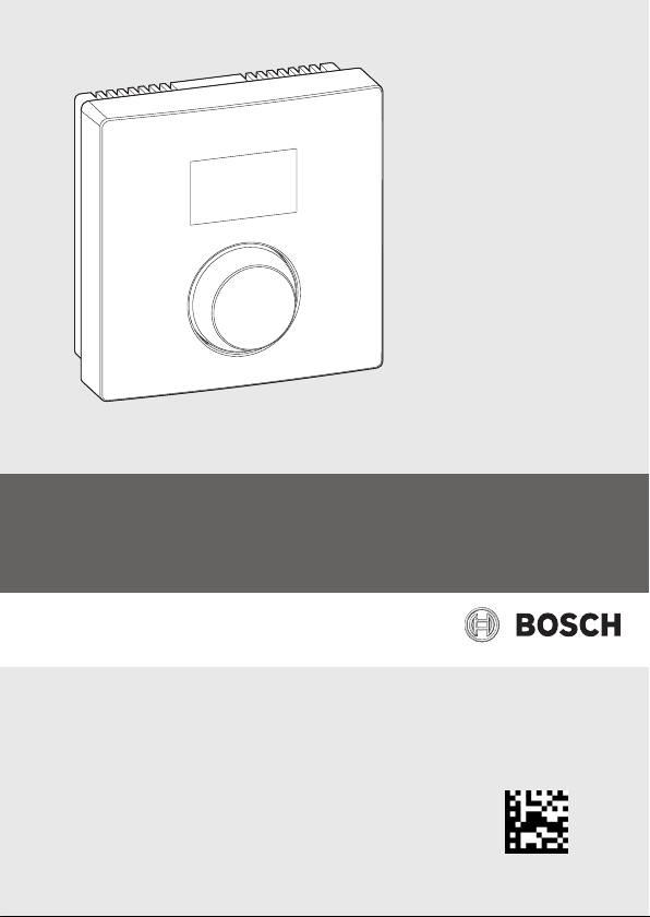
CRC100
Comfort Room Controller 100
6 720 806 769 (2015/01) en
6 720 906 767-00.1O
Page 2

2 | Contents
Contents
1 Explanation of symbols and safety instructions . . . . . . . . . . . . . . . . . . . . . 3
1.1 Explanation of symbols . . . . . . . . . . . . . . . . . . . . . . . . . . . . . . . . . . . . . 3
1.2 Safety instructions . . . . . . . . . . . . . . . . . . . . . . . . . . . . . . . . . . . . . . . . 3
2 Product description . . . . . . . . . . . . . . . . . . . . . . . . . . . . . . . . . . . . . . . . . . . . . 4
2.1 Function as room temperature-dependent controller (A.1 = CO) . . . 5
2.2 Function as zone controller (A.1 = SC) . . . . . . . . . . . . . . . . . . . . . . . . 5
3 Scope of delivery . . . . . . . . . . . . . . . . . . . . . . . . . . . . . . . . . . . . . . . . . . . . . . . 6
4 Technical specifications . . . . . . . . . . . . . . . . . . . . . . . . . . . . . . . . . . . . . . . . . 7
5 Environmental protection/disposal . . . . . . . . . . . . . . . . . . . . . . . . . . . . . . . 8
6 Operation . . . . . . . . . . . . . . . . . . . . . . . . . . . . . . . . . . . . . . . . . . . . . . . . . . . . . 9
7 Energy-saving tips . . . . . . . . . . . . . . . . . . . . . . . . . . . . . . . . . . . . . . . . . . . . . 10
8 Information for installers . . . . . . . . . . . . . . . . . . . . . . . . . . . . . . . . . . . . . . . 11
8.1 Installation on the wall . . . . . . . . . . . . . . . . . . . . . . . . . . . . . . . . . . . . 11
8.2 Power connection . . . . . . . . . . . . . . . . . . . . . . . . . . . . . . . . . . . . . . . . 13
8.3 Commissioning . . . . . . . . . . . . . . . . . . . . . . . . . . . . . . . . . . . . . . . . . . 14
8.4 Settings in the service menu . . . . . . . . . . . . . . . . . . . . . . . . . . . . . . . 15
9 Troubleshooting . . . . . . . . . . . . . . . . . . . . . . . . . . . . . . . . . . . . . . . . . . . . . . . 18
9.1 Temperature-related faults . . . . . . . . . . . . . . . . . . . . . . . . . . . . . . . . 18
9.2 Display of a current fault . . . . . . . . . . . . . . . . . . . . . . . . . . . . . . . . . . . 19
6 720 806 769 (2015/01)CRC100
Page 3
Explanation of symbols and safety instructions | 3
1 Explanation of symbols and safety instructions
1.1 Explanation of symbols
Symbol Function
▶ Sequence of steps
Cross-reference to other points in this document or to other
1.2 Safety instructions
Installation and commissioning
▶ Observe all federal, state and local regulations and standards during installation
and operation!
▶ Observe all instructions to ensure satisfactory operation.
▶ Have the CRC100 installed and commissioned by an authorized heating
contractor only.
▶ Do not install the CRC100 in wet rooms.
▶ Install and commission heat source and other accessories according to the
relevant instructions.
▶ Do not connect the CRC100 to 120 V.
▶ Before installing the CRC100: isolate all poles of heat source and all other BUS
subscribers from the power supply, secure against unintentional reconnection
and make sure the power supply is disconnected.
▶ Electrical components must be installed by a trained electrician and the
installation must meet the National Electric Code as well as all applicable local
codes and regulations.
▶ Install a separate circuit breaker rated at least 15 A for the heating system.
▶ All line voltage wiring must use at least AWG14 size cables.
documents
Flashing display (e. g. flashing 4)
°C
°F
6 720 806 769 (2015/01)
CRC100
Page 4

4 | Product description
Risk of damage from operator error
Operator errors can cause injury and damage to property:
▶ Instruct the customer in the functions and operation of the CRC100.
▶ Make sure that only individuals who can operate the CRC100 correctly have
access to it.
Risk of damage from frost
The heating system can freeze when not in operation:
▶ Leave the heating system on if the outside temperature is below 32 °F (0 °C).
▶ If the CRC100 is used as a controller, system frost protection is not possible.
A CRC100 can provide frost protection for each specific zone connected to. A
CRC100 does not provide frost protection for the heat source or the rest of the
heating systems.
▶ Correct any faults immediately.
2 Product description
• Room temperature-dependent controller (A.1 = CO): The CRC100 can be
used for a heating system with one heating zone. This method of operation is
used when the CRC100 is connected directly to the heat source. This will
modulate the percentage of power output the heat source is supplying.
• Zone controller (A.1 = SC): The CRC100 can be used for one heating zone with
a CZM100. A maximum of 8 heating zones is permitted when connected to
several CZM100. Alternatively the CRC200 may be used instead of a CRC100.
• For heat sources with EMS BUS terminals; Bosch Greenstar Boilers and Buderus
GB Series Boilers. This method of control is used to provide a modulated supply
temperature set point from the room to the heat source.
• The CRC100 can be used as a controller for heat sources with an external
indirect tank and circulator pump, but the DHW maximum temperature and
priority settings are made at the heat source.
• Combination with IPM2, ISM2, ICM, FB100 or FW200 is not possible.
• Some settings are not available, depending on the heat source connected to.
• When connected to CZM100 the CRC100 will have a default WWSD temperature
of 70 °F (21 °C). This setting can be changed if a CRC200 is connected to zone
one of the CZM100 module.
6 720 806 769 (2015/01)CRC100
Page 5

Product description | 5
2.1 Function as room temperature-dependent controller (A.1 = CO)
The CRC100 monitors the room temperature and controls the temperature in the
heat source to produce the required room temperature.
Power output control (P.1 = 5): The power output of the heat source changes
according to the deviation between the current and required room temperature.
There are fewer burner starts and shorter pump runtimes, which saves energy and
enhances the boiler’s and the pump’s lifetime. This control mode is not available,
depeding on the connected heat source.
Supply temperature control (P.1 = 4): The supply temperature changes according
to the deviation between the current and required room temperature. This method
of control is suitable for apartments and residential houses.
2.2 Function as zone controller (A.1 = SC)
The CRC100 can be used as a controller for one of max. 8 heating zones in
combination with CZM100 modules (further information technical
documentation of the CZM100). The control of the zone temperature works equal to
that of the temperature-dependent controller.
6 720 806 769 (2015/01)
CRC100
Page 6
6 | Scope of delivery
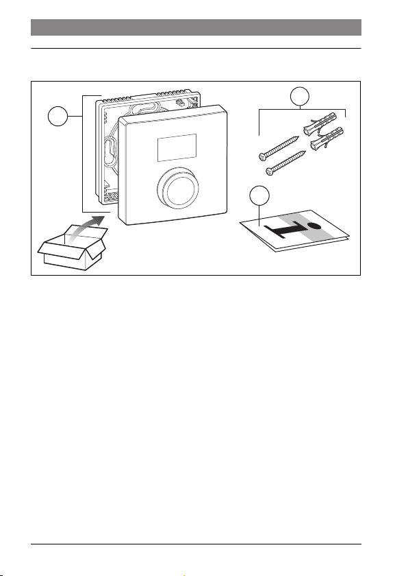
3 Scope of delivery
1
Fig. 1 Scope of delivery
[1] User interface
[2] Technical documentation
[3] Screws and anchors
3
2
6 720 806 769-04.1O
6 720 806 769 (2015/01)CRC100
Page 7
4 Technical specifications
°C
°F
3 1/4"
(82mm)
Technical specifications | 7
3 1/4"
(82mm)
29/32"
(23mm)
1 1/6"
(30mm)
6 720 806 769-05.1O
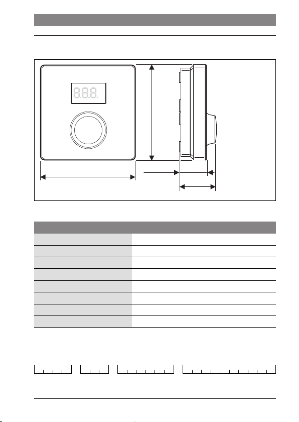
Fig. 2 Dimensions
Technical Data
Dimensions (W × H × D) 3 1/4" x 3 1/4" x 1 1/6" (82 × 82 × 30 mm)
Rated voltage 10 – 24 V DC
Nominal current 4 mA
BUS interface EMS (2-wire BUS)
Control range 41 – 86 °F (5 – 30 °C)
Permiss. ambient temperature 32 – 140 °F (0 – 60 °C)
Protection class III
Protection level IP20
Product ID on the backside of the product (to be entered by the installer). Removal
from wall plate has to be done to look at the ID.
__ _
6 720 806 769 (2015/01)
CRC100
Page 8

8 | Environmental protection/disposal
5 Environmental protection/disposal
Environmental protection is one of the fundamental company policies of the Bosch
Group. We regard quality of performance, economy and environmental protection as
equal objectives.
Environmental protection laws and regulations are strictly adhered to. To protect the
environment, we use the best possible technology and materials taking into account
economic points of view.
Packaging
For the packaging, we participate in the country-specific recycling systems, which
guarantee optimal recycling. All packaging materials used are environmentallyfriendly and recyclable.
Old appliances
Old appliances contain resources that should be recycled.
The components are easy to separate and the plastics are marked. This allows the
various components to be sorted for appropriate recycling or disposal.
6 720 806 769 (2015/01)CRC100
Page 9
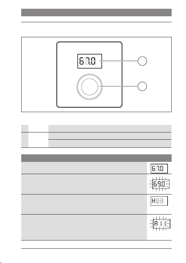
6 Operation
Operation | 9
°C
°F
1
2
6 720 806 767-09.1O
Fig. 3 Overview of control elements
1 Display
2 Dial Turn to choose and change settings.
Press to confirm entry or switch display.
Description of the displays Example
Current room temperature (standard display)
Desired room temperature
▶ Press dial to briefly show the required room temperature
(flashing).
Service display (maintenance required, further information
Installation manual of the boiler)
▶ Press the dial to switch to the standard display.
Fault display with fault code and sub code aternating (further
information chapter 9, page 18 and where applicable installation
manual of the boiler)
▶ Press dial to briefly show the current room temperature.
°C
°F
°C
°F
°C
°F
°C
°F
6 720 806 769 (2015/01)
CRC100
Page 10
10 | Energy-saving tips
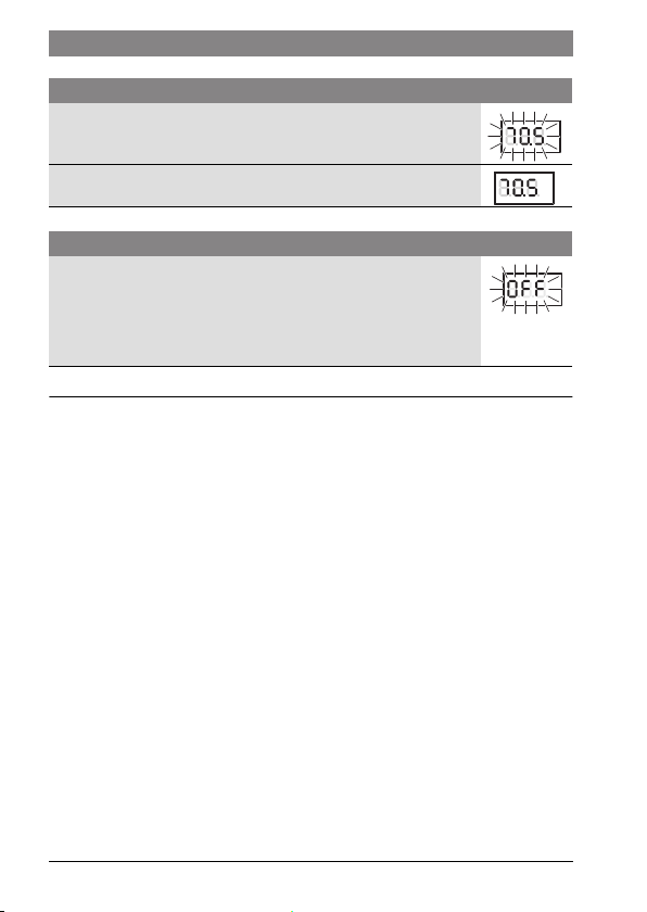
Set the desired room temperature Conclusions
▶ Turn dial in order to set the desired room temperature.
(mind the maximum supply temperature of the heat source)
▶ Press the dial to apply the setting.
°C
°F
°C
°F
Switch off the heating system Conclusions
▶ Turn the dial anti-clockwise to reduce the required room
temperature until OFF shows on the display.
°C
°F
The setting is applied automatically. When the heating is
switched off, frost protection for the room is also switched off.
Frost protection of the heat source (boiler) remains active.
7 Energy-saving tips
• For every 3°F the boiler temperature is reduced, a 1% fuel saving is achieved. For
every 1°F the thermostat is reduced during heating season a 3% fuel savings can
be achieved.
• Zoning allows for less frequently used rooms to be set to a lower temperature
than the common areas. Thus saving energy.
6 720 806 769 (2015/01)CRC100
Page 11
Information for installers | 11
8 Information for installers
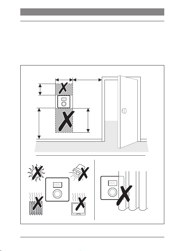
8.1 Installation on the wall
Do not place obstructions within 2 1/2' (0.75 m) below or 1 3/4' (0.5 m) above
CRC100.
▶ Selecting suitable installation location on a flat wall.
≥ 3 1/4'
2'
(≥ 1 m)
°C
°F
1 3/4'
(0.5 m)
(0.6 m)
≥ 4'
(≥ 1.2 m)
°C
°F
2 1/2'
(≥ 0.75 m)
°C
°F
Fig. 4 Selecting suitable installation location on a flat wall
6 720 806 769 (2015/01)
6 720 806 769-01.1O
CRC100
Page 12
12 | Information for installers
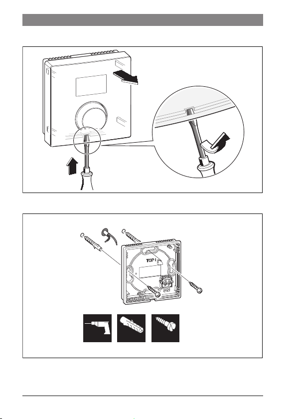
▶ Install CRC100 ( Figures 5 and 6).
3.
1.
Fig. 5 Removing CRC100 from wall base
18-2 AWG (2x 1 mm²)
2.
6 720 647 292-04.1O
15/64"
(6 mm)
Fig. 6 Installing wall base
15/64"
(6 mm)
9/64"
(3,5 mm)
6 720 806 769-02.1O
6 720 806 769 (2015/01)CRC100
Page 13
Information for installers | 13
1
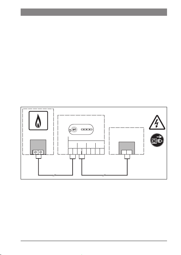
8.2 Power connection
Power is supplied to the user interface via the BUS cable.
▶ Maintain a minimum clearance (4 " / 100 mm) between each of the comfort room
controllers.
▶ Use a cable of at least type AWG 18 (0.75 mm
2
).
▶ Make sure low-voltage cables are routed separately from line voltage cables
(min. clearance 4 " / 100 mm).
▶ If two or more CRC100 are going to be installed, a CZM100 is mandatory. For
further details please refer to the technical documentation of the CZM100.
▶ If the conductor cross-sections are different, use the junction box to connect the
BUS nodes.
Maximum total length of all BUS connections in the system is: 492 ft. (150 m)
▶ Make the BUS connection.
CZM100
CRC100
BUS
1
BUS/BB
1 2
BUSBUS
12
≤ 24 V
BUS BUS
1212
Fig. 7 Making BUS connection between CRC100 and boiler
6 720 806 769 (2015/01)
2
6 720 806 769-03.1O
CRC100
Page 14
14 | Information for installers
8.3 Commissioning
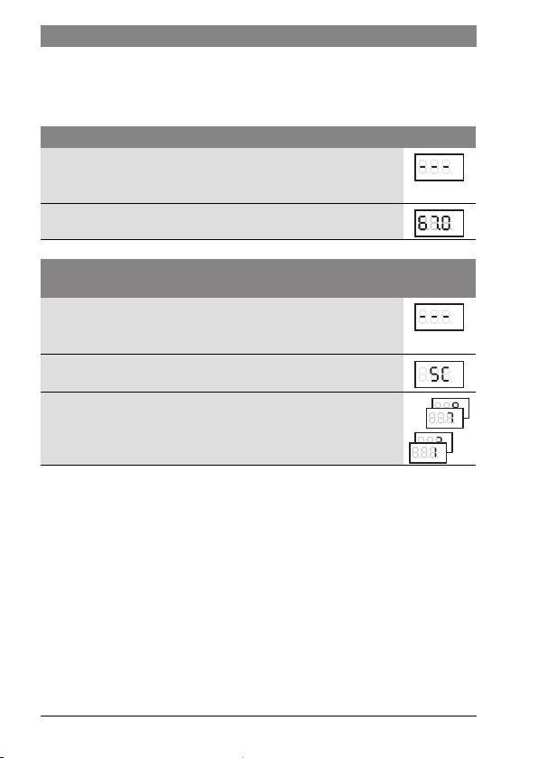
The following tables show first commissioning or commissioning of the user interface
after a reset.
Systems with one heating zone (room controller)
▶ Switch system ON/reset CRC100.
The Display shows 3 dashes, until the connection to the boiler is
established.
No further settings are required. The room temperature is displayed.
Systems with several heating zones (with CZM100 comfort zone manager
installed)
▶ Switch system ON/reset CRC100.
The Display shows 3 dashes, until the connection to the boiler is
established.
1. Set the value “SC” ( chapter 8.4) in code “A.1” and confirm.
2. To set the CRC100 to a specific zone, select the value 1 – 8 in
code “H.C” ( chapter 8.4) and confirm.
°C
°F
°C
°F
°C
°F
°C
°F
°C
°F
°C
°F
. . . .
. . . .
°C
°F
°C
°F
6 720 806 769 (2015/01)CRC100
Page 15
Information for installers | 15
8.4 Settings in the service menu
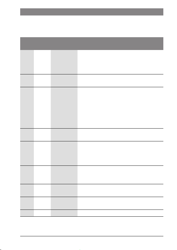
Overview of settings
Default
Control
setting
Code
A.1 SC CO | SC CO: Controller, when communication directly to
H.C 1 1 – 8 Heating Zone options 1 thru 8. Set each CRC to a
d.1 3 2 | 3 | 4 Control Characteristics:
E.1 0.0 – 3.0 ... + 3.0 Calibration setting used to correct any deviation
P.1 4 4 | 5 4- Supply temp control [ °F] means setpoint to
L.1 0 0 | 1 Optimization of pump runtime
C.1 F C | F Unit of Measure to display temperature F = °F or
S.1 – nF.12.01 Software version; information only;
F.1 0 1 | 0 1: Reset to factory default settings
1) Turn the dial to read off the whole value.
range
Description
heat source.
SC: Zone Controller, when connecting to
CZM100 for specific zone control
specific zone.
2 : Fast (2k P range), older home, loose
construction, limited insulation
3 : Average (3k P range), Minimum building
requirements, medium construction
4 : Slow (4k P range), newer home, tight
construction, well insulated
between CRC100 and actual temp.
appliance
5 – Power output [%]; only selectable if “CO”
(controller) is selected in code A.1
0: not active
1: active
C = °C
no adjustments possible
1)
6 720 806 769 (2015/01)
CRC100
Page 16

16 | Information for installers
Reset or power failure
In the event of a reset (with F.1 = 1), the CRC100 goes back to its standard settings,
i. e. it appears after this as a controller for plug & play with all its factory settings.
On restarting after a power failure, the CRC100 appears as the previously configured
user interface, i. e. it is able to appear as a zone controller with the associated
heating zone allocation.
6 720 806 769 (2015/01)CRC100
Page 17
Information for installers | 17
Operation
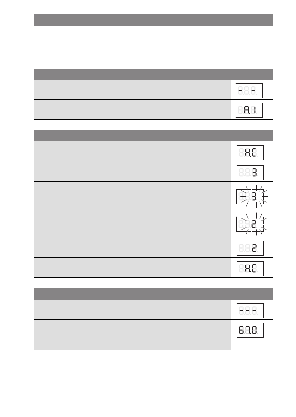
The following tables contain examples showing how to change a value in the service
menu.
Open the service menu Conclusions
1. Press and hold dial until two dashes appear.
2. Release dial to display the first setting.
°C
°F
°C
°F
Changing the setting (e. g. heating zone H.C) Conclusions
1. Turn the dial to select a setting.
2. Press dial to show the current value.
3. Press dial to change the value.
4. Turn dial to set the required value.
5. Press the dial to store the setting.
6. Press and hold dial until the setting is displayed again.
°C
°F
°C
°F
°C
°F
°C
°F
°C
°F
°C
°F
Close the service menu Conclusions
1. Press and hold dial until three dashes appear.
2. Release dial.
The display changes to the standard display, and the user
°C
°F
°C
°F
interface works with the changed setting.
6 720 806 769 (2015/01)
CRC100
Page 18
18 | Troubleshooting
9 Troubleshooting
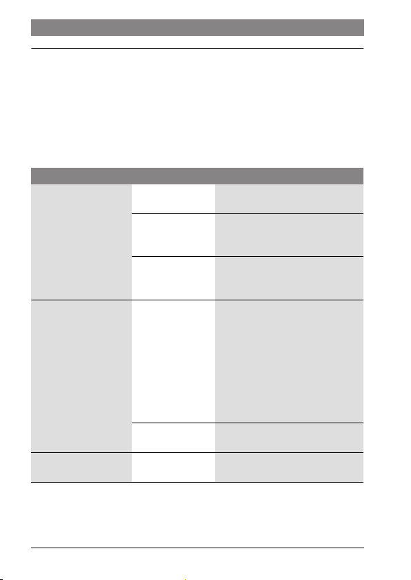
▶ If a fault is displayed, record the fault code and the sub code.
If a fault persists:
▶ Call approved contractor or customer service.
▶ Advise type of fault and ID no. of user interface.
9.1 Temperature-related faults
Problem Cause Remedy
The required room
temperature has not
been achieved.
The room temperature
is higher than the set
value.
The room temperature
fluctuates sharply.
System is air bound
Supply
temperature
Wrong
measurement
Supply
temperature
Installation location
Installation location Have heating contractor move user
Bleed and purge heating system
and heat source.
Set the maximum supply
temperature higher at the heat
source (boiler).
Check E.1 setting; adjust the
deviation between CRC100 and
actual temp.
Confirm the room temperature is
consistently high throughout the
room. Confirm the controller is
installed in a proper location, not
exposed to the sun and you are not
heating the room with other
electrical components. If it is
consistent adjust heating supply
temperature.
Have heating contractor move user
interface to a suitable location.
interface to a suitable location.
6 720 806 769 (2015/01)CRC100
Page 19
Troubleshooting | 19
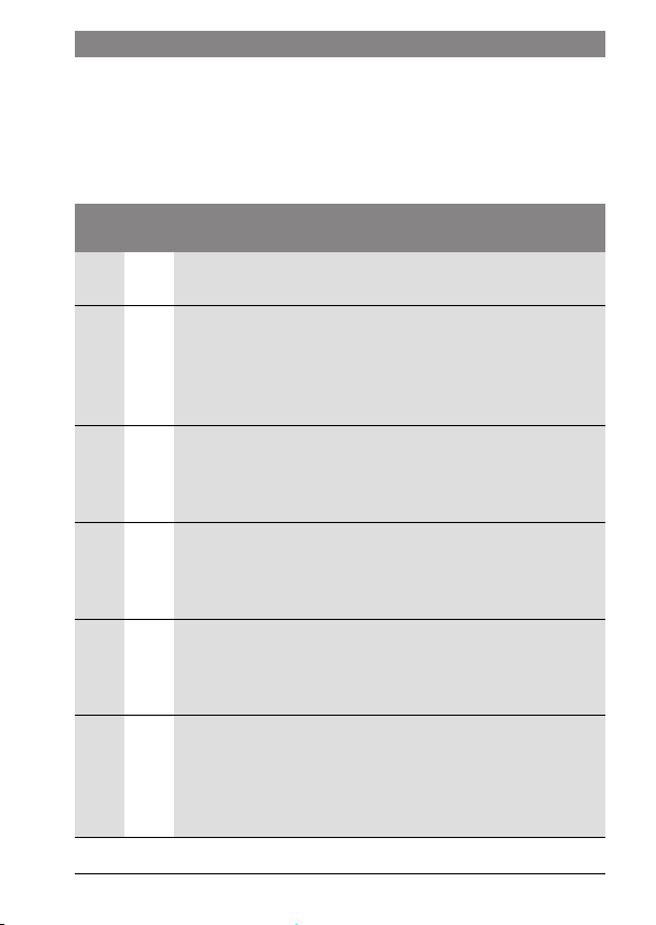
9.2 Display of a current fault
If a fault occurs the display shows the respective fault code and the 3 digit sub code.
In case of 4 digit sub codes, after displaying the fault code the display shows the first
2 digits and then the last 2 digits of the sub code (e. g.: A21 ... 10 ... 01 ... A21 ... 10
...).
Possible causes and
Fault
A12 815 Supply temperature sensor defective.
A31
...
A38
A31
...
A38
A61
...
A68
A61
...
A68
A61 3011 CRC100 with setting for heating zone 1 incorrectly configured.
assistance from the contractor
code
Sub-
code
▶ Replace faulty temperature sensor.
3101
Zone module has no communication to CRCx00 in heating zone y
...
(A31/3101: heating zone 1, ..., A38/3108: heating zone 8).
3108
▶ Set A.1 = SC (zone controller) on corresponding controller.
▶ Set H.C. on corresponding controller according to its heating
zone.
3201
Status on end switch for zone valve is not reasonable. (A31/
...
3201: heating zone 1, ..., A38/3208: heating zone 8)
3208
▶ Check corresponding zone valve and end switch for status and
defects.
1010
No communication via EMS-BUS connection (A61: heating zone 1,
..., A68: heating zone 8).
▶ Connect the controller via a working EMS-BUS cable to a zone
module or a boiler.
1030
Internal data error of the CRC100 (A61: heating zone 1, ...,
1034
A68: heating zone 8). The sub-code corresponds to the data error
1035
type.
1036
▶ Replace faulty CRC100.
▶ If a zone module is installed and recognized, set A.1 = SC (zone
controller).
▶ If only one heating zone is installed, set A.1 = CO (controller).
▶ If the controller is not in zone 1, set H.C. to its correct zone.
6 720 806 769 (2015/01)
CRC100
Page 20
20 | Troubleshooting
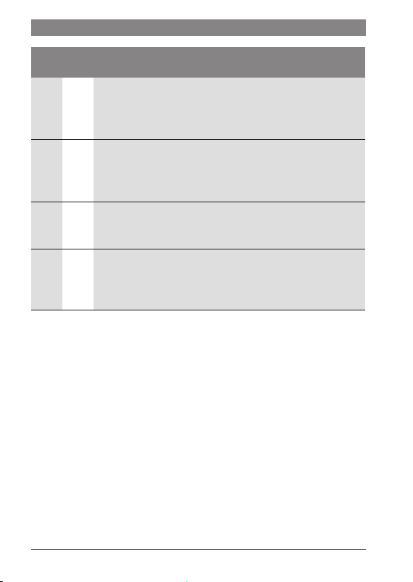
Possible causes and
Fault
A61
...
A68
assistance from the contractor
code
Sub-
code
3011
CRCx00 with heating zone set to y is missing (A61/3011: heating
...
zone 1, ..., A68/3018: heating zone 8).
3018
▶ Check if the corresponding controller is connected.
▶ Set H.C. on each controller according to its heating zone.
3061
A61
...
A68
CRC100 has no communication with zone module (A61/
...
3061: heating zone 1, ..., A68/3068: heating zone 8).
3068
▶ If only one heating zone is installed, set A.1 = CO (controller).
▶ Otherwise check connection between module and controller.
3091
A61
...
A68
Room temperature sensor of the CRC100 defective (A61/
...
3091: heating zone 1, ..., A68/3098: heating zone 8).
3098
▶ Replace faulty CRC100.
Fill - The operating pressure of the heating system is too low.
▶ Add water to heating system through fast fill device (Please
refer to the technical documentation of the heat source/boiler.
Fault code depends on connected heat source.)
6 720 806 769 (2015/01)CRC100
Page 21

Notes
| 21
6 720 806 769 (2015/01)
CRC100
Page 22

22 |
Notes
6 720 806 769 (2015/01)CRC100
Page 23

Notes
| 23
6 720 806 769 (2015/01)
CRC100
Page 24

 Loading...