

Bosch CR 50 Installation Instructions Manual
EMS 2
6 720 809 984-00.1O
User interface
CR50
Installation instructions for contractors
6720856749 (2016/03)
2 | Key to symbols and safety instructions
1 Key to symbols and safety instructions
▶ Observe national and regional regulations, technical rules
and guidelines.
1.1 Explanation of symbols
Warning symbols
Keywords at the start of a warning indicate the type and
seriousness of the ensuing risk if measures to prevent the risk
are not taken.
The following keywords are defined and can be used in this
document:
DANGER:
DANGER indicates a situation that will result in severe injury or
death.
WARNING:
WARNING indicates a situation that could result in severe
injury or death.
CAUTION:
CAUTION indicates a situation that could result in minor to
medium injury.
NOTICE:
NOTICE indicates a situation that could result in damage to
property or equipment.
Important information
The info symbol indicates important information where there is
no risk to people or property.
H Determined use
▶ Only use the product to control solar heating systems in
single-family homes or apartment buildings.
Any other use is considered inappropriate. We take no
responsibility for damage caused through incorrect use.
H Electrical work
Electrical work must only be carried out by a qualified
electrician.
▶ Before starting electrical work:
– Isolate the mains electrical supply and secure against
reconnection.
– Using suitable means, test that the mains voltage is
disconnected.
▶ Never connect the product to mains voltage.
▶ Also observe the connection diagrams of other system
components.
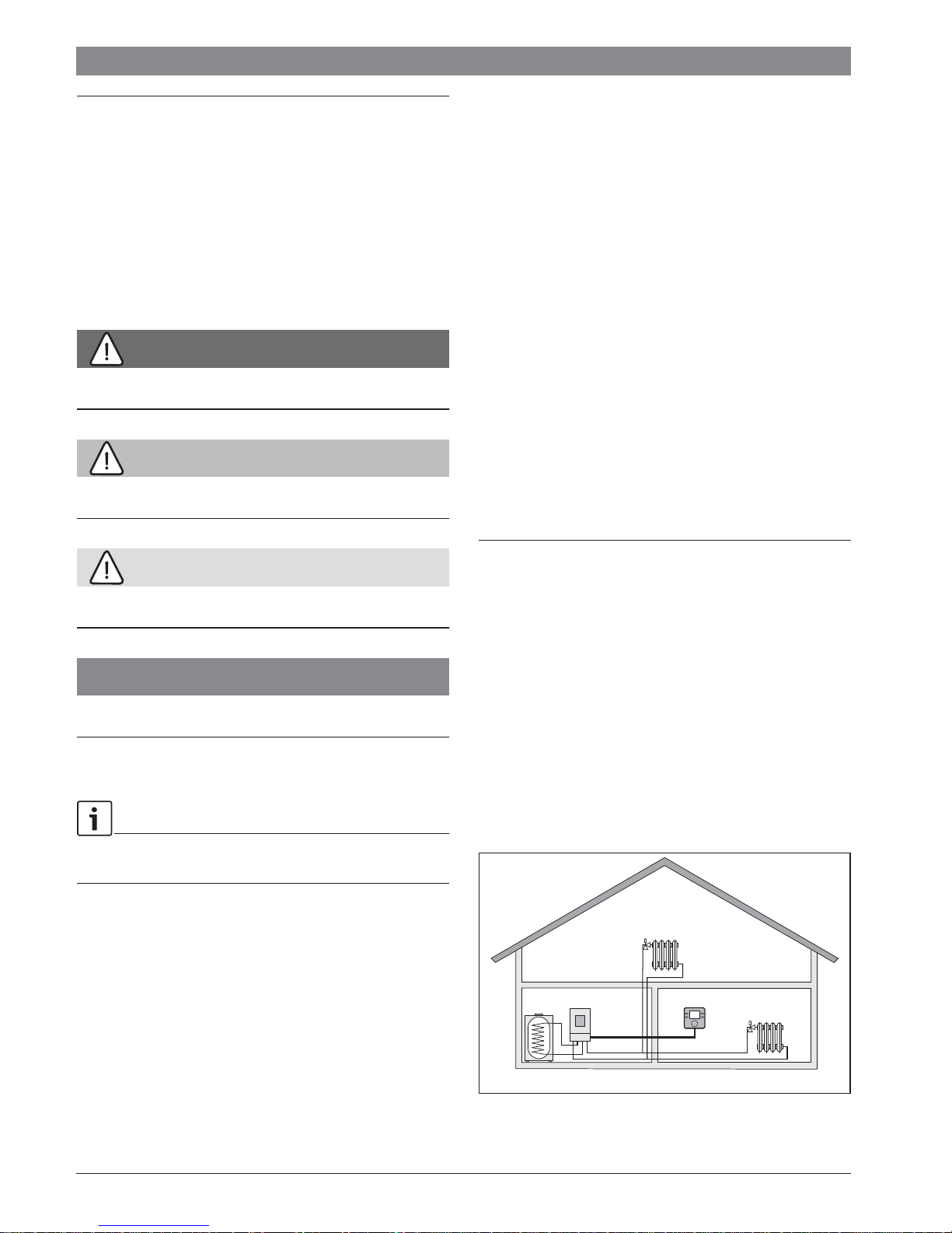
2 Product information
The CR 50 user interface is a control unit without an outdoor
temperature sensor.
Information on energy efficiency (ErP Directive) can be found in
the operating instructions.
2.1 Product description
The user interface is used to control a heating circuit without
mixer and a DHW tank charging circuit for water heating directly
at the heat source.
The user interface is not suitable for connecting the DHW
cylinder behind a low loss header.
The user interface is installed in a suitable living space.
1.2 General safety instructions
H Notice for the target group
These installation instructions are intended for plumbers,
heating engineers and electricians. All instructions must be
observed. Failure to comply with instructions may result in
material damage and personal injury, including possible loss of
life.
▶ Read the installation instructions (heat source, heating
controller, etc.) before installation.
▶ Observe the safety instructions and warnings.
6720856749 (2016/03) CR50
CR 50
0010008714-001
Fig. 1 Example of a heating system with one heating zone
and a CR50 as controller (single-family home)
Installation | 3
B
U
S
B
U
S
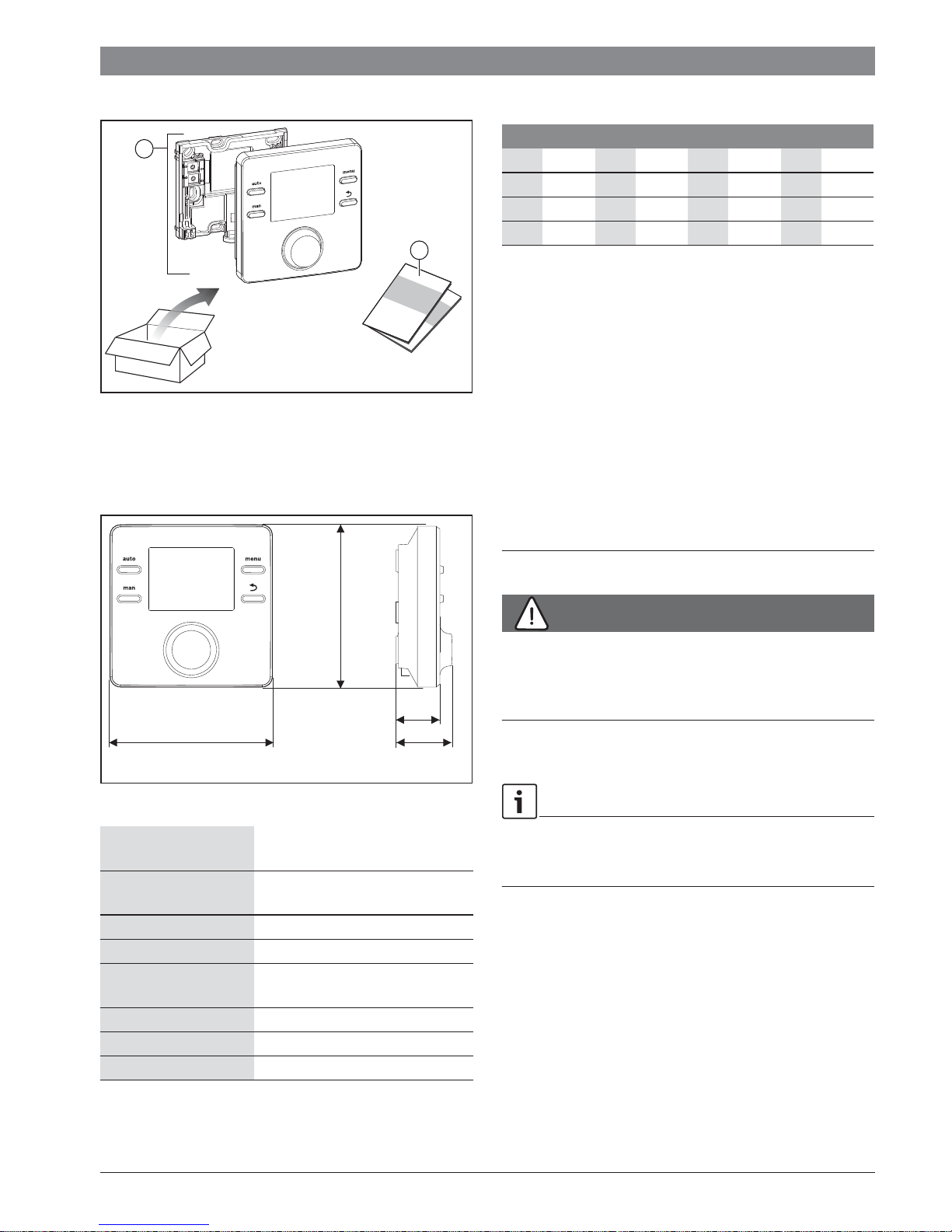
2.2 Scope of delivery
1
Fig. 2 Scope of delivery
[1] User interface
[2] Technical documentation
2.3 Technical data
i
i
2
0010008715-001
2.4 Temperature sensor characteristics
°C : °C : °C : °C :
8 25065 32 9043 56 3723 80 1704
14 19170 38 7174 62 3032 86 1421
20 14772 44 5730 68 2488 – –
26 11500 50 4608 74 2053 – –
Table 2 Resistance values for flow and hot water
temperature sensors
2.5 Applicability of the technical documentation
Information in the technical documentation about heat
sources, heating controllers or the BUS apply also to the
present user interface.
2.6 Additional accessories
No other BUS modules and user interfaces are possible in the
system with the CR 50.
Combination is not possible with the following products:
• FR..., FW..., TR..., TF..., TA...
95
25
95
33
6 720 809 984-08.1O
Fig. 3 Dimensions in mm
Rated voltage 8 ... 16 V DC (2-wire BUS/EMS 2
and OpenTherm)
Rated current 5 ... 23 mA (2-wire BUS/EMS 2 and
OpenTherm)
BUS interface 2-wire BUS, EMS 2, OpenTherm
Control range 5 ... 30 °C
permissible ambient
0 °C ... 50 °C
temperature
Power reserve t4 h
Protection class III
IP-Rating IP20
Table 1 Technical data
3 Installation
DANGER:
Life-threatening danger from electrical shock!
▶ Before installing this product:
Disconnect the heat source and all other BUS nodes from
the mains voltage across all poles.
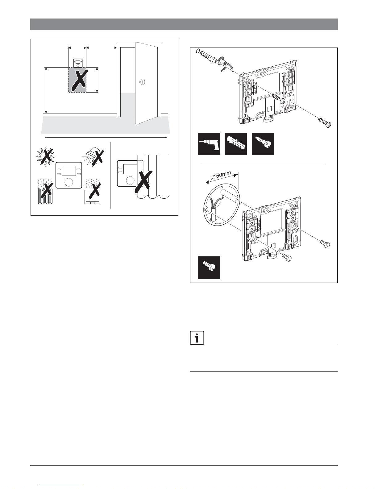
3.1 Installation location
This user interface is intended only for wall-mounted
installation.
Do not install in the heat source or in wet areas.
6720856749 (2016/03)CR50
4 | Installation
≥ 1200
600
≥ 1000
750
3.2 Installation
6 mm 3,5 mm 6 mm
6 720 809 984-03.1O
Fig. 4 Installation location in the reference room
3,5 mm
0 010 003 263-002
Fig. 5 Installation of the plinth
3.3 Electrical connection
Power is supplied to the user interface via the BUS cable. The
wires are insensitive to polarity.
If the maximum total length of the BUS interfaces between all
BUS nodes is exceeded or the BUS system has a ring structure,
commissioning of the system is not possible.
Maximum total length of BUS interfaces:
2
• 50 m at 0.50 mm
• 300 m at 1.50 mm
▶ To avoid inductive interference: Make sure all low-voltage
cables are routed separately from mains voltage cables
(min. clearance 100 mm).
conductor cross-section
2
conductor cross-section.
6720856749 (2016/03) CR50
 Loading...