

Page 1
EMS 2
6 720 646 193-00.2O
CR10
6720830560 (2015/06) div
Page 2

2 | General safety instructions
1 General safety instructions
Installation and commissioning
▶ Observe all country-specific regulations and standards during installation and
operation!
▶ All instructions must be observed. Failure to comply with instructions may result
in material damage and personal injury, including possible loss of life.
▶ Ensure that the user interface is installed and commissioned by an approved
contractor.
▶ Do not install the user interface in wet areas.
▶ Install and commission the heat source and other accessories in accordance with
the relevant instructions.
▶ Never connect the user interface to the 230 V mains.
▶ Before installing the user interface: electrically isolate the heat source and all
other BUS units from the power supply and secure against unintentional
reconnection, making sure that the power supply is completely disconnected.
Damage caused by frost
The system can freeze, if it is not in operation:
▶ Leave the system switched on, if the outside temperature is below 0 °C.
▶ If the user interface is used as a controller, system frost protection is not
possible. System frost protection can only be reliably guaranteed, if weather-
compensated control is used.
▶ Correct any faults immediately.
2 Product Description
Possible applications
• Room temperature-dependent controller for systems with one heating circuit
without mixer
• Zone controller for one heating circuit without mixer but with zone module and
max. 8 heating circuits in systems without a higher-level user interface
6720830560 (2015/06)CR10
Page 3

Product Description | 3
• Remote control in systems with higher-level user interface (e.g. CW 400 with
max. 4 heating circuits or CW 800 with max. 8 heating circuits), can be used
solely as a remote control in conjunction with heat sources with an external
cylinder primary pump
Use
• Heat source with 2-wire BUS system, EMS 2 or OpenTherm
• Combination with timers (e.g. MT10, ...) is possible
• Combination with TR..., TA..., FR... and FW... is not possible.
Scope of delivery
• User interface
• Technical documentation
Technical specifications
Dimensions (W × H × D) 82 x 82 x 23 mm
Rated voltage 10 ... 24 V DC
Rated current 4 mA
BUS interface EMS 2 (2-wire BUS, OpenTherm)
Control range 5 ... 30 °C
Permitted ambient temperature 0 ... 60 °C
Protection class III
IP rating IP20
Product data on energy consumption
The following product data complies with the requirements of EU Regulation 811/
2013 as a supplement to Directive 2010/30/EU. The class of temperature controller
is required to calculate the central heating energy efficiency of an integrated system,
and it is therefore incorporated into the system data sheet.
6720830560 (2015/06)
CR10
Page 4
4 | Product Description
Function Class
1)
[%]
1),2)
CR 10
Room temperature-dependent,
V 3.0 z
modulating
CR 10
& zone module
Room temperature control system with
VIII 5.0 z
t3 temperature sensors (zone control),
modulating
z Delivered condition
1) Classification in accordance with EU Regulation No. 811/2013 for
identification of integrated systems
2) Contribution to seasonal energy efficiency for central heating in %
2.1 Function as room temperature-dependent controller
The CR 10 controls the heat source via the room temperature. Only allowed with
timer in Germany. The user interface is not suitable for controlling heat sources from
other manufacturers with an OpenTherm BUS system (no OpenTherm certificate).
Output control (only 2-wire bus/EMS 2)
The heat output of the heat source changes according to the deviation between the
current and required room temperature. This method of control is suitable for a
uniform temperature level, e.g. open-plan house. There are fewer burner starts and
shorter pump runtimes. This control mode may not be available depending on the
heat source that is connected.
Flow temperature control (2-wire BUS/EMS 2/OpenTherm)
The flow temperature changes according to the deviation between the current and
required room temperature. This method of control is suitable for residential units
and houses with different temperature zones. The accuracy of control is greater and
the flow temperature is limited. This saves fuel.
The pump runtimes can be shortened by means of optimised running of the pump.
6720830560 (2015/06)CR10
Page 5
Operation | 5
2.2 Function as zone controller (only 2-wire BUS/EMS 2)
The CR 10 can be used in conjunction with zone modules without a higher-level user
interface as a controller for max. 8 heating circuits (for further information, see the
technical documentation of the zone module).
The zone temperature is controlled in the same way as with the function of a room
temperature-dependent controller with set flow temperature control.
2.3 Function as remote control (only 2-wire BUS/EMS 2)
The CR 10 can be used as a remote control for a higher-level user interface.
The time program is determined by the higher-level user interface. The required room
temperature can be temporarily changed at the CR 10 until the next switching time of
the time program. After this, the higher-level user interface has priority until the
setting is changed again at the CR 10.
3 Operation
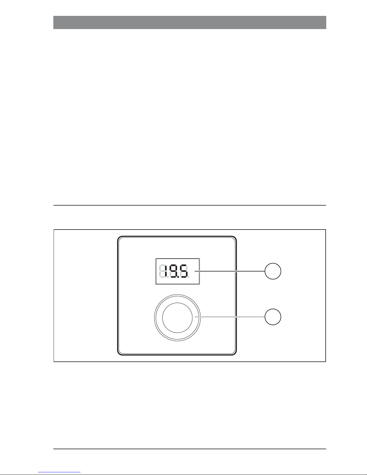
°C
°F
[1] Display
[2] Selector: select (turn) and confirm (press)
1
2
6 720 646 193-09.1O
6720830560 (2015/06)
CR10
Page 6
6 | Information for heating contractor
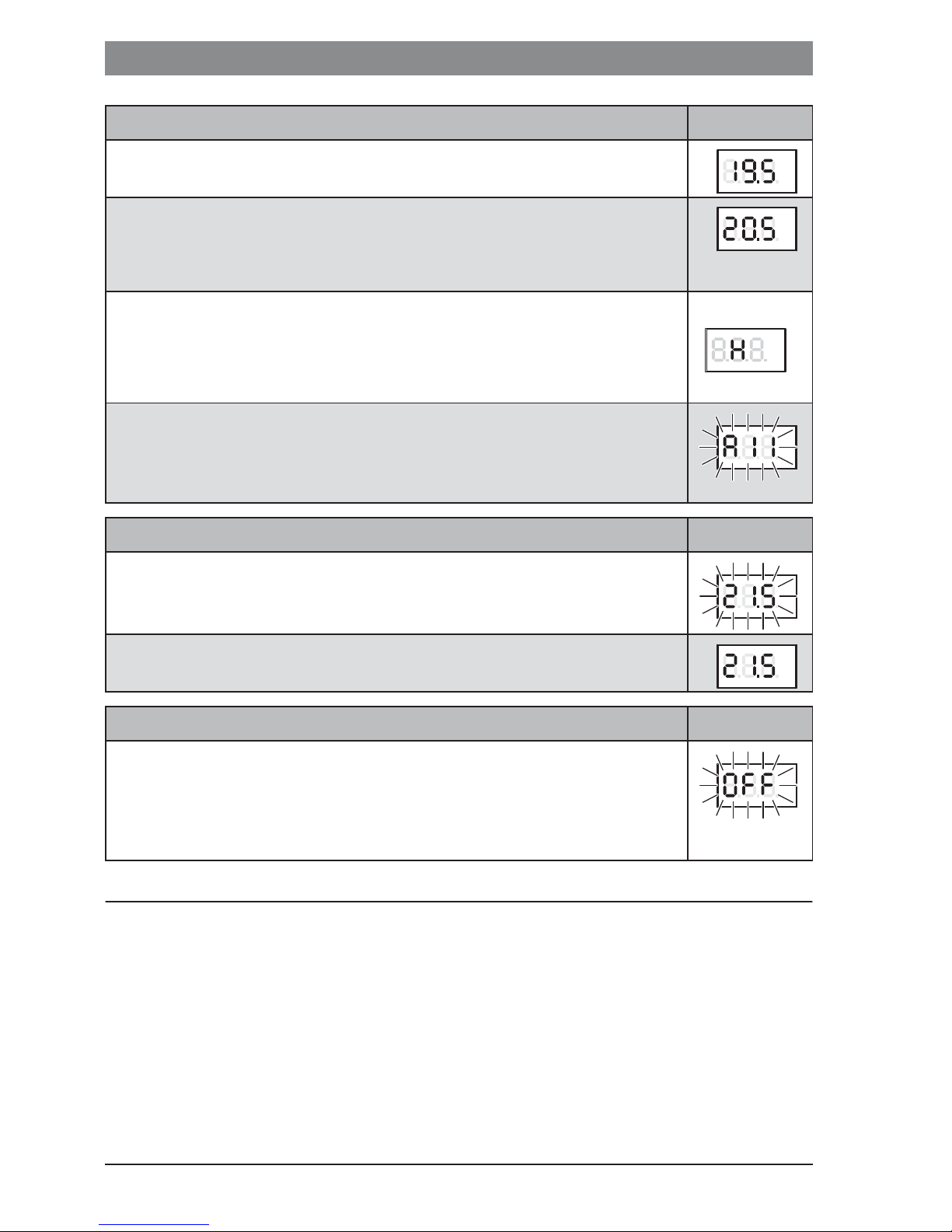
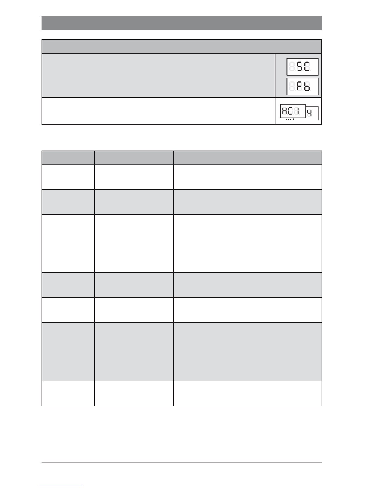
Description of the displays Example
Current room temperature (standard display)
Required room temperature:
▶ Press selector to briefly display the required room temperature
(flashing).
Service display (maintenance required)
▶ Press selector to switch to the standard display.
Fault display alternating between fault code and sub-code
(eliminate Æ faults)
▶ Press selector to briefly display the current room temperature.
Setting the required room temperature Result
▶ Turn the selector to select the required room temperature.
°C
°F
°C
°F
°C
°F
°C
°F
°C
°F
▶ Press the selector to confirm the setting.
Switching off the heating system Result
▶ Reduce the required room temperature until OFF appears.
When the heating system is switched off, frost protection for the
room is also switched off. Frost protection for the heat source
remains active.
4 Information for heating contractor
4.1 Installation
▶ Install the user interface on an even wall (Æ Fig. 1 to 2 from page 22).
4.2 Electrical connection
°C
°F
°C
°F
Power is supplied to the user interface via the BUS cable.
6720830560 (2015/06)CR10
Page 7

Information for heating contractor | 7
Length Recommended cross-
Type of cable
section
d 100 m 0.50 mm
d 300 m 1.50 mm
2
2
At least H05 VV ... (NYM-J...)
Table 1 Permitted BUS cable lengths
▶ Route and connect the BUS cable properly.
▶ Establish the BUS connection (Æ Fig. 3, page 23).
For designation of the BUS terminal, see the technical documentation for the heat
source.
4.3 Connection diagrams with system schematics
The hydraulic diagrams are only schematic illustrations and provide a non-binding
indication of a possible hydraulic circuit.
E.g. Fig. 4, page 24 shows a system schematic for 2 heating circuits without mixer
but with zone module and DHW heating, with individual setting of the 2 CR 10 and
the MZ 100 zone module
4.4 Commissioning
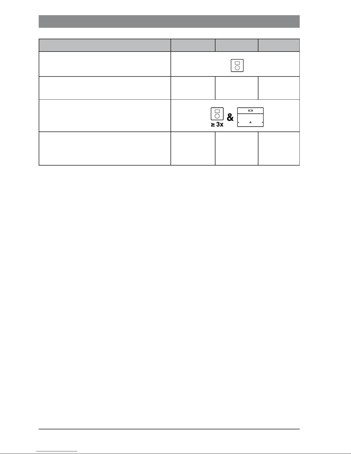
Initial commissioning or commissioning after a reset.
Systems with one heating circuit (room controller)
▶ Switch on the system / reset CR 10.
Three dashes are displayed while the connection is being
established. The room temperature is displayed after the
connection has been established.
Systems with several heating circuits (zone controller/remote control)
▶ Switch on the system / reset CR 10.
Three dashes are displayed while the connection is being
established.
°C
°F
6720830560 (2015/06)
CR10
Page 8
8 | Information for heating contractor
Systems with several heating circuits (zone controller/remote control)
▶ A.1 = Set and confirm SC (zone controller).
-or-
▶ A.1 = Set and confirm Fb (remote control)
▶ Select and confirm heating circuit (HC = 1...8).
°C
°F
4.5 Settings in the service menu
Setting Adjustment range
A.1 CO | Fb | SC Controller (CO), remote control (Fb), zone
HC HC1 | HC2 | ... | HC7 |
HC8
d.1 2 | 3 | 4 Control characteristics (reaction speed)
1)
Description
controller (SC)
Heating circuit/heating zone 1 to 8
2: 2K P range = Quick reaction
2)
°C
°F
°C
°F
°C
°F
3: 3K P range = Medium reaction
4: 4K P range = Slow reaction
E.1 – 3.0 ... 0.0 ... 3.0 Correction value for the room temperature
displayed
P.1 4 | 5 Flow temperature control (4) or output
control (5)
L 1 1 | 0 Optimised running of the pump: in the case
of flow temperature control, the heating
pump runs as briefly as possible.
Switching-off if there is a buffer cylinder in
the system.
C.1 C | F Unit of displayed temperatures °C (C) or °F
(F)
6720830560 (2015/06)CR10
Page 9
Information for heating contractor | 9
Setting Adjustment range
S.1 nF.12.01 Software version
1)
Description
3)
F.1 1 | 0 Reset CR 10
0: Do not reset
1: Reset
1) Values in bold = default setting
2) Only one CR 10 can be allocated to each heating circuit.
3) Turn the selector to read out the whole value.
A reset restores the default setting. In the event of a power failure, the settings
including the heating circuit allocation are retained.
4.6 Operation (example)
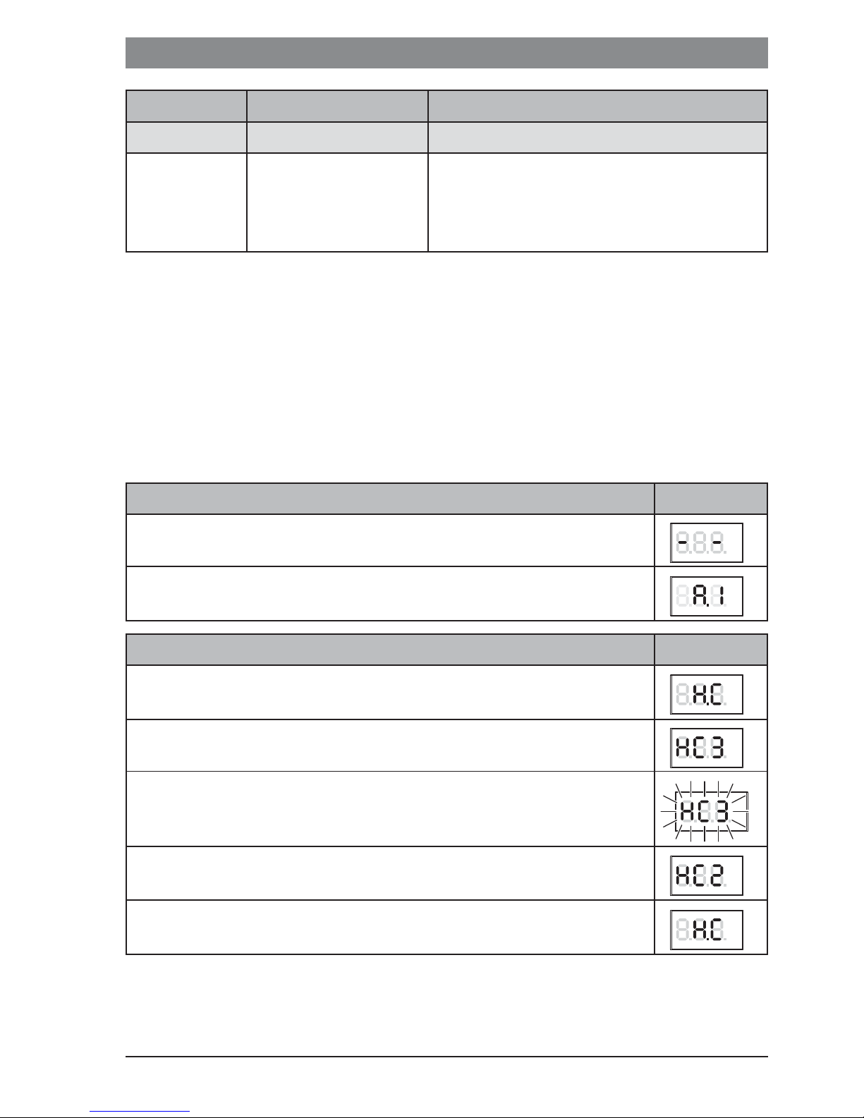
Opening the service menu Result
▶ Press and hold the selector until 2 dashes are displayed.
▶ Release the selector to display the first setting.
Changing the setting (e.g. heating circuit HC) Result
▶ Select the setting.
▶ Press the selector to display the current value.
▶ Press the selector again to change the value.
▶ Select and confirm the required value.
▶ Press and hold the selector until the setting is displayed again.
°C
°F
°C
°F
°C
°F
°C
°F
°C
°F
°C
°F
°C
°F
6720830560 (2015/06)
CR10
Page 10

10 | Eliminating faults
Closing the service menu Result
▶ Press and hold the selector until 3 dashes are displayed.
▶ Release the selector.
The current room temperature is displayed and the user
interface operates with the changed setting.
5 Eliminating faults
If a fault cannot be eliminated, note down the fault code and sub-code:
▶ Contact the approved contractor or Customer Service.
▶ Advise the type of fault and ID no. of the user interface.
__ _
Table 2 ID no. on the rear of the user interface (to be entered by the installer)
°C
°F
°C
°F
If there is a fault, the display shows alternately the fault code and the 3-digit subcode.
In the case of 4-digit sub-codes, initially the first two digits and then the last two
digits are displayed alternately with the fault code (e.g.: A21 ... 10 ... 01 ... A21 ...
10 ... 01 ...).
6720830560 (2015/06)CR10
Page 11

Possible cause and
assistance from the contractor
Eliminating faults | 11
fault code
A61
...
A68
sub-code
3091 ...
3098
Room temperature sensor of the CR 10 defective (A61/
3091: Heating circuit 1, ..., A68/3098: Heating circuit 8).
▶ Replace the CR 10.
A21 1001 CR 10 in Heating circuit 1 incorrectly configured.
▶ If a higher-level user interface (e.g. CW 400) is installed,
set A.1 = Fb (remote control).
▶ If a zone module is installed and recognized, set A.1 = SC
(zone controller).
▶ If no higher-level user interface and only one heating circuit
is installed, set A.1 = CO (controller).
A22
...
A28
1001 BUS signal from the higher-level user interface for remote
heating is missing (A22: Heating circuit 2, ..., A28: Heating
circuit 8).
▶ Install the higher-level user interface (e.g. CW 400).
▶ Establish the BUS connection.
A61
...
A68
A61
...
A68
1081
...
1088
3061
...
3068
CR 10 incorrectly configured (A61/1081: Heating circuit 1, ...,
A68/1088: Heating circuit 8).
▶ Set A.1 = Fb (remote control).
CR 10 incorrectly configured (A61/3061: Heating circuit 1, ...,
A68/3068: Heating circuit 8).
▶ For assistance, see Fault code A21.
Fill - Water pressure in the heating system is too low.
▶ Top up the heating water (even without a contractor,
Æ technical documentation about the heat source).
Table 3 Fault code and sub-code for the contractor
For further information, see the service manual if necessary
6720830560 (2015/06)
CR10
Page 12

12 | Old electrical and electronic appliances
6 Old electrical and electronic appliances
Electrical or electronic devices that are no longer serviceable must
be collected separately and sent for environmentally compatible
recycling (in accordance with the European Waste Electrical and
Electronic Equipment Directive).
To dispose of old electrical or electronic devices, you should use the
return and collection systems put in place in the country concerned.
6720830560 (2015/06)CR10
Page 13

а㡜ᆹޘᨀ⽪ | 13
1 ж㡢ᆿޞᨆ⽰
ᆿ㻻ૂ䈹䈋
▶ 䈧䚥ᆸᡰ൘ഭޣҾᆹ㻵઼䘀㹼Ⲵޣᶑ઼ֻḷ߶DŽ
▶ ᗵ享䚥ᆸᡰᴹ䈤᰾ҖѝⲴᤷ⽪DŽᘭ㿶䈤᰾㜭䙐ᡀ䍒ӗᦏཡ઼Ӫઈ
ՔӑDŽ
▶ 㻵㖞ᗵ享⭡㧧ᗇ䇨ⲴуъӪઈ䘋㹼ᆹ㻵઼䈳䈅DŽ
▶ ࠷ሶ㻵㖞ᆹ㻵൘▞⒯⧟ຳѝDŽ
▶ ᤹➗䈤᰾Җᆹ㻵✝Ⓚ઼ަԆ䱴Ԧᒦሶަᣅޕ֯⭘DŽ
▶ 㻵㖞㔍ሩн㜭䘎᧕ 230 V ⭥㖁DŽ
▶ ᔰᆹ㻵㻵㖞ѻࡽ˖ሶ✝Ⓚ઼ᡰᴹަԆᙫ㓯⭘ᡧޘᯝ⭥ˈ䱢
→ཆ䟽ˈ⺞؍н䙊⭥DŽ
ߦ߱ሲ㠪䇴༽ᦕඅ
䇮༷н䘀㹼ᰦ㜭к߫˖
▶ ᇔཆᓖվҾ 0 °C ᰦࣘ䇮༷DŽ
▶ ྲሶ㻵㖞⭘᧗ࡦಘˈࡉᰐ⌅䱢߫DŽᴹ䟷⭘ᇔཆᓖᝏᓄ᧗
ࡦᯩᔿᰦ㜭؍䇱ᆹޘ䱢߫DŽ
▶ ⭏᭵䳌・ণᧂ䲔DŽ
2 ӝ䈪᱄
ᓊ⭞㜳ᙝ
• ᇚᓜᓊᕅಞ⭘Ҿ䝽༷䶎≤᳆എ䐟Ⲵ䇮༷
• ตಞ⭘Ҿањᑖฏ⁑ඇⲴ䶎≤᳆എ䐟઼ᴰཊ 8 њ䇮༷ѝ
нк㓗㻵㖞Ⲵ᳆എ䐟
• 䘒ぁ⭘Ҿᑖк㓗㻵㖞Ⲵ䇮༷ ˄ֻྲᑖᴰཊ 4 њ᳆എ䐟Ⲵ
CW 400 ᡆ㘵ᑖᴰཊ 8 њ᳆എ䐟Ⲵ CW 800˅ˈоᑖཆ䜘≤㇡ࣘ࣋⌥
Ⲵ✝Ⓚ䝽྇֯⭘ᰦˈ㜭⭘䘌〻᧗ࡦ㻵㖞
ᓊ⭞
• 䝽༷ৼ㓯ᙫ㓯ǃ EMS 2 ᡆ OpenTherm ᙫ㓯㌫㔏Ⲵ✝Ⓚ
• оᇊᰦಘ㓴ᓄ⭘ ˄ֻྲ MT10 ㅹ˅
6720830560 (2015/06)
CR10
Page 14

14 | ӗ૱䈤᰾
• н᭟ᤱо TR...ǃ TA...ǃ FR... ઼ FW... 䝽྇֯⭘
ב䍝㤹പ
• 㻵㖞
• ᢰᵟ᮷ẓ
ᢶᵥᮦᦤ
ቪረ ˄ᇭ × 儈 × ␡˅ 82 x 82 x 23 mm
仍ᇊ⭥
仍ᇊ⭥⍱
ᙫ㓯᧕
䈳᧗㤳ത
ݱ䇨Ⲵ⧟ຳᓖ
䱢ᣔ㓗࡛
䱢ᣔㅹ㓗
10 ~ 24 V DC
4 mA
EMS 2 ˄ৼ㓯ᙫ㓯ˈ OpenTherm
5 ~ 30 °C
0 ~ 60 °C
III
IP20
㜳㙍ӝᮦᦤ
лࡇӗ૱ᮠᦞㅖ 2010/30/EU ⅗ⴏᤷԔⲴ 811/2013 㺕ݵ⌅ԔⲴ㾱
≲DŽ䇑㇇༽䇮༷Ⲵᇔ䟷᳆㜭Ⓚ᭸⦷ᰦ䴰㾱֯⭘᧗ಘⲴ㓗࡛ˈ䈕㓗
࡛䇠ᖅ൘㌫㔏ᮠᦞ亥ѝDŽ
ࣕ㜳 㓝ࡡ
1)
[%]
1),2)
CR 10
ᇔᝏᓄˈ䈳ࡦ
CR 10
& ฏ⁑ඇ
䝽༷ t3 њᓖՐᝏಘ ˄ฏ᧗
ࡦ˅Ⲵᇔ᧗ࡦ㌫㔏ˈ䈳ࡦ
z Ӕ䍗⣦ᘱ
1) ㊫࡛ㅖ⅗ⴏ 811/2013 ⌅ԔޣҾ༽䇮༷ḷ䇶Ⲵ䈤᰾
2) ᒤᓖᇔ䟷᳆㜭᭸ᮠ٬ᱮ⽪ѪⲮ࠶ᮠ
V 3.0 z
VIII 5.0 z
6720830560 (2015/06)CR10
Page 15

ӗ૱䈤᰾ | 15
2.1 ⭞֒ᇚᓊᕅಞ
CR 10 䙊䗷ᇔᓖ䈳᧗✝ⓀDŽᗧഭӵݱ䇨֯⭘ᇊᰦಘDŽ㻵㖞н䘲
Ҿ᧗ࡦަԆࡦ䙐୶⭏ӗⲴ䝽༷ OpenTherm ᙫ㓯㌫㔏Ⲵ✝Ⓚ ˄ᰐ
OpenTherm 䇱Җ˅DŽ
ࣕ⦽ δӻ䲆㓵ᙱ㓵 /EMS 2ε
✝ⓀⲴ✝࣏⦷Պṩᦞᖃࡽᇔ઼⨶ᜣᇔѻ䰤Ⲵٿᐞ䘋㹼᭩DŽ䈳᧗㹼
Ѫ䘲⭘Ҿ㔏аⲴᓖ≤ᒣˈֻྲ䟷⭘ᔰ᭮ᔿ㔃ᶴⲴᡯ䰤DŽ䘉߿ቁ⟳✗
ಘⲴࣘ⅑ᮠˈ㕙⸝⌥Ⲵ䘀㹼ᰦ䰤DŽߣҾ䘎᧕Ⲵ✝Ⓚˈ䘉⿽᧗ࡦᯩᔿ
㜭н⭘DŽ
䟽࠰≪ᓜ δ㓵ᙱ㓵 /EMS 2/OpenThermε
䟷᳆ࠪ≤ᓖṩᦞᖃࡽᇔ઼⨶ᜣᇔѻ䰤Ⲵٿᐞ䘋㹼᭩DŽ᧗ࡦ㹼Ѫ
䘲⭘ҾᓖฏཊṧⲴትᡰ઼ᡯ䰤DŽ᧗ࡦ㋮ᓖᴤ儈ˈ䟷᳆ࠪ≤ᓖ
䲀DŽ䘉ṧԕ㢲ⴱ⟳ᯉDŽ
䙊䗷Ո⌥䘀㹼ԕ㕙⸝⌥Ⲵ䘀㹼ᰦ䰤DŽ
2.2 ⭞֒ตಞ δӻ䲆㓵ᙱ㓵 /EMS 2ε
CR 10 оฏ⁑ඇ㓴֯⭘ˈнᑖк㓗㻵㖞ˈѪ᧗ࡦಘ⭘Ҿ䈳
᧗ᴰཊ 8 њ᳆എ䐟 ˄䈖㓶ؑ䈧৲䰵ฏ⁑ඇⲴᢰᵟ᮷ẓ˅DŽ
䈳᧗ฏᓖо֯⭘䇮ᇊⲴ䟷᳆ࠪ≤ᓖ᧗ࡦᮠᦞⲴᇔᝏᓄᔿ᧗ࡦ
ಘˈҼ㘵Ⲵ⭘⨶DŽ
2.3 ⭞֒䘒ぁ㻻㖤 δӻ䲆㓵ᙱ㓵 /EMS 2ε
CR 10 ԕ⭘к㓗㻵㖞Ⲵ䘌〻᧗ࡦ㻵㖞DŽ
䙊䗷к㓗㻵㖞䇮㖞ᰦ䰤〻ᒿDŽ൘ CR 10 кԕ⸝ᰦᴤ᭩⨶ᜣᇔˈ
ла⅑࠷ᦒᰦ䰤〻ᒿᰦཡ᭸DŽѻк㓗㻵㖞䟽ᯠѫሬˈⴤ㠣⅑൘
CR 10 кᴤ᭩䇮㖞DŽ
6720830560 (2015/06)
CR10
Page 16

16 |
3 ᬃ֒
°C
°F
1
2
6 720 646 193-09.1O
[1] ᱮ⽪ቿ
[2] 䘹ᤙ᤹䫞˖䘹ᤙ ˄䖜˅઼⺞䇔 ˄᤹˅
ᱴ⽰ᮽᵢ䈪᱄ ⽰ׁ
ᖃࡽᇔ ˄唈䇔ᱮ⽪˅
⨶ᜣᇔ˖
▶ ᤹䘹ᤙ᤹䫞ˈ⸝ᰦᱮ⽪⨶ᜣᇔ ˄䰚⛱˅DŽ
㔤ᣔᱮ⽪ ˄䴰㾱؍ޫ˅
▶ ᤹䘹ᤙ᤹䫞ˈ࠷ᦒ㠣唈䇔ᱮ⽪DŽ
䘋㹼᭵䳌ᱮ⽪ᰦˈӔᴯᱮ⽪᭵䳌ԓ⸱઼䱴࣐⸱ ˄Æ ᧂ䲔
᭵䳌˅
▶ ᤹䘹ᤙ᤹䫞ˈ⸝ᰦᱮ⽪ᖃࡽᇔDŽ
°C
°F
°C
°F
°C
°F
°C
°F
6720830560 (2015/06)CR10
Page 17

䪸ሩуъӪઈⲴؑ | 17
䇴㖤⨼ᜩᇚ ӁԬ
▶ 䖜䘹ᤙ᤹䫞ˈ䘹ᤙ⨶ᜣᇔDŽ
°C
°F
▶ ᤹䘹ᤙ᤹䫞ˈ⺞䇔䇮㖞DŽ
ީ䰣䟽㻻㖤 ӁԬ
▶ 䱽վ⨶ᜣᇔˈⴤ㠣ᱮ⽪ OFFDŽ䟷᳆㻵㖞ޣ䰝ᰦˈᇔ
䱢࣏߫㜭ҏޣ䰝DŽ✝ⓀⲴ䱢࣏߫㜭ӽ༴Ҿ◰⍫⣦ᘱDŽ
4 䪾ሯщѐӰⲺؗᚥ
4.1 ؗᚥ
▶ ሶ㻵㖞ᆹ㻵൘ᒣᮤⲴ້к ˄à മ 1 㠣 2ˈ㠚ㅜ 22 亥䎧˅DŽ
4.2 ⭫≊䘔
㻵㖞䙊䗷ᙫ㓯ሬ㓯⭥DŽ
°C
°F
°C
°F
䮵ᓜ ᔰ䇤Ⲻᡠ䶘ተሮ ⭫㔼㊱ශ
d 100 m 0.50 mm
d 300 m 1.50 mm
2
2
㠣ቁ H05 VV-... (NYM-J...)
㺘 4 ݱ䇨Ⲵᙫ㓯ሬ㓯䮯ᓖ
▶ уъᮧ䇮઼䘎᧕ᙫ㓯ሬ㓯DŽ
▶ ᔪ・ᙫ㓯䘎᧕ ˄à മ 3ˈㅜ 23 亥˅DŽ
ᙫ㓯䘎᧕ㄟᆀ〠䈧৲䰵✝ⓀⲴᢰᵟ᮷ẓDŽ
4.3 䇴༽⽰ׁ㓵ഴ
ӵമ䀓ᱮ⽪⏢䘎᧕ᒦᨀа⿽䶎ᕪࡦᙗ⏢䘎᧕ᔪ䇞DŽ
ֻྲˈമ 4 ˄ㅜ 24 亥˅ᱮ⽪Ⲵ䇮༷ˈᱟєњᑖฏ⁑ඇ઼✝≤ࡦ༷㻵
㖞Ⲵ䶎≤᳆എ䐟ˈ㠚ᇊѹ䇮㖞 2 њ CR 10 ઼ MZ 100 ฏ⁑ඇ
6720830560 (2015/06)
CR10
Page 18

18 | 䪸ሩуъӪઈⲴؑ
4.4 䈹䈋
俆⅑䈳䈅ᡆ䟽㖞䈳䈅DŽ
ᑜжѠבഔ䐥Ⲻ䇴༽ δᇚಞε
▶ ᧕䙊䇮༷ / ༽ս CR 10
ᔪ・䘎᧕ᰦᱮ⽪ 3 ᶑ㓯DŽᡀ࣏ᔪ・䘎᧕ᱮ⽪ᇔ
ᓖDŽ
ᑜཐѠבഔ䐥Ⲻ䇴༽ δต 䘒ぁε
▶ ᧕䙊䇮༷ / ༽ս CR 10
ᔪ・䘎᧕ᰦᱮ⽪ 3 ᶑ㓯DŽ
▶ A.1 = ᧕䙊ᒦ⺞䇔 SC ˄ฏ᧗ࡦಘ˅DŽ
-or-
▶ A.1 = ᧕䙊ᒦ⺞䇔 Fb ˄䘌〻᧗ࡦ㻵㖞˅
▶ 䘹ᤙᒦ⺞䇔᳆എ䐟 (HC = 1 ~ 8)DŽ
4.5 㔪ᣚ㨒ঋѣⲺ䇴㖤
䇴㖤 䈹㢸㤹പ
1)
䈪᱄
°C
°F
°C
°F
°C
°F
°C
°C
°F
°F
A.1 CO | Fb | SC ᧗ࡦಘ (CO)ǃ䘌〻᧗ࡦ㻵㖞 (Fb)ǃ
ฏ᧗ࡦಘ (SC)
H.C HC1 | HC2 | ... | HC7 |
᳆എ䐟 / ᳆ 1 8
2)
HC8
d.1 2 | 3 | 4 䈳᧗⢩ᙗ ˄૽ᓄ䙏ᓖ˅
2 2K P ฏ = ᘛ䙏૽ᓄ
3 3K P ฏ = ѝㅹ䙏ᓖ૽ᓄ
4 4K P ฏ = ૽ᓄធ
E.1 – 3.0 ~ 0.0 ~ 3.0 ᡰᱮ⽪ᇔⲴṑ↓٬
P.1 4 | 5 䟷᳆ࠪ≤ᓖ᧗ࡦ (4) ᡆ࣏⦷᧗ࡦ (5)
L.1 1 | 0 ᴰ֣⌥䘀㹼˖䘋㹼䟷᳆ࠪ≤䈳᧗ᰦˈ
✝⌥䘀㹼Ⲵᰦ䰤ቭ䟿⸝DŽ൘䇮༷ѝ䘋
㹼㕃ߢᆈۘᰦޣ䰝DŽ
6720830560 (2015/06)CR10
Page 19

䪸ሩуъӪઈⲴؑ | 19
䇴㖤 䈹㢸㤹പ
1)
䈪᱄
C.1 C | F ᱮ⽪ᓖⲴঅս˖ °C (C) °F (F)
S.1 nF.12.01 䖟Ԧ⡸ᵜ
3)
F.1 1 | 0 ༽ս CR 10
0˖н༽ս
1˖༽ս
1) ㋇փᮠᆇ = ࡍ䇮㖞
2) ⇿њ᳆എ䐟ӵ࠶䝽ањ CR 10DŽ
3) 䖜䘹ᤙ᤹䫞ˈ䈫ᆼᮤᮠ٬DŽ
༽սᰦᚒ༽ࡍ䇮㖞DŽᯝ⭥ᰦ؍⮉䇮㖞઼᳆എ䐟࠶䝽䇮㖞DŽ
4.6 ᬃ֒ δ⽰ׁε
ᢉᔶ㔪ᣚ㨒ঋ ӁԬ
▶ ᤹տ䘹ᤙ᤹䫞ˈⴤ㠣ᱮ⽪ 2 ᶑ㓯DŽ
▶ ᶮᔰ䘹ᤙ᤹䫞ˈᱮ⽪ㅜањ䇮㖞DŽ
ᴪ᭯䇴㖤 δׁྸבഔ䐥 H.Cε ӁԬ
▶ 䘹ᤙһԦDŽ
▶ ᤹䘹ᤙ᤹䫞ˈᱮ⽪ᖃࡽᮠ٬DŽ
▶ ⅑᤹䘹ᤙ᤹䫞ˈᴤ᭩ᮠ٬DŽ
▶ 䘹ᤙᒦ⺞䇔ᡰ䴰ᮠ٬DŽ
▶ ᤹տ䘹ᤙ᤹䫞ˈⴤ㠣䟽ᯠᱮ⽪䇮㖞DŽ
°C
°F
°C
°F
°C
°F
°C
°F
°C
°F
°C
°F
°C
°F
6720830560 (2015/06)
CR10
Page 20

20 | ᧂ䲔᭵䳌
ީ䰣㔪ᣚ㨒ঋ ӁԬ
▶ ᤹տ䘹ᤙ᤹䫞ˈⴤ㠣ᱮ⽪ 3 ᶑ㓯DŽ
▶ ᶮᔰ䘹ᤙ᤹䫞DŽ
ᱮ⽪ᖃࡽᇔˈ㻵㖞֯⭘ᴤ᭩Ⲵ䇮㖞ᮠᦞᐕDŽ
5 ᧈ䲚᭻䳒
ྲᰐ⌅ᧂ䲔᭵䳌ˈ䈧䇠ᖅ᭵䳌ԓ⸱઼䱴࣐⸱˖
▶ 㚄㌫ᇒᴽᡆ㘵㧧ᗇᦸᵳⲴуъޜDŽ
▶ ⸕᭵䳌㊫ර઼㻵㖞Ⲵ ID 㕆DŽ
__ _
㺘 5 㻵㖞㛼䶒Ⲵ ID 㕆 ˄㻵䝽ᐕປ߉˅
ࠪ⧠᭵䳌ˈᱮ⽪ቿӔᴯᱮ⽪᭵䳌ԓ⸱઼ 3 ս䱴࣐⸱DŽ
°C
°F
°C
°F
ྲ䱴࣐⸱Ѫ 4 սˈࡉݸӔᴯᱮ⽪᭵䳌ԓ⸱઼ࡽєսᮠᆇˈᱮ⽪є
սᮠᆇ ˄ֻྲ A21 ... 10 ... 01 ... A21 ... 10 ... 01 ...˅DŽ
㜳Ⲻഖ
᭻䳒
A61
~
A68
ԙ⸷
䱺ࣖ
3091 ~
3098
щѐӰ㺛ᮇ᧠᯳
⸷
CR 10 ⲴᇔՐᝏಘᦏൿ ˄A61/3091˖᳆എ䐟 1, ...,
A68/309˖᳆എ䐟 8˅DŽ
▶ ᴤᦒ CR 10DŽ
A21 1001 ᳆എ䐟 1 ѝⲴ CR 10 䝽㖞䭉䈟DŽ
▶ ྲᆹ㻵Ҷк㓗㻵㖞 ˄ֻྲ CW 400˅ˈ䇮㖞
A.1 = Fb ˄䘌〻᧗ࡦ˅
▶ ྲᆹ㻵ᒦ䇶࡛ࡠฏ⁑ඇˈ䇮㖞 A.1 = SC ˄ฏ
᧗ࡦಘ˅DŽ
▶ ྲᵚᆹ㻵к㓗㻵㖞фᆹ㻵Ҷањ᳆എ䐟ˈ
䇮㖞 A.1 = CO ˄᧗ࡦಘ˅DŽ
6720830560 (2015/06)CR10
Page 21

㜳Ⲻഖ
㘱ᰗⲴ⭥ᆀ⭥≄䇮༷ | 21
᭻䳒
A22
~
A28
ԙ⸷
䱺ࣖ
1001 к㓗㻵㖞⭘Ҿ䘋㹼䘌〻᧗ࡦⲴᙫ㓯ؑ㕪ཡ
щѐӰ㺛ᮇ᧠᯳
⸷
˄A22˖᳆എ䐟 2ˈ ...ˈ A28˖᳆എ䐟˅DŽ
▶ ᆹ㻵к㓗㻵㖞 ˄ֻྲ CW 400˅DŽ
▶ ᔪ・ᙫ㓯䘎᧕DŽ
A61
~
A68
A61
~
A68
1081
~
1088
3061
~
3068
CR 10 䝽㖞䭉䈟 ˄A61/1081˖᳆എ䐟 1ˈ ...ˈ A68/
1088˖᳆എ䐟 8˅DŽ
▶ 䇮㖞 A.1 = Fb ˄䘌〻᧗ࡦ˅DŽ
CR 10 䝽㖞䭉䈟 ˄A61/3061˖᳆എ䐟 1ˈ ...ˈ A68/
3068˖᳆എ䐟 8˅DŽ
▶ 㺕ᮁ᧚ᯭ䈧৲㿱᭵䳌ԓ⸱ A21DŽ
Fill - 䟷᳆䇮༷ѝⲴ≤䗷վDŽ
▶ 㺕⌘䟷᳆≤ ˄ᰐ䴰уъӪઈˈ Æ ✝ⓀⲴᢰᵟ᮷
ẓ˅DŽ
㺘 6 䪸ሩуъӪઈⲴ᭵䳌ԓ⸱઼䱴࣐⸱
䈖㓶ؑ䈧৲䰵㔤ᣔ
6 㘷ᰝⲺ⭫ᆆ⭫≊䇴༽
н֯⭘Ⲵ⭥ᆀ⭥≄䇮༷ᗵ享অ⤜᭦䳶ᒦ䘋㹼⧟؍എ᭦
˄ޣҾ㘱ᰗ⭥ᆀ⭥≄䇮༷Ⲵ⅗ⴏᤷԔ˅DŽ
䈧䙊䗷ᡰ൘ഭⲴഎ᭦઼᭦䳶㌫㔏ሩ㘱ᰗⲴ⭥ᆀ⭥≄䇮༷䘋
㹼ᓏᔳ༴⨶DŽ
6720830560 (2015/06)
CR10
Page 22

22 |
1
500
≥ 1200
600
°C
°F
≥ 1000
750
6 720 647 292-03.1O
1.
3.
2.
6 720 646 193-04.1O
6720830560 (2015/06)CR10
Page 23

| 23
2
6 mm 3,5 mm6 mm
°C
°F
BUS
3,5 mm
BUS/OT/
EMS/BB
6 720 646 193-05.1O
3
6720830560 (2015/06)
0010003293-001
CR10
Page 24

24 |
0
1
2
3
4
S
Y
I
off
40
50
60
70
max
II
T0
MZ 100
TC1
120/230 V AC
PZ2 PZ3PZ1
NN43N1414
LN
N
P1
L
CR 10 (Z1) CR 10 (Z2)
PZ1
PZ2
MZ 100
50
60
40
off
II
LN
70
max
NL
NL
M
M
P1 PZ2
PZ1 230 V AC
CR 10 (Z1)
A.1 = SC
H.C = HC1
0010005730-002
4
120/230VAC 120/230VAC
NL N LN IN L IN L IN L INL
NL
M
120/230 V AC
IZ1 IZ2 IZ3 IZ4
CR 10 (Z2)
A.1 = SC
H.C = HC2
TC1 T0
1212 12
T0TC1
MZ 100
I = 1 II = 65
HC1 = 1
HC2 = 2
TC1 = 65 °C
OS1
T1
123 1
12
≤ 24 V
CR 10
MD1
(Z1)
BUS
BUS
212
CR 10
BUS
12
(Z2)
6720830560 (2015/06)CR10
Page 25

Page 26

Page 27

Page 28

Bosch Thermotechnik GmbH
Junkersstrasse 20-24
D-73249 Wernau
www.bosch-thermotechnology.com
 Loading...