

Page 1
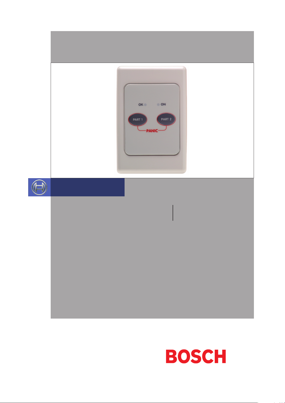
CP050B
Night Arm Station
Security Systems
EN
Installer Reference Guide
Security System
Page 2
CM050B
Installer Reference Guide
CP050B - Night Arm Station
The CP050B Night Arm Station allows you to arm and disarm the system in either PART Mode 1 or PART Mode 2
by simply pressing a single button. Arming in PART Mode automatically disables all zones that you do not wish to
detect intrusion (e.g. Bedrooms, living rooms etc).
PART Mode is ideally used at night when you want only the perimeter of the premises to be in a ready state to
detect intrusion and at the same time allow you to move freely within an area without causing an alarm condition.
Zones that are to be disabled in PART Mode 1 are programmed by the installer and zones which are to be disabled
in PART Mode 2 are programmed by the master user.
CP050B Compatibility
Panel Type Supported
Solution 16i Yes
Solution 16+ No
Solution 64 No
Solution 144 Yes
If an emergency situation arises, the Night Arm Station will allow you to initiate an audible panic alarm. To trigger
a panic alarm, both the PART 1 and PART 2 buttons need to be held down simultaneously for at least two seconds.
The system sirens and strobes will activate and can only be deactivated by entering a valid user code via the keypad.
A panic alarm can be activated at any time whether or not the system is already armed.
Operation
Arming and Disarming in PART Mode 1 and 2
With the system in the disarmed state (OK indicator illuminated or flashing), press the PART 1 button on the Night
Arm Station once to arm the system in PART Mode 1 (ON indicator illuminated). To turn PART Mode 1 OFF, press the
PART 1 button again and the system will disarm.
If the entry warning timer is running or an alarm condition occurs while the system was in either PART mode, you
will not be able to disarm the system using the Night Arm Station. You will need to enter a valid user code at the
keypad.
To arm in PART Mode 2, follow the same procedure as above however press the PART 2 Mode button.
2
Bosch Security Systems 10/12 CP050B FTR1.1
Page 3
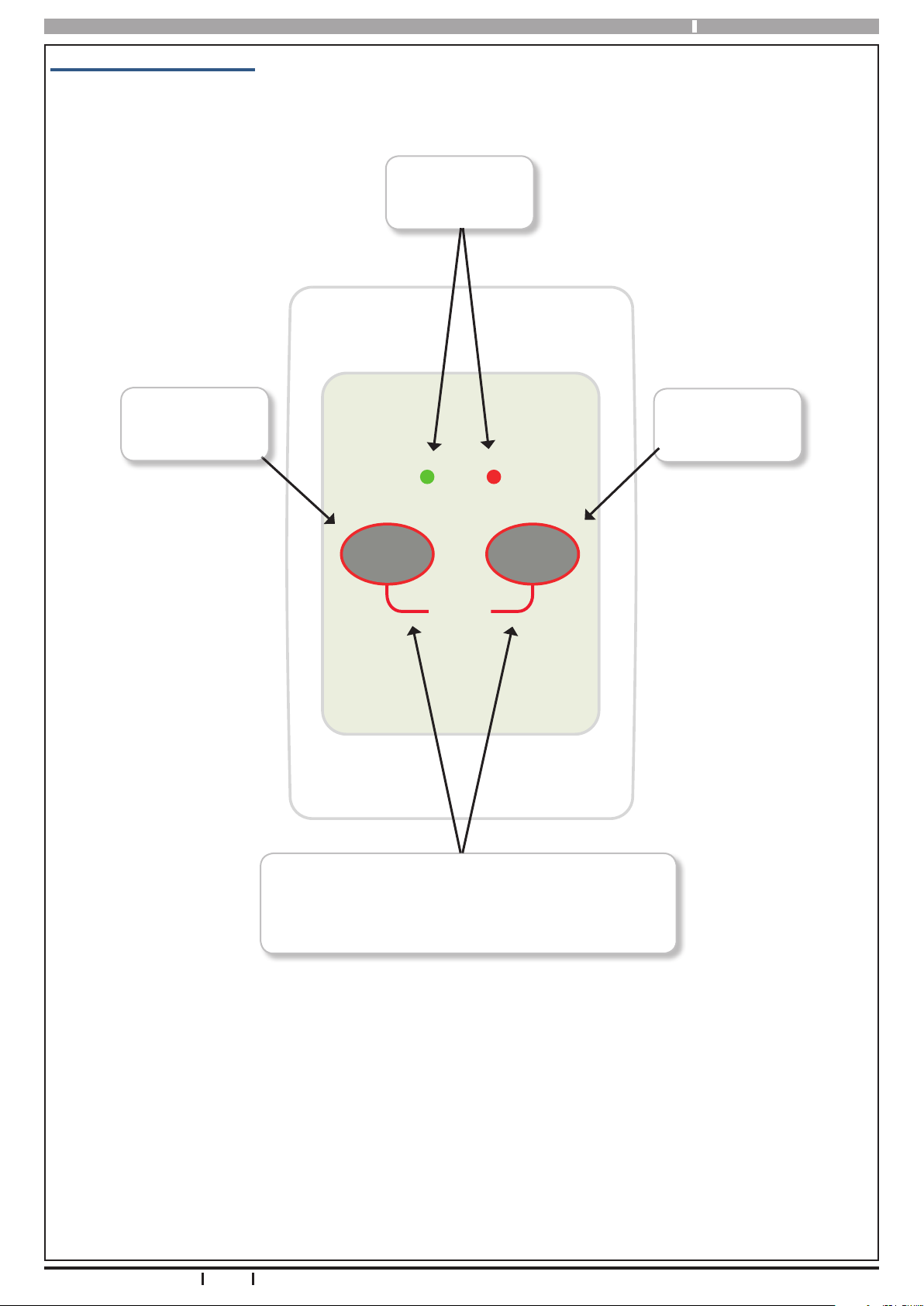
CP050B Front Panel Layout
CM050B Installer Reference Guide
Status
Indicators
Press Button
to Arm or Disarm
Part Mode 1
Press Button
to Arm or Disarm
Part Mode 2
ONOK
PART 1 PART 2
PANIC
Press both buttons together for 2 seconds
Once an alarm has been triggered you will need to
enter a valid code from a keypad to cancel the alarm.
Figure 1: CP050B Buttons and Indicators
Bosch Security Systems 10/12 CP050B FTR1.1
to trigger a Panic Alarm.
3
Page 4
CM050B
i
Note
Triggering a Panic Alarm
To trigger a panic alarm, hold both the PART 1 and PART 2 buttons down for two seconds. This will cause the sirens
and strobe lights to activate and the internal Night Arm Station siren to sound. To reset the system you will need to
enter a valid user code at the keypad. Once the user code is entered, the system will disarm and revert to its normal
state. A panic alarm can be triggered at any time regardless of whether the system is armed or disarmed.
Alarm Status Indication
The Night Arm Station incorporates two indicators which show the status of the system. Should the Night Arm Station fail to display the system status at any time, it may mean that your installer has programmed your system for
keypad extinguish mode. This mode will automatically turn the indicators off sixty seconds after the last key press
on the Night Arm Station, allowing people to sleep in the same room as the Night Arm Station without being disturbed by the indicators. The indicators will re-appear as soon as a key is pressed on any keypad or if an alarm event
occurs. Table :1 provides a list of the indications that may be displayed on the status indicators.
Indicator Brightness
The indicator brightness can be adjusted to suit the environment or personal preference. To adjust, press and hold
down the PART 1 button for 2 seconds. Both the indicators will come on indicating that the change mode is active.
Now press the PART 1 key repeatedly to reduce the brightness or the PART 2 key repeatedly to increase the brightness. Once the desired level has been reached, press and hold down the PART 1 button for 2 seconds to exit.
Installer Reference Guide
You cannot disarm the system from PART mode
if an alarm has occurred or entry warning is
active. You will need to enter a valid user code
at the main keypad to cancel the alarm.
Beeper Tone Change
The buzzer volume can be adjusted to suit the environment or personal preference. To adjust, press and hold down
the PART 2 button for 2 seconds. Once the change mode is active, press the PART 1 key repeatedly to reduce the
volume or the PART 2 key repeatedly to increase the volume until the desired level has been reached, then press
and hold down the PART 2 button for 2 seconds to exit.
CP050B Status Indicators
ON Indicator OK Indicator Keypad Siren System Status Status
OFF OFF OFF Power Fault or Keypad Extinguish Mode
OFF ON OFF System Disarmed, All Zones Sealed
OFF FLASHING OFF System Disarmed, Zone (s) Not Sealed
ON OFF OFF System Fully Armed
ON OFF ON System Fully Armed With Alarm
Table 1: CP050B Status Indicators
4
Bosch Security Systems 10/12 CP050B FTR1.1
Page 5
CM050B Installer Reference Guide
i
Note
Installation Overview
The CP050B module is LAN based, and is designed to be remotely located from the main panel and connected via
the 4 wire RS485 system LAN. As with all LAN devices each CP050B connected to the system must be assigned a
unique address using the on-board dip switches.
The CP050B is seen by the system as if it were a keypad device for the purpose of addressing. This means that the
address selected for each Night Arm Station will consume or occupy the corresponding Keypad address. No Keypad
or Night Arm Station can be set to the same address.
For example, if a system is to have 1 x Keypad and 1 x Night Arming Station then the address for the Keypad should
be set to 1 and the address for the Night Arm Station should be set to address 2. If at a later stage a second keypad
was added, then it would be set to address 3.
See the Table: 2 for a list of valid module addresses and the corresponding mappings for each module.
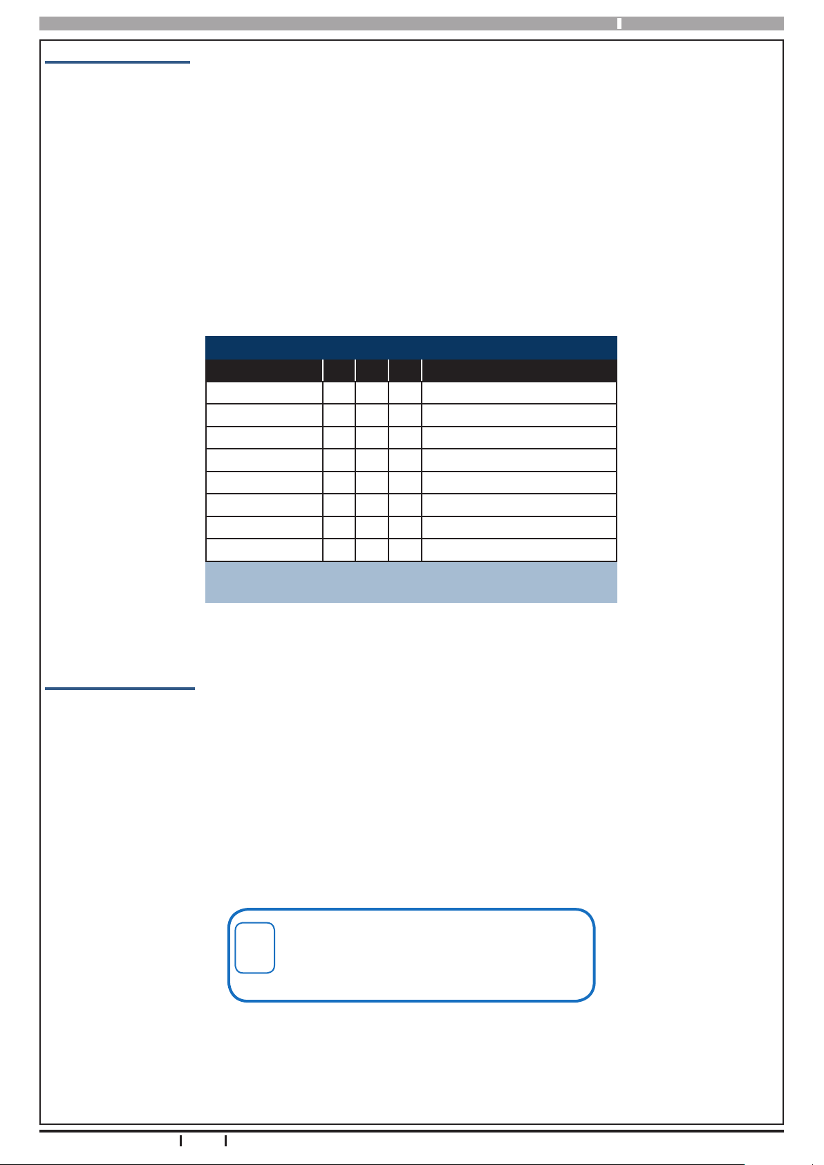
Address Configuration
Switch Number SW1 SW2 SW3 Night Arm Station Number
Address 1 = OFF OFF OFF 1
Address 2 = ON OFF OFF 2
Address 3 = OFF ON OFF 3
Address 4 = ON ON OFF 4
Address 5 = OFF OFF ON 5
Address 6 = ON OFF ON 6
Address 7 = OFF ON ON 7
Address 8 = ON ON ON 8
Up to 8 x CP050B can be installed on the
Solution 16i and Solution 144 panels.
Table 2: CP050B Address Configuration Settings
Installation Procedure
1) Mount the CP050B in the desired location. If required, the unit can be mounted on a standard GPO
mounting block.
2) Set the appropriate address for the CP050B via the dip switches.
3) Make sure the LAN is in unsecured mode and the remove power from the control panel.
4) Connect the 4 wire LAN from the CP050B to the control panel, and then reconnect power to the system.
5) During power up the panel will scan the LAN for new devices and the CP050 will be registered onto the
system.
6) If required, re-secure the LAN.
You must power cycle the panel after connecting
the CP050B for the system to initialise the Night
Arm Station. The LAN must be in unsecured
mode.
Bosch Security Systems 10/12 CP050B FTR1.1
5
Page 6
CM050B
i
Note
Programming
Each CP050B is treated by the panel as if it were a standard keypad from the point of view of programming options.
This means that to change parameters for a Night Arm Station which is configured for address 3 you would need to
select Keypad 3 under the devices menu and change the required parameters..
In a multi-area system you need to set the appropriate Home Area for the Night Arm Station to control. Each Night
Arm Station can only control part arming for its home area.
Program any zones which are required to be isolated when armed in Part mode 1 and or Part Mode 2 before testing
the system operation. As a general rule Part Mode 1 zones are programmed by the installer and Part Mode 2 zones
can be programmed by the user.
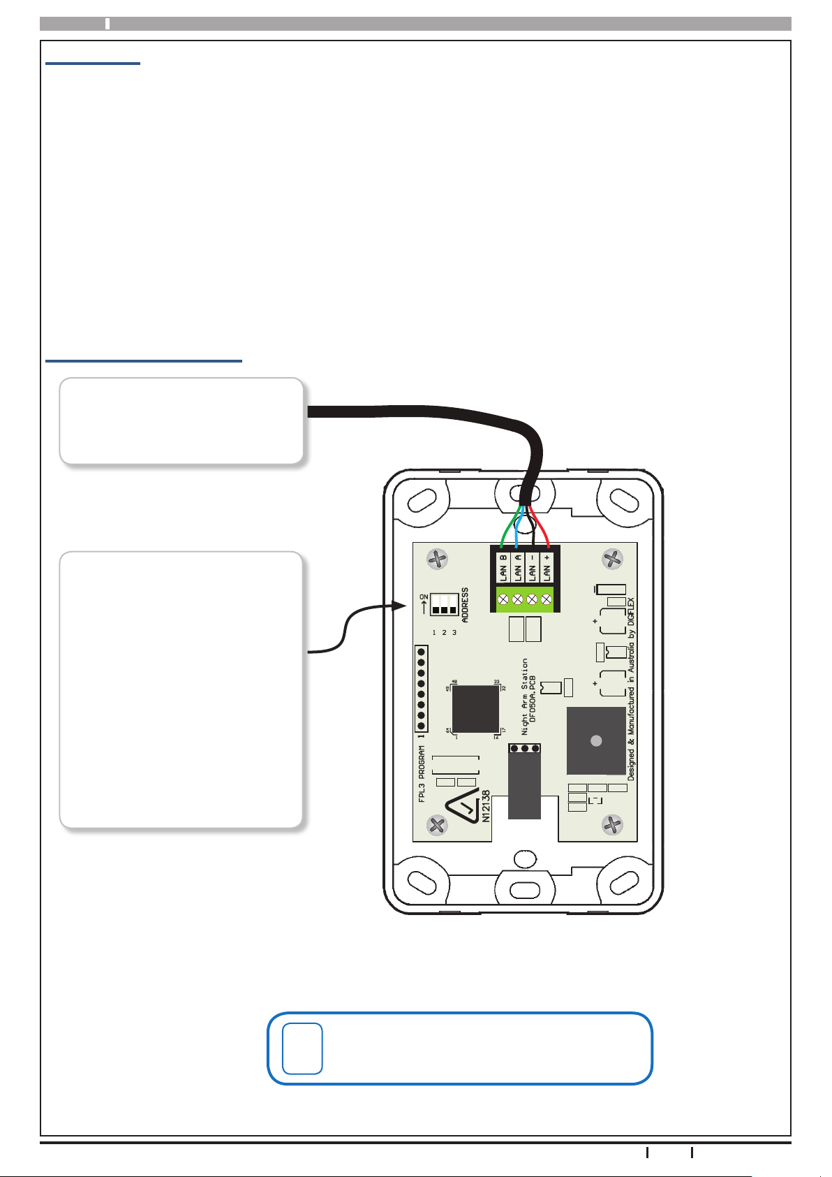
CP050B Connection Diagram
Connect to 4 wire RS485 system
LAN. See module connection
specification below for more
detail.
Installer Reference Guide
Night Arm Station Address
Select Switch. Each CP050B fitted to the system must be set to
a unique address via this switch.
See Table 2.
It is important to remember that
each Night Arm Station added
consumes the corresponding
keypad address.
This means that if you have a
keypad set to address 2 then you
cannot also set a Night Arm
Station to address 2.
Figure 2: CP050B Connection Diagram
The CP050B Night Arm Station is not compatible
with Solution 64 or Solution 16plus panels.
Contact your distributor for more information.
6
Bosch Security Systems 10/12 CP050B FTR1.1
Page 7

CM050B Installer Reference Guide
CP050B Specifications
Part Number: CP050B - Night Arm Station
Operating Voltage:
Module Connection:
(RS485 LAN)
Operating Environment: 0˚ to 55˚C RH 5 to 85% at 30˚C non-condensing.
Fixing Method:
Warranty: 3 years from date of manufacture (return to base)
N12138N12138
Bosch Security Systems 10/12 CP050B FTR1.1
10.5V D.C - 14.0V D.C. @ 20mA Stand-by, Max 50mA
(All LED’s and Buzzer Operating)
Max total LAN length using multi strand security cable = 300m ,
Max total LAN length using 2 pair twisted shielded data cable (Belden 8723) = 1200m.
See the control panel manual for full wiring instructions.
The CP050B can be directly installed onto a cavity or plaster wall using appropriate fixings or onto a solid
masonry or brick wall using a standard height GPO mounting block (Clipsal or Similar).
RoHS
In the interest of ongoing product development this
document is subject to change without notice.
7
Page 8

Bosch Security Systems
25 Huntingwood Drive
Huntingwood, NSW 2148
Australia
Phone: +612 9672 1777
Facsimile: +612 9672 1717
© 2012 Bosch Security Systems
CM050BIRG
Issue FTR1.1
 Loading...