

Page 1
CM744B
3G GSM/GPRS/SMS Radio Module
Security Systems
EN
Installer Reference Guide
Security System
Page 2
CM744B
Installer Reference Guide
Introduction
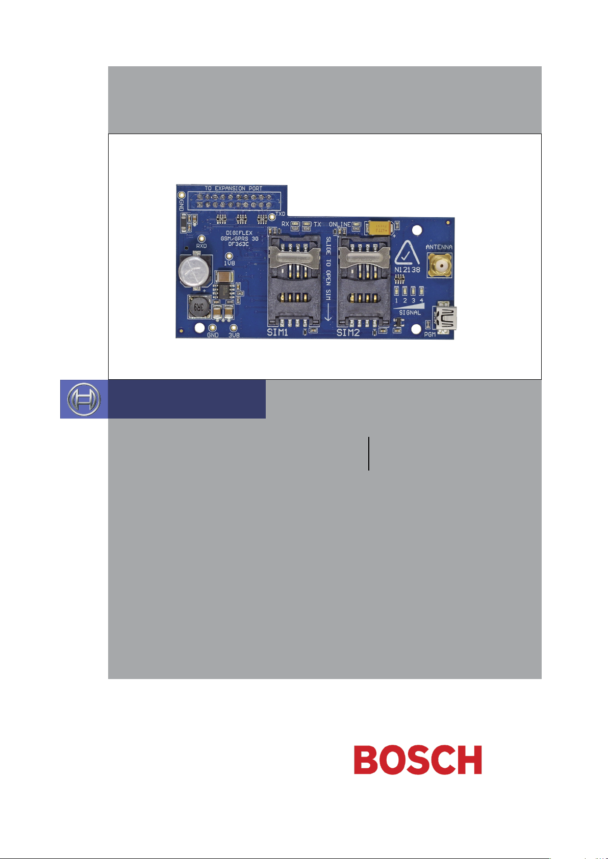
The CM744B 3G radio module allows you to interface
compatible security control panels to the GSM/GPRS /SMS
network providing a high reliability primary or backup
reporting path.
The unit is designed to plug onto the main control panel
with the supplied antenna mounting onto the metal
cabinet.
Module Compatibility
Panels Supported Version
Solution 6000 Series 2.23
Getting Started
There are four main steps required to configure the
CM744B for reporting to the control room. The instructions assume that you already have purchased a SIM card
and that the card has been charged with credit and activated on the network if necessary.
Step 2 - Installing the Antenna
Remove the knockout in the top of the cabinet and pass
the antenna lead through the hole ensuring the antenna
is on the outside of the cabinet. Screw the lead to the
socket on the radio module before power the panel.
Do not fix the antenna in place at this stage.
Step 3 - Configuring The Module
Once powered the radio will attempt to connect to the
network. This may take up to a minute to complete. During this time the online indicator on the module will be on
solid. Once the radio has registered the online indicator
will begin to flash and the signal strength indicators will
show the current signal condition.
Experiment with the position of the antenna to find the
best signal strength before fixing it in place.
1. Install the CM744B hardware on the control panel.
2. Install the antenna.
3. Configure the module’s features and parameters.
4. Configure the control panel for reporting.
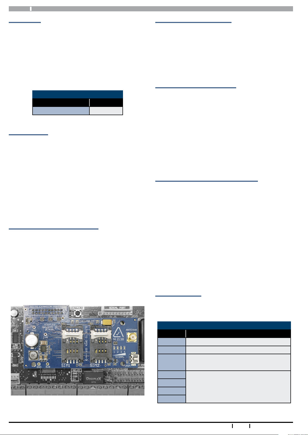
Step 1 - Installing the Radio Module
Ensure that the panel is powered off before proceeding.
Plug the 3 short plastic standoffs into the module and
then plug it onto the Expansion Port header pins on the
panel as shown in. If you are connecting the CM744B to a
panel which also has a CM101B Voice Module fitted then
you should use the longer standoffs from the HW750 Riser
Kit.
Install the SIM card into the SIM 1 card position.
Step 4 - Configuring The Panel Reporting
Reporting configuration will vary depending on the required options and whether or not the GSM module is to
be used as the primary or secondary reporting route.
Configure the required reporting formats in MENU 5-4-0
and 5-4-1. The system can be configured to report to the
base in CID and also to selected phone numbers via SMS,
or to the base in CID via PSTN line and then CID via GSM if
the PSTN line is cut.
All reporting scenarios are configured by varying the programming of the reporting format and reporting routes
configurations options.
Module Indicators
The module includes 7 led indicators which are used to
show status and signal strength. See table below.
Module Indicators
Indicator Meaning
TX Module Transmitting Data
RX Module Receiving Data
Online
Signal 1
Signal 2
Signal 3
Signal 4
2
ON Steady = Not Registered On Network
Pulsing = Registered On Network
Signal strength indicators show relative
signal level at the radio. Signal indicator 1
on indicates weak signal and all 4 indicators
on indicates stronger signal strength.
Bosch Security Systems 07/15 CM744BIRG FTR1.1
Page 3
CM744B Installer Reference Guide
Supported Reporting Formats
Version 2.22 of the Solution 6000 panel firmware is
required to support the CM744B.
The following reporting formats are currently supported
by the module.
SMS Format via GSM
CSV-IP Format via GPRS
Conettix Format via GPRS
Support for the MyAlarm iFob App and RAS upload /
download via GPRS is not currently supported but will be
available in a future panel firmware update.
There is no support in the 3G module for Contact ID (CID)
over GSM.
CLI Trigger Output Control
The CLI trigger tables in MENU 6-5-5-1 and 6-5-6-2 can be
used to store a list of telephone numbers that can trigger
an output on the control panel. If you call the GSM unit
from a telephone number that matches a number in the
CLI list then the appropriate output will be operated.
An output needs to be programmed with an event type of
CLI Trigger and event assignment of 1 or 2 depending on
which table is to be checked.
SMS Remote Control
The SMS control option in MENU 6-5-6 allows you to
program up to 10 telephone numbers that are allowed
to send SMS commands to the GSM unit. The first number in this list is considered as the administrator who will
also receive SMS messages that the GSM unit is unable to
interpret. i.e. any message sent to the radio which cannot
be interpreted will be sent back via SMS to the first number in the SMS control number list.
Numerous commands can be sent to the panel using the
SMS control functions including arming/ disarming areas,
controlling outputs and doors or checking system status.
The panel can also be requested to send a confirmation
SMS if required.
The control messages must be sent to the SIM phone
number.
The SMS Control phrase table shows the correct method
for constructing the SMS messages. Note there are no
spaces between the fields only commas as shown.
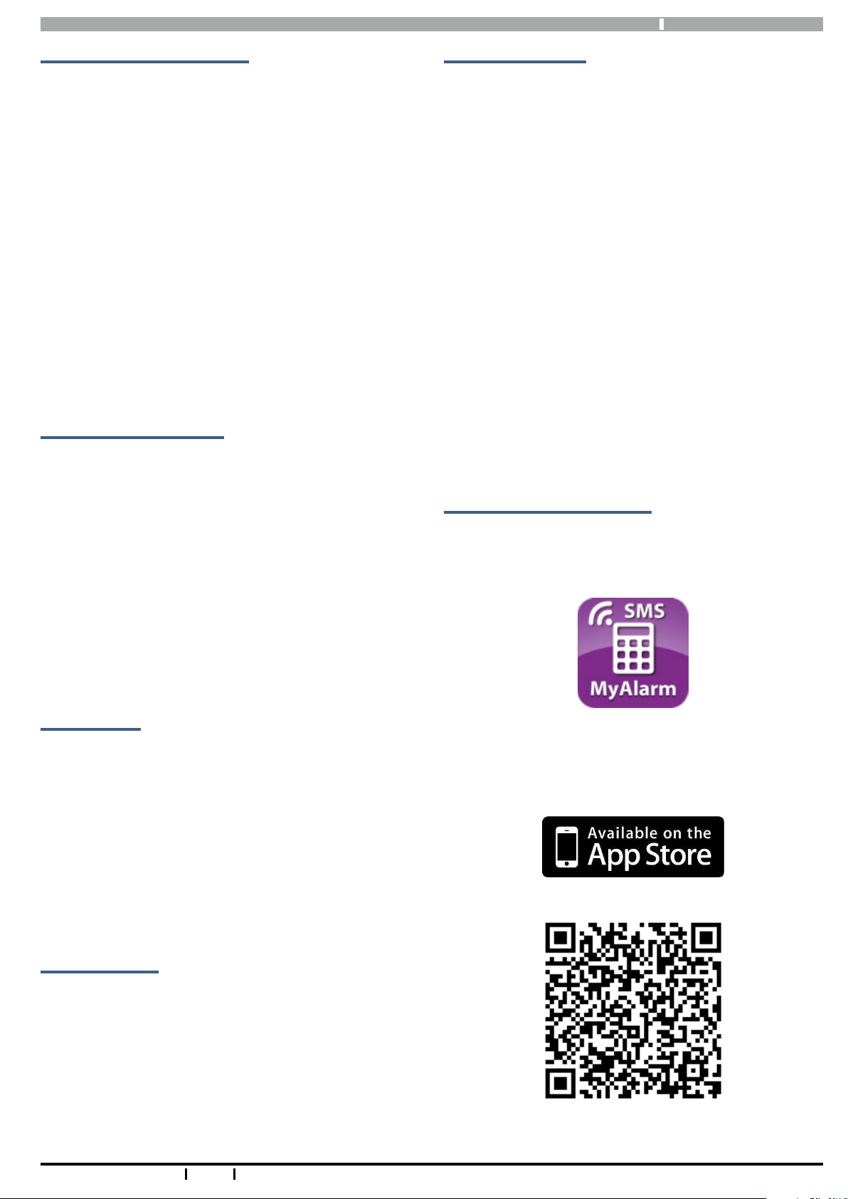
SMS Control Smartphone App
The MyAlarm SMS Control App for iOS and Android
devices is now available and can be used to simplify the
configuration and sending of SMS control messages.
Simply call the GSM unit from a telephone number that is
programmed in the CLI trigger list to activate the output.
Module Status
MENU 6-5-0 can be used to obtain various information on
the radio module. The following information is currently
available.
1) Connected Network
2) Signal Strength in dB
3) IMEI Number
4) Radio Firmware Revision
5) SIM Card Present
Dial Number Test
It is possible to check the SIM phone number by selecting
the dial number test via GSM option in MENU 5-9-5.
You can search for the MyAlarm SMS Control app in the
app store or scan the QR codes below using your device’s
barcode reader for a direct link to the app.
Bosch Security Systems 07/15 CM744BIRG FTR1.1
Scan Here (iOS Version)
3
Page 4

CM744B
Installer Reference Guide
Scan Here (Android Version)
SIM Balance Recharge Reminder Function
In Solution 6000 version 2.20 firmware, a new SIM expire parameter can be added to the to the SIMBAL setup
command when using the GSM module with a pre-paid
SIM card. When configured the control panel will send a
reminder to the designated SIM owner prompting them
to recharge the SIM before it expires.
Text
Enter the text required by the communication providers
to obtain your SIM card balance (Max = 16 characters). In
Australia, examples may change and include:
• Optus = Balance
• Vodafone = Blank Message
• Telstra = Voice Call
• Virgin = Bal
Preamble
Enter text to search for the credit remaining on your SIM
card (eg. if Vodafone Australia displays ‘U’ve Remaining:
365 day: $35.53 Exp: 09/11/2015’ enter ‘Day:’ as the preamble).
Minimum Amount
Enter the minimum balance to filter GSM module SIM card
balance enquiries. This allows the GSM module to only
forward an SMS balance alert message to your mobile
telephone when the SIM card balance falls below the
minimum amount set here.
Days
This parameter sets how often the GSM module will
automatically request a SIM card balance. This can be set
between 001 and 255 days / 000 = disabled.
Mobile
The SIM Balance string would include the follows parameters including the new optional reminder in weeks (01 to
52 weeks).
The MyAlarm SMS Control smart device app has been
updated to include support for this new feature. For more
information refer to the example below.
User Code
This field is used to enter your PIN (eg. 2580).
Command Header
The command header field is fixed - SIMBAL.
Access Number
Enter the communication providers access number for
SIM card balance enquiries.
• Optus = 9999
• Vodafone = 1555 / 1512
• Telstra = #100#
• Virgin = 225
This parameter allows you to program which mobile
telephone number the GSM module will forward the SIM
card balance enquiry of the GSM module to.
Expire Reminder
Enter the number of weeks for the GSM module to remind
you to recharge your GSM SIM card (01 to 99 weeks / 00 =
disabled).
Example
The example below is requesting a SIM Balance of the SIM
card connected to the Vodafone network (Australia) with a
reminder that the credit available on the SIM card requires
a recharge in 25 weeks using a 180 day prepaid SIM card.
The SIMBAL requests a balance enquiry every two days
when the balance falls below $20.00.
SIMBAL,2580,1555,Day,$20.00,002,0414123456,25
After 25 weeks, the GSM module will send the following
SMS, ‘SIM is about to expire please recharge immediately’.
Information in this example is correct at time of printing. Check with your telco carrier as these options may
change.
4
Bosch Security Systems 07/15 CM744BIRG FTR1.1
Page 5

CM744B Installer Reference Guide
Description SMS String
Arming / Disarming Areas
Turning Area 1 On <User Code>,AREA,1,ON
Turning Area 1 On With Confirmation <User Code>,AREA,1,ON,CONFIRM
Turning Area 1 Part 1 On <User Code>,AREA,1,PART 1
Turning Area 1 Part 1 On With Confirmation <User Code>,AREA,1,PART 1,CONFIRM
Turning Area 1 Part 2 On <User Code>,AREA,1,PART 2
Turning Area 1 Part 2 On With Confirmation <User Code>,AREA,1,PART 2,CONFIRM
Turn Multiple Areas On <User Code>,AREA,1,2,3,4,ON
Turn All Areas On That the User Belongs To <User Code>,AREA,ON
Turning Area 1 OFF <User Code>,AREA,1,OFF
Turning Area 1 OFF With Confirmation <User Code>,AREA,1,OFF,CONFIRM
Check Area Status <User Code>,AREA,1,STATUS
Check Status Of Multiple Areas <User Code>,AREA,1,2,3,STATUS
Turning Outputs On/Off
Turn Output 1 On <User Code>,OUTPUT,1,ON
Turn Output 1 On With Confirmation <User Code>,OUTPUT,1,ON,CONFIRM
Turn Multiple Outputs On <User Code>,OUTPUT,1,2,3,4,ON
Turn Multiple Outputs On With Confirmation <User Code>,OUTPUT,1,2,3,4,ON,CONFIRM
Turning Output 1 OFF <User Code>,OUTPUT,1,OFF
Turning Output 1 OFF With Confirmation <User Code>,OUTPUT,1,OFF,CONFIRM
Turning Multiple Outputs OFF <User Code>,OUTPUT,1,2,3,4,OFF
Turning Multiple Outputs OFF With Confirmation <User Code>,OUTPUT,1,2,3,4,OFF,CONFIRM
Check Output Status <User Code>,OUTPUT,1,STATUS
Check Status Of Multiple Outputs <User Code>,OUTPUT,1,2,3,4,STATUS
Locking and Unlocking Doors
Unlock Door 1 <User Code>,DOOR,1,UNLOCK
Unlock Door 1 With Confirmation <User Code>,DOOR,1,UNLOCK,CONFIRM
Unlock Multiple Doors <User Code>,DOOR,1,2,3,UNLOCK
Unlock Multiple Doors With Confirmation <User Code>,DOOR,1,2,3,UNLOCK,CONFIRM
Lock Door 1 <User Code>,DOOR,1,LOCK
Lock Door 1 With Confirmation <User Code>,DOOR,1,LOCK,CONFIRM
Lock Multiple Doors <User Code>,DOOR,1,2,3,LOCK
Lock Multiple Doors With Confirmation <User Code>,DOOR,1,2,3,LOCK,CONFIRM
Check Status Of A Door <User Code>,DOOR,1,STATUS
Check Status Of Multiple Doors <User Code>,DOOR,1,2,3,STATUS
Check System Status <User Code>,SYSTEM,STATUS
SIM Balance Check - Must have been configured under site settings
Check Current SIM Balance <User Code>,SIMBAL,<Access Number>,<Text.,
<Preamble>,<Min Amount>,<Days>,<Mobile>,<Expire
Reminder>
Bosch Security Systems 07/15 CM744BIRG FTR1.1
5
Page 6

CM744B
Installer Reference Guide
Page Intentionally Blank
6
Bosch Security Systems 07/15 CM744BIRG FTR1.1
Page 7

CM744B Installer Reference Guide
CM744B Specifications
Part Number: CM744B - 3G GSM/GPRS/SMS Radio Module
SMS via GSM , CSV-IP via GPRS and Conettix Format via GPRS are supported.
Reporting Formats:
SIM Card Type:
Antenna: Quad Band Omni Directional Adhesive Antenna with integrated lead and SMA Connector. 3dbi gain - 50 ohm
Operating Environment: 0˚ to 55˚C RH 5 to 85% at 30˚C non-condensing.
Fixing Method:
Warranty: 3 years from date of manufacture (return to base)
Bosch Security Systems 07/15 CM744BIRG FTR1.1
iFob app and RAS will be available via a future panel firmware update. Check with your distributor for availability.
The CM744B does not support Contact ID (CID) over GSM.
Dual standard size SIM cards.
When using the module in single SIM mode the SIM card should be installed in SIM 1 socket.
The CM744B is mounted directly to the expansion port on the control panel PCB. Three plastic standoffs are supplied to support the module and these should be connected to the control panel before installing the CM744B.
In the interest of ongoing product development this
document is subject to change without notice.
7
Page 8

Bosch Security Systems
Level 2, 21 Solent Circuit
Baulkham Hills, NSW 2153
Australia
Phone: +61(2) 9842 4743
Facsimile: +61(2) 8850 2230
© 2015 Bosch Security Systems
CM744BIRG
Issue FTR1.1
 Loading...