

Page 1
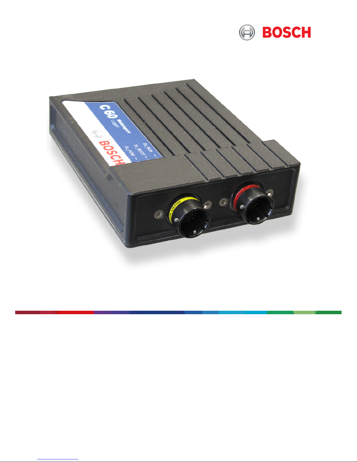
Data Logger C60
Manual
Version 1.0 12/03/2019
Page 2

Content
ii/108 Data Logger C 60 Bosch Motorsport
Content
1 Onboard Network Concept............................................................................................................................................ 4
2 Preparation...................................................................................................................................................................... 5
3 Power Supply .................................................................................................................................................................. 6
4 Error Memory .................................................................................................................................................................. 7
4.1 Error memory representation in RaceCon .................................................................................................................................................. 7
4.2 Information on errors available from the error memory ...................................................................................................................... 9
4.3 Analog Input Diagnosis...................................................................................................................................................................................... 13
5 Technical Data................................................................................................................................................................. 15
6 Disposal............................................................................................................................................................................ 20
7 Mechanical Drawing ....................................................................................................................................................... 21
8 Starting up the C 60........................................................................................................................................................ 22
8.1 Before starting ....................................................................................................................................................................................................... 22
8.2 Feature activation................................................................................................................................................................................................. 25
8.3 First recording (Quick start).............................................................................................................................................................................. 25
8.4 Status LEDs.............................................................................................................................................................................................................. 26
8.5 Set Time & Date.................................................................................................................................................................................................... 27
9 CAN Bus ........................................................................................................................................................................... 28
9.1 CAN bus trivia ........................................................................................................................................................................................................ 28
9.2 CAN input................................................................................................................................................................................................................ 28
9.3 CAN output............................................................................................................................................................................................................. 33
10 Analog and Frequency Inputs ....................................................................................................................................... 36
10.1 Features.................................................................................................................................................................................................................... 36
10.2 Analog inputs......................................................................................................................................................................................................... 36
10.3 Configuring inputs ............................................................................................................................................................................................... 37
10.4 Computed sources............................................................................................................................................................................................... 48
10.5 Hysteresis................................................................................................................................................................................................................. 49
10.6 Configuring PWM outputs................................................................................................................................................................................ 52
10.7 Analog inputs......................................................................................................................................................................................................... 55
10.8 Configuring inputs ............................................................................................................................................................................................... 55
10.9 Computed sources............................................................................................................................................................................................... 64
10.10 Hysteresis................................................................................................................................................................................................................. 65
10.11 Configuring PWM outputs................................................................................................................................................................................ 67
11 Online Measurement ...................................................................................................................................................... 70
11.1 Achieving an online connection ..................................................................................................................................................................... 70
11.2 Setting up an online measurement............................................................................................................................................................... 71
11.3 Online calibration of measurement channels............................................................................................................................................ 73
11.4 Group adjustment ................................................................................................................................................................................................ 75
11.5 Online calibration of multipoint adjustment channels .......................................................................................................................... 77
12 Recording and Telemetry............................................................................................................................................... 79
12.1 Features.................................................................................................................................................................................................................... 79
12.2 Configuration of recordings............................................................................................................................................................................. 79
12.3 Configuration of online telemetry ................................................................................................................................................................. 83
12.4 Configuration of burst telemetry ................................................................................................................................................................... 85
Page 3

Content
Bosch Motorsport Data Logger C 60 iii/108
12.5 Setup for USB recording.................................................................................................................................................................................... 85
13 Lap Trigger ...................................................................................................................................................................... 89
13.1 Lap trigger (timing beacon).............................................................................................................................................................................. 89
13.2 Counting outing/laps/fragments ................................................................................................................................................................... 92
13.3 Lap timing................................................................................................................................................................................................................ 93
14 Firmware .......................................................................................................................................................................... 97
14.1 Firmware and configuration............................................................................................................................................................................. 97
14.2 Firmware update................................................................................................................................................................................................... 97
15 Clone the Unit ................................................................................................................................................................. 99
16 Fuel Consumption Calculation ...................................................................................................................................... 100
16.1 Setting up fuel consumption calculation and tank management..................................................................................................... 100
16.2 Fuel consumption diagnosis/counter reset................................................................................................................................................ 100
16.3 Example .................................................................................................................................................................................................................... 101
17 GPS Sensor....................................................................................................................................................................... 102
17.1 GPS (Global Positioning System).................................................................................................................................................................... 102
17.2 Protocol.................................................................................................................................................................................................................... 102
17.3 Sensor recommendation ................................................................................................................................................................................... 102
17.4 Measurement labels ............................................................................................................................................................................................ 102
17.5 GPS troubleshooting........................................................................................................................................................................................... 103
18 RaceCon Shortcuts.......................................................................................................................................................... 105
Page 4
1 | Onboard Network Concept
4/108 Data Logger C 60 Bosch Motorsport
1 Onboard Network Concept
G
Engine_GND
GND_Starpoint
Chassis
KL31
LS_GND_1
LS_GND_2
Main
Switch
UBAT
Star connection
(term30)
positive terminal
Electric Loads
IGN-
Switch
KL15
SENSPWR5
SENSGND
active
Sensor
ANA_IN(xx)
NTC
Sensor
ANA_IN(xy)
switched pos. terminal
Star connection
dig. sensors
(e.g. wheelspeed)
µC
As short as
possible
SENSPWR10
UBATT_FUSE
KL30
LS_SWITCH1…4
Bosch Motorsport
diagnosis connector
PC
Device
NOTICE
This schematic is not device specific, please see the section “Technical Data for the specifications of your device.
Page 5
Preparation | 2
Bosch Motorsport Data Logger C 60 5/108
2 Preparation
Use the C 60 only as intended in this manual. Any maintenance or repair must be performed by authorized and qualified personnel approved by Bosch Motorsport.
Operation of the C 60 is only certified with the combinations and accessories that are specified in this manual. The use of variant combinations, accessories, and other devices outside the scope of this manual are only permitted when they have been determined to be
compliant from a performance and safety standpoint by a representative from Bosch
Motorsport.
Read the manual carefully and follow the application hints step by step. Do not hesitate to
contact us, contact data can be found on the last page of this document.
Disclaimer
Due to continuous enhancements, we reserve the rights to change any illustrations, photos and technical data within this manual.
Please retain this manual for your records.
NOTICE
In this document, all screenshots are created by way of example for a
display. Please consider this and replace the product names with the
name of your device.
Page 6

3 | Power Supply
6/108 Data Logger C 60 Bosch Motorsport
3 Power Supply
Please ensure that you have a good ground installation. That means:
– A ground that has a solid, low resistance connection to the negative battery terminal
– Connection should be free from dirt, grease, paint, anodizing, etc.
– Use large diameter wire
– More metal-to-metal contact is better!
The following notations for power signals are used:
– KL 15 is a switched battery rail controlled by the IGN-switch
– KL 30 is an unswitched battery positive rail (same as battery positive terminal)
– KL 31 is an unswitched ground rail (same as battery negative terminal)
Be careful to observe current limits of wires and connector pins!
Page 7
Error Memory | 4
Bosch Motorsport Data Logger C 60 7/108
4 Error Memory
In this chapter “Error Memory”, a lot of screenshots are created by way of example for
DDU 8. Please consider this and replace the product name ‘DDU 8’ in this case with the
name of your product.
4.1 Error memory representation in RaceCon
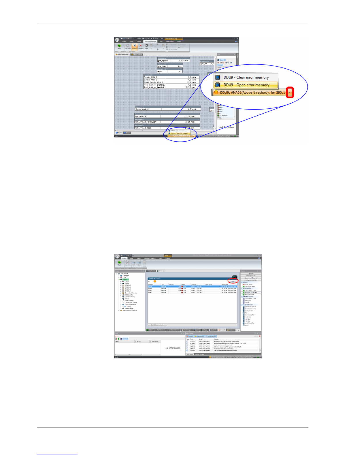
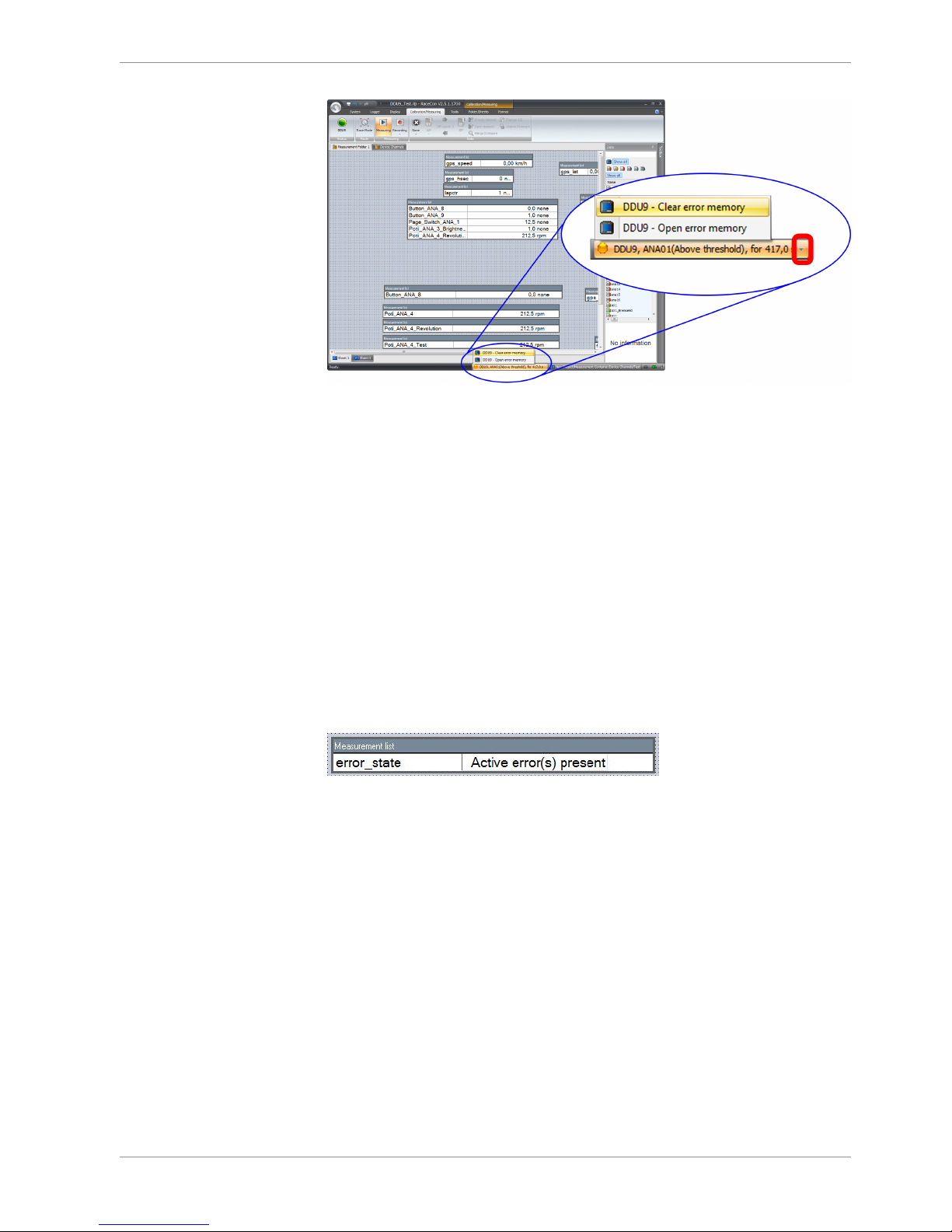
Bosch Motorsport devices feature an error memory. Information on errors can be visualized via RaceCon (online measurement) or can be transmitted via telemetry.
4.1.1 Accessing the memory
The error memory can be accessed as shown in the illustration:
Page 8
4 | Error Memory
8/108 Data Logger C 60 Bosch Motorsport
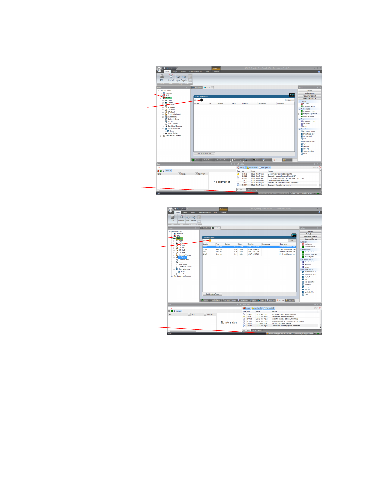
The memory is situated inside the device and is non‐volatile. As a consequence, an error
which has occurred and has not been cleared by the user will remain in the error memory
even after a power cycle. The error state will then reflect if the error is still active or not.
An error is deleted from the list when
– the user actively clears the error memory
– the user updates the firmware
The error memory is not cleared by a configuration download and is not cleared by a
power cycle.
4.1.2 Clearing the error memory
There are two ways of clearing the error memory, both are shown in the following illustration:
Page 9
Error Memory | 4
Bosch Motorsport Data Logger C 60 9/108
4.2 Information on errors available from the
error memory
In general, properties of the error memory and properties of an individual error need to
be distinguished.
4.2.1 Error Memory Properties
The following property is available for the error memory itself:
– Error Status (device measurement label “error_state”)
0: no error present in memory
1: at least one inactive error present in memory, no active errors
2: at least one active error present in memory
If displayed in a measurement sheet, this property’s value (0, 1 or 2) is translated into a
verbal description:
Page 10
4 | Error Memory
10/108 Data Logger C 60 Bosch Motorsport
It is also represented by a color scheme within RaceCon (provided RaceCon is online with
the system):
0 (no error present in memory):
No orange border
MIL off (black)
No entries
1 (at least one inactive error present in memory, no active errors):
Constantly orange border
Info cycling through
errors, present in
error memory
MIL constantly orange
Page 11
Error Memory | 4
Bosch Motorsport Data Logger C 60 11/108
2 (at least one active error present in memory):
MIL blinking orange
Blinking orange border
Info cycling through
errors present in
error memory
4.2.2 Error Properties
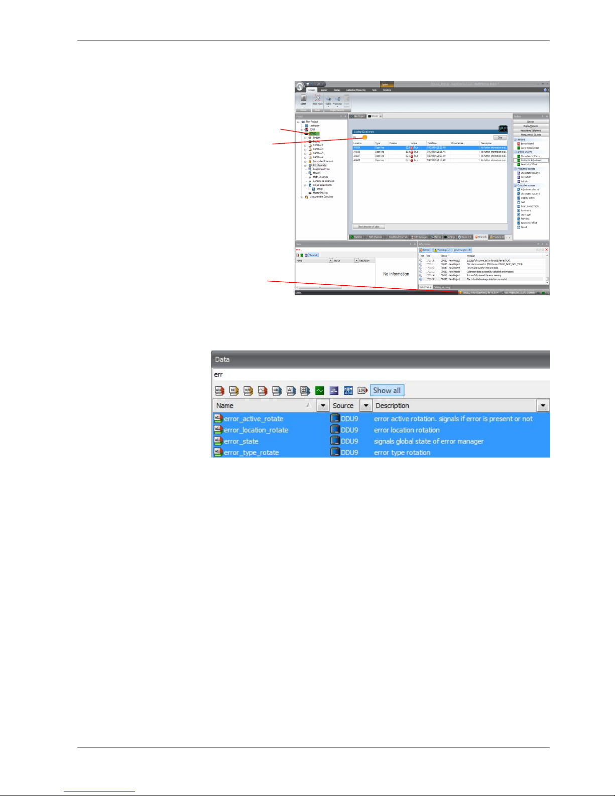
The following channels are recognized and memorized inside the devices:
– Error type (device label “error_type_rotate”):
e.g. “below_threshold” for a violation of the minimum voltage range defined in the
configuration, “shortcut_Batt” for a shortcut to battery voltage etc.
– Error locations (device label “error_location_rotate”):
e.g. “ANA01” for an error concerning the first ANA channel
– Error durations
How long has the error been active? If an error encounters a non-active period before
being cleared from the memory and is then detected again, the error duration keeps
on accumulating. The number of active periods can be seen from the “number of occurrences”.
– Number of occurrences
How many times has the error been detected since the last time the error memory
was cleared.
– Error active state (device label “error_active_rotate”)
All failure modes are continuously diagnosed; any error detected will be written to the
error memory. Once an error is detected, it is qualified as “active”.
– 1 (TRUE) Error was detected in most recent diagnose run (active)
Page 12
4 | Error Memory
12/108 Data Logger C 60 Bosch Motorsport
– 0 (FALSE) Error is inactive: error was not detected in most recent diagnostic run,
however the error has not been cleared from the memory by the user and remains in the non‐volatile memory
The aforementioned channels (error_active_rotate, error_location_rotate, error_type_rotate) are device specific properties (e.g. C 60) and are not related to the complete RaceCon project (e.g. “error no. 3 from the error memory”). Therefore, only one property label
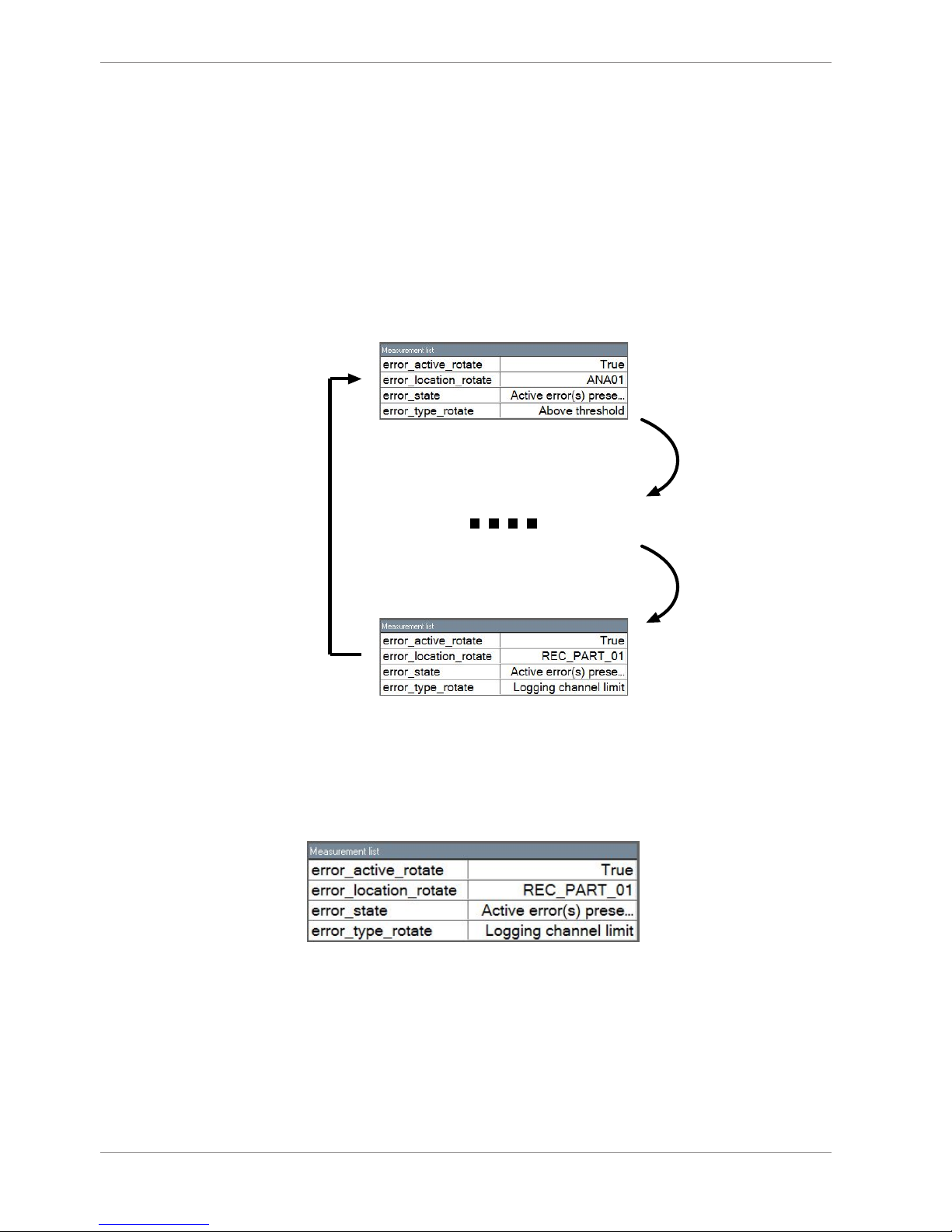
is available in each device. The errors from the error memory (possibly more than one error possible per device) share these three labels. The labels cycle through the errors currently present in the memory and represent the respective property of each error periodically.
The following screenshot shows error properties, which can be displayed or logged:
Labels hold information
on error 1 (an ANA3 error)
Labels hold information
on error 2 ... n-1
Labels hold information
on error n (a CAN error)
After the last error and its error properties have been displayed, the labels will start again
with the first error in the error memory stack and its error properties will be displayed
again. Therefore, monitoring these labels over a sufficiently long period provides the information on all individual errors in the error memory.
To understand this behavior, it is recommended to observe the three labels in a measurement sheet (while more than one error is active) and watch the values change periodically:
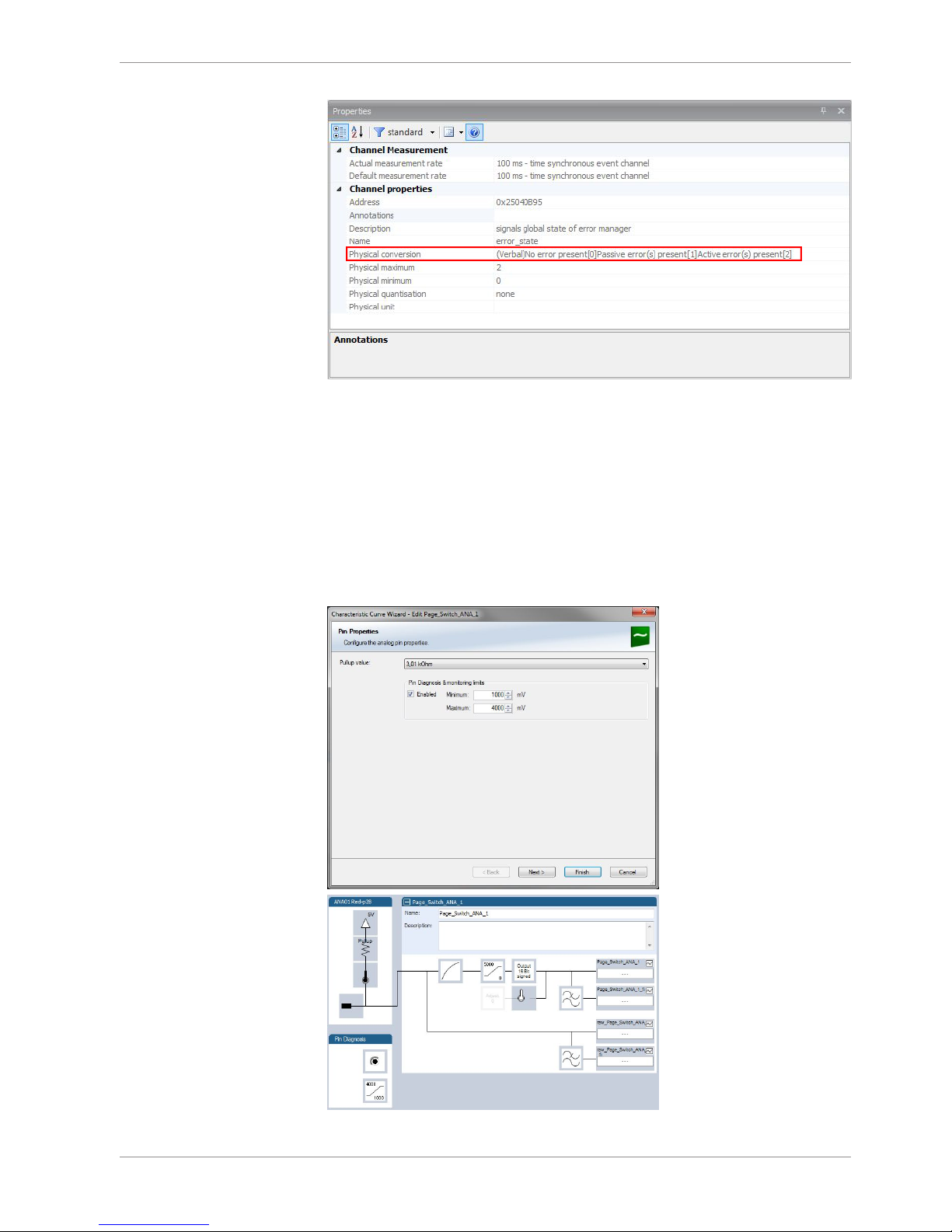
The verbal representation of the numerical codes of these labels can be visualized in the
properties window of the measurement page:
Page 13
Error Memory | 4
Bosch Motorsport Data Logger C 60 13/108
4.3 Analog Input Diagnosis
4.3.1 Monitoring limits / Shortcut Detection / Cable
Breakage
The pin diagnosis functionality (check whether measurement is within the desired range)
can be activated in the ANA pin setup wizard; to allow for a diagnosis regarding shortcut
to ground, shortcut to battery voltage and cable breakage, a minimum / maximum has to
be defined.
Page 14

4 | Error Memory
14/108 Data Logger C 60 Bosch Motorsport
4.3.2 Open Line Detection
The implementation of open line detection consists of pull up resistors being activated
and deactivated; evaluating the behavior of the measured value detects cable breakage,
regardless of the pull up resistor being activated by the user.
1. Open the Error Memory of the Device.
2. Click "start detection of cable".
3. Check the Error Memory for new fault entries, regarding "Open line errors".
Page 15
Technical Data | 5
Bosch Motorsport Data Logger C 60 15/108
5 Technical Data
Application
Technical Specifications
Mechanical Data
Size 105 x 34.5 x 137.5 mm
Weight 495 g
Protection Classification IP67 to DIN 40050, Section 9, Issue 2008
Operating temperature (internal) -20 to 65°C
Max. vibration Vibration profile 1 (see Appendix or
www.bosch-motorsport.com)
Electrical Data
Supply voltage 8 to 18 V
Max. power consumption (w/o loads) 10 W at 14 V
Inputs
Analog channels 6
Input range 0 to 5 V
Resolution 12 bit
Switchable pull up resistor 3 kΩ
Outputs
PWM outputs (low side switch 2 A each) 4
Sensor supply 5 V ± 1 % (250 mA) 1
Environment
Software Upgrade 1
Page 16

5 | Technical Data
16/108 Data Logger C 60 Bosch Motorsport
GPS input
Additional analog channels 20
Rotational channels (input Hall/inductive) 4
Additional sensor supply 5 V (250 mA each) 3
Sensor supply 10 V (250 mA) 1
Sensor supply 12 V (1 A), non regulated 1
RS232 GPS
F 02U V00 703-01
Software Upgrade 2
CCP-Master (ASAP 2 file from ECU manufacturer required)
F 02U V00 797-01
Software Upgrade 3
USB-Port unlocked (Rugged USB flash drive
2 GB Bosch File System (BFS) format included, works with Bosch File System (BFS)
preformatted USB Flash drive only)
F 02U V00 872-02
Adapter cable to USB-Port (included in Upgrade)
F 02U V01 343-01
Adapter for wiring harness (included in Upgrade)
F 02U 002 996-01
Connectors and Wires
Motorsports connectors double density 2 x 41 pins
Mating connector I
AS-DD 6-12-41SN
F 02U 002 216-01
Mating connector II
AS-DD 6-12-41SA
F 02U 004 180-01
Pin Layout
ASDD-2-12-41PN
Pin Name Description
1 KL30
2 KL15
3 KL15
4 KL31
5 KL31
6 Ethernet Channel0 Tx plus Wire Ethernet_0 - TX+
7 Ethernet Channel0 Tx minus Wire Ethernet_0 - TX-
8 Ethernet Channel0 Rx plus Wire Ethernet_0 - RX+
9 Ethernet Channel0 Rx minus Wire Ethernet_0 - RX-
10 Ethernet Schirm Ethernet Schirm
11 Ethernet Channel1 Tx plus Wire Ethernet_0 - TX+
12 Ethernet Channel1 Tx minus Wire Ethernet_0 - TX-
13 Ethernet Channel1 Rx plus Wire Ethernet_0 - RX+
14 Ethernet Channel1 Rx minus Wire Ethernet_0 - RX-
Page 17

Technical Data | 5
Bosch Motorsport Data Logger C 60 17/108
15 Ethernet Channel2 Tx plus Wire Ethernet_0 - TX+
16 Ethernet Channel2 Tx minus Wire Ethernet_0 - TX-
17 Ethernet Channel2 Rx plus Wire Ethernet_0 - RX+
18 Ethernet Channel2 Rx minus Wire Ethernet_0 - RX-
19 CAN_A_H CAN_A - HIGH
20 CAN_A_L CAN_A - LOW
21 CAN_B_H CAN_B - HIGH
22 CAN_B_L CAN_B - LOW
23 USB Power 500mA USB_Power
24 USB Data Plus USB_OTG_Plus
25 USB Data Minus USB_OTG_Minus
26 USB GND USB_Ground
27 SENSPWR5_1
28 SENSGND
29 Timestamp
30 LS_GND_1 Low-Side Ground2
31 LS_SWITCH_1 lowside switch 2A
32 LS_SWITCH_2 lowside switch 2A
33 LS_SWITCH_3 lowside switch 2A
34 LS_SWITCH_4 lowside switch 2A
35 LS_GND_2 Low-Side Ground2
36 ANAIN_M1_1 0 to 5V Analog
37 ANAIN_M1_2 0 to 5V Analog
38 ANAIN_M1_3 0 to 5V Analog
39 ANAIN_M1_4 0 to 5V Analog
40 ANAIN_M1_5 0 to 5V Analog
41 ANAIN_M1_6 0 to 5V Analog
ASDD-2-12-41PA
Pin Name Description
1 UBATT_FUSE1
2 SENSPWR10_1
3 SENSPWR5_2
4 SENSPWR5_3
5 SENSPWR5_4
6 SENSGND
7 SENSGND
8 RS232A TX RS232A - Transmit
9 RS232A RX RS232A - Receive
10 RS232B TX RS232A - Transmit
11 RS232B RX RS232A - Receive
12 RS232_GND RS232_GND
13 REV1_P DHE I/P or Inductive - KW+
14 REV1_M DHE I/P or Inductive - KW-
Page 18

5 | Technical Data
18/108 Data Logger C 60 Bosch Motorsport
15 REV2_P DHE I/P or Inductive - KW+
16 REV2_M DHE I/P or Inductive - KW-
17 REV3_P DHE I/P or Inductive - KW+
18 REV3_M DHE I/P or Inductive - KW-
19 REV4_P DHE I/P or Inductive - KW+
20 REV4_M DHE I/P or Inductive - KW-
21 ANAIN_M1_7 0 to 5V Analog
22 ANAIN_M1_8 0 to 5V Analog
23 ANAIN_M1_9 0 to 5V Analog
24 ANAIN_M1_10 0 to 5V Analog
25 ANAIN_M1_11 0 to 5V Analog
26 ANAIN_M1_12 0 to 5V Analog
27 ANAIN_M1_13 0 to 5V Analog
28 ANAIN_M1_14 0 to 5V Analog
29 ANAIN_M1_15 0 to 5V Analog
30 ANAIN_M1_16 0 to 5V Analog
31 ANAIN_M2_1 0 to 5V Analog
32 ANAIN_M2_2 0 to 5V Analog
33 ANAIN_M2_3 0 to 5V Analog
34 ANAIN_M2_4 0 to 5V Analog
35 ANAIN_M2_5 0 to 5V Analog
36 ANAIN_M2_6 0 to 5V Analog
37 ANAIN_M2_7 0 to 5V Analog
38 ANAIN_M2_8 0 to 5V Analog
39 ANAIN_M2_9 0 to 5V Analog
40 ANAIN_M2_10 0 to 5V Analog
41 LAPTRIGGER
Communication
Configuration via RaceCon over Ethernet or MSA-Box II
CAN interfaces 2
Ethernet 100BaseT 3
RS232 Telemetry
Lap trigger input 1
Installation Notes
The required software (.pst file) for this device is available in the download area of our
homepage www.bosch-motorsport.com.
Download data and save configurations before sending device as it will be reset during
service.
Internal accumulator for data preservation and clock included
Recommended service interval: 24 months (inclusive accumulator change)
Send device to Bosch dealer for service.
Page 19

Technical Data | 5
Bosch Motorsport Data Logger C 60 19/108
Charge accumulator for > 6 h after installation (supply with power).
Charge accumulator twice per year for > 6 h (supply with power).
Page 20
6 | Disposal
20/108 Data Logger C 60 Bosch Motorsport
6 Disposal
Hardware, accessories and packaging should be sorted for recycling in an environmentfriendly manner.
Do not dispose of this electronic device in your household waste.
Waste electronic equipment must be disposed of properly according to Electrical and
Electronics Act (ElektroG) and the European WEE directive.
Page 21
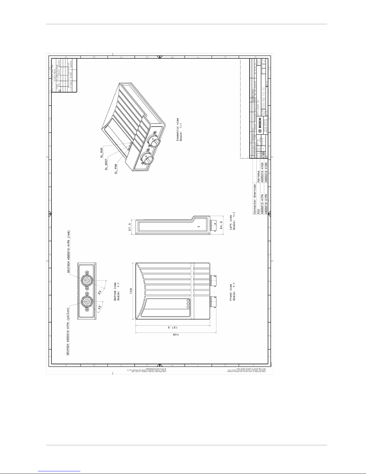
Mechanical Drawing | 7
Bosch Motorsport Data Logger C 60 21/108
7 Mechanical Drawing
Page 22
8 | Starting up the C 60
22/108 Data Logger C 60 Bosch Motorsport
8 Starting up the C 60
8.1 Before starting
Install the software required C 60 operation. It is developed for Windows 2000/XP/Vista/7.
Following software versions are used in this manual:
– C 60 setup, configuration and calibration: RaceCon 2.1.0
– Measurement data analysis: WinDarab V7
Set up the 100 Mbit Ethernet connection to the C 60.
– All three Ethernet ports of C 60 are internally connected by a network switch
– All Ethernet ports have ‘cable auto crossover’ functionality
Minimum wiring loom of the Life connector (red):
Pin Description
Pin 1+2+3 12 V supply voltage
Pin 4+5 GND supply voltage
Pin 6 Ethernet Tx+
Pin 7 Ethernet Tx-
Pin 8 Ethernet Rx+
Pin 9 Ethernet Rx-
Pin 10 Ethernet Screen
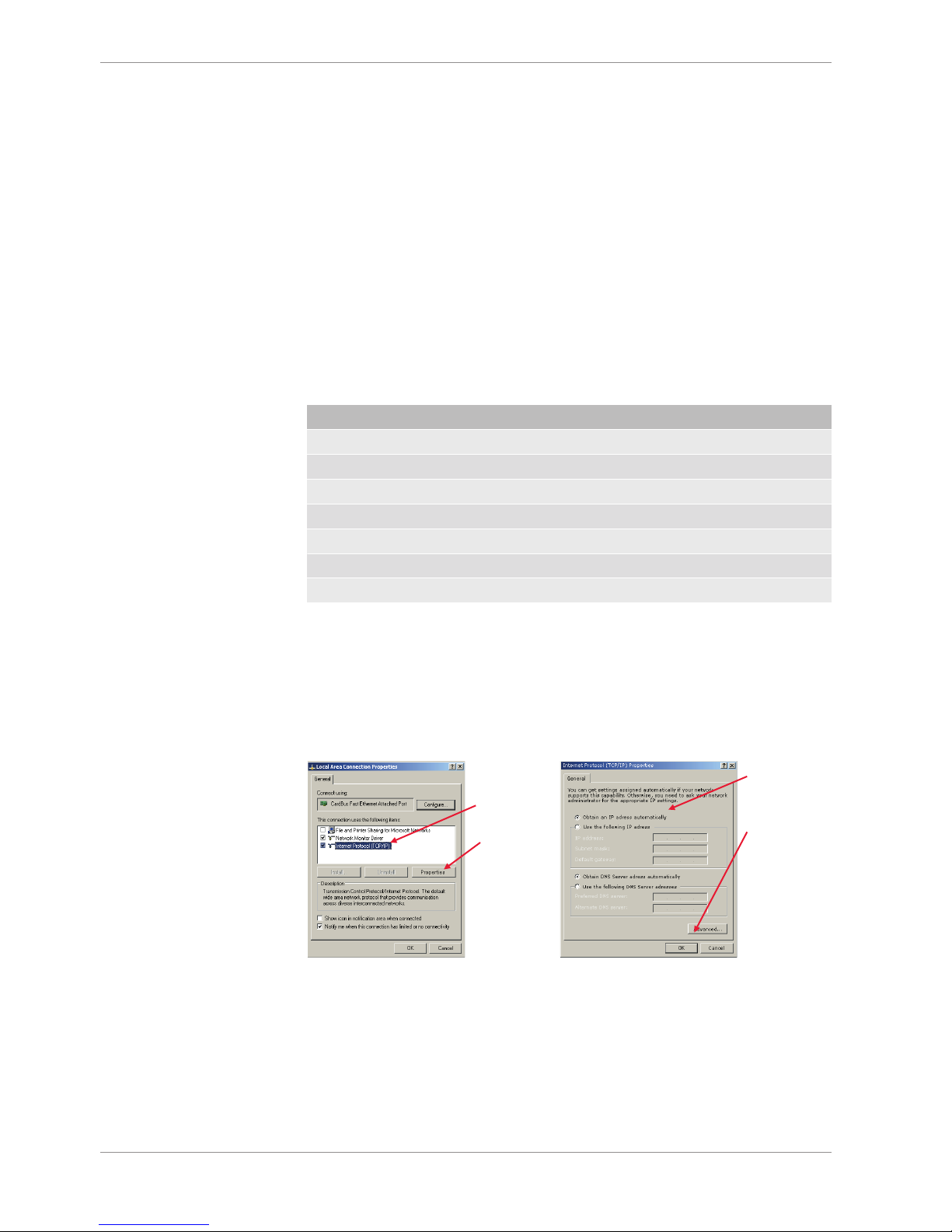
8.1.1 Setting up the network interface
The C 60 contains a DHCP server, network addresses can be assigned automatically to the
configuration PC. The IP address of C 60 is 10.10.0.207.
1. Switch off the PC’s firewall.
2. Set up the PC’s network interface as shown in the screenshots.
Select
‘Internet
Protocol
(TCP/IP)’
Click
‘Properties’
Select ‘Obtain
an IP address
automatically’
Click ‘OK’
when done
8.1.2 About RaceCon
RaceCon is an all integrated software tool for configuration and calibration of Bosch
Motorsport hardware products. It is used to set up, configure and calibrate the C 60.
For better understanding, Bosch Motorsport offers a video tutorial that explains many
functions of RaceCon. The video tutorial is available in the ‘Software Download’ section of
www.bosch-motorsport.com.
Page 23
Starting up the C 60 | 8
Bosch Motorsport Data Logger C 60 23/108
8.1.3 Connecting the Unit to RaceCon
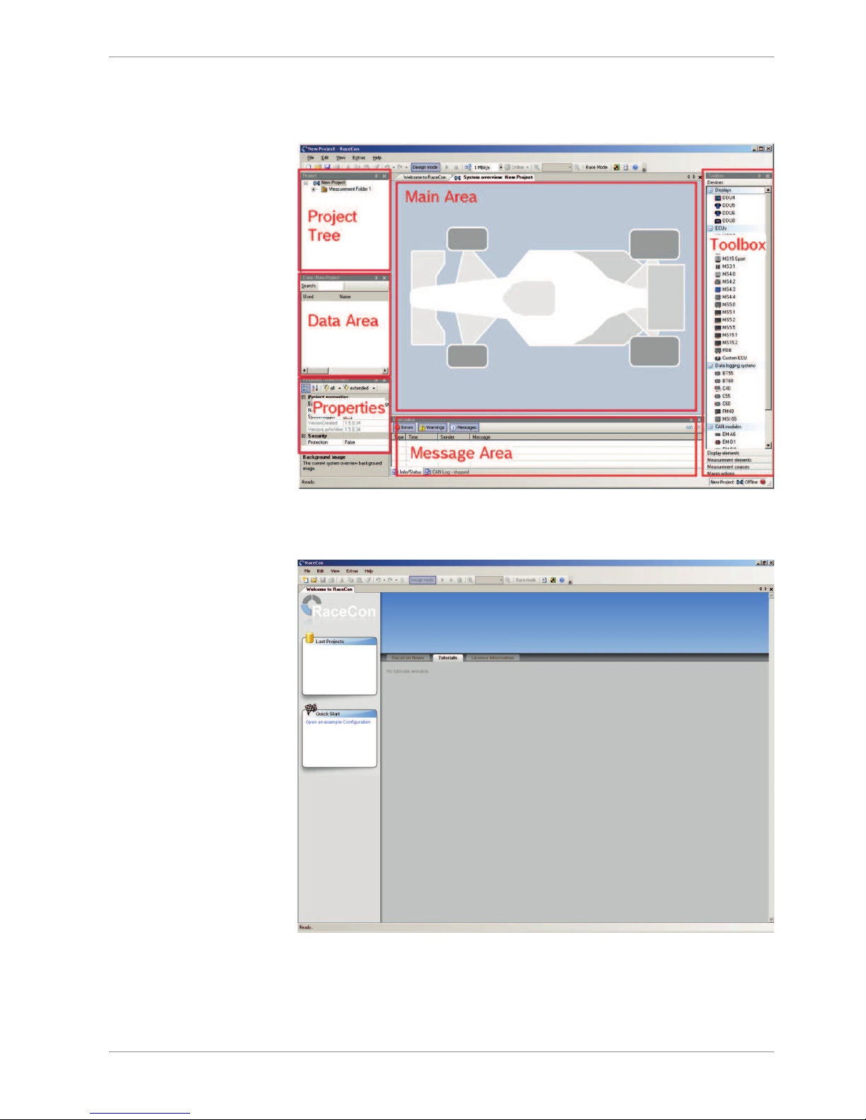
The following screenshot shows an overview of the RaceCon Main Screen with its areas.
All (sub-) windows are resizable and dockable.
1. Start the RaceCon software.
Page 24
8 | Starting up the C 60
24/108 Data Logger C 60 Bosch Motorsport
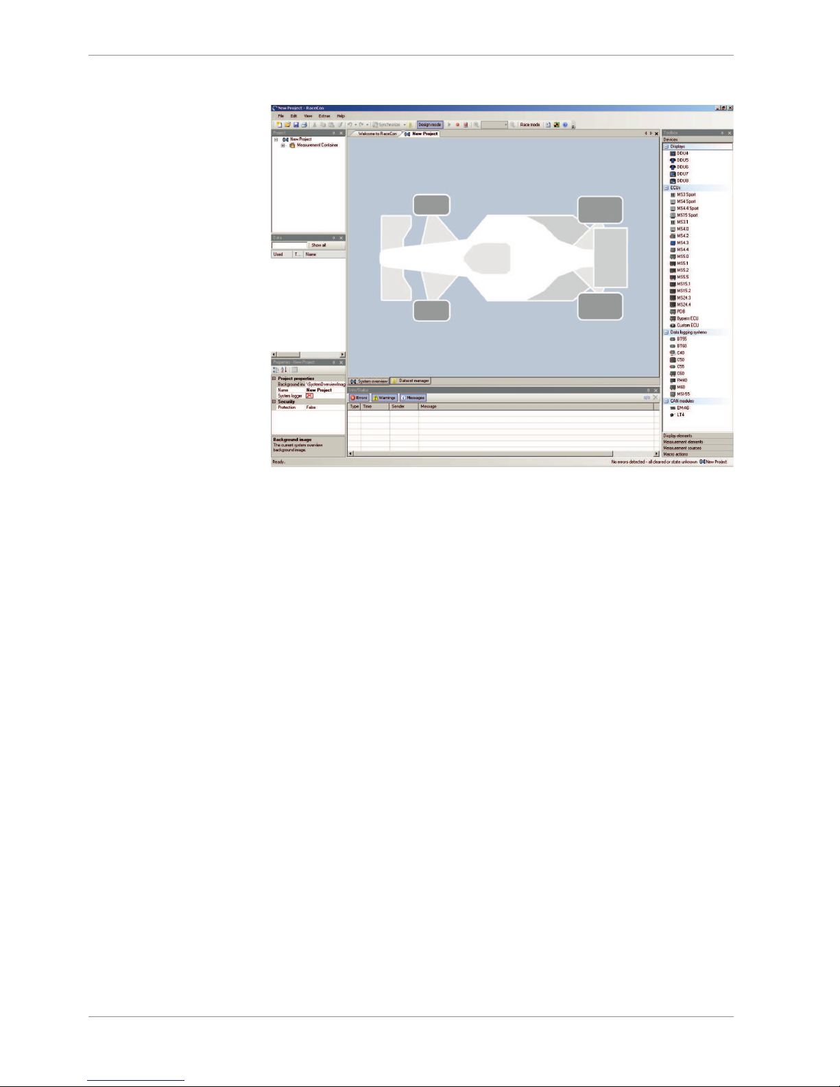
In the ‘File’ menu select ‘New’ to create a new project.
In the Toolbox select the C 60 and drag it into the Main Area. A pop up window to specify
the C 60 program archive appears.
1. An information shows that the archive is valid or not.
Select the program archive delivered with the C 60 (.PST file).
Click ‘Next’.
1. Select ‘Race track’.
2. Choose the way to switch display pages that fits to your hardware configuration.
3. Click ‘Finish’. The C 60 is inserted into the project and RaceCon tries to connect to the
device.
4. RaceCon detects configuration differences between the C 60 and the RaceCon project
and asks for permission for data download.
5. Click ‘OK’ to proceed.
The download starts and the C 60 carries out a reset.
After the reset RaceCon reconnects to the C 60. Local configuration on both the PC and C
60 match (Indicated by green background and dot). The C 60 is now connected to RaceCon.
Page 25

Starting up the C 60 | 8
Bosch Motorsport Data Logger C 60 25/108
8.2 Feature activation
– Optional software feature packages are available for the C 60 If you have purchased
an optional software feature package, it must be activated before it becomes operational.
– The feature activation status is stored permanently in the device and requires activat-
ing once only.
– As the activation key is device specific, a key delivered with one C 60 does not work
on any other C 60 .
– If you have not purchased an option package, the next steps can be skipped.
To activate a feature, double-click on ‘C 60’ in the Project Tree and click on the ‘Features
info’ tab in the Main Area.
The ‘C 60 features info’ window appears.
Double-click on the feature you want to activate. A feature unlock window appears.
Enter the activation key you received for this feature on this device and click ‘OK’ when
done. The feature’s status changes to ‘unlocked’.
Perform these steps to activate other features you purchased.
Switch the car’s ignition off and on again to cycle the power of C 60.
8.3 First recording (Quick start)
This chapter explains the configuration of the recording of the battery voltage channel.
See chapter ‘Recording and Telemetry [}79]’ for a detailed instruction to configure recordings.
This function requires the installation of Software Upgrade 1. For data recording on the C
60 , the software upgrade ‘C 60 Datalogger’ must be activated. See chapter ‘Feature activation’ for an instruction to activate software upgrades on C 60.
1. Expand the C 60 Project Tree by clicking ‘+’.
2. Expand the Logger Tree by clicking ‘+’.
3. Double-click on ‘Recording’.
4. The C 60 recording configuration area opens.
In C 60 Project Tree, click on ‘C 60’ to display the available measurement channels. In the
data window, scroll down to ‘ub’ (measurement channel for battery voltage).
Drag + drop the ‘ub’ measurement channel into the recording area.
Right-click on ‘C 60’ in the C 60 Project Tree and choose ‘Download configuration’.
The configuration download starts and the C 60 carries out a reset.
1. As we did not define global start conditions, recording starts immediately.
2. Start the WinDarab software.
3. Disconnect the C 60 network cable.
4. Click on the ‘Import/Export’ icon.
Page 26
8 | Starting up the C 60
26/108 Data Logger C 60 Bosch Motorsport
5. Select ‘Data logger C50/C55/C60/DDU7/DDU8’ and click ‘OK’ when done.
6. The ‘Read measurement Data’ dialog opens.
7. Click on ‘Modify’ button and select the base folder.
8. Choose ‘FTP’ as data transmission method.
9. Choose ‘XXXXXXXXXXX’ in the Vehicle dropdown list.
10. Activate ‘Auto save’.
11. Click ‘Save’ when done.
Connect the C 60 network cable. Data transmission from the C 60 starts automatically.
Measurement files are stored automatically in the base folder.
1. Click on ‘Close’ when transmission has finished.
2. Click on the Start button and choose ‘Open measurement file’.
3. Select the measurement files from the storage folder.
4. Click on ‘Open’.
5. Click in ‘New Desktop‘ to open a new measurement data window.
6. Drag the ‘ub’ measurement channel from the Channel list and drop it into the measurement data window. ‘ub’ measurement channel‘s graph is displayed.
NOTICE
For more detailed descriptions and instructions refer to the WinDarab V7 manual.
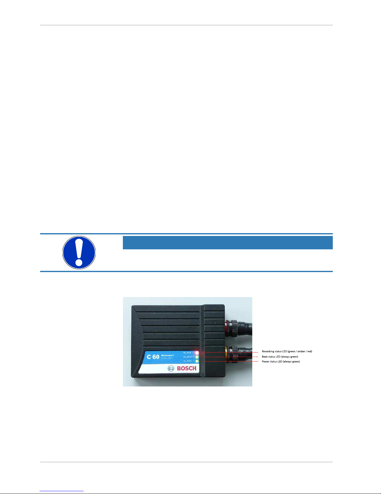
8.4 Status LEDs
Illustration1:
Page 27

Starting up the C 60 | 8
Bosch Motorsport Data Logger C 60 27/108
8.5 Set Time & Date
The C 60 is equipped with a real time clock which is supplied by an internal accumulator.
Once this accumulator is charged correctly by 12 V supply of the C 60, ‘Date & Time’ can
be programmed by RaceCon. We recommend min. 5 hours charge time.
Please connect the C 60 to the PC and click on ‘Set Date & Time’ in the Context menu of
the C 60.
Page 28
9 | CAN Bus
28/108 Data Logger C 60 Bosch Motorsport
9 CAN Bus
C 60 has two fully configurable CAN buses.
– Baudrate (125 kBit … 1 MBit)
– 11 Bit or 29 Bit identifiers
– Input configuration: Read messages from CAN bus and convert to C 60 measure-
ment/display variables. CAN bus supports row counter configuration.
– Output configuration: Write C 60 measurement variables to CAN messages, output
frequency and row counter are configurable, CAN gateway functionality (transfer from
one bus to the other).
9.1 CAN bus trivia
CAN message
– 11 Bit (standard) or 29 Bit (extended) identifier
– Up to 8 bytes of data payload
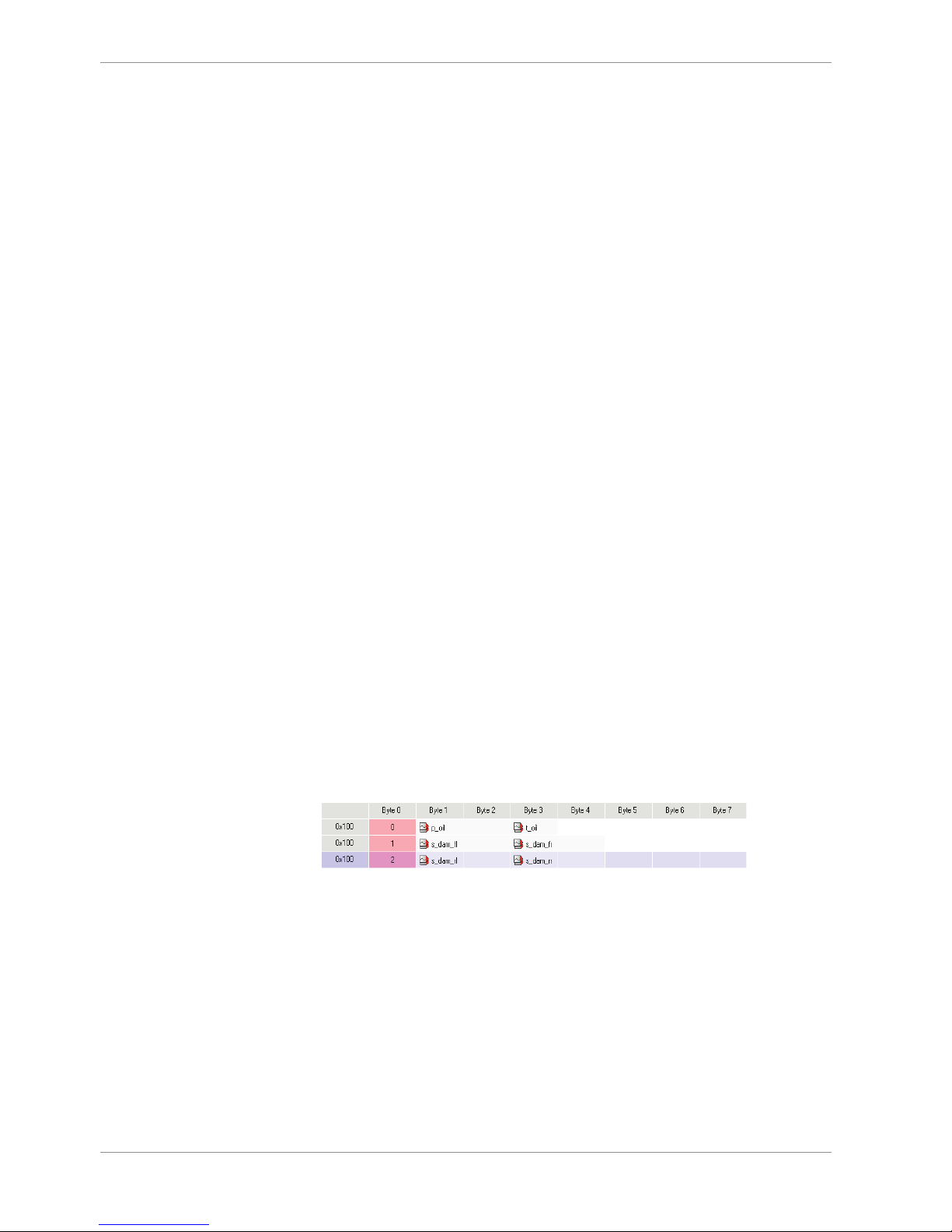
CAN bus
– Needs termination resistors (120 Ohm) in wiring harness
– All devices connected to the bus must use identical data rate
Configuration of C 60 bus data rate by double click on the CAN bus
in project tree (1 MBaud, 500 kBit, 250 kBit, 125 kBit)
Row counter concept
– Re-use (multiplex) of message identifiers
– One byte of message contains row counter
– 7 bytes payload remaining
– Position of row counter is configurable
Payload Area
Row
Row
Counter
Payload Area
Message
Id
9.2 CAN input
9.2.1 Input configuration
9.2.2 Create a new CAN channel
1. Right-click on CAN Input of desired bus (CAN1 or CAN2).
Page 29
CAN Bus | 9
Bosch Motorsport Data Logger C 60 29/108
2. Select ‘New CAN Channel’ from menu.
3. Insert name and description of channel.
4. Click ‘OK’ when done.
The channel is listed in the Data window and a CAN channel configuration window opens.
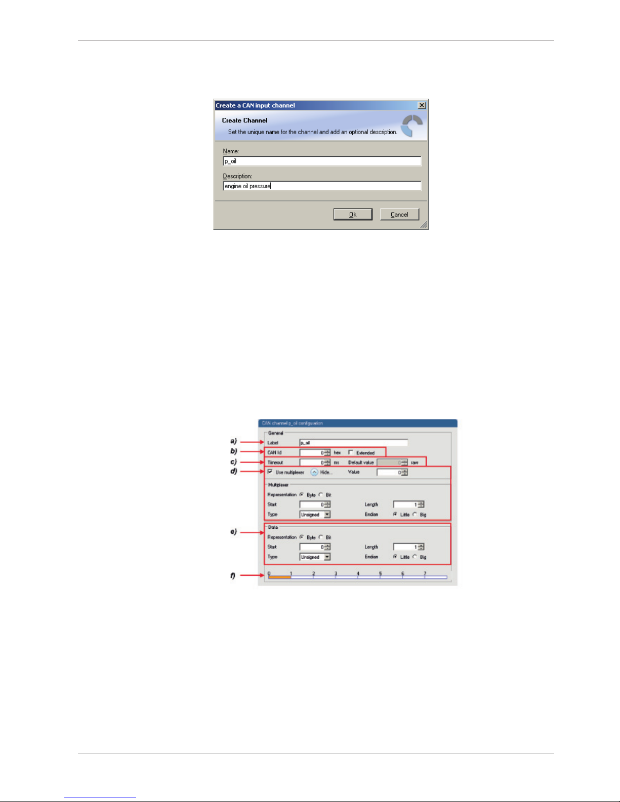
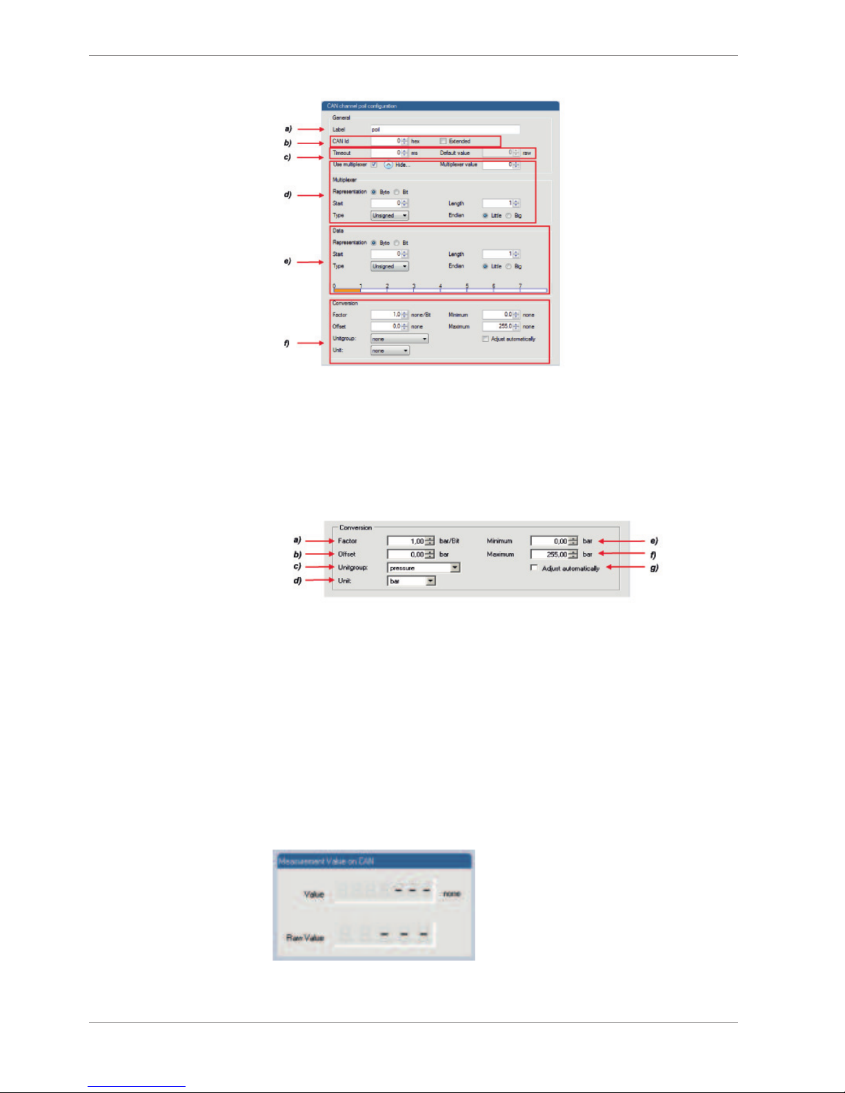
9.2.3 CAN channel configuration
9.2.4 Extracting data from CAN bus
Representation: Byte
Some CAN devices need to be addressed by a byte represented CAN channel. The address can be assigned in this window and is illustrated by a bargraph.
a) Enter name of the CAN-channel.
b) Enter CAN message ID. Check the box, if extended IDs (29 bit) are used.
c) If replacement values are used, specify time-out period and raw value.
d) Check the box, if a multiplexer (row counter) is used.
e) Enter data position, length and format.
f) The bargraph shows assignment of the bytes.
• Red colored fields show the assignment of the data bytes.
• Orange colored fields show the assignment of the multiplexer bytes.
Representation: Bit
Some CAN devices need to be addressed by a bit represented CAN channel. The address
can be assigned in this window and is illustrated by a matrix table.
Page 30
9 | CAN Bus
30/108 Data Logger C 60 Bosch Motorsport
a) Enter name of the CAN-channel.
b) Enter CAN message ID. Check the box, if extended IDs (29 bit) are used.
c) If replacement values are used, specify time-out period and raw value.
d) Check the box, if a multiplexer (row counter) is used.
e) Enter data position, length and format. The matrix table shows the assignment of the bits.
f) Enter a Conversation to get physical values
9.2.5 Conversion to physical values
a) Enter factor (gain) for conversion to physical value.
b) Enter offset for conversion to physical value.
c) Select type of physical value.
d) Select unit of physical value.
e) Enter minimum physical limit of the channel. (for manual setup)
f) Enter maximum physical limit of the channel. (for manual setup)
g) Check the box to automatically adjust the limits of the channel.
9.2.6 Special features
CAN analyzer functionality
This functionality is only available, if a MSA-Box (I & II) is used to connect the C 60 to the
PC. Choose the CAN bus that is connected to the MSA-Box to display the raw value and
the converted physical value here.
Page 31

CAN Bus | 9
Bosch Motorsport Data Logger C 60 31/108
Automatic creation of online measurement sheets
The CAN channel can be automatically inserted to a measurement sheet. Insert a name for
a new sheet or select an existing sheet from the listbox.
For an online view of the value measured by the C 60, insert the channel in an online
measurement sheet which is described in the next chapter.
9.2.7 Online view of CAN channels in vehicle
1. Double-click on ‘Sheet 1’ in Project Tree.
Measurement Sheet 1 is displayed in Main Area.
1. Click on ‘Measurement elements’ in the Toolbox.
2. Drag the desired Measurement element (e.g. Numeric Indicator) and drop it on the
Measurement Sheet.
1. Click on folder ‘CAN Input’ of desired CAN bus to display available channels.
2. Drag desired Measurement channel and drop it on the Measurement element.
The measurement element displays the values of the assigned channel.
1. Connect PC to the vehicle and switch to ‘Race Mode’ by clicking ‘F11’ on the keyboard to display online data.
9.2.8 Import a CAN database (DBC) file
1. Right-click on CAN Input of desired bus (CAN1 or CAN2).
2. Select ‘Import DBC file’ from menu.
A file browser opens.
3. Select DBC file to import and click ‘OK’ when done.
A channel import window opens.
Page 32

9 | CAN Bus
32/108 Data Logger C 60 Bosch Motorsport
4. Select desired channels on the left and use the ‘Add’ button to add them to import
list.
5. Click ‘OK’ when complete.
The channels are inserted in the Data window.
9.2.9 Export RaceCon CAN configuration
1. Right-click on CAN Input of desired bus (CAN1 or CAN2).
2. Select ‘Export…’ from menu. An ‘Export Selection’ window opens.
3. Specify the filename.
4. Click ‘OK’ when done.
9.2.10 Import RaceCon CAN configuration
1. Right-click on CAN Input of desired bus (CAN1 or CAN2).
2. Select ‘Import…’ from menu.
A file browser opens.
3. Select the input file and click ‘OK’.
An ‘Import Selection’ window opens.
1. Select channels to import.
2. Drag and drop the channel to ‘CAN Input’ of desired CAN bus on right hand side.
Page 33

CAN Bus | 9
Bosch Motorsport Data Logger C 60 33/108
3. Click ‘Next’.
If a measurement channel belongs to more than one source (e.g. C 60 and ECU MS
5.1), the ‘Solve Label Ambiguity’ window opens.
4. Assign the ambiguous channels to the desired source.
5. Click ‘Finish’.
9.2.11 Export to dbc file
Click on this option to save the CAN configuration to a Vector dbc file format. It will open
an explorer window where the dbc file can be saved on the harddisc.
9.3 CAN output
9.3.1 Output configuratin
9.3.2 Create a new CAN output message channel
1. Right-click on CAN Output of desired bus (CAN1 or CAN2).
2. Select ‘New CAN Message’ from menu.
The ‘Create new CAN message’ window opens.
3. Enter name of message, CAN-Id and Grid (output interval).
4. Optionally, specify a row counter (multiplexer).
5. Click ‘OK’ when done.
A CAN message configuration window opens in the Main Area.
1. Click on ‘C 60’ in the C 60 Project Tree to display all labels.
2. Select the desired measurement channel and drop it on message’s bytes.
The measurement channel is assigned to the CAN message.
A double Click on one of the defined CAN channels opens the following dialogue:
Page 34

9 | CAN Bus
34/108 Data Logger C 60 Bosch Motorsport
In this dialogue additional settings are possible:
– Representation: Also a Bitwise CAN signal can be defined. Please define position and
length in this case.
– Quantization: Physical values can be calculated by entering Factor/Offset. Signed and
unsigned is optional.
9.3.3 Edit CAN Message Multiplexer settings
1. Click “Use multiplexer”, the Option “Hide” opens the multiplexer settings.
Representation: Choose Byte or Bit Type of multiplexer
Start, Length: Define start position and length of multiplexer (Byte or Bitwise possible)
Endianness: Define Byte order (Little Endian –LB, HB, Big Endian –HB, LB)
9.3.4 Export RaceCon CAN configuration
1. Right-click on CAN Output of desired bus (CAN1 or CAN2).
2. Select ‘Export…’ from menu. The ‘Export Selection’ window opens.
3. Specify the filename.
4. Click ‘OK’ when done.
Page 35

CAN Bus | 9
Bosch Motorsport Data Logger C 60 35/108
9.3.5 Import RaceCon configuration
1. Click right on CAN Output of desired bus (CAN1 or CAN2).
2. Select ‘Import…’ from menu.
A file browser opens.
3. Select the input file and click ‘OK’.
An ‘Import Selection’ window opens.
1. Select channels to import.
2. Drag and drop the channel to ‘CAN Output’ of desired CAN bus on right hand side.
3. Click ‘Next’.
If a measurement channel belongs to more than one source (e.g. C 60 and ECU MS
5.1), the ‘Solve Label Ambiguity’ window opens.
1. Assign the ambiguous channels to the desired source.
2. Click ‘Finish’.
Page 36

10 | Analog and Frequency Inputs
36/108 Data Logger C 60 Bosch Motorsport
10 Analog and Frequency Inputs
10.1 Features
24 analog inputs with Software Upgrade 2; 4 analog inputs without upgrade
– 0 … 5 V
– 12 bit A/D converter
– Switchable 3.01 kOhm pull-up resistor
– 8 kHz acquisition rate, up to 1 kHz recording rate
– Linear phase digital filter
4 frequency inputs with Software Upgrade 2; no frequency inputs without upgrade
– 5 V Hall-effect type, 2.5 V trigger level
– 20 kHz max. frequency
– 10 ms measurement window
4 PWM outputs
– Low-side switch
– Up to 2 A each
– Output frequency selectable
10.2 Analog inputs
Measurement channels
For each analog channel, several ‘subchannels’ are available.
Measurement labels with the characters ‘raw’ show the exact values in mV.
Measurement labels with the characters ‘_fi’ show filtered values.
The word ‘name’ in the table is a placeholder for the channel’s name.
Page 37

Analog and Frequency Inputs | 10
Bosch Motorsport Data Logger C 60 37/108
Measurement label Function
raw_name mV value of sensor
raw_name_fi filtered mV value of sensor
name physical value of sensor
name_fi filtered physical value
Filtered channels are routed through digital low pass filters:
– C 60 uses A/D converter oversampling and digital filtering to recording rate
– Digital filters eliminate ‘out-of-band’ noise
– Cut-off frequency automatically adjusted to recording rate
– Linear phase - no signal distortion
– Latency compensation - no filter delay in recorded data
10.2.1 Measurement channels
10.3 Configuring inputs
10.3.1 Configuring a predefined Bosch sensor with the
'Bosch Sensor Wizard'
1. Click on ‘Measurement Sources’ in the Toolbox.
2. Expand the list of ‘I/O Channels’ by clicking on ‘+’ in the C 60 Project Tree.
3. Drag the ‘Bosch Sensor Wizard’ from the Toolbox and drop it on the desired analog
input channel in the C 60 Project Tree. The ‘Bosch Sensor Wizard’ opens.
Page 38

10 | Analog and Frequency Inputs
38/108 Data Logger C 60 Bosch Motorsport
3rd: Select the
exact type
Opens sensor’s
datasheet
2nd: Narrow your
choice by
choosing a type
These calibration
values will be
used
1st: Choose
the sensor’s
category
4. Click ‘Finish’ when done.
5. The ‘Create channel’ window opens.
6. Enter channel name and description.
7. Click ‘Ok’ when done.
The channel is inserted into the C 60 Project Tree.
Calculation of
physical value with
characteristic curve
Input pin
Pull-up
resistor is
activated
Channel
is linked
to
ANA03
Available measurements for channel:
Measurement label Function
raw_name mV value of sensor
raw_name_fi filtered mV value of sensor
name physical value of sensor
name_fi filtered physical value
Page 39

Analog and Frequency Inputs | 10
Bosch Motorsport Data Logger C 60 39/108
10.3.2 Configuring a generic linear sensor
Example: Acceleration sensor 5 g
From sensor data sheet – operating characteristics:
Sensitivity 400 mV/g, Offset 2500 mV
The sensor has a linear output signal with sensitivity and offset
1. Click on ‘Measurement Sources’ in the Toolbox.
2. Expand the list of ‘I/O Channels’ by clicking on ‘+’ in the C 60 Project Tree.
3. Drag the ‘Sensitivity/Offset’ analog signal source from the Toolbox and drop it on the
desired analog input channel in the C 60 Project Tree. A ‘Sensitivity/Offset Wizard’
opens.
4. To activate the internal pullup-resistor, check the box.
The internal pullup-resistor is used to get a 5 V signal at the analog channel of the C
60.
It allows you to use a push-button.
The fixed value of the internal pullup-resistor is 3010 Ohm. If using an additional external pullup-resistor, set up the overall resistance.
5. Click ‘Next’ when done.
The second part of the ‘Sensitivity/Offset Wizard’ opens.
Page 40

10 | Analog and Frequency Inputs
40/108 Data Logger C 60 Bosch Motorsport
Choose unit
group and unit
of physical value
Enter values
from sensor
datasheet
Electrical
(pin) value
Physical
(channel)
value
6. Click ‘Next’ when done. The third part of the ‘Sensitivity/Offset Wizard’ opens.
NOTICE
Working with automatically created measurement sheets is explained in chapter ‘Setting up an online measurement’.
7. Click ‘Finish’ when done.
8. Enter channel name and description.
9. Click ‘OK’ when done.
The channel is inserted into the C 60 Project Tree.
Input pin
Pull-up
resistor is
deactivated
Sensitivity
and Offset
value for
sensor
Adjustment
is enabled
Channel is
linked to
ANA04
Available measurements for channel:
Page 41

Analog and Frequency Inputs | 10
Bosch Motorsport Data Logger C 60 41/108
Measurement label Function
raw_name mV value of sensor
raw_name_fi filtered mV value of sensor
name physical value of sensor
name_fi filtered physical value
10.3.3 Configuring a generic non-linear sensor
Example: Thermistor 5 kOhm
– From sensor data sheet: resistance values over temperature
– The sensor has a nonlinear behaviour
– Use characteristic curve for linearization
– Input voltage is the ratio between pull-up resistor and thermistor
Pin
Thermistor
+5V
3 kOhm
1. Click ‘Measurement Sources’ in the Toolbox.
2. Expand the list of ‘I/O Channels’ by clicking on ‘+’ in the C 60 Project Tree.
3. Drag the ‘Characteristic Curve’ analogue signal source from the Toolbox and drop it
on the desired analogue input channel in the C 60 Project Tree. A ‘Characteristic
Curve Wizard’ opens.
4. To activate the internal pull up-resistor, check the box.
The C 60 pull up-resistor is used to get a 5V signal at the analogue channel of the C
60.
It allows you to use a push-button.
The fixed value of the internal pull up-resistor is 3010 Ohm. If using an additional external pull up-resistor, set up the overall resistance.
Page 42

10 | Analog and Frequency Inputs
42/108 Data Logger C 60 Bosch Motorsport
5. Click ‘Next’ when done.
The second part of the ‘Sensitivity/Offset Wizard’ opens.
Select physical unit.
Physical
(channel)
value
Choose ‘Ohm’ to enter
datasheet values directly.
Enter
resistance/temperature
pairs from sensor datasheet
here (The 3.01 kOhm pullupresistor is automatically
taken into account)
6. Click ‘Next’ when done.
The third part of the ‘Characteristic Curve Wizard’ opens.
Enter physical limits
of the channel
Choose data type of the
measurement variable
This sensor does not
need offset calibration
Physical
limits of
channel
Enter name to
automatically create a new
measurement sheet
NOTICE
Working with automatically created measurement sheets is explained in chapter ‘Setting up an online measurement’.
7. Click ‘Finish’ when done.
8. Enter channel name and description.
Page 43

Analog and Frequency Inputs | 10
Bosch Motorsport Data Logger C 60 43/108
9. Click ‘OK’ when done.
The channel is inserted into the C 60 Project Tree.
Input pin
Pull-up
resistor is
activated
Characteristic
curve for
sensor
Adjustment
is disabled
Channel is
linked to
ANA05
Available measurements for channel:
Measurement label Function
raw_name mV value of sensor
raw_name_fi filtered mV value of sensor
name physical value of sensor
name_fi filtered physical value
10.3.4 Configuring a multipoint adjustment
Example: Measurement of wheel force
– Physical property ‘wheel force’ not directly measureable
– Load transfer through suspension kinematics
– Physical value at sensor position defined by vehicle
– Curve definition by online adjustment at vehicle
1. Click on ‘Measurement Sources’ in the Toolbox.
2. Expand the list of ‘I/O Channels’ by clicking on ‘+’ in the C 60 Project Tree.
3. Drag the ‘Multipoint Adjustment’ analog signal source from the Toolbox and drop it
on the desired analog input channel in the C 60 Project Tree.
4. A ‘Multipoint Adjustment Wizard’ opens.
5. To activate the internal pullup-resistor, check the box.
Page 44

10 | Analog and Frequency Inputs
44/108 Data Logger C 60 Bosch Motorsport
The internal pullup-resistor is used to get a 5 V signal at the analog channel of the C
60.
It allows you to use a push-button.
The fixed value of the internal pullup-resistor is 3010 ohm. If using an additional external pullup-resistor, set up the overall resistance.
6. Click ‘Next’ when done. The second part of the ‘Multipoint Adjustment Wizard’ opens.
7. Click ‘Next’ when done. The third part of the ‘Multipoint Adjustment Wizard’ opens.
Enter physical
limits of the sensor
Choose data type of
the measurement
variable
Enable additonal
online calibration
Physical
limits of
channel
Enter name to
automatically create a new
measurement sheet
NOTICE
Working with automatically created measurement sheet is explained
in chapter ‘Setting up an online measurement’.
Page 45

Analog and Frequency Inputs | 10
Bosch Motorsport Data Logger C 60 45/108
8. Click ‘Finish’ when done.
9. Enter channel name and description.
10. Click ‘OK’ when done.
The channel is inserted into the C 60 Project Tree.
Input pin
Pull-up
resistor is
deactivated
Characteristic
curve for
sensor
Adjustment
is enabled
Channel is
linked to
ANA06
Available measurements for channel:
Measurement label Function
raw_name mV value of sensor
raw_name_fi filtered mV value of sensor
name physical value of sensor
name_fi filtered physical value
Online definition of the curve is covered in the chapter ‘Online calibration of measurement
channels [}73]’ of this manual.
10.3.5 Digital filter details
C 60 uses A/D converter oversampling and digital filtering to recording rate.
Digital filters eliminate ‘out-of-band’ noise
Page 46

10 | Analog and Frequency Inputs
46/108 Data Logger C 60 Bosch Motorsport
Cut-off frequency automatically adjusted to recording rate
Example:
– 100 Hz recording rate (10 ms)
– < 40 Hz pass band (> 99 %)
– 50 Hz stop band (< 1 %)
Linear phase – no signal distortion
0 500 1000 1500 2000 2500 3000
-2
-1.5
-1
-0.5
0
0.5
1
1.5
2
Abtastwerte (roh)
Wert
10000Hz Abtastrate
0 5 10 15 20 25 30
-1.5
-1
-0.5
0
0.5
1
1.5
Abtastwerte (gefiltert)
Wert
100Hz Abtastrate
0 5 10 15 20 25 30
-1.5
-1
-0.5
0
0.5
1
1.5
Abtastwerte (dezimiert)
Wert
100Hz Abtastrate
Sensor signal with noise
Recorded signal 100Hz
(unfiltered)
Recorded signal 100Hz
(filtered)
Latency compensation – no filter delay in recorded data
– Filtering is (smart) averaging over several samples
– Filtered signal is delayed with respect to real time signal
– C 60 filters have constant, frequency independent delay
– Delay (e.g. 22 samples at 10 ms) is corrected during recording
– No delay filtered vs. unfiltered in recorded data
– Correction is (of course) not possible for real time data (display, online, PWM out)
– Use filtered data for recording, use unfiltered data for real-time
10.3.6 Configuring a frequency input
This function requires the installation of Software Upgrade 2.
Example: measurement of wheel speed
– Pulse wheel attached to wheel
– Each passing tooth of pulse wheel triggers hall sensor
– Calculation of wheel speed with wheel circumference
Page 47

Analog and Frequency Inputs | 10
Bosch Motorsport Data Logger C 60 47/108
1. Click ‘Measurement Sources’ in the Toolbox.
2. Expand the list of ‘I/O Channels’ by clicking on ‘+’ in the C 60 Project Tree.
3. Drag the ‘Velocity’ digital signal source from the Toolbox and drop it on the desired
‘REV’ input channel in the C 60 Project Tree.
4. The ‘Velocity Wizard’ opens.
Choose data type of the
measurement variable
Circumference of wheel for
speed calculation
Special functionality for sensors
with frequency offset (e.g.
Correvit) Set to ‘0’ for wheelspeed
measurement
Number of teeth on the pulse
wheel
Enter name to automatically
create a new measurement
sheet
5. Click ‘Finish’ when done.
6. Enter channel name and description.
7. Click ‘OK’ when done.
The channel is inserted into the C 60 Project Tree.
Input pin
has hall
interface
Number of
teeth
Wheel
circumference
Channel is
linked to
REV01
Available measurements for channel:
Measurement label Function
raw_name mV value of sensor
raw_name_fi filtered mV value of sensor
name physical value of sensor
name_fi filtered physical value
Page 48

10 | Analog and Frequency Inputs
48/108 Data Logger C 60 Bosch Motorsport
NOTICE
Measurement of ‘Revolution’ is similar.
10.4 Computed sources
10.4.1 Configuring computed sources
Computed sources receive data from a measurement channel rather than an input pin.
– Sensitivity/Offset calculation on input channel
– Characteristic curve calculation on input channel
– Computed vehicle speed
– PWM output control (covered in a special section)
– Lap trigger (covered in a special section)
Example: Sensitivity/offset calculation on input channel
1. Click ‘Measurement Sources’ in the Toolbox.
2. Drag the ‘Sensitivity/Offset’ computed source from the Toolbox and drop it on ‘Computed Channels’ in the C 60 Project Tree.
A ‘Computed Sensitivity/Offset Wizard’ opens.
Choose unit group
a
nd unit of output
Enter sensitivity and offset
o
f conversion formula
Choose input
c
hannel
3. Click ‘Next’ when done.
4. The second part of the ‘Computed Sensitivity/Offset Wizard’ opens.
Page 49

Analog and Frequency Inputs | 10
Bosch Motorsport Data Logger C 60 49/108
Enter physical limits
of the channel
Choose data type of
the measurement
variable
Check the box to force
the channel’s
quantization if the
quantization should be a
fixed value in the whole
CAN system
Physical
limits of
channel
Enter name to
automatically create a new
measurement sheet
NOTICE
Working with automatically created measurement sheets is explained in chapter ‘Setting up an online measurement’.
5. Click ‘Finish’ when done.
6. Enter channel name and description.
7. Click ‘OK’ when done. The channel is inserted into the C 60 Project Tree.
10.5 Hysteresis
The hysteresis function avoids the high-frequent switchover of the measurement channel
value. The hysteresis can be adjusted for each input measurement channel individually
and can be used for further processing.
1. Click ‘Measurement Sources’ in the Toolbox.
2. Drag the ‘Hysteresis’ computed source from the Toolbox and drop it on ‘Computed
Channels’ in the C 60 Project Tree.
A ‘Hysteresis Wizard’ opens.
Page 50

10 | Analog and Frequency Inputs
50/108 Data Logger C 60 Bosch Motorsport
a) Choose input measurement channel.
b) Choose unit group and unit of output.
c) Enter output value of state A in the unit selected in b).
d) Enter threshold value when state changes from A to B.
e) Enter delay time when state changes from A to B.
f) Enter output value of state B in the unit selected in b).
g) Enter threshold value when state changes from B to A.
h) Enter delay time when state changes from B to A.
i) Enter time when the hysteresis function is activated after vehicle’s startup.
j) Enter the channel’s state (A or B) at startup.
3. Click ‘Next’ when done.
The second part of the ‘Hysteresis Wizard’ opens.
4. Click ‘Finish’ when done.
5. Enter channel name and description.
6. Click ‘OK’ when done.
The channel is inserted into the C 60 Project Tree.
Page 51

Analog and Frequency Inputs | 10
Bosch Motorsport Data Logger C 60 51/108
b)
a) Channels available in computed sources.
b) Available measurements for channel.
c) Calculation of hysteresis channel.
a)
c)
10.5.1 Special functionality: vehicle speed
This functionality allows:
– high performance vehicle owners to measure wheel spin under acceleration and
wheel slip/lock under braking.
– calculating vehicle ‘speed over ground’.
Vehicle speed calculation function
– Calculating vehicle speed of 2 wheel drive: (Wheel speeds of non-driven axle as input)
Calculated speed is average of both speeds if speed difference between wheels <
limit.
Calculated speed is maximum of both speeds if speed difference between wheels >
limit.
– Calculating vehicle speed of 4 wheel drive: (Wheel speeds of all wheels as input)
Calculated speed is speed of 2nd fastest wheel.
10.5.2 Setting up calculated speed
1. Click on tab ‘System Overview’.
2. Click on ‘Measurement Sources’ in the Toolbox.
3. Drag the ‘Speed’ computed source from the Toolbox and drop it on ‘Computed
Channels’ in the C 60 Project Tree. Do not drop it on ‘C 60’!
Page 52

10 | Analog and Frequency Inputs
52/108 Data Logger C 60 Bosch Motorsport
Drag + Drop
A ‘Calculated Speed Wizard’ opens.
Choose driven axle
Choose input source
(
internal / external)
Choose individual wheel speed
c
hannels
Set limit for speed difference
f
or calculation
Choose device
4. Click ‘Finish’ when done.
The speed calculation is inserted into the C 60 Project Tree.
Configuration
w
indow
Measurement
c
hannels
c
alculated
s
peed and
c
alculated
d
istance
Speed
c
alculation
i
n DDU 8
P
roject Tree
10.6 Configuring PWM outputs
PWM
– Pulse Width Modulation
– Output frequency is constant
– ‘On time’ (duty cycle) controlled by input channel
Page 53

Analog and Frequency Inputs | 10
Bosch Motorsport Data Logger C 60 53/108
C 60 has 4 PWM outputs
– Low-side switch
– Up to 2 A each
– Selectable output frequency
– Duty cycle controlled by characteristic curve
U
out
Time
Output frequency
Duty cycle 20%
(
switch closed)
Output frequency
Time
U
out
Duty cycle 80%
10.6.1 Configuring a PWM output
1. Click on ‘Measurement Sources’ in the Toolbox.
2. Drag the ‘PWM Out’ computed source from the Toolbox and drop it on the desired
‘PWM_OUT’ channel in the C 60 Project Tree.
3. A ‘PWM Out Wizard’ opens.
Choose output frequency
Define characteristic curve
Choose input
channel
Enter name to
automatically create a new
measurement sheet
Page 54

10 | Analog and Frequency Inputs
54/108 Data Logger C 60 Bosch Motorsport
NOTICE
Working with automatically created measurement sheets is explained in chapter ‘Setting up an online measurement’.
NOTICE
Choosing a filtered channel as an input for ‘PWM_OUT’ will cause
delayed reaction due to the delay introduced by the digital filter.
Use unfiltered values for this purpose.
NOTICE
The ‘power-on’ state of the PWM output is ‘switch open’ (0% duty
cycle).
4. Click ‘Finish’ when done.
5. Enter channel name and description.
6. Click ‘OK’ when done.
The channel is inserted into the C 60 Project Tree.
Characteristic
c
urve
Output
f
requency
Channel is
l
inked to
P
WM_OUT02
Measurement
c
hannels
Measurement label Function
pwm_err_ls_out_01_OL PWM output 1 error open load
pwm_err_ls_out_01_OT PWM output 1 error over temperature
pwm_err_ls_out_01_SCB PWM output 1 error short circuit to battery
pwm_err_ls_out_01_SCG PWM output 1 error short circuit to GND
Table1: Diagnostic channels
NOTICE
The diagnosis of PWM output 2-4 is similar.
Page 55

Analog and Frequency Inputs | 10
Bosch Motorsport Data Logger C 60 55/108
10.7 Analog inputs
10.7.1 Measurement channels
For each analog channel, several ‘subchannels’ are available.
Measurement labels with the characters ‘raw’ show the exact values in mV.
Measurement labels with the characters ‘_fi’ show filtered values.
The word ‘name’ in the table is a placeholder for the channel’s name.
Measurement label Function
raw_name mV value of sensor
raw_name_fi filtered mV value of sensor
name physical value of sensor
name_fi filtered physical value
Filtered channels are routed through digital low pass filters:
– C 60 uses A/D converter oversampling and digital filtering to recording rate
– Digital filters eliminate ‘out-of-band’ noise
– Cut-off frequency automatically adjusted to recording rate
– Linear phase – no signal distortion
– Latency compensation – no filter delay in recorded data
10.8 Configuring inputs
10.8.1 Configuring a predefined Bosch sensor with the
'Bosch Sensor Wizard'
1. Click on ‘Measurement Sources’ in the Toolbox.
2. Expand the list of ‘I/O Channels’ by clicking on ‘+’ in the C 60 Project Tree.
1. Drag the ‘Bosch Sensor Wizard’ from the Toolbox and drop it on the desired analog
input channel in the C 60 Project Tree. The ‘Bosch Sensor Wizard’ opens.
3rd: Select the
exact type
Opens sensor’s
datasheet
2nd: Narrow your
choice by
choosing a type
These calibration
values will be
used
1st: Choose
the sensor’s
category
2. Click ‘Finish’ when done.
Page 56

10 | Analog and Frequency Inputs
56/108 Data Logger C 60 Bosch Motorsport
3. The ‘Create channel’ window opens.
4. Enter channel name and description.
1. Click ‘Ok’ when done.
The channel is inserted into the C 60 Project Tree.
Available measurements for channel:
Measurement label Function
raw_name mV value of sensor
raw_name_fi filtered mV value of sensor
name physical value of sensor
name_fi filtered physical value
10.8.2 Configuring a generic linear sensor
Example: Acceleration sensor 5 g
From sensor data sheet – operating characteristics:
Sensitivity 400 mV/g, Offset 2500 mV
The sensor has a linear output signal with sensitivity and offset
1. Click on ‘Measurement Sources’ in the Toolbox.
2. Expand the list of ‘I/O Channels’ by clicking on ‘+’ in the C 60 Project Tree.
3. Drag the ‘Sensitivity/Offset’ analog signal source from the Toolbox and drop it on the
desired analog input channel in the C 60 Project Tree. A ‘Sensitivity/Offset Wizard’
opens.
4. To activate the internal pullup-resistor, check the box.
The internal pullup-resistor is used to get a 5 V signal at the analog channel of the C
60.
It allows you to use a push-button.
The fixed value of the internal pullup-resistor is 3010 Ohm. If using an additional external pullup-resistor, set up the overall resistance.
Page 57

Analog and Frequency Inputs | 10
Bosch Motorsport Data Logger C 60 57/108
5. Click ‘Next’ when done.
The second part of the ‘Sensitivity/Offset Wizard’ opens.
Choose unit
group and unit
of physical value
Enter values
from sensor
datasheet
Electrical
(pin) value
Physical
(channel)
value
6. Click ‘Next’ when done. The third part of the ‘Sensitivity/Offset Wizard’ opens.
NOTICE
Working with automatically created measurement sheets is explained in chapter ‘Setting up an online measurement’.
7. Click ‘Finish’ when done.
8. Enter channel name and description.
9. Click ‘OK’ when done.
Page 58

10 | Analog and Frequency Inputs
58/108 Data Logger C 60 Bosch Motorsport
The channel is inserted into the C 60 Project Tree.
Available measurements for channel:
Measurement label Function
raw_name mV value of sensor
raw_name_fi filtered mV value of sensor
name physical value of sensor
name_fi filtered physical value
10.8.3 Configuring a generic non-linear sensor
Example: Thermistor 5 kOhm
– From sensor data sheet: resistance values over temperature
– The sensor has a nonlinear behaviour
– Use characteristic curve for linearization
– Input voltage is the ratio between pull-up resistor and thermistor
Pin
Thermistor
+5V
3 kOhm
1. Click ‘Measurement Sources’ in the Toolbox.
2. Expand the list of ‘I/O Channels’ by clicking on ‘+’ in the C 60 Project Tree.
3. Drag the ‘Characteristic Curve’ analogue signal source from the Toolbox and drop it
on the desired analogue input channel in the C 60 Project Tree. A ‘Characteristic
Curve Wizard’ opens.
4. To activate the internal pull up-resistor, check the box.
The C 60 pull up-resistor is used to get a 5V signal at the analogue channel of the C
60.
It allows you to use a push-button.
The fixed value of the internal pull up-resistor is 3010 Ohm. If using an additional external pull up-resistor, set up the overall resistance.
Page 59

Analog and Frequency Inputs | 10
Bosch Motorsport Data Logger C 60 59/108
5. Click ‘Next’ when done.
The second part of the ‘Sensitivity/Offset Wizard’ opens.
Select physical unit.
Physical
(channel)
value
Choose ‘Ohm’ to enter
datasheet values directly.
Enter
resistance/temperature
pairs from sensor datasheet
here (The 3.01 kOhm pullupresistor is automatically
taken into account)
6. Click ‘Next’ when done.
The third part of the ‘Characteristic Curve Wizard’ opens.
Enter physical limits
of the channel
Choose data type of the
measurement variable
This sensor does not
need offset calibration
Physical
limits of
channel
Enter name to
automatically create a new
measurement sheet
NOTICE
Working with automatically created measurement sheets is explained in chapter ‘Setting up an online measurement’.
7. Click ‘Finish’ when done.
8. Enter channel name and description.
Page 60

10 | Analog and Frequency Inputs
60/108 Data Logger C 60 Bosch Motorsport
9. Click ‘OK’ when done.
The channel is inserted into the C 60 Project Tree.
Available measurements for channel:
Measurement label Function
raw_name mV value of sensor
raw_name_fi filtered mV value of sensor
name physical value of sensor
name_fi filtered physical value
10.8.4 Configuring a multipoint adjustment
Example: Measurement of wheel force
– Physical property ‘wheel force’ not directly measureable
– Load transfer through suspension kinematics
– Physical value at sensor position defined by vehicle
– Curve definition by online adjustment at vehicle
1. Click on ‘Measurement Sources’ in the Toolbox.
2. Expand the list of ‘I/O Channels’ by clicking on ‘+’ in the C 60 Project Tree.
3. Drag the ‘Multipoint Adjustment’ analog signal source from the Toolbox and drop it
on the desired analog input channel in the C 60 Project Tree.
4. A ‘Multipoint Adjustment Wizard’ opens.
5. To activate the internal pullup-resistor, check the box.
The internal pullup-resistor is used to get a 5 V signal at the analog channel of the C
60.
It allows you to use a push-button.
The fixed value of the internal pullup-resistor is 3010 ohm. If using an additional external pullup-resistor, set up the overall resistance.
Page 61

Analog and Frequency Inputs | 10
Bosch Motorsport Data Logger C 60 61/108
6. Click ‘Next’ when done. The second part of the ‘Multipoint Adjustment Wizard’ opens.
7. Click ‘Next’ when done. The third part of the ‘Multipoint Adjustment Wizard’ opens.
Enter physical
limits of the sensor
Choose data type of
the measurement
variable
Enable additonal
online calibration
Physical
limits of
channel
Enter name to
automatically create a new
measurement sheet
NOTICE
Working with automatically created measurement sheet is explained
in chapter ‘Setting up an online measurement’.
8. Click ‘Finish’ when done.
9. Enter channel name and description.
10. Click ‘OK’ when done.
The channel is inserted into the C 60 Project Tree.
Page 62

10 | Analog and Frequency Inputs
62/108 Data Logger C 60 Bosch Motorsport
Available measurements for channel:
Measurement label Function
raw_name mV value of sensor
raw_name_fi filtered mV value of sensor
name physical value of sensor
name_fi filtered physical value
Online definition of the curve is covered in the chapter ‘Online calibration of measurement
channels [}73]’ of this manual.
10.8.5 Digital filter details
C 60 uses A/D converter oversampling and digital filtering to recording rate.
Digital filters eliminate ‘out-of-band’ noise
Cut-off frequency automatically adjusted to recording rate
Example:
– 100 Hz recording rate (10 ms)
– < 40 Hz pass band (> 99 %)
– 50 Hz stop band (< 1 %)
Page 63

Analog and Frequency Inputs | 10
Bosch Motorsport Data Logger C 60 63/108
Linear phase – no signal distortion
0 500 1000 1500 2000 2500 3000
-2
-1.5
-1
-0.5
0
0.5
1
1.5
2
Abtastwerte (roh)
Wert
10000Hz Abtastrate
0 5 10 15 20 25 30
-1.5
-1
-0.5
0
0.5
1
1.5
Abtastwerte (gefiltert)
Wert
100Hz Abtastrate
0 5 10 15 20 25 30
-1.5
-1
-0.5
0
0.5
1
1.5
Abtastwerte (dezimiert)
Wert
100Hz Abtastrate
Sensor signal with noise
Recorded signal 100Hz
(unfiltered)
Recorded signal 100Hz
(filtered)
Latency compensation – no filter delay in recorded data
– Filtering is (smart) averaging over several samples
– Filtered signal is delayed with respect to real time signal
– C 60 filters have constant, frequency independent delay
– Delay (e.g. 22 samples at 10 ms) is corrected during recording
– No delay filtered vs. unfiltered in recorded data
– Correction is (of course) not possible for real time data (display, online, PWM out)
– Use filtered data for recording, use unfiltered data for real-time
10.8.6 Configuring a frequency input
This function requires the installation of Software Upgrade 2.
Example: measurement of wheel speed
– Pulse wheel attached to wheel
– Each passing tooth of pulse wheel triggers hall sensor
– Calculation of wheel speed with wheel circumference
1. Click ‘Measurement Sources’ in the Toolbox.
2. Expand the list of ‘I/O Channels’ by clicking on ‘+’ in the C 60 Project Tree.
3. Drag the ‘Velocity’ digital signal source from the Toolbox and drop it on the desired
‘REV’ input channel in the C 60 Project Tree.
4. The ‘Velocity Wizard’ opens.
Page 64

10 | Analog and Frequency Inputs
64/108 Data Logger C 60 Bosch Motorsport
Choose data type of the
measurement variable
Circumference of wheel for
speed calculation
Special functionality for sensors
with frequency offset (e.g.
Correvit) Set to ‘0’ for wheelspeed
measurement
Number of teeth on the pulse
wheel
Enter name to automatically
create a new measurement
sheet
5. Click ‘Finish’ when done.
6. Enter channel name and description.
7. Click ‘OK’ when done.
The channel is inserted into the C 60 Project Tree.
Available measurements for channel:
Measurement label Function
raw_name mV value of sensor
raw_name_fi filtered mV value of sensor
name physical value of sensor
name_fi filtered physical value
NOTICE
Measurement of ‘Revolution’ is similar.
10.9 Computed sources
10.9.1 Configuring computed sources
Computed sources receive data from a measurement channel rather than an input pin.
– Sensitivity/Offset calculation on input channel
– Characteristic curve calculation on input channel
– Computed vehicle speed
– PWM output control (covered in a special section)
– Lap trigger (covered in a special section)
Example: Sensitivity/offset calculation on input channel
1. Click ‘Measurement Sources’ in the Toolbox.
2. Drag the ‘Sensitivity/Offset’ computed source from the Toolbox and drop it on ‘Computed Channels’ in the C 60 Project Tree.
Page 65

Analog and Frequency Inputs | 10
Bosch Motorsport Data Logger C 60 65/108
A ‘Computed Sensitivity/Offset Wizard’ opens.
Choose unit group
a
nd unit of output
Enter sensitivity and offset
o
f conversion formula
Choose input
c
hannel
3. Click ‘Next’ when done.
4. The second part of the ‘Computed Sensitivity/Offset Wizard’ opens.
Enter physical limits
of the channel
Choose data type of
the measurement
variable
Check the box to force
the channel’s
quantization if the
quantization should be a
fixed value in the whole
CAN system
Physical
limits of
channel
Enter name to
automatically create a new
measurement sheet
NOTICE
Working with automatically created measurement sheets is explained in chapter ‘Setting up an online measurement’.
5. Click ‘Finish’ when done.
6. Enter channel name and description.
7. Click ‘OK’ when done. The channel is inserted into the C 60 Project Tree.
10.10 Hysteresis
The hysteresis function avoids the high-frequent switchover of the measurement channel
value. The hysteresis can be adjusted for each input measurement channel individually
and can be used for further processing.
1. Click ‘Measurement Sources’ in the Toolbox.
2. Drag the ‘Hysteresis’ computed source from the Toolbox and drop it on ‘Computed
Channels’ in the C 60 Project Tree.
3. A ‘Hysteresis Wizard’ opens.
Page 66

10 | Analog and Frequency Inputs
66/108 Data Logger C 60 Bosch Motorsport
a) Choose input measurement channel.
b) Choose unit group and unit of output.
c) Enter output value of state A in the unit selected in b).
d) Enter threshold value when state changes from A to B.
e) Enter delay time when state changes from A to B.
f) Enter output value of state B in the unit selected in b).
g) Enter threshold value when state changes from B to A.
h) Enter delay time when state changes from B to A.
i) Enter time when the hysteresis function is activated after vehicle’s startup.
j) Enter the channel’s state (A or B) at startup.
4. Click ‘Next’ when done.
The second part of the ‘Hysteresis Wizard’ opens.
Check the box to force the
c
hannel’s quantization if the
q
uantization should be a
f
ixed value in the whole CAN
s
ystem
Choose data type of the
m
easurement variable
Enter name to automatically
c
reate a new measurement
5. Click ‘Finish’ when done.
6. Enter channel name and description.
7. Click ‘OK’ when done.
The channel is inserted into the C 60 Project Tree.
Page 67

Analog and Frequency Inputs | 10
Bosch Motorsport Data Logger C 60 67/108
10.10.1 Special functionality: vehicle speed
This functionality allows:
– high performance vehicle owners to measure wheel spin under acceleration and
wheel slip/lock under braking.
– calculating vehicle ‘speed over ground’.
Vehicle speed calculation function
– Calculating vehicle speed of 2 wheel drive: (Wheel speeds of non-driven axle as input)
Calculated speed is average of both speeds if speed difference between wheels <
limit.
Calculated speed is maximum of both speeds if speed difference between wheels >
limit.
– Calculating vehicle speed of 4 wheel drive: (Wheel speeds of all wheels as input)
Calculated speed is speed of 2nd fastest wheel.
10.10.2 Setting up calculated speed
1. Click on tab ‘System Overview’.
2. Click on ‘Measurement Sources’ in the Toolbox.
3. Drag the ‘Speed’ computed source from the Toolbox and drop it on ‘Computed
Channels’ in the C 60 Project Tree. Do not drop it on ‘C 60’!
A ‘Calculated Speed Wizard’ opens.
4. Click ‘Finish’ when done.
The speed calculation is inserted into the C 60 Project Tree.
10.11 Configuring PWM outputs
PWM
– Pulse Width Modulation
– Output frequency is constant
– ‘On time’ (duty cycle) controlled by input channel
C 60 has 4 PWM outputs
– Low-side switch
– Up to 2 A each
– Selectable output frequency
– Duty cycle controlled by characteristic curve
Page 68

10 | Analog and Frequency Inputs
68/108 Data Logger C 60 Bosch Motorsport
U
out
Time
Output frequency
Duty cycle 20%
(
switch closed)
Output frequency
Time
U
out
Duty cycle 80%
10.11.1 Configuring a PWM output
1. Click on ‘Measurement Sources’ in the Toolbox.
2. Drag the ‘PWM Out’ computed source from the Toolbox and drop it on the desired
‘PWM_OUT’ channel in the C 60 Project Tree.
3. A ‘PWM Out Wizard’ opens.
Choose output frequency
Define characteristic curve
Choose input
channel
Enter name to
automatically create a new
measurement sheet
NOTICE
Working with automatically created measurement sheets is explained in chapter ‘Setting up an online measurement’.
NOTICE
Choosing a filtered channel as an input for ‘PWM_OUT’ will cause
delayed reaction due to the delay introduced by the digital filter.
Use unfiltered values for this purpose.
Page 69

Analog and Frequency Inputs | 10
Bosch Motorsport Data Logger C 60 69/108
NOTICE
The ‘power-on’ state of the PWM output is ‘switch open’ (0% duty
cycle).
4. Click ‘Finish’ when done.
5. Enter channel name and description.
6. Click ‘OK’ when done.
The channel is inserted into the C 60 Project Tree.
Measurement label Function
pwm_err_ls_out_01_OL PWM output 1 error open load
pwm_err_ls_out_01_OT PWM output 1 error over temperature
pwm_err_ls_out_01_SCB PWM output 1 error short circuit to battery
pwm_err_ls_out_01_SCG PWM output 1 error short circuit to GND
Table2: Diagnostic channels
NOTICE
The diagnosis of PWM output 2-4 is similar.
Page 70

11 | Online Measurement
70/108 Data Logger C 60 Bosch Motorsport
11 Online Measurement
C 60 configuration
– System configuration (channel + display configuration, CAN I/O, PWM Out, etc.) is
stored in the C 60
– Use RaceCon to create and download configuration from the PC to C 60
– Communication interface: Ethernet
– Communication protocol: XCP
Online measurement + calibration
– System status and diagnosis
– Check and calibrate sensors in the vehicle
– Live display of sensor values on the PC
– Use RaceCon for diagnosis, online measurement and calibration
– Communication interface: Ethernet
– Communication protocol: XCP
11.1 Achieving an online connection
11.1.1 Set up the PC for access to the Unit
1. Switch off local firewall on the PC.
2. Set IP Configuration for the Ethernet interface to ‘automatic configuration’ (DHCP).
See chapter ‘Setting up the network interface’ for details.
3. Start RaceCon.
4. Establish the Ethernet connection to the vehicle.
5. Power on the vehicle.
11.1.2 Going online
Click ‘OK to download RaceCon configuration to C 60.
The download starts.
A green dot and background at the device in the project view and the C 60 Project Tree
indicate a successful download and system consistency.
If the system’s configuration in RaceCon has been changed, the dot and background becomes yellow and a configuration download is necessary.
11.1.3 Configuration download
1. Right-click on C 60 in the C 60 Project Tree.
Page 71

Online Measurement | 11
Bosch Motorsport Data Logger C 60 71/108
2. Select ‘Download configuration’.
The configuration download starts.
A Green dot and background indicate a successful download.
11.2 Setting up an online measurement
C 60 supports online measurement of sensor values and diagnostic variables.
Expand ‘Measurement Container’ and ‘Measurement Folder 1’ in the Project Tree and
double-click on ‘Sheet1’. ‘Sheet 1’ is opened in the Main Area.
From the context menu of the project, new measurement pages can be created.
From the context menu of a measurement page, the folder can be renamed and deleted.
It also allows the creation of measurement pages.
From the context menu of a measurement page, the page can be renamed and deleted.
To change between different pages, click on the tabs on the bottom of the Main Project
Area.
Tabs to switch between sheets
To add an element to a measurement sheet, do following steps:
1. Drag a measurement element from the Toolbox and drop it on the measurement
sheet.
1. Click on ‘C 60’ in the Project Tree to display all measurement channels.
2. Select the desired measurement channel and drop it on the measurement element.
If the C 60 is online, the value is displayed.
The measurement element’s appearance can be changed using the Properties Menu.
Page 72

11 | Online Measurement
72/108 Data Logger C 60 Bosch Motorsport
RaceCon offers different types of measurement elements:
Vertical Bar
graph style
Temperature
gauge
Horizontal Bar
graph style
Circular gauge
Numeric indicator
Measurement label
Oscilloscope (Chart)
11.2.1 Automatic creation of measurement sheets
RaceCon can create measurement sheets automatically.
You can create and use measurement sheets with the C 60 as well as with all other devices
connected to RaceCon.
1. During the configuration of a measurement channel, select a measurement sheet
from the list box or enter a name for a new measurement sheet.
Select existing sheet
f
rom list or enter
n
ame of new sheet
2. To create the sheets, right-click on C 60 and select ‘Create measurement views…’ from
the C 60 context menu.
Page 73

Online Measurement | 11
Bosch Motorsport Data Logger C 60 73/108
The automatically created sheet is inserted in the Project Tree under ‘Measurement Container’ and ‘Device Channels’. If the C 60 is connected to RaceCon, live values of the channels are shown.
The Button “Zero Point Adjustment” is active when the C 60 is online. This function zeros
only when this functionality is activated in the settings of this channel. (see chapter ‘Enable online offset calibration for measurement channel [}74]’)
11.2.2 Using the measurement sheets
1. When RaceCon is online, press the ‘F11’ key to switch from ‘Design Mode’ into ‘Race
Mode’.
2. The measurement sheet is extended to full screen.
3. The button for offset calibration is active.
4. Switch between different sheets using the tabs at the bottom of the page or the keyboard shortcuts associated with the sheets.
5. Press the ‘Esc’ key to return to ‘Design Mode’.
11.3 Online calibration of measurement channels
– Analog sensors drift with age, temperature, etc.
– Manual calibration is necessary
– Solution: online offset calibration
– Example: acceleration sensor
Page 74

11 | Online Measurement
74/108 Data Logger C 60 Bosch Motorsport
11.3.1 Enable online offset calibration for measurement
channel
During creation of the measurement channel
Check box to enable online
o
ffset calibration and enter
d
esired physical target value
In the channel view
Activate switch
t
o enable online
c
alibrati on
11.3.2 Performing the online offset calibration
C 60 has to be connected to RaceCon to calibrate the sensor’s offset.
1. Apply the desired physical condition to the sensor (e.g. 1 G to an acceleration sensor).
2. Open the measurement channel’s online page by double-clicking on the measure-
ment channel name in the Data Area.
3. Enter the physical target value (e.g. 1 G) and press the ‘Calibrate’ button.
Calibration
target value
Initiate
calibration
The sensor’s offset is now calibrated.
Page 75

Online Measurement | 11
Bosch Motorsport Data Logger C 60 75/108
11.4 Group adjustment
Group adjustment is the simultaneous online calibration of several channels. This is useful
e.g. to set all wheel forces and damper positions to ‘0’ when the vehicle is positioned on a
flat patch.
11.4.1 Configuration of group adjustment
Group adjustment consists of two components:
– An input channel which triggers the adjustment event
– A group of input channels linked to the group adjustment event
11.4.2 Setting up the group adjustment trigger channel
1. Click ‘Measurement Sources’ in the Toolbox.
2. Drag the ‘Group Adjustment Channel’ element from the Toolbox and drop it on the C
60
A ‘Group Adjustment Channel Wizard’ opens.
Check the box to activate
the internal DDU 8 pullupresistor and set the resistor
value
Select the pin to which
the sensor shall be
connected
NOTICE
If a low-active signal is selected as an input channel, do not forget to
enable the pull-up resistor for the pin. Otherwise the group adjustment will be triggered periodically.
See chapter ‘Configuring a generic linear sensor [}39]’ for further information concerning
the pull-up-resistor.
3. Click ‘Next’ when done.
The second part of the ‘Computed Sensitivity / Offset Wizard’ opens.
Page 76

11 | Online Measurement
76/108 Data Logger C 60 Bosch Motorsport
Define minimum time
b
etween two activations
Define minimum active
t
ime to detect activation
Signal is active high
o
r active low
Enter name to
a
utomatically create a new
m
easurement sheet
NOTICE
Working with automatically created measurement sheets is explained in chapter ‘Setting up an online measurement’.
4. Click ‘Finish’ when done.
5. Enter channel name and description.
6. Click ‘OK’ when done.
11.4.3 Assigning channels to the group adjustment
1. Double-click on the created channel (e.g. ‘grp_adj_channel’) in the Project Tree.
2. In the Main Area, an overview of the available adjustment channels opens.
3. To add measurement channel(s) to the group adjustment event, check the ‘Calibrate’
box of the desired channel(s).
The selected measurement channels are added to the group adjustment event.
11.4.4 Triggering the group adjustment
1. Connect the input pin to GND using a push-button.
2. Make sure the pullup-resistor is enabled, if you selected ‘active low’ trigger polarity.
3. Double-click on the input channel ‘grp_adj_channel’ of the group adjustment.
4. Download the configuration on the C 60. To connect the C 60 to RaceCon, see
chapter ‘Connecting the Unit to RaceCon’.
5. Open a measurement sheet by clicking on the desired measurement sheet in the Project Tree.
6. Drag the ‘grp_adj_channel’ and the ‘input_grp_adj_channel’ to the online measurement sheet.
7. Press and release the push-button.
8. The measurement labels indicate the state of the input pin and the state of the adjustment.
Page 77

Online Measurement | 11
Bosch Motorsport Data Logger C 60 77/108
NOTICE
A display alarm can be linked to the trigger channel to indicate that
the trigger has been detected.
11.5 Online calibration of multipoint adjustment
channels
Example: measurement of wheel force
– Physical property ‘wheel force’ not directly measureable
– Load transfer through suspension kinematics
– Physical value at sensor position defined by vehicle
– Curve definition by online adjustment at vehicle
Force at wheel
Force at sensor
1. Create a multipoint adjustment measurement channel. To create a multipoint channel,
see chapter ‘Configuring a multipoint adjustment [}43]’.
2. Download the configuration on the C 60. To connect the C 60 to RaceCon, see
chapter ‘Connecting the Unit to RaceCon’.
3. Click on the desired channel in the C 60 Project Tree.
4. Double-click on a measurement channel in the Data Area to open the online view.
5. Click on ‘Calibrate adjustment points’ to open calibration window.
6. Apply the desired physical condition to the sensor (e.g. by applying a force on the
wheel).
7. Enter the physical value in the value column of the desired calibration point (e.g. 745
N).
8. Press the ‘Calibrate’ button of the desired calibration point.
9. Repeat for all curve points.
10. Click ‘Close’ when done.
The calibration curve is displayed in the online view.
Page 78

11 | Online Measurement
78/108 Data Logger C 60 Bosch Motorsport
Adjustment points vs. offset adjustment
U
IN
F
wheel_FR
Calibration of
i
ndividual
c
urve points
U
IN
F
wheel_FR
Overall offset
a
djustment of all
c
urve points.
E
.g. to compensate
s
ensor drift
Page 79

Recording and Telemetry | 12
Bosch Motorsport Data Logger C 60 79/108
12 Recording and Telemetry
12.1 Features
Recording
– Synchronized recording of C 60 analog and digital input channels, C 60 internal meas-
urement channels, ECU data, Data from external sensor interfaces
– Up to two independent recordings
– Measurement rate 1 ms to 1 s
– Two global start conditions (thresholds)
– Up to 16 measurement conditions (fast-slow-switches)
Telemetry
– Support for long-range online telemetry
– Individual programmable team code
– Fast block – slow block mechanism
– Programmable data rate
Burst telemetry
– Support for burst telemetry (BT 60)
– Programmable IP configuration
– BT 60 diagnosis via C 60
12.2 Configuration of recordings
1. Expand the list of ‘Loggers’ by clicking on ‘+’ in the C 60 Project Tree.
2. Double-click on ‘Recording’ in C 60 Project Tree.
3. The recording configuration is displayed in the Main Area.
4.
5. To add measurement channels to a recording, click ‘C 60’ in the C 60 Project Tree.
6. In the Data Area, the measurement channels are displayed.
7. Drag and drop desired measurement channels into recording group.
8.
9. To edit channel’s settings, mark the channel(s) and click ‘Edit Channel’.
An ‘Edit Recording Channels’ window opens.
Page 80

12 | Recording and Telemetry
80/108 Data Logger C 60 Bosch Motorsport
NOTICE
If no condition is defined or condition is ‘false’, measurement channels are recorded at the value chosen in ‘Rate’.
If the condition is ‘true’, measurement channels are recorded at the value chosen in ‘True
rate’.
10. Click ‘OK’ when done.
Using fast block/slow block transmission
C 60 telemetry uses available bandwidth of Telemetry Unit FM 40 (19,200 baud -> approx.
1,700 bytes/s). The bandwidth has to be divided into channel information to be transmitted high-frequently and low-frequently using the ‘fast/ slow block’ setting.
Channels are grouped into 8 blocks which are transferred each cycle:
– Fast block (Block 1) is transferred every cycle and used for a high-frequent transmis-
sion of channel information (e.g. speed, rpm).
– Slow blocks (Block 2…n) are transferred every n-th cycle and used for a low-frequent
transmission of channel information (e.g. tire pressure, oil temperature).
Transmission Scheme
If the maximum bandwidth of a block is reached, a warning will be displayed. To fix this
problem you can view the allocation of the channels and data rate in the ‘Statistics’ tab of
the Main Area. See chapter ‘Recording statistics’ for more information.
12.2.1 Adding a recording
C 60 supports up to two independent recordings.
To add a recording, select ‘Add Recording’ from the context menu of the Logger in the C
60 Project Tree.
Maximum two Recordings are possible. In the DDU DTM Software the 2nd Recording is
reserved for Scruteneering Data. This Recording is invisible (protected).
12.2.2 Adding a recording group
Recording channels can be grouped.
Page 81

Recording and Telemetry | 12
Bosch Motorsport Data Logger C 60 81/108
To add a new group, select ‘Add group’ in the context menu of the recording. The groups
can be renamed to ‘Gearbox’, ‘Aero’, ‘Engine’, etc.
12.2.3 Logger settings
To display the global C 60 settings, open the ‘Logger’ window and click on the ‘Settings’
tab at the bottom.
a) Choose setting for outing counter mode:
• For testbench (without lap trigger) select ‘Testbench’.
• For racetrack (with lap trigger) select ‘Racetrack’.
b) Choose wether the logging partition shall be named Engine recording or Chassis recording.
c) Advanced setting: Select your logging configuration file, if provided by your Bosch Support
Engineer.
d) Choose or create the condition to start recording
e) Enter a password hint and a password (optional).
f) Setting for automatic fragmentation. Do not change!
a)
b)
c)
d)
e)
f)
12.2.4 Recording statistics
The tab ‘Statistics’ shows the channels’ allocation and their current data rate related to the
transmission frequency of the C 60 and the whole transmission system.
The overview helps to detect bandwidth bottlenecks of channels. Bandwidth bottlenecks
can be solved by changing the ‘fast/slow block’ setting for each channel.
The data rate of the whole system is often less than the data rate of the C 60 and limits
the overall transmission speed.
12.2.5 Recording diagnosis
The channel ‘statectrl_ok’ of the C 60 can be used for online monitoring of recording
status.
Bit Value Name
0 1 RECORD
1 2 DATAOK
2 4 BLKOK
3 8 -
Page 82

12 | Recording and Telemetry
82/108 Data Logger C 60 Bosch Motorsport
Bit Value Name
4 16 -
5 32 -
6 64 STARTED
7 128 -
Content of status bits
Name Bitset Bit cleared
RECORD Measurement data is re-
corded.
No measurement data will be stored because measurement thresholds are not reached.
DATAOK Received data without
error.
Discarding received data because of wrong
timestamps. Check wiring of SYNC signal.
BLKOK All measurement blocks
have been set up correctly.
Some measurement blocks have not been set up
correctly.
STARTED A measurement has
been set up.
A measurement is not set up. Either no recording
configuration has been found or logger software
upgrade is not activated.
12.2.6 Displaying online recording diagnosis
("statectrl_ok")
1. To add a Recording Diagnosis element to a measurement sheet, drag a ‘Bit-LED’ ele-
ment from the Toolbox and drop it on measurement sheet.
2. Drag channel ‘statectrl_ok’ from the Data Area and drop it on the ‘Bit-LED’ element.
The ‘Bit-LED’ element shows the state of received channel data in bit-representation. A
green highlighted channel means 0, a red highlighted channel means 1.
– Measurement correctly initialized, but recording threshold(s) not reached: 254
– Measurement correctly initialized, C 60 is recording data: 255
– Values less than 254 indicate an error state
Page 83

Recording and Telemetry | 12
Bosch Motorsport Data Logger C 60 83/108
12.3 Configuration of online telemetry
12.3.1 Long range telemetry system FM 40
440 MHz band
25 KHz bandwidth
10 W max. RF output
19.2 kBit/s data rate - unidirectional
RS232 interface
Full online track coverage on almost all tracks
Link quality at Hockenheim
12.3.2 Hardware setup
12.3.3 Software setup
1. Drop FM 40 from Toolbox into system overview.
2.
3. Click on FM 40 in Project Tree to display the Properties Menu.
Adding channels to telemetry
1. Expand the list of ‘Loggers’ by clicking on ‘+’ in the C 60 Project Tree.
2. Double-click on ‘Recording’ in C 60 Project Tree.
The recording configuration is displayed in the Main Area.
3. Click ‘Edit channel(s)’.
The ‘Edit Recording Channels’ window appears.
4. Choose between ‘Fast/Slow block’ transmission.
See chapter ‘Adding a recording group’ for information about ‘Fast/Slow block’.
Page 84

12 | Recording and Telemetry
84/108 Data Logger C 60 Bosch Motorsport
None – channel(s) are not transferred
Slow – channel(s) are transferred in the slow telemetry block
Fast – channel(s) are transferred in the fast telemetry block
12.3.4 Telemetry channels with special functionality
The FM40 allows the transmission of special information such as running distance of current lap, lap number of current lap and lap time, fuel consumption of last lap completed.
You have to assign the channel type to the telemetry channel so that it is recognized accurately by RaceCon.
Channel's names are e.g.: distlap, fuelcons, lapctr, laptime. Different channel names are
possible between different devices (e.g. ECU MS 3 Sport, ECU MS 5.1).
1. Double-click on FM40 in the project tree. An overview of all available telemetry chan-
nels is displayed.
2. Click on the ‘Settings’ tab at the bottom, to edit the channels.
3. Assign the desired channels to the channel types. The table below shows the function
of the available channel types.
4. Click ‘Ok’ when done.
Page 85

Recording and Telemetry | 12
Bosch Motorsport Data Logger C 60 85/108
Measurement channel Function
Distance Running distance of current lap
Lap number Lap number of current lap
Lap fuel Fuel consumption of last lap completed
Lap time Exact lap time of lap completed
The telemetry channels and their assigned channel types are displayed in the overview list.
12.4 Configuration of burst telemetry
12.4.1 Hardware setup
12.4.2 Software setup
The IP address of the C 60 must be compatible with the address range of the pit PC, the
BT 60 and the BR 60.
1. Drop BT 60 from Toolbox into system overview.
2.
3. Open a measurement sheet.
4. Drag the channel ‘BURST_DEVICE_IP’ to the measurement sheet.
5.
6. Switch to ‘Race Mode’.
7. Enter the desired IP address.
12.5 Setup for USB recording
This function requires the installation of Software Upgrades. Look into the datasheet of
your device, to see which upgrades are available for your device.
Software Upgrade USB_DATA enables USB recording. To activate Software Upgrade
USB_DATA, enter the license key as described in the chapter ‘Feature activation [}25]’.
For USB recording, Software Upgrade FULL_LOG_1 should also be enabled.
Wiring harness
Bit Value
USB_Device_Power Power (red)
USB_Device_DP D+ (green)
USB_Device_DN D- (white)
Page 86

12 | Recording and Telemetry
86/108 Data Logger C 60 Bosch Motorsport
Bit Value
USB_Device_Gnd GND (black)
For further information, see the pinlayout of the device.
Colors matching a standard USB cable
Storage device
The recording function can be used with a dedicated Bosch Motorsport USB device. The
USB device has to be preformatted with the Bosch File System (BFS) in RaceCon before
first use.
To format the USB device with the Bosch File System (BFS), do the following steps:
1. In RaceCon, select ‘Tools’ - ‘Extras’ and choose ‘Format USB stick’.
2. Press ‘Format’.
An USB device is recognized by Windows as a ‘storage medium’, but it can only be initialized with RaceCon and read with WinDarab.
12.5.1 Recording data on USB device
1. Plug an USB device to C 60.
2. Prepare a recording configuration in RaceCon.
3. Power on the system and connect with RaceCon to the vehicle.
4. Download the configuration to the C 60.
5. Record measurement data. If an USB device is present, the C 60 stores the data in
parallel on the internal memory and the USB device.
Page 87

Recording and Telemetry | 12
Bosch Motorsport Data Logger C 60 87/108
6. Power off the system.
7. Remove USB device from the vehicle.
8. Start the WinDarab software.
9. Click on the ‘Import/Export’ icon.
10. Select ‘Data logger C50/C55/C60/DDU7/DDU8’ and click ‘OK’ when done. The ‘Read
measurement data’ dialog opens.
Click
‘Import/
Export’
11. Click on ‘Settings’ tab and select the option ‘Flash Card/USB Stick’.
12. Activate ‘Apply changes’.
13. Insert the USB device into the PC. Data transmission from device starts automatically.
Measurement files are stored automatically in the base folder.
14. Click ‘Close’ when transmission has finished.
15. Click on the Start button and choose ‘Open measurement file’.
16. Select the measurement files from the storage folder.
17. Click on ‘Open’.
18. Click in ‘New Desktop‘ to open a new measurement data window.
19. Drag the desired measurement channel from the Channel list and drop it into the
measurement data window. The measurement channel‘s graph is displayed.
NOTICE
For more detailed descriptions and instructions refer to the WinDarab V7 manual.
12.5.2 USB device handling hints
Using the USB device
Always plug the USB device into vehicle before power up to ensure that all measurement
data is stored on the USB device.
If the USB device is plugged in after recording has started, only the current data is saved.
Data recorded on the C 60 before the USB device is plugged in will not be saved.
Page 88

12 | Recording and Telemetry
88/108 Data Logger C 60 Bosch Motorsport
Removing the USB device
Always power off the system before unplugging the USB device!
If the USB device is unplugged while recording is active, parts of the measurement data
may be missing.
If the USB device is unplugged and re-inserted for < 4 s while the C 60 is powered up, the
C 60 still records data.
If the USB device is unplugged and re-inserted for > 4 s while the C 60 is powered up or a
different USB device is plugged in, the C 60 restarts. In this case, the C 60 is not operational for 1.5 s.
12.5.3 Troubleshooting
When no data on the USB device is recorded:
Configure the measurement label usb_mediastate on a RaceCon measurement view or
on a C 60 display page.
The value of usb_mediastate reflects the operating condition of the USB bus:
State Description
0: Wait: Device not found The USB device is not found (also: waiting for re-plug stick).
No USB device inserted.
USB device is defect.
No electrical connection or wiring harness problem.
USB software upgrade not activated (Purchase of unlock code
needed).
1: Wait: Device detected An USB device is found, but not yet installed.
2: Ok: Media installed The USB device is found and is operational (idle).
This does not imply that recording data is written!
3: Stop: Device unplugged The USB device has been removed.
The C 60 performs a restart when an USB device is re-plugged
in.
4: Ok: Media access Data is currently read from/written to the USB device.
5: Error: Media error The communication to the USB device broke down.
The USB device is defect.
The USB device is not supported by C 60.
6: Error: Media corrupt The USB device is not in valid BFS format.
(Hint: Re-format the USB device in RaceCon.)
Page 89

Lap Trigger | 13
Bosch Motorsport Data Logger C 60 89/108
13 Lap Trigger
13.1 Lap trigger (timing beacon)
Why do we need a lap trigger (timing beacon)?
– Vehicle lap time measurement
– Calculation of lap-dependent functions (lap fuel consumption, min/max values)
– Calculation of lap distance dependent functions
– Control of data logging system
Types of Systems
– GPS based (low cost, low precision)
– IR based (low cost, high precision, limited reliability)
– RF (microwave) based (high precision, high reliability)
IR and RF based Systems consists of
– Transmitter (trackside unit)
– Receiver (in-vehicle unit)
Lap Trigger
R
eceiver
Lap Trigger
T
ransmitter
13.1.1 Electrical trigger signal
In C 60 all sources of measurement channels can be used as trigger signal.
– Analog input
– Digital input
– CAN input
Signal (measurement channel) properties
Low active signal (Bosch triggers): Trigger releases if signal is below the threshold.
High active signal (other manufacturer’s triggers): Trigger releases if signal is above the
threshold.
Page 90

13 | Lap Trigger
90/108 Data Logger C 60 Bosch Motorsport
Two types of trigger signal:
– Main trigger (end‐of‐lap at start/finish line)
– Sub‐trigger (segment time, optional, not applicable with GPS lap trigger)
Bosch standard:
– Main trigger 20 ms, low active (Recommendation for RaceCon “Detecion Time” set-
ting: 15ms, Setting must be a slightly shorter period than the signal length of the
trigger to avoid a missed trigger due to the update rate)
– Sub trigger 40 ms, low active (Recommendation for RaceCon “Detecion Time” setting:
30 ms)
13.1.2 Prevention of false triggers
– Race track topology and transmitter location frequently cause false triggers.
– Software functionality prevents acceptance of false triggers.
– Minimum vehicle speed for acceptance of trigger prevents false triggers while vehicle
is stationary in the pits.
– Time based re-trigger protection prevents false triggers due to signal reflections on
main straight.
– Lap distance based retrigger protection prevents false triggers due to track topology.
13.1.3 Forced triggers
Lap distance based insertion of ‘forced trigger’.
Under race conditions, trigger signals are sometimes missed. Software functionality introduces ‘forced trigger’.
13.1.4 Setting up a lap trigger
1. Click ‘Measurement Sources’ in Toolbox.
2. Drag ‘Laptrigger’ into ‘System Overview’ and drop it on vehicle. Do not drop it on ‘C
60’!
Page 91

Lap Trigger | 13
Bosch Motorsport Data Logger C 60 91/108
Drag + Drop
A ‘Laptrigger Wizard’ window opens.
NOTICE
In this example, the Rx is connected to the dedicated lap trigger pin
of C 60. The channel ‘speed’ is calculated from 4 wheel speeds.
3. Click ‘Finish’ to complete the operation.
A pre-configured lap trigger window opens.
13.1.5 Lap trigger channel diagnosis/counter reset
To display a quick lap trigger channel diagnosis and to reset counters use the diagnosis
page in RaceCon. Any ‘Laptrigger_xxx’ channel can be displayed.
Double-click on any ‘Laptrigger_xxx’ channel in the Data Area. Example: ‘laptrigger_lapdist_dls’
A diagnosis window opens in Main Area.
Button to reset lap distance to 0
Button to reset lap counter
Button to reset outing counter
Button to generate trigger signal
Button to reset best lap time
Button to reset best lap time and
distance-based segmentation
Page 92

13 | Lap Trigger
92/108 Data Logger C 60 Bosch Motorsport
Lap trigger diagnosis scheme
13.1.6 Lap trigger presettings
When the reset buttons on the diagnosis page are activated, these values are used.
13.2 Counting outing/laps/fragments
Functionality
– Power ON: system + measurement is initialized but not yet started
– Global start condition fulfilled: recording starts
– Reception of valid lap trigger: recording of lap completed, new lap starts
– Power OFF or Global start condition not fulfilled: recording of lap completed, system
shutdown
The system is counting:
Outing:
– The outing counter is incremented with each power cycle when at least one valid lap
(not by forced lap trigger) was recorded
Lap:
– Leaving the pits to lap trigger
– Lap trigger to lap trigger
– Enforced lap trigger (see Distance based forced trigger)
Fragment:
– Test bench operation
– Power cycle on track or box (e.g. engine stalled)
– File fragmentation size [MB], time [sec]
Page 93

Lap Trigger | 13
Bosch Motorsport Data Logger C 60 93/108
Channels for display
To display counters use the following channels:
Channel Function
Laptrigger_outcnt_dls Outing counter
Laptrigger_lapctr_dls Lap counter
Fractr Fragment counter
Counting in WinDarab
To automatically name recorded files use filename templates in WinDarab dialog:
Filename template Function
[outing] Value of outing counter
[lap] Value of lap counter
[fragment] Value of fragment counter
[###03] indicates: ‘always use 3 digits with leading zeros’.
13.3 Lap timing
There are different possibilities to adjust the lap trigger to the timing situation.
The detection time defines the minimum time the input signal changes its state. E.g. a low
active signal needs to be below the threshold for min. 15 ms to release the trigger.
Channels for display
To display lap times use the following channels:
Channel Function
Laptrigger_lapctr_dls Number of completed laps
Laptrigger_laptime_dls Running laptime
Laptrigger_laptime_best_dls Laptime of best lap
Laptrigger_laptimeold_dls Laptime of last lap completed
Laptrigger_laptimeseg_dls Segment time of last segment
Laptrigger_lapctr_dls Number of completed laps
13.3.1 Time based retrigger protection
Trigger is locked for 5 s after main trigger was received.
To deactivate time based retrigger protection, set ‘Retrigger lock time’ to 0 ms.
Page 94

13 | Lap Trigger
94/108 Data Logger C 60 Bosch Motorsport
5000ms
Main Trigger
13.3.2 Distance based retrigger protection
Trigger is locked until 80% of track distance has been covered (3,200 m).
To deactivate distance based retrigger protection, set min distance to 0%.
Trigger prohibited
Main Trigger
13.3.3 Distance based forced trigger
After a missed main trigger, a forced trigger is inserted, if 120% of the track distance has
been covered (4,800 m). In this case, the channel ‘Laptrigger_distlap_dls’ starts at 800 m.
To deactivate distance based forced trigger, uncheck box.
13.3.4 Segment timing
Segment timing is the calculation of elapsed time for parts of laps (segments).
Segments are defined:
– based on sub-trigger signals (additional transmitters)
– based on distance travelled
Times for segments are compared to:
Page 95

Lap Trigger | 13
Bosch Motorsport Data Logger C 60 95/108
– Last lap completed
– Fastest lap
Channels for display
To display segment times use the following channels:
Channel Function
Laptrigger_lapdiff Time difference between finished lap and last lap
Laptrigger_lapdiffb Time difference between finished lap and best lap
Laptrigger_lapseg_dlast Difference of lap segment time compared to last lap
Laptrigger_lapseg_dbest Difference of lap segment time compared to best lap
13.3.4.1 Sub trigger mode
Using main trigger (20 ms pulse) at Start-Finish-Line. 3 sub triggers (40 ms pulse) positioned at 1,000 m, 2,000 m and 3,000 m.
To deactivate sub trigger mode uncheck box.
Main Trigger
Sub
Trigger
Sub Trigger
Sub Trigger
13.3.4.2 Distance mode
Using main trigger (20 ms pulse) at Start-Finish-Line.
Set ‘Mode’ to ‘Distance’ and enter desired segment distances.
Segment time is automatically calculated at each segment. Time difference to last lap and
fastest lap is automatically calculated at each segment.
To deactivate distance mode set ‘Mode’ to ‘None’.
Main Trigger
2000m
3000m
0.0s
-0.1s
-0.2s
-0.2s
-0.2s
-0.1s
+0.1s
+0.1s
+0.2s
1000m
-0.3s
+0.1s
+0.1s
Page 96

13 | Lap Trigger
96/108 Data Logger C 60 Bosch Motorsport
13.3.5 Countdown timer
Some race classes require a minimum time spent in the pits. An additional lap trigger Tx is
configured as a segment trigger positioned at pit entry. The trigger signal starts a timer
countdown.
The current value of the timer is stored in the variable Laptrigger_cntdown_dls which can
be displayed.
Page 97

Firmware | 14
Bosch Motorsport Data Logger C 60 97/108
14 Firmware
14.1 Firmware and configuration
C 60 holds 4 types of data:
Firmware: the software (PST program file) of the C 60.
Configuration: the configuration of Input channels, CAN I/O, PWM, display configuration,
recording + telemetry configuration.
Calibration data: Characteristic curves and offsets created by online calibration at the
vehicle.
Recorded data: Measurement data recorded during vehicle operation.
14.2 Firmware update
The scheme shows the process during each connection between RaceCon and C 60.
14.2.1 Performing the firmware update
Firmware update is only possible if the C 60 is connected to RaceCon.
The configuration of Input channels, CAN I/O, display, recording + telemetry will not be
changed.
1. In the C 60 Project Tree, right-click on ‘C 60’ and choose ‘Synchronize’ then ‘Update
firmware’. A pop-up menu opens.
2.
3. Select the destination of the firmware archive (PST).
4. Click ‘OK’ when done.
5. The firmware update starts. The C 60 displays the message ‘Updating firmware’. Do
not switch off the car’s ignition or interrupt the power supply of theC 60!
6.
7. When the firmware update is complete, the C 60 displays the message ‘Updating
firmware finished. Do a powercycle.’
8. Switch the car’s ignition off and on again to cycle the power of theC 60.
Page 98

14 | Firmware
98/108 Data Logger C 60 Bosch Motorsport
Page 99

Clone the Unit | 15
Bosch Motorsport Data Logger C 60 99/108
15 Clone the Unit
To replace a C 60 by another device, it is possible to clone it. A clone is a 1:1 copy of a
device.
Create a clone file:
1. Click ‘Clone extract’ in Extras menu.
2. Choose the hardware device which should be cloned.
3. Define destination and filename.
4. Click ‘OK’ to start procedure.
5.
6. Change the device.
7. Click ‘Clone apply’ in Extras menu.
8. Choose clone file.
9. Click ‘Ok’.
Please remember that following properties are not stored into the clone:
– Lifetime of device
– Serial number
– Upgrade features
Page 100

16 | Fuel Consumption Calculation
100/108 Data Logger C 60 Bosch Motorsport
16 Fuel Consumption Calculation
16.1 Setting up fuel consumption calculation and
tank management
1. Select ‘Measurement Sources’ in Toolbox.
2. Drag ‘Fuel’ element and drop it on the vehicle in System Overview. Do not drop it on
the C 60!
Drag + Drop
A ‘fuel consumption wizard‘ opens.
3. Press ‘Finish’ when done.
16.2 Fuel consumption diagnosis/counter reset
To display a fuel consumption diagnosis and to reset counters, use the diagnosis page in
RaceCon.
Double-click on any ‘fuel_xxx’ channel in channel list.
A diagnosis window opens in Main Area.
Settings
o
verview
Button to reset
t
otal fuel
c
onsumption (Reset
w
ith RaceCon only)
Button to reset fuel
c
onsumption
m
anually
(
Can also be
t
riggered ‘by signal
s
ource’ or ‘on power
d
own’)
 Loading...