

Bosch ACS 753, ACS 763, ACS 863 Repair Instructions

ACS 753 - ACS 763 - ACS 863
en
Repair instruction
A/C Service Unit

ACS 753, ACS 763, ACS 863 Service Manual
Robert Bosch GmbH
Franz-Oechsle-Straße 4
1119D-73201 Plochingen
SERVICE: bosch.prueftechnik@bosch.com
© Robert Bosch GmbH
SP00D00609 2018-03-26 Robert Bosch GmbH
2

ACS 753, ACS 763, ACS 863 Service Manual
Table of ConTenTs
Safety Warnings ...................................................................................................4
Introduction .......................................................................................................... 8
Introduction ........................................................................................................................ 9
UnitSpecications .......................................................................................................... 20
Maintenance Schedule .................................................................................................... 22
Diagnostics and Testing .................................................................................... 23
Diagnostics and Testing ................................................................................................. 28
Depressurizing the Unit .................................................................................................. 40
Troubleshooting .............................................................................................................. 41
Error Messages ................................................................................................................ 54
Electrical System Operation and Repair .......................................................... 57
Electrical System Repair ................................................................................................. 65
Plumbing and Mechanical System Operation and Repair .............................. 72
Plumbing and Mechanical System Repair .................................................................... 75
Component Application Charts ...................................................................................... 85
Flow Diagrams ................................................................................................................. 87
Main Component Descriptions ....................................................................... 106
Notes ................................................................................................................. 109
Functional Check ............................................................................................................. 24
Electrical System Operation ........................................................................................... 58
Plumbing and Mechanical System Operation ............................................................... 73
3
SP00D00609 2018-03-26Robert Bosch GmbH
ACS 753, ACS 763, ACS 863 Service Manual
Safety Warnings
Explanation of Safety Signal Words Used in this Manual
Safety signal words designate the degree, or level, of hazard seriousness.
DANGER: Indicates an imminently hazardous situation which, if not avoided, will result in
death or serious injury.
WARNING: Indicates a potentially hazardous situation which, if not avoided, could result
in death or serious injury.
CAUTION: Indicates a potentially hazardous situation which, if not avoided, may result in
minor or moderate injury.
CAUTION: Used without the safety alert symbol indicates a potentially hazardous situation which,
if not avoided, may result in property damage.
These safety messages cover situations Bosch is aware of. Bosch cannot know, evaluate, or
advise you as to all possible hazards. You must verify that conditions and procedures do not
jeopardize your personal safety.
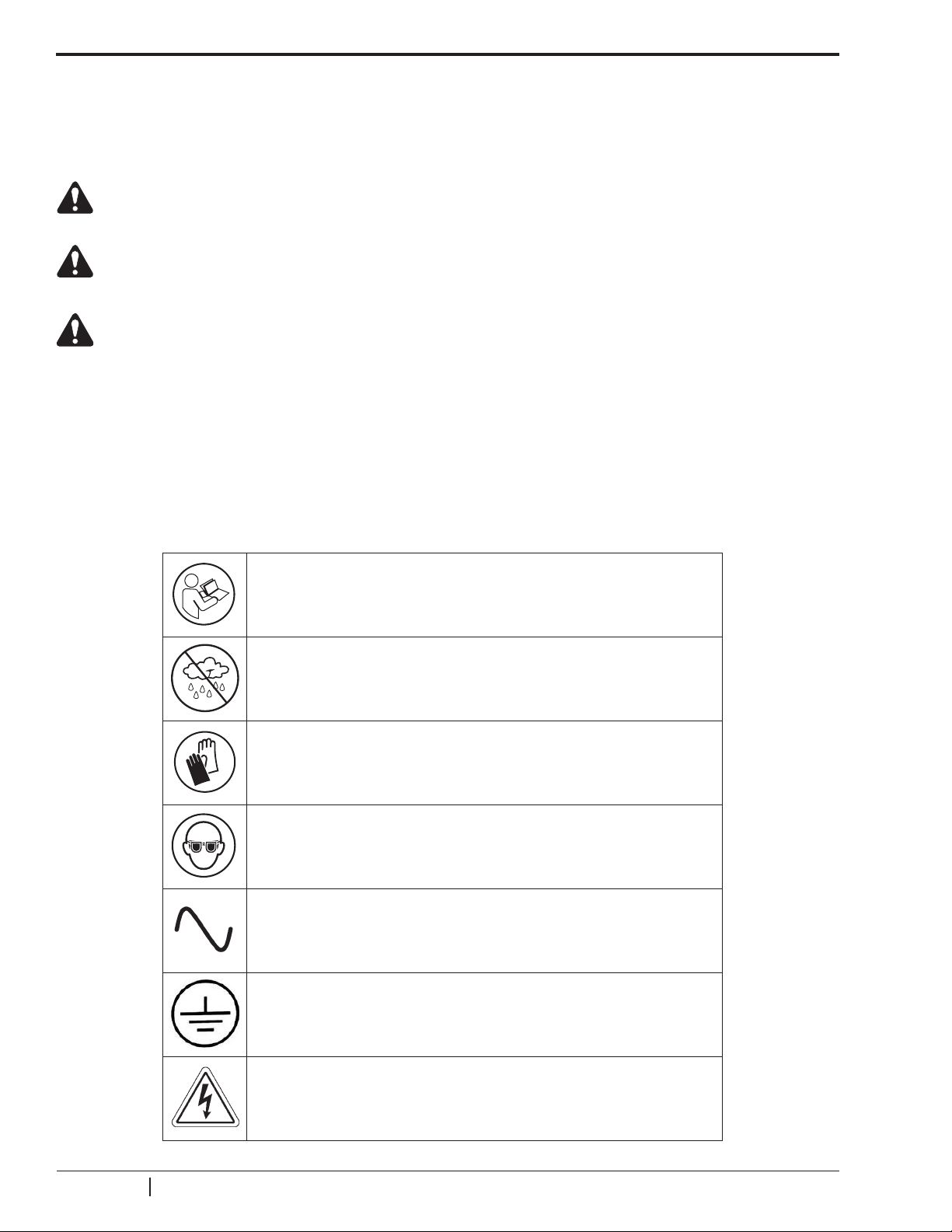
Explanation of Safety Decals Used on the Machine
Carefully read all instructions.
Do not use in open air in case of rain or high humidity.
Wear gloves.
Wear protection goggles.
Alternating voltage.
Grounding protection.
Electrical shock hazard.
SP00D00609 2018-03-26 Robert Bosch GmbH
4

ACS 753, ACS 763, ACS 863 Service Manual
WARNING: To prevent personal injury,
ALLOW ONLY QUALIFIED PERSONNEL TO OPERATE THE MACHINE. Before operating
the machine, read and follow all instructions and warnings in this manual. The operator must
be familiar with air conditioning and refrigeration systems, refrigerants, and the dangers of
pressurized components. If the operator cannot read this manual, all operating instructions
and safety precautions must be read and discussed in the operator’s native language.
USE THE MACHINE AS OUTLINED IN THIS MANUAL. Using the machine in a manner for
which it was not designed will compromise the machine and nullify the protections provided.
PRESSURIZED TANK CONTAINS LIQUID REFRIGERANT. Do not overll the internal
storage vessel (ISV), because overlling may cause explosion resulting in personal injury
or death. Do not recover refrigerants into a nonrellable container; use only type-approved
rellable containers that have a pressure relief valve.
HOSES MAY CONTAIN LIQUID REFRIGERANT UNDER PRESSURE. Contact with
refrigerant may cause personal injury, including blindness and frozen skin. Wear protective
equipment, including goggles and gloves. Disconnect hoses using extreme caution. Ensure
the phase has been completed before disconnecting the machine to prevent the release
of refrigeration to the atmosphere.
DO NOT BREATHE REFRIGERANT AND LUBRICANT VAPOR OR MIST. Refrigerant
reduces the oxygen available for breathing, resulting in drowsiness and dizziness. Exposure
to high concentrations of refrigerant causes asphyxiation, injury to the eyes, nose, throat,
and lungs, and can affect the central nervous system. Use the machine in locations with
mechanical ventilation that provides at least one air change per hour. If accidental system
discharge occurs, ventilate the work area before resuming service.
DO NOT DISPERSE THE REFRIGERANT INTO THE ENVIRONMENT. Such a precaution
is necessary to prevent the possible presence of refrigerant in the working environment.
The refrigerant R1234yf (ACS 763, ACS 863 only) is heavier than air and tends to
concentrate in the pits of the workshop.
TO REDUCE THE RISK OF FIRE, do not use the machine in the vicinity of spilled or open
containers of gasoline or other ammable substances.
TO REDUCE THE RISK OF FIRE, do not use an extension cord. An extension cord may
overheat and cause re. If you must use an extension cord, use the shortest possible cord
with a minimum size of 14 AWG.
TO REDUCE THE RISK OF FIRE, do not use the machine in the vicinity of ames and
hot surfaces. Refrigerant decomposes at high temperatures, freeing toxic substances to
the environment which are noxious to the user.
TO REDUCE THE RISK OF FIRE, do not use the machine in environments containing
explosive gases or vapors.
TO REDUCE THE RISK OF FIRE, Do not use this machine in ATEX classied zones
or areas. Protect the machine from conditions that may cause electrical failure or other
hazards relating to ambient interaction.
5
SP00D00609 2018-03-26Robert Bosch GmbH
ACS 753, ACS 763, ACS 863 Service Manual
DO NOT USE COMPRESSED AIR TO PRESSURE TEST OR LEAK TEST THE MACHINE
OR VEHICLE AIR CONDITIONING SYSTEM. Mixtures of air and refrigerant can be
combustible at elevated pressures. These mixtures are potentially dangerous and may
result in re or explosion causing personal injury and/or property damage.
HIGH VOLTAGE ELECTRICITY INSIDE THE MACHINE HAS A RISK OF ELECTRICAL
SHOCK. Exposure may cause personal injury. Disconnect the power before servicing the
machine.
NEVER LEAVE THE MACHINE LIVE IF AN IMMEDIATE USE IS NOT SCHEDULED.
Disconnect the electrical supply before a long period of inactivity or before internal
maintenance is performed. To ensure that unauthorized personnel cannot run the machine,
use the Lockout / Tag Out feature.
NOTE (R1234yf only): To minimize the risk of ignition, the unit software guided leak check is periodically performed otherwise the unit will lock. For same purpose, also hardware features such
as ventilation fan monitoring system, suitably located vents on cart bottom (R1234yf is heavier
than air) and sealed power switching circuits are present.
CAUTION:Themachineisnotintendedtooperatewithoilsclassiedasammable
or hazardous according to EN 1272/2008 (CLP).
CAUTION : To prevent equipment damage,
TO PREVENT CROSS-CONTAMINATION, USE THIS MACHINE WITH R1234yf
(ACS 763, ACS 863) OR R134a (ACS 753) REFRIGERANT ONLY. The machine is
equipped with special connectors to recover, recycle, and recharge only R1234yf (ACS 763,
ACS 863) or R134a (ACS 753) refrigerant. Do not attempt to adapt the machine for another
refrigerant. Do not mix refrigerant types through a system or in the same container; mixing
of refrigerants will cause severe damage to the machine and the vehicle air conditioning
system.
Do not use refrigerants other than those indicated on the technical data plate. It is also
recommended to buy it from specialized companies that guarantee its good quality.
DO NOT USE THIS MACHINE OUTDOORS DURING RAIN OR HIGH HUMIDITY. Protect
the machine from conditions that may cause electrical failure or other hazards relating to
ambient interaction.
DO NOT USE THIS MACHINE IN DIRECT SUNLIGHT. Position the machine far from heat
sources, such as direct sunlight which can cause excessive temperatures. The use of this
machine under normal environmental conditions (10°C to 50°C) keeps pressures under
reasonable limits. Make sure the machine does not exceed the operating temperature
indicated on the technical data plate.
DO NOT USE THIS MACHINE IN AREAS WHERE THERE IS A RISK OF EXPLOSION.
Place the station on a at surface and in sufcient lighting conditions; lock the front wheels
and do not subject them to vibration.
Further information regarding health and safety may be obtained from the refrigerant
manufacturer.
SP00D00609 2018-03-26 Robert Bosch GmbH
6

ACS 753, ACS 763, ACS 863 Service Manual
Protective devices
The machine is equipped with the following protective devices:
• Over pressure valves.
• A maximum pressure switch stops the compressor when excessive pressure is sensed.
WARNING: Tampering with these protective devices could result in serious injury.
WARNING: Do not modify the pressure relief valve or change the control system
settings. Using the machine in a manner for which it was not designed will compromise
the machine and nullify the protections provided.
CAUTION: Check always the pressure gauges values to ensure that pressures are
maintainedwithinthelimitsspeciedinthe“Unitspecications”section.
Door switch
Door switch on service rear door disconnects electrical power to the unit when opened.
WARNING: Do not tamper the interlock switch. During normal operation, the rear
service door must always be closed and the above panel in place.
Refrigerant Tank Test
Ofcial records and recurring tests necessary for pressurized instruments are governed by laws
and / or national regulations depending on the country where the refrigerant tank is used. The
system manager is responsible for respect of laws, regulations, and technical rules. During normal service, refrigerant tanks do not need maintenance. Refer to the Maintenance section of this
manual for more information.
Machine handling
The unit should normally be moved on at surfaces with a maximum slope of 15 ° and on the four
wheels, avoiding excessive shaking. When stopped then the brake on the front wheels must be
inserted. On slightly irregular surfaces, the unit can be moved by keeping it slightly inclined and
grounded on the two rear wheels by making sure to have a rm grip on the rear handle.
CAUTION: Although heavier components of the unit are installed on the bottom of
the unit in order to lower as much as possible the center of gravity, it’s however not
completely removed the risk of overturning.
7
SP00D00609 2018-03-26Robert Bosch GmbH

Introduct i o n
ACS 753, ACS 763, ACS 863 Service Manual
I n TroduCT I o n
Introduction .........................................................................................................9
Icon Legend ....................................................................................................................10
Glossary .......................................................................................................................... 11
Setup Menu ..................................................................................................................... 11
General Maintenance .....................................................................................................14
Electrical Protection ....................................................................................................... 14
Tank Fill ........................................................................................................................... 14
Filter Maintenance .......................................................................................................... 15
InternalRefrigerentIdentierMaintenance(ACS863only) ....................................... 16
Vacuum Pump Maintenance ..........................................................................................16
Edit Print Header ............................................................................................................17
Replace Printer Paper ....................................................................................................17
Calibration Check ........................................................................................................... 18
Scales Reset ...................................................................................................................18
Pressure Decay Leak Test (R1234yf only) .................................................................... 19
Lockout ............................................................................................................................19
UnitSpecications ............................................................................................ 20
Maintenance Schedule ......................................................................................22
Control Panel Functions ................................................................................................ 10
SP00D00609 2018-03-26 Robert Bosch GmbH
8
ACS 753, ACS 763, ACS 863 Service Manual
1 2 3
6
7
5
4
8
13
14
15
16
17
18
19
20
21
22
23
12
11
10
9
abc
def
jkl
mno
tuv
wxyz
ghi
pqrs
Introduct i o n
Introduction
These units are designed to be compatible with existing service equipment and standard service
procedures. These machines utilize a single-pass system that meets specications for recycled
refrigerant. Follow recommended service procedures for the containment of refrigerant.
Each unit includes a high-vacuum pump for fast, thorough evacuation. The compressor rst pulls
the A/C system to -0.4 bar; the compressor then works with the vacuum pump to pull a vacuum
to an absolute pressure of less than 1.0 bar.
NOTE: Refrigerant systems require special oils. Refer to the A/C system manufacturer’s service
manual for oil specications.
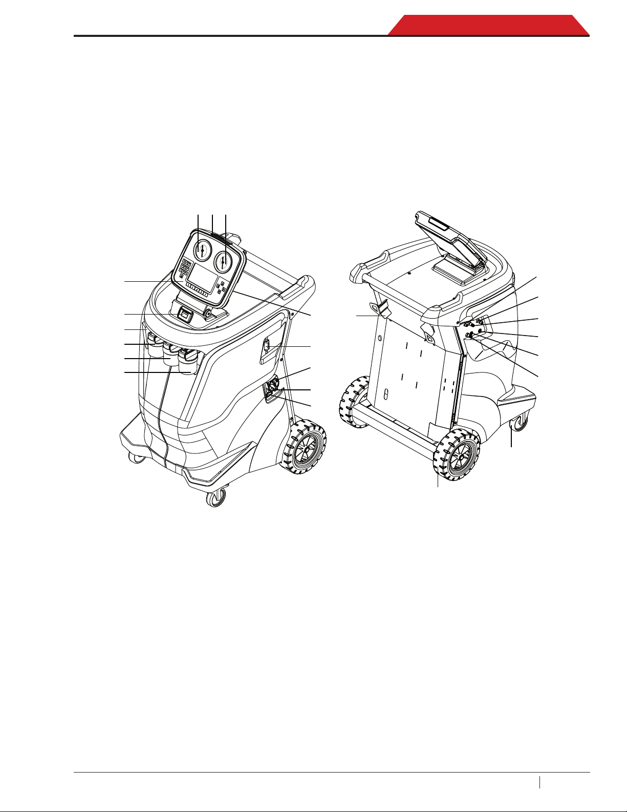
Figure 1-1. Description of machine
1. Gauge low pressure (LP)
2. Visual alert
3. Gauge high pressure (HP)
4. 2 x USB 2.0 slot
5. Identier Filter
(ACS 863 only)
6. Master switch
7. Circuit breaker
8. Power supply socket
9. UV dye bottle
10. Fresh oil bottle 2 (POE)
11. Fresh oil bottle 1 (PAG)
12. Used oil bottle
13. Printer
14. Display and control panel (HMI)
15. N2H2 or N2 inlet port max 14 bar (1.4 MPa)
16. Flush port (high pressure*)
17. Flush port (low pressure*)
18. Service hose port (high pressure*)
19. Service hose port (low pressure*)
20. Contaminant recovery outlet port
(ACS 863 only)
21. Front wheels with locking brake
22. Rear wheels
23. Hoses wraping support
(*) max 25 bar (2.5 MPa)
9
SP00D00609 2018-03-26Robert Bosch GmbH
Introduct i o n
Refrigerant
Main Menu
09:36
V 076.026.050
Standby
3.544 kg
7.34 bar
205 ml
POE
205 ml
PAG
205 ml
Dye
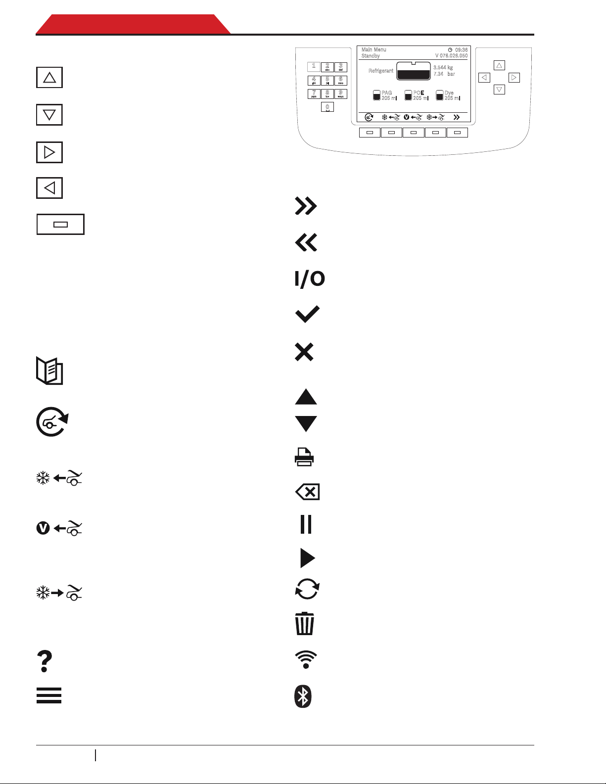
Control Panel Functions
ARROW UP moves selection of a
menu item to the previous item.
ARROW DOWN moves selection of
a menu item to the following item.
ARROW RIGHT scrolls to next
screen.
ARROW LEFT scrolls to previous
screen.
SELECTION KEYS (function keys)
to select the functions shown on
display (bottom icons).
ACS 753, ACS 763, ACS 863 Service Manual
Figure 1-2. Control Panel Keyboard
NEXT to move to the next screen
or step.
BACK to return to the previous
screen or step.
0...9
A...Z
The input keys can be used to
enter letters, numbers and special
characters in the input boxes.
Icon Legend
DATABASE supplies information
regarding charge capacity by vehicle
model.
AUTOMATIC activates a menu that
helps the user set up an automatic
recover / vacuum / leak test / charge
sequence.
RECOVER activates the sequence
to recover refrigerant from the vehicle
A/C system.
VACUUM activates the sequence
that pulls a deep vacuum on the
vehicle A/C system to remove air
and moisture.
ON/OFF to enable or disable the
selected function.
OK to confirm, proceed or save
settings.
ESC to cancel the operation and
return to the previous function or the
Main menu.
UP to move menu selection upward.
DOWN to move menu selection
downward.
PRINT to perform a print.
BACKSPACE to erase the character
to the left of the cursor.
PAUSE to pause a process.
PLAY to resume a paused process.
CHARGE activates the sequence
RETRY to repeat the last step.
that charges the vehicle A/C system
with a programmed amount of
refrigerant.
HELP displays information related to
the current display.
MENU accesses additional functions
and parameters.
SP00D00609 2018-03-26 Robert Bosch GmbH
10
DELETE to delete a selected entry
from the memory of the machine.
WIFI indicates that the WiFi
connection is enabled.
BLUETOOTH indicates that the
Bluetooth connection is enabled.

ACS 753, ACS 763, ACS 863 Service Manual
Introduct i o n
HS LS to set which side to charge
thru (high pressure, low pressure or
both sides).
ml oz to set the unit of measurement
(ml or oz).
kg oz lb to set the unit of measurement
(kg, oz or lb).
USB to export data onto a USB key.
Glossary
A/C System: The vehicle air conditioning
system being serviced.
Evacuation: Moisture and other incondensables
are removed from an A/C system by using a
vacuum pump.
Internal Storage Vessel (ISV): The tank
designed specifically for this machine has
refrigerant disposable capacity of 17.4 kg,
except the ACS 753 have a disposable capacity
of 19.4 kg.
Machine: Model No. ACS 753, ACS 763 or
ACS 863.
PAG/POE: Different oil types in the vehicle airconditioning system depending on the vehicle
manufacturer.
Recovery/Recycling: Refrigerant is recovered
from an A/C system, ltered, and stored in the
ISV.
Refrigerant: R134a (ACS 753) or R1234yf.
Source (or External Tank): A disposable tank
of new refrigerant used to rell the ISV; not
included.
Setup Menu
The machine launches into the initial Setup
mode (the rst time the machine is powered up).
NOTE: It is needed to complete all the setup
procedure sequence before to use the A/C unit.
Carry out the following setup:
1. Language selection.
2. License agreement review.
3. Units (Metric/Imperial) selection.
4. Date and Time adjustment.
5. Print Header Editor.
6. Identier setting (ACS 763 only).
7. Service Vacuum.
8. Internal Tank Fill.
At the end of the initial setup procedure it is
suggested to:
• Perform check scale.
• Perform air ow calibration.
Functions Menu
1. Call up the Main Menu.
2. Select NEXT icon.
3. Select MENU icon.
• Select Functions to access the following
functions.
A/C Perfomance Test
Performs a pressure test on an A/C system of
a vehicle with a refrigerant already present.
N2H2 or N2 Test
To search the leaks of the A/C system of a vehicle by means of an external bottle of Nitrogen
or a mixture of nitrogen and hidrogen.
Flush Hoses
Flushes residual oil from the machine to pre-
pare for the service of next vehicle.
System Flush
Provides a method of removing oil and impu-
rity by forcing liquid refrigerant through an A/C
system or components of an A/C system. After
ushing, the refrigerant is recovered by the
machine and ltered by the recycling circuit.
Tank Fill
Use this function to transfer refrigerant from a
source tank to the ISV. The tank ll value may
be adjusted up or down to suit the user’s needs.
Refer to Tank Fill in the Maintenance section.
11
SP00D00609 2018-03-26Robert Bosch GmbH

Introduct i o n
ACS 753, ACS 763, ACS 863 Service Manual
Periodic Leak Test
Performs double test (in vacuum and pressure)
to detect any leakage on the machine.
Refrigerant Tracking
Function to memorize the refrigerant amount
recovered and charged for every vehicle. The
display shows ve selection options:
√ Display: to show data of recovered and
charged refrigerant.
√ Export to USB: to extract the report with
recovered and charged refrigerant amount
in the vehicle. Data extraction via USB
stick, recommended size 2 GB and FAT
format (support is not part of scope delivery). Data are transferred as .csv le.
√ Erase all records: to erase all data stored
on the machine.
√ Print all records: to print all data stored
on the machine.
√ Disable Tracking: to disable the Refriger-
ant tracking function.
Oil Load Cells
To enable or disable the operation of fresh oil
PAG, fresh oil POE, used oil and UV dye scales.
RefrigerantIdentier(ACS763only)
To enable or disable the purity test of the
external refrigerant identier connected to the
USB port of the machine. The display shows
three selection options:
√ Alwaysdisplayidentierprompts: Dis-
plays the steps required to perform the
purity test.
√ Skip display identifier prompts: Not
displays the steps required to perform the
purity test.
√ Askusertoconnectidentier: Ask a
user, with a special message, to conrm
whether or not to perform the purity test.
Default Vacuum Leak Test Time
Program the machine to change duration of the
vacuum leak test time.
• Select BACK icon to return to the Setup
Menu.
Settings Menu
• Select Settings to access the following
functions.
Select Language
Select a language for screen prompts. English
is the default language.
Select Units
Program the machine to display metric or
imperial values. The default display is in a
metric system.
Date and Time
Program the machine for current date and time.
Edit Print Header
Programs information that will appear on the
printout each time a print function is used.
Unit Activation
Failure to register and activate the machine
within 30 days of initial startup will cause the
machine to lock out and not function. Select
this Settings Menu item and follow the prompts
before the trial period expires.
Set Buzzer
Program the machine to turn the buzzer on or
off.
Firmware Update
To upgrade the rmware through a USB stick
or via WiFi. The display shows three selection
options:
√ Check for Update: To check if new rm-
ware updates are available.
√ USB Update: To upgrade the firmware
through a USB stick.
√ Wi-Fi Update: To upgrade the rmware
through a WiFi network. If the unit is connected to WiFi network and the WiFi network is connected to Internet, it will automatically start searching for new updates.
SP00D00609 2018-03-26 Robert Bosch GmbH
12

ACS 753, ACS 763, ACS 863 Service Manual
Introduct i o n
WiFiConguration
To congure the WiFi connection to the machine. The display shows four selection options:
√ Search WiFi Networks: To search for
available WiFi networks.
√ WiFi status: To display some WiFi con-
nection data used.
√ Test WiFi connection: to perform a WiFi
network connection test used by the machine.
√ Disconnect current network: To disable
the WiFi network connection stored on the
machine.
Asanetwork
To enable or disable the asanetwork function.
For further information contact Customer Service.
Connected Repair [CoRe]
To enable or disable the CoRe function.
For more information see Connected Repair
[CoRe] chapter on the user manual.
• Select BACK icon to return to the Setup
Menu.
Maintenance Menu
• Select Maintenance to access the following functions.
Filter Maintenance
The lter removes acid, particulates, and moisture from the refrigerant. To meet requirements,
it is mandatory to replace the lter after (SEE
TABLE) of refrigerant has been ltered.
Pump Maintenance
Displays the amount of time remaining until
the next vacuum pump oil change is needed.
For maximum vacuum pump performance,
change vacuum pump oil every time the
lter is replaced. Refer to the Vacuum Pump
Maintenance in the Maintenance section.
ISV Purge Condition
Displays internal storage vessel (ISV) pressure
and temperature. It is used to eliminate
incondensables gas and helps to limit the
pressure in the ISV.
Calibration Check
Use to verify internal scale calibration. Refer to
Calibration Check in the Maintenance section
of this manual.
Adjust Zero Offset
To reset the fresh oil PAG, fresh oil POE, used
oil and UV dye scales.
Display Tittle Info
To activate or deactivate the pressure and
temperature values display of the machine.
System Information
Displays the revision level of the software in
the unit.
Service Menu
For service center use only.
Production Menu
For production use only.
• Select BACK icon to return to the Setup
Menu.
Model
R134a
Model
R1234yf
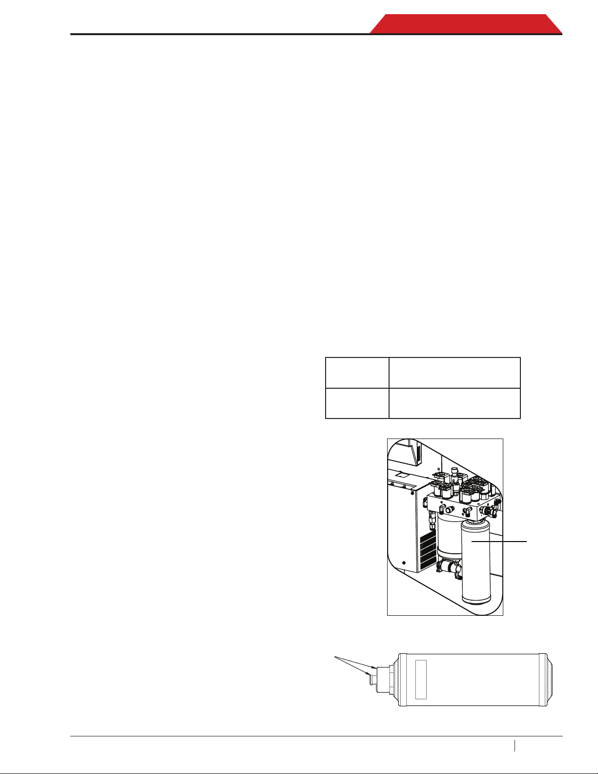
Replacement lter at: 68 kg
(alert 56 kg)
Replacement lter at: 150 kg
(alert 138 kg)
This menu item displays the lter capacity remaining until the machine locks down and no
longer functions. Refer to Filter Maintenance in
the Maintenance section.
13
SP00D00609 2018-03-26Robert Bosch GmbH
Introduct i o n
ACS 753, ACS 763, ACS 863 Service Manual
General Maintenance
Do not use abrasive cleaning agents, solvents
(petrol, diesel, etc.) and coarse workshop cloths
to clean the machine. Clean only using a soft
cloth and neutral cleaning agents.
NOTE: In cases of refrigerant leaks, such
as during installation, maintenance or repair
of machine, or even during normal use after
machine rest, there will be no refund by the
manufacturer.
CAUTION: Disconnect the power
supply before any maintenance.
Electrical Protection
The machine is equipped with a circuit breaker
to the side of the machine below the ON/OFF
switch. If the breaker trips, its button will pop
out. A tripped circuit breaker will cause the
machine to lose all power. Press the circuit
breaker button to reset. If the circuit breaker
does not reset or continues to trip, there is a
fault in the unit electrical system. Troubleshoot
and repair the affected component(s).
8. Select OK icon to start the tank ll process.
9. The machine (ACS 863 only) checks the
refrigerant in the source tank to verify it
is R1234yf and not contaminated. The
machine displays the following screens:
INITIALIZING REFRIGERANT IDENTIFIER
ANALYZING REFRIGERANT SAMPLE
REFRIGERANT PURITY PASSED
10. The machine begins filling the internal
storage vessel (ISV) and automatically
stops when the preset tank fill level is
reached. To stop the tank fill before the
preset level is reached, select PAUSE icon.
1
Tank Fill
This menu (available on Function menu) is
used to transfer refrigerant from a source tank
to the ISV.
1. Call up the Main Menu.
2. Select NEXT icon.
3. Select MENU icon.
4. Select TANK FILL from the Functions
Menu. The machine displays:
FILL AMOUNT: xx.xxyy
RECOVER CAPACITY: xx.xxyy
CHARGE CAPACITY: xx.xxyy
5. Enter the ll amount (at least 5 kg) to ensure
enough liquid refrigerant is available for
charging and select OK icon. Unit is set
with 2.2 kg dead space (rst 2.2 kg are not
shown on display anymore). If the source
tank is empty, or has insufcient refrigerant
for transfer, tank ll will stop.
6. Connect the low pressure service hose
(blue) to the liquid connector on a full source
tank.
7. Position the source tank in such a way
that liquid refrigerant is supplied to the
connection. Open the source tank valve.
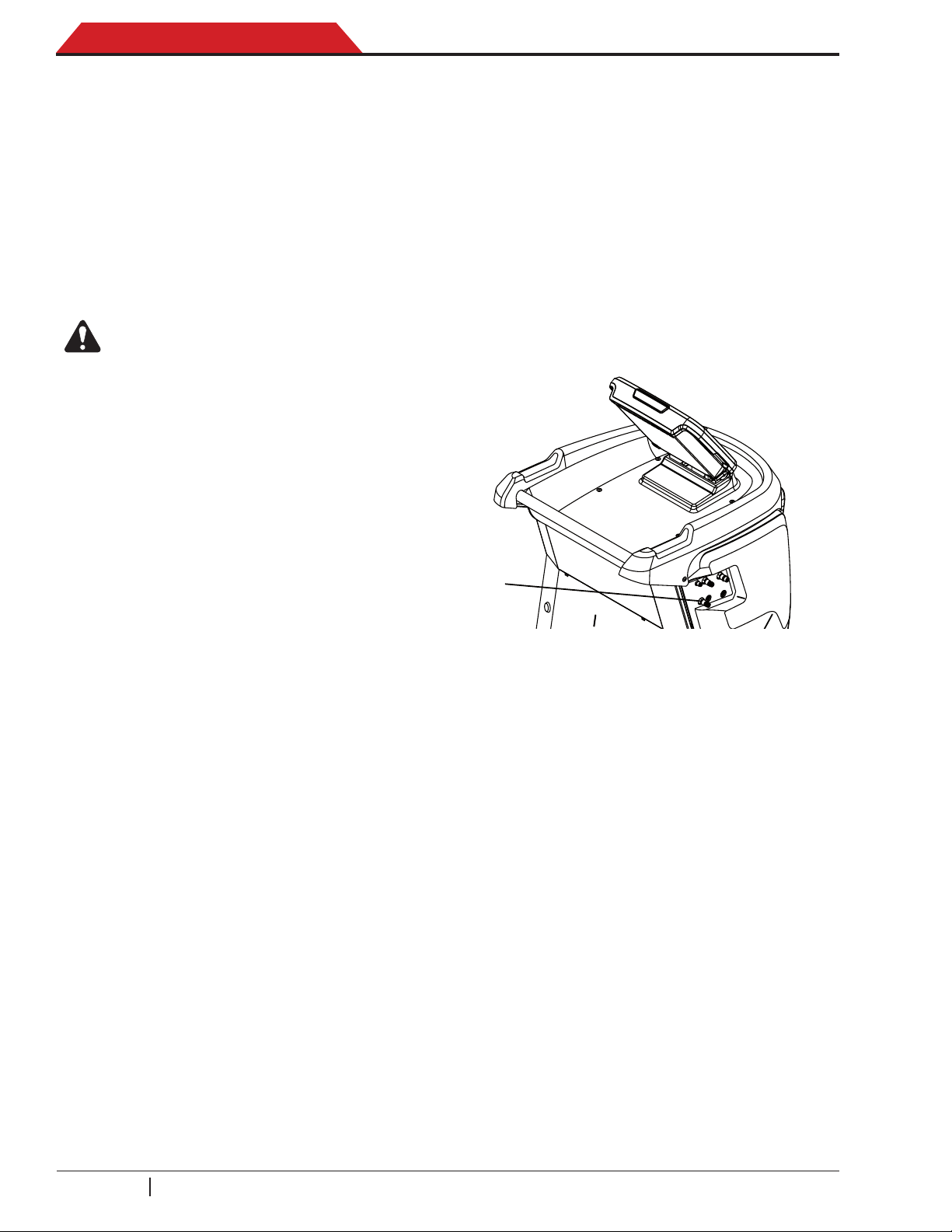
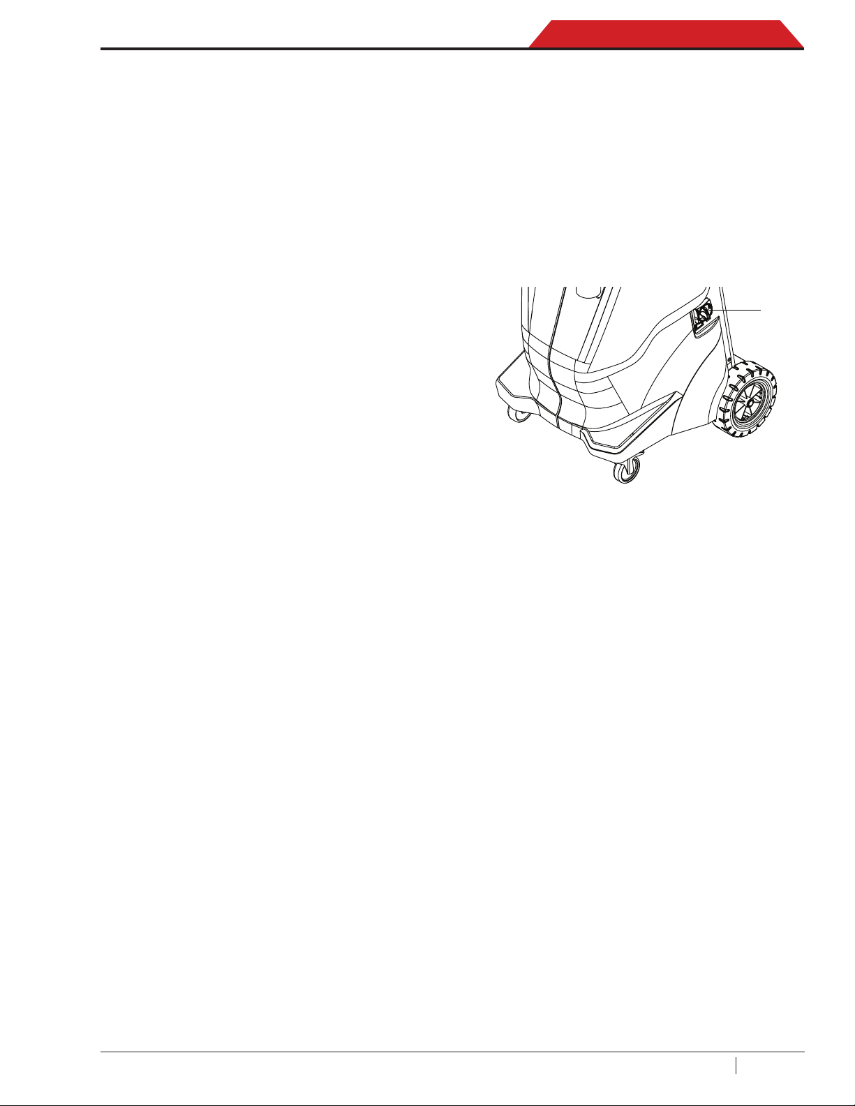
Figure 1-3. Contaminant recovery outlet port
11. Close the liquid valve and remove the hose
from the source tank.
12. Select OK icon to return to the Function
Menu.
Operating Tips (ACS 863 only)
1. If the machine displays
REPLACE IDENTIFIER FILTER
• the refrigerant identifier filter must be
replaced. Select OK icon to conrm, and
refer to the Refrigerant Identier chapter
of this manual for instructions.
2. If the machine displays
REFRIGERANT PURITY FAILED
RECOVER CONTAMINATED
REFRIGERANT FROM SYSTEM AND HOSES
• the refrigerant in the source tank is either
not R1234yf or it is contaminated. In either
case, it should not be added to the internal
storage vessel in the machine. The refrigerant purity is 95%.
SP00D00609 2018-03-26 Robert Bosch GmbH
14
ACS 753, ACS 763, ACS 863 Service Manual
Introduct i o n
• Connect a second recovery machine to
the tting (1) located on the side of the
machine. See Figure 1-3. Run a recovery
to remove the refrigerant sampled by the
refrigerant identier in the machine.
Filter Maintenance
The lter is designed to trap acid and particulates,
and to remove water from refrigerant. To meet
this mandate, the lter must be replaced after
(SEE TABLE) of refrigerant has been ltered.
The unit gives a warning when (SEE TABLE) of
the lter capacity has been used; the unit locks
(
down when the
been reached and will no longer function.
Check Remaining Filter Capacity
1. Call up the Main Menu.
2. Select NEXT icon.
3. Select MENU icon.
4. Select Filter Maintenance from the
Maintenance Menu or when the machine
prompts. The machine displays:
SEE TABLE) lter capacity has
3. Switch off the machine.
4. Open the service rear door.
5. Remove the old lter (1) by turning it clock-
wise. Refer to Figure 1-4.
6. Look at the new lter. Verify both O-rings
are lubricated and correctly located in the
grooves as shown in Figure 1-5.
7. Install the new lter by threading it counter-
clockwise into place. Verify the lter is positioned correctly. Tighten the lter to 20 Nm.
8. Close the service rear door.
9. Switch on the machine.
10. Machine starts with vacuum pump oil
change (Refer to the “Vacuum Pump Maintenance” in this section).
11. Recycle the lter that was removed from
the machine according to the laws in your
jurisdiction.
CAUTION:UseonlyauthenticBoschlters
in this machine. All performance tests and
claimsarebasedonusingthisspeciclter.
REMAINING FILTER CAPACITY: XXX.XYY
REPLACE FILTER NOW?
• The machine displays amount of lter ca-
pacity remaining until the machine locks
down. This message may occur at anytime
during the course of an A/C system main
tenance action.
5. Select OK icon to change the lter; Select
ESC icon to resume using the machine.
Replace the Filter
1. If OK icon was selected to change the lter,
the unit will clear the lter, then prompts for
the new lter code to be entered:
ENTER NEW FILTER SERIAL NUMBER
NOTE: If SERIAL NUMBER WRONG is
displayed, the serial number has been incorrectly
entered or the lter has already been used in this
machine.
2. Use the keypad to enter the serial number
that appears on the new lter and select OK
icon to continue.
• The machine clears the existing lter and
displays:
-
Model
R134a
Model
R1234yf
O-rings
Replacement lter at: 68 kg
(alert 56 kg)
Replacement lter at: 150 kg
(alert 138 kg)
1
Figure 1-4. Filter Location
TURN POWER OFF
AND REPLACE FILTER
15
Figure 1-5. O-ring Location
SP00D00609 2018-03-26Robert Bosch GmbH
Introduct i o n
ACS 753, ACS 763, ACS 863 Service Manual
InternalRefrigerentIdentier
Maintenance (ACS 863 only)
A refrigerant identifier samples refrigerant
going into the ISV to verify it is R1234yf and
not contaminated. Replace the sample hose
assembly during every lter change and also if
prompted by an error message saying the hose
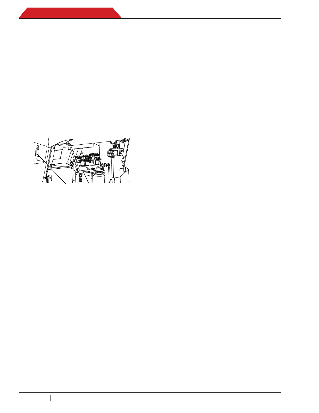
is clogged. See Figure 1-6.
1. Switch off the machine.
2. Open the service rear door.
3. Remove the rear cover (above the service
door) by pushing it up and extract it by pulling it out.
Vacuum Pump Maintenance
NOTE: Vacuum pump oil must be changed with
every lter change, every 100 hours pump runs
or more often as necessary.
1. Call up the Main Menu.
2. Select NEXT icon.
3. Select MENU icon.
4. Select Pump Maintenance from the
Maintenance Menu or when prompted. The
display shows how long the vacuum pump
has operated since the last oil change.
REMAINING OIL LIFE XXX:XX (hhh:mm)
CHANGE OIL NOW?
5. Select OK icon to change vacuum pump oil.
6. If the the machine displays:
WARMING OIL FOR DRAIN
• allow the vacuum pump to run for two
minutes to warm up the oil.
7. If the oil is already warm, the display shows:
1
Figure1-6.Internalrefrigerentidentierlocation
2
4. Disconnect the existing sample hose as-
sembly (2) between the rear side of the
manifold and the refrigerant identier, and
install a new sample hose assembly. If the
lter is any color but white, the lter must
be replaced.
5. Pull the lter barbs from the rubber hoses.
Snap the lter (1) out of the clip.
6. Install a new lter with the arrow pointing
downward as shown on the refrigerant iden-
tier. Do not kink the rubber hoses. Push
the rubber hoses back into the refrigerant
identier housing until they are straight.
7. Insert the rear cover so that the 4 holes on
the sides the cover t into the 4 clips on the
machine. Push down to hook the rear cover.
8. Close the service rear door.
DRAIN USED OIL FROM PUMP AND REPLACE
WITH 550 ML OF NEW OIL REMOVE CAP TO
SPEED DRAINING OF OIL
8. Switch off the machine.
9. Open the service rear door.
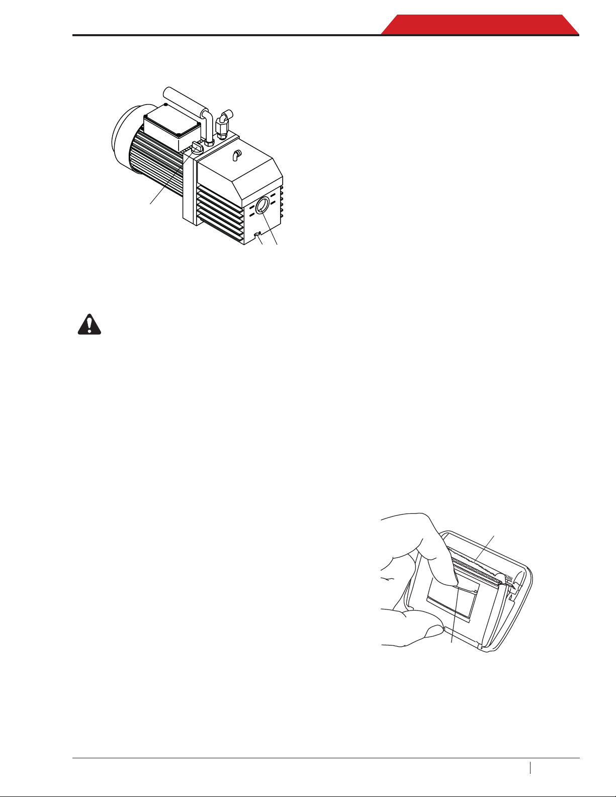
10. Slowly open the oil ll port cover (2) to verify
there is no pressure in the machine. Then
carefully remove the cover. See Figure 1-7.
11. Remove the oil drain tting cap (3) and drain
the oil into a suitable container for disposal.
Install the cap and close tightly.
12. Slowly add vacuum pump oil to the pump
through the oil ll port until the oil reaches
the center of the sight glass (1)
.
13. Install the cap on the oil ll port and close
tightly.
14. Close the service rear door.
15. Switch on the machine.
16. Select OK icon to continue.
17. The display show a message that indicate
to the user to check that the oil level is at
the center of the sight glass pump.
NOTE: In case it is necessary to add more oil,
repeat steps 8, 9, 10, 12, 13, 14 and 15 for
add oil.
SP00D00609 2018-03-26 Robert Bosch GmbH
16
ACS 753, ACS 763, ACS 863 Service Manual
1
3
Introduct i o n
18. Select ESC icon to return to the Maintenance Menu.
2
Figure 1-7. Oil Ports
CAUTION: To prevent personal injury,
do NOT operate the machine at any
other time without the oil ll port
cap installed, because the vacuum
pump is pressurized during normal
operation.
NOTE: Review the laws and regulations in your
jurisdiction to determine correct disposal procedures for pump oil. It is the responsibility of the
user to determine if a material is a hazardous
waste at the time of disposal. The user must
ensure compliance with all applicable laws and
regulations.
Edit Print Header
To make changes to the printer text (available
in Setting menu) appearing in the header on
each printout:
1. Call up the Main Menu.
2. Select NEXT icon.
3. Select MENU icon.
4. Select Edit Print Header in the Settings
Menu. The cursor is in the rst eld.
5. Update the text by using the arrows and the
multi-tap interface on the numeric keypad:
• BACKSPACE icon acts as a backspace
key.
• Right or left arrow moves the cursor to the
right or to the left.
• Zero (0) key also acts as a spacebar.
• Up and Down arrows navigate between
the rows.
6. Select OK icon to save the changes and
return to the Settings Menu.
7. Select ESC icon to exit and return to the
Settings Menu.
Replace Printer Paper
To install a new paper roll in the printer:
1. Remove the cover on the printer by pulling
out on the tab (2) as shown in Figure 1-8.
2. Remove the paper core.
3. Install the new roll of paper with the end of
the paper at the top of the roll.
4. Assemble the cover onto the printer with the
leading edge of the paper over the roller (1).
1
2
Figure 1-8. Replace Print Paper
17
SP00D00609 2018-03-26Robert Bosch GmbH
Introduct i o n
ACS 753, ACS 763, ACS 863 Service Manual
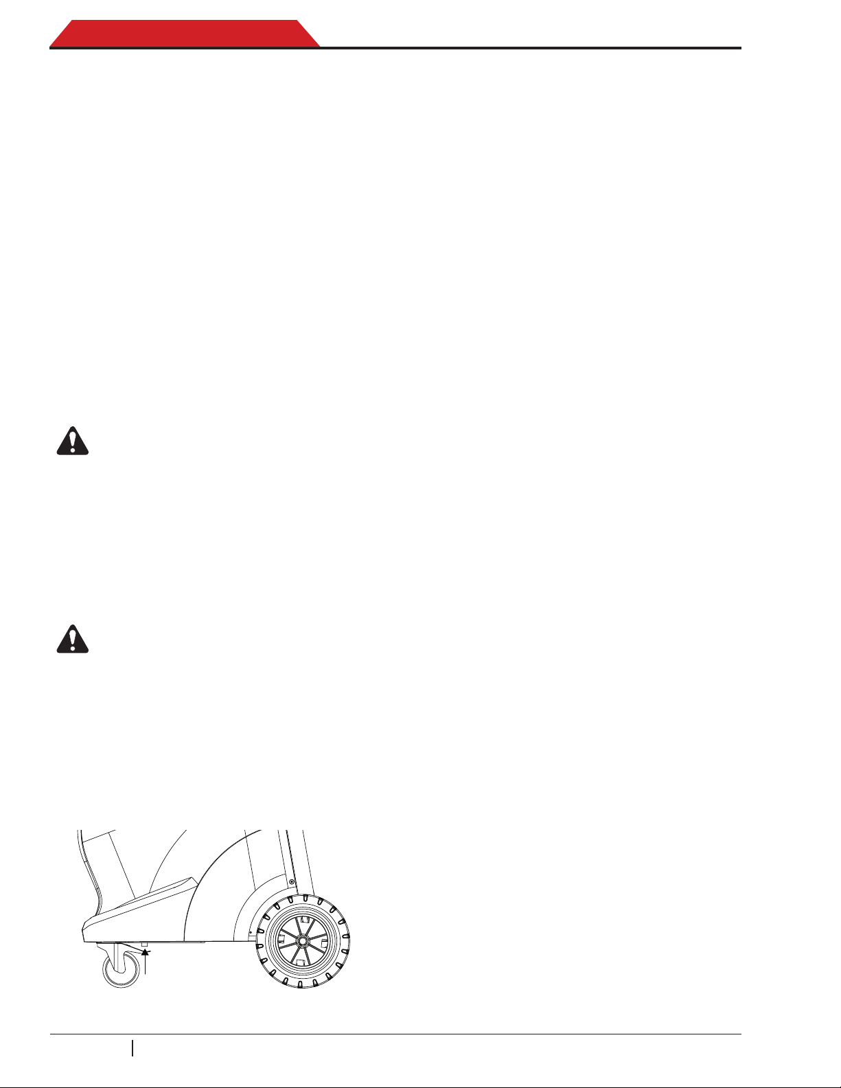
Calibration Check
This function is used to ensure the machine’s
internal scale is always calibrated. During this
test, use only the calibration weight provided
with the machine.
1. Verify the magnet on the bottom of the machine is clean. Refer to Figure 1-9.
2. Call up the Main Menu.
3. Select NEXT icon.
4. Select MENU icon.
5. Select Calibration Check from the Mainte-
nance Menu. The machine displays:
PLACE CALIBRATION WEIGHT ON MAGNET
LOCATED ON THE BOTTOM OF MACHINE
6. Attach the calibration weight to the magnet
(1) on the bottom of the machine.
7. Select OK icon to continue.
ALERT:Unitshown“Reading,donot
disturb”.
The machine displays:
REMOVE CALIBRATION WEIGHT
FROM MAGNET LOCATED ON THE BOTTOM
OF MACHINE
8. Remove calibration weight from magnet
located on the bottom of machine.
9. Select OK icon to continue.
Scales Reset
This procedure should be carried out regularly,
as the deviation from the zero point of the
oil/dye scales is corrected in the process.
1. Call up the Main Menu.
2. Select NEXT icon.
3. Select MENU icon.
4. Select Adjust Zero Offset from the Maintenance Menu.
5. Select the scale type to reset and conrm
with OK icon.
6. A message appears on the display to re-
move the oil bottles and/or the UV dye bottle
(according the selected scale type).
7. Carefully remove the bottle shown on the
display.
NOTE: To remove the “PAG”, “POE” and “UV
Dye” bottles, you must pull the lever on the
colored covers of the bottles slightly to unlock
and pull them outward. Instead to remove the
oil drain bottle it is enought pulling it straight
outwards.
8. Select OK icon to conrm and reset the
selected scale.
9. Repeat the same procedure to reset the
other scales.
10. Zero position of the 4 scales will be set.
ALERT: Do not touch the unit in this
phase!
• If the display shows Calibration passed
the scale is calibration. Select OK icon to
return to the Maintenance Menu.
• If the display shows Calibration failed the
scale is out of calibration. Select RETRY
icon to retry. If calibration continues to fail,
contact an authorized service center for
assistance.
1
Figure 1-9. Magnet Location
SP00D00609 2018-03-26 Robert Bosch GmbH
18
ACS 753, ACS 763, ACS 863 Service Manual
a
bc
d
ef
jkl
mno
tuv
wxyz
ghi
pq
r
s
Introduct i o n
Pressure Decay Leak Test
This function is available on Function menu.
To ensure a safe, environmentally friendly,
and economic operation, the unit performs a
software-controlled self-test in regular intervals
every 10 days (for R1234yf only).
1. Follow the on-screen prompts to connect
the hose service couplers to the storage
connectors on the side of the machine.
Open the hose couplers by turning the collars clockwise.
2. Select OK icon to start the test.
3. The machine performs a self-recovery and
displays:
RECOVER IN PROGRESS
4. The machine performs a 30-second vacuum
test and displays:
VACUUM CHECK IN PROGRESS
• If the vacuum test fails, the machine will
prompt to check for leaks.
5. Once the machine passes the vacuum test,
a controlled pressure is applied to its internal
components. The machine displays:
PRESSURE CHECK IN PROGRESS
Lockout
Never leave the machine live if an immediate
use is not scheduled. To ensure that unauthorized personnel cannot run the machine, use the
Lockout as shown in Figure 1-10.
1. Turn the Lockout lever (1) counterclockwise
(CCW).
2. Insert a padlock or other item through the
aligned holes so the lever cannot be turned
clockwise (CW) to start the machine.
1
Figure 1-10. Lockout
6. Pressure is held for ve minutes and moni-
tored for decay. Minutes and seconds count
down on the display.
• If an acceptable pressure decay is detected, the machine recovers refrigerant
and returns to the Functions Menu, ready
for normal operation.
• If an unacceptable pressure decay is detected, the machine will prompt to check for
leaks. Take the machine to an authorized
service center for repair.
NOTE: Leak Check may also be selected at
any time from the Functions Menu. If you decline to run the Leak Check when prompted,
the machine will continue to prompt for the test
at each power-up until the test is completed
(for R1234yf only).
19
SP00D00609 2018-03-26Robert Bosch GmbH
Introduct i o n
ACS 753, ACS 763, ACS 863 Service Manual
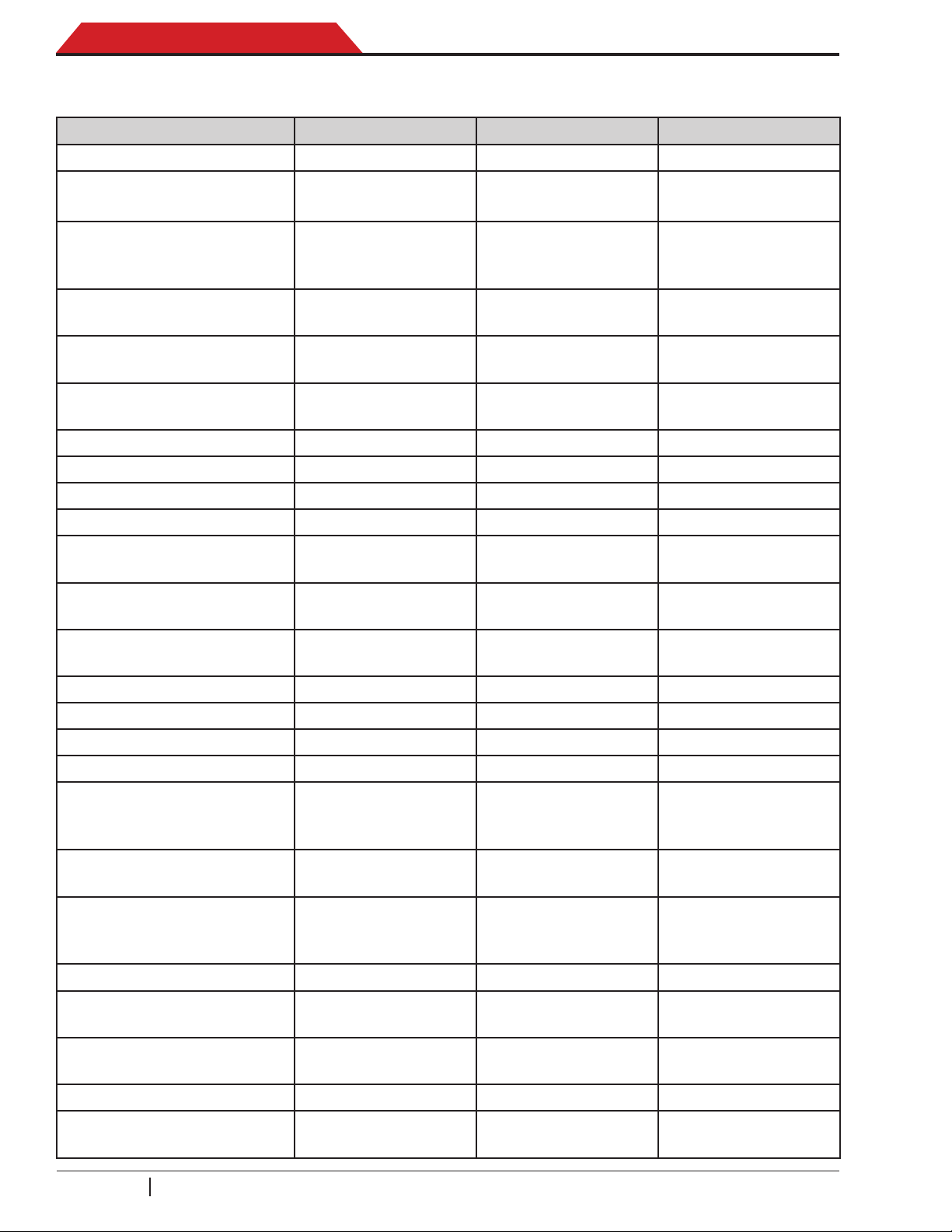
UNIT SPECIFICATIONS
ACS 763 ACS 863 ACS 753
Refrigerant R1234yf R1234yf R134a
ISV total capacity (water
capacity)
Internal Vessel Maximum
Storage Capacity (kg of
refrigerant)
Fluid Maximum Working
Pressure (PS)
Fluid Operating Tempera-
ture Range (TS)
Maximum Recovery Speed
(liquid phase)
Overall Leak Rate <80g/year <80g/year <80g/year
Power Supply 230 Vac/1 50/60 Hz 230 Vac/1 50/60 Hz 230 Vac/1 50/60 Hz
Overvoltage category II II II
Power Consumption 1100 W 1100 W 1100 W
Unit Storage Temperature
Range
Unit Operating Tempera-
ture Range
19.655 kg of R1234yf
(17.4 kg manageable
25 bar (2.5 Mpa) 25 bar (2.5 Mpa) 25 bar (2.5 Mpa)
-10 °C ÷ +120 °C -10 °C ÷ +120 °C -10 °C ÷ +120 °C
+10 °C ÷ +50 °C +10 °C ÷ +50 °C +10 °C ÷ +50 °C
22 l 22 l 22 l
19.655 kg of R1234yf
(17.4 kg manageable
by operator)
- - -
-20 °C ÷ +60 °C -20 °C ÷ +60 °C -20 °C ÷ +60 °C
by operator)
21.671 kg of R134a
(19.4 kg manageable
by operator)
Humidity (non-condensing) 32.2°C (90°F), 86%
RH
Maximum Altitude 2000 m (6561.66 ft) 2000 m (6561.66 ft) 2000 m (6561.66 ft)
IP Protection Rating IP20 IP20 IP20
Pollution dregree 2 2 2
Noise <70 dB(A) <70 dB(A) <70 dB(A)
Dimensions 105 x 75 x 77 cm
with HMI on shipping
position
Weight
(empty tank + accessories)
Display 7in. TFT WVGA
(800x480) color LCD
Filter 700 cc dessicant 700 cc dessicant 700 cc dessicant
Manometer Ø 100 mm
Bottles (Oils and Dye) 3 x 250 ml
112 kg 112 kg 112 kg
with LED backlight
EN 837-1 Class 1
sealed
32.2°C (90°F), 86%
RH
105 x 75 x 77 cm
with HMI on shipping
position
7in. TFT WVGA
(800x480) color LCD
with LED backlight
Ø 100 mm
EN 837-1 Class 1
3 x 250 ml
sealed
3°C (90°F), 86% RH
105 x 75 x 77 cm
with HMI on shipping
position
7in. TFT WVGA
(800x480) color LCD
with LED backlight
Ø 100 mm
EN 837-1 Class 1
3 x 250 ml
sealed
Service hoses 250 cm / SAE J2888 250 cm / SAE J2888 250 cm / SAE J639
Quick Couplers For R1234yf,
SAE J2888
SP00D00609 2018-03-26 Robert Bosch GmbH
20
For R1234yf,
SAE J2888
For R134a,
SAE J639
ACS 753, ACS 763, ACS 863 Service Manual
ACS 763 ACS 863 ACS 753
Flush Port Yes Yes Ye s
Introduct i o n
RefrigerantIdentier Optional as external
device
Flush Kit Optional for R1234yf Optional for R1234yf Optional for R134a
N2H2 Yes, embedded port
for external tank
Wireless Wi/BT usb dongle
into scope of delivery
External source cylinder
adapters
1234YF LS J639
MALE TO
W21.8-1/14LH
ADAPTER
ADAPTER 1234YF
LS J639 MALE
M26.2x1.8
ADAPTER 1234YF
LS J639 MALE
12.7 mm ACME16
Compressor
Power 1/4 HP 1/4 HP 1/4 HP
Displacement 8.85 cm
3
Embedded -
Yes, embedded port
for external tank
Wi/BT usb dongle
into scope of delivery
1234YF LS J639
MALE TO
W21.8-1/14LH
ADAPTER
ADAPTER 1234YF
LS J639 MALE
M26.2x1.8
ADAPTER 1234YF
LS J639 MALE
12.7 mm ACME16
8.85 cm
3
Yes, embedded port
for external tank
Wi/BT usb dongle
into scope of delivery
QUICK COUPLER
FOR COMMERCIAL
TANK 1/4” SAE
TANK ADAPTER
R134a - 21,8-14
G/1/4
8.85 cm
3
Recovery performance
- - -
(maximum, liquid phase)
Power Supply 230 Vac/1 50/60 Hz 230 Vac/1 50/60 Hz 230 Vac/1 50/60 Hz
Vacuum Pump
Free Air Displacement 170 l/min (6 CFM) 170 l/min (6 CFM) 170 l/min (6 CFM)
Ultimate Vacuum (min) 40 microns 40 microns 40 microns
Oil Capacity 700 ml 700 ml 700 ml
Type 2 stages oil bath 2 stages oil bath 2 stages oil bath
Power Supply 230 Vac/1 50/60 Hz 230 Vac/1 50/60 Hz 230 Vac/1 50/60 Hz
Scales
ISV scale accuracy ±15 g ±15 g ±15 g
Bottle scales accuracy ±2 g ±2 g ±2 g
21
SP00D00609 2018-03-26Robert Bosch GmbH
Introduct i o n
ACS 753, ACS 763, ACS 863 Service Manual
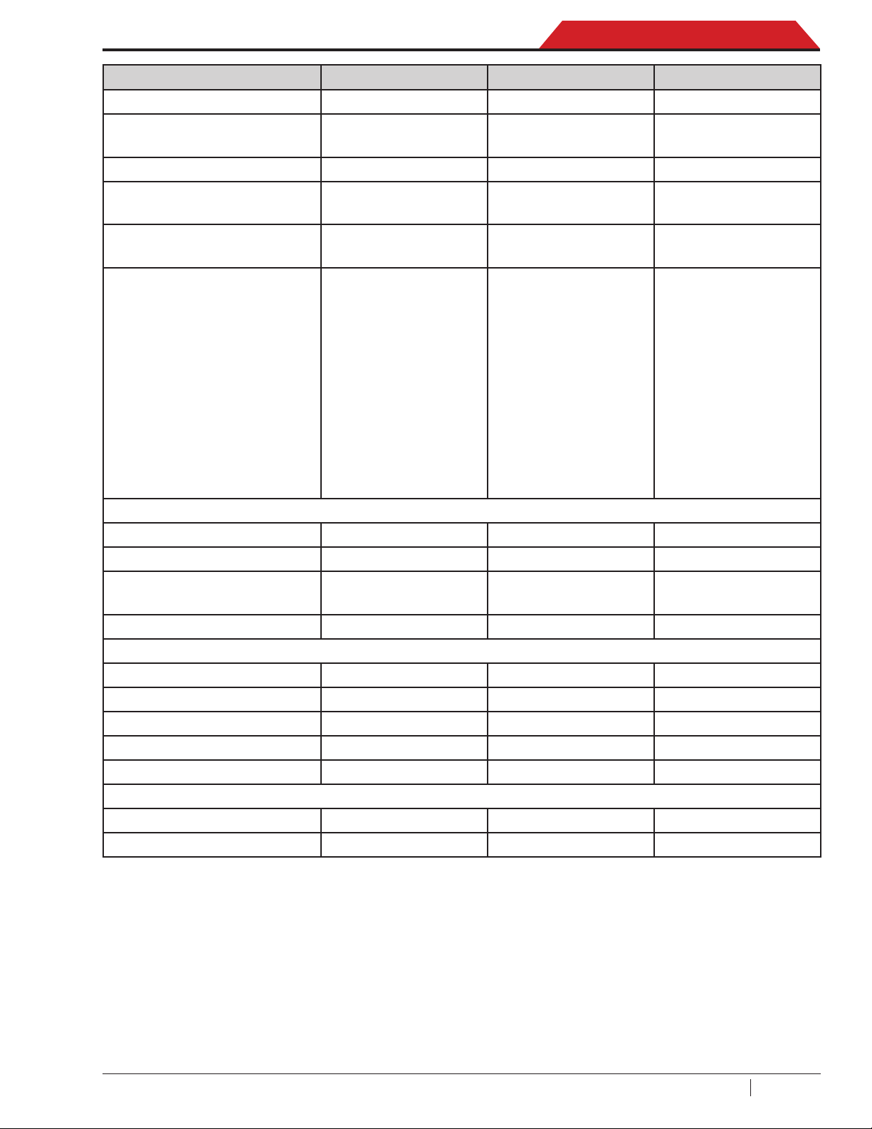
MAINTENANCE SCHEDULE
MAINTENANCE TASK RECOMMENDED INTERVAL
After (SEE TABLE) of refrigerant has
been ltered. Refer to Filter Change in the
Maintenance section of this manual.
Changelter
Change vacuum pump oil
Check casters and wheels for ease of
operation
Check internal scale calibration
Reset of PAG and POE Injection Oil, drain
oil and UV dye scales
Check machine for leaks
Model
R134a
Model
R1234yf
Replacement lter at:
68 kg (alert 56 kg)
Replacement lter at:
150 kg (alert 138 kg)
When the lter is replaced or every 100 hours.
Refer to Change Vacuum Pump Oil in the
Maintenance section of this manual.
Monthly.
Monthly. Refer to Calibration Check in the
Maintenance section of this manual. Every year
all scales must be calibrated by an authorized
service center.
Whenever it is necessary. Refer to Scales Reset
in the Maintenance section of this manual.
Automatic every 10 days (for R1234yf) or every
yearly (for R134a). Refer to Pressure Decay
Leak Test in the Maintenance section of this
manual.
Clean air intake panels Monthly. Use a clean cloth.
Clean cabinet and control panel Monthly. Use a clean cloth.
Inspect power cord and hoses for cuts
and abrasions
Lubricate wheel bearings and brake
components
Solenoid valves inspection
Checktheinternalrefrigerantidentier
lter(ACS863only)
Daily.
Monthly.
Every yearly — performed by an authorized
service center.
Daily.
Every six months or whenever it is dirty and / or
Changelterandsamplehoseofthe
internalrefrigerantidentier(ACS863
only)
clogged. Replace the sample hose assembly
during every lter change. Refer to Refrigerant
Identier Maintenance in the Maintenance
section of this manual.
Due to normal wear and tear, these units require regular maintenance to ensure safe operation
and optimum performance. The above chart provides a schedule of the minimum recommended
maintenance tasks.
SP00D00609 2018-03-26 Robert Bosch GmbH
22

ACS 753, ACS 763, ACS 863 Service Manual
Diagnostics and Testing
d I a g n o s T I C s and TesTIng
Functional Check ..................................................................................................24
Updating System Software Instruction ............................................................................24
Recover Function ...............................................................................................................25
Charge Function ................................................................................................................. 26
Diagnostics and Testing ....................................................................................... 28
Service Center Menu .......................................................................................................... 28
Diagnostics and Troubleshooting .....................................................................................28
Calibrate Load Cells ........................................................................................................... 28
Output Test .......................................................................................................................... 32
Input Test ............................................................................................................................. 33
Calibrateairow .................................................................................................................33
A/C unit Internal Clearing ..................................................................................................34
Service Vacuum ..................................................................................................................34
End User Install ..................................................................................................................35
Maintenance Counters ....................................................................................................... 35
Keypad Test ........................................................................................................................ 37
Set Serial Number ...............................................................................................................37
Set Manufacturing Date .....................................................................................................37
Set Boot Mode ....................................................................................................................38
Reset Board ........................................................................................................................38
RefrigerantIdentier(ACS863only) ................................................................................ 39
Charge Leak Test ................................................................................................................ 39
10 Days Leak Test (R1234yf only) ..................................................................................... 39
Default Vacuum Time ......................................................................................................... 39
Default Vacuum Leak Test Time ........................................................................................39
Default Precharge Leak Test Time .................................................................................... 39
Service hose length ............................................................................................................39
Depressurizing the Unit ........................................................................................ 40
Unit is Functional ...............................................................................................................40
Unit is Not Functional ........................................................................................................40
Troubleshooting ....................................................................................................41
Grounding, Noise, and Power Issues ...............................................................................41
Will Not Power-Up, No Display .......................................................................................... 42
Will Not Fill Tank ................................................................................................................. 43
Stuck In Clearing ................................................................................................................43
Will Not Recover ................................................................................................................. 44
Will Not Deep Recover .......................................................................................................45
Will Not Drain Oil ................................................................................................................46
Will Not Air Purge ...............................................................................................................46
Will Not Evacuate (Vacuum) ..............................................................................................47
Fails Leak Test .................................................................................................................... 48
Will Not Inject Oil or Dye .................................................................................................... 48
Will Not Charge ................................................................................................................... 49
Slow Charge ........................................................................................................................ 49
Will Not Hose Flush ............................................................................................................ 49
Will Not Print ....................................................................................................................... 50
Power Board Troubleshooting ..........................................................................................51
Control Board Troubleshooting ........................................................................................51
Compressor Troubleshooting ...........................................................................................52
Vacuum Pump Troubleshooting ........................................................................................53
Error Messages .....................................................................................................54
23
SP00D00609 2018-03-26Robert Bosch GmbH

Diagnostics and Testing
FUNCTIONAL CHECK
ACS 753, ACS 763, ACS 863 Service Manual
Prior to performing a functional or diagnostic
check, make sure the software version is
current. This is especially true if the control
and/or power boards have been replaced. If
the software version is not current, corrupt,
or unknown, follow the procedure in Updating
System Software Instruction.
Updating System Software Instruction
To upgrade the rmware through a USB stick
or via WiFi (see Firmware update in the Setup
Menu function section).
Download and install current Software
with USB stick
Equipment Requirements:
(1) USB stick
This item may be purchased from most retail
office supply/electronics stores or from any
online retailer that carries computer accessories.
In case of Firmware update with USB stick
follow the instruction:
1. Insert the USB stick to your computer.
2. Format as FAT32.
3. Download the current software from:
\EDIS\software\systemsw\acs6xx_7xx\.
4. Put the zip package as is into the root folder
of the USB stick.
5. Insert the USB stick into the USB port on
the unit.
6. Turn ON the unit.
7. Call up the Main Menu.
8. Select NEXT icon.
9. Select MENU icon.
10. Select Settings
USB Update.
11. Allow the unit to install the software completely and then remove the USB stick, this
operation may requires several minutes.
12. Wait the screen that ask to reboot the unit at
the end of the update process and so recyle
the unit power.
13. When the unit reboot conrm the installation
procedure by press <Yes> button when the
bootloader black and white screen is shown.
" Firmware update and
14. The unit will go through a le updating pe-
riod (it can take several minutes) to nalize
the entire update procedure, then will display the Main Menu.
Install Current Software with WiFi
Once WiFi connection has been established
select Wi-Fi Update (Call up the Main Menu and
select Next " Menu " Settings " Firmware
update " Wi-Fi Update)
.
1. Manual path:
Select Wi-Fi Update and check the new
software availability then select HELP
icon to look into release note or OK icon
to start the update procedure that is
composed by the following steps:
• Downloading compressed software package.
• Decrypt the software package and validate it to be sure that is a not corrupted.
• Decompress the content.
• Install all new les.
• Request user to reboot unit and complete
the install procedure.
• When the unit reboot conrm the installation procedure by press <Yes> button
when the bootloader black and white
screen is shown.
• The unit will go through a le updating
period (it can take several minutes) to
nalize the entire update procedure, then
will display the Main Menu.
2. Automatic path:
After the connection to internet network is
available, when the ACS unit is switched
on, it’s automatically connect to the same
network and immediately (before to show
the Main Menu) it will search for new software is available of not, if yes it will show
a message to process as above (point 1).
SP00D00609 2018-03-26 Robert Bosch GmbH
24
ACS 753, ACS 763, ACS 863 Service Manual
Diagnostics and Testing
NOTE: Refer to Scale Calibration at
Replacement Scale Assembly/Magnet in the
Electrical section, if necessary.
The Recover and Charge function tests must be
performed sequentially, in the order presented
here.
Recover Function
During the Recover process, the system will
initiate a lter check, service data entry, and
inlet pressure check.
1. Empty the oil drain bottle before starting a
recovery.
2. Connect the high-side (red) and/or low-side
(blue) hoses to the test tank.
3. Open the coupler valves on the hoses by
turning the collars clockwise.
4. Select the RECOVER icon from the main
menu.
5. The screen will message display: “Connect
both service hoses to AC system being
serviced and open both coupler valves”.
6. Select OK icon and unit perform:
• inlet pressure check.
• A/C unit internal clearing process.
• 1st recovery stage.
• 2 st recovery stage (deep recover).
7. Select OK icon to continue or ESC icon to
cancel.
11. 2th stage recovery. Unit perform special
deep recovery function where pump and
compressor are working togheter to intake all
refrigerant small parts still in the A/C vehicle
system. Deep recover min tiem is 5 minutes.
Then Oil drain process to evacuate the
accumulator from used oil recoverd by vehicle.
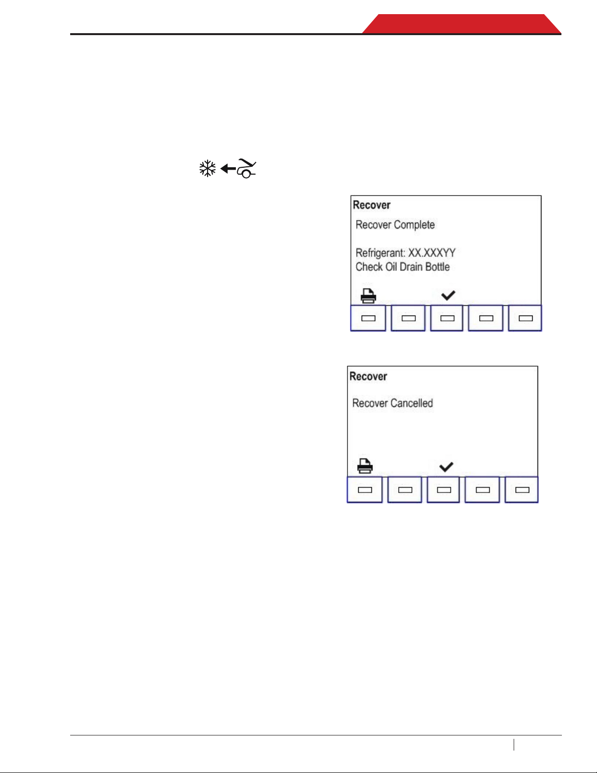
12. After the oil drain is complete, a summary
of the amount of refrigerant recovered and
oil drained is displayed. The unit displays:
Or:
8. The machine (ACS 863 only) checks the
refrigerant in the source tank to verify it
is R1234yf and not contaminated. The
machine displays the following screens:
INITIALIZING REFRIGERANT IDENTIFIER
ANALYZING REFRIGERANT SAMPLE
REFRIGERANT PURITY PASSED
9. The unit will run low-side clearing then enter
st
into a 1
stage Recovery.
10. When the system has recovered to
-0.4 bar, the vacuum pump starts and runs
until recover is complete.
13. Select Print icon to print out recovery
information and pre-recover diagnostics or
select OK icon to return the main menu.
The displayed recovered weight can vary
depending on ambient conditions and
should not be used as an indicator of
scale accuracy. The amount of oil that was
removed from the A/C system is the amount
of new oil that can be charged into the A/C
system after evacuation is complete.
• Use only new oil to replace the oil removed
during the recycling process.
• Dispose of used oil according to government
laws and regulations.
Recovery is complete.
25
SP00D00609 2018-03-26Robert Bosch GmbH
Diagnostics and Testing
ACS 753, ACS 763, ACS 863 Service Manual
Charge Function
Automatic leak tests will be performed during
the charge function. To avoid false failures,
the temperature of the vehicle system and the
temperature of the recovery machine should be
within ±5 degrees °C of each other.
1. Connect (or verify) both service hoses to
the test tank and turn the quick couplers
clockwise.
2. Select the CHARGE icon from the main
menu. Unit show the ENTER VEHICLE
DATA input page, confirm with OK icon.
The following display may show:
Machine is asking to input:
• Oil inject (Yes or No). If select No unit
don’t inject any oil (neither the recovered
one).
• Oil amount: xxx ml (is possible set as ml,
oz or lb).
• Oil type: 2 option (PAG or POE).
• Dye inject amount: xxx ml (is possible set
as ml, oz or lb).
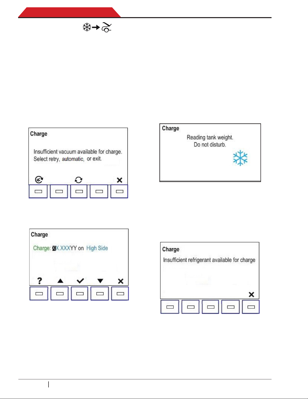
4. Conrm with OK icon and begin the charge
process. Moving or bumping the unit at this
point may result in an inaccurate charge.
Charging please wait displays:
If there is sufficient vacuum available, this
displays:
Machine is asking to input:
• Charge amount (min is 10 g).
• Select charge hoses (3 option: High, Low
and Both side).
3. Select OK icon to continue.
5. When the charge cycle gets close to the
desired weight value, the machine slows
down. It will charge, settle, charge again,
settle, etc.
6. If there is not sufcient refrigerant in the tank
to charge the system, the display shows:
7. Select ESC icon to exit. May require tank ll.
SP00D00609 2018-03-26 Robert Bosch GmbH
26
ACS 753, ACS 763, ACS 863 Service Manual
Diagnostics and Testing
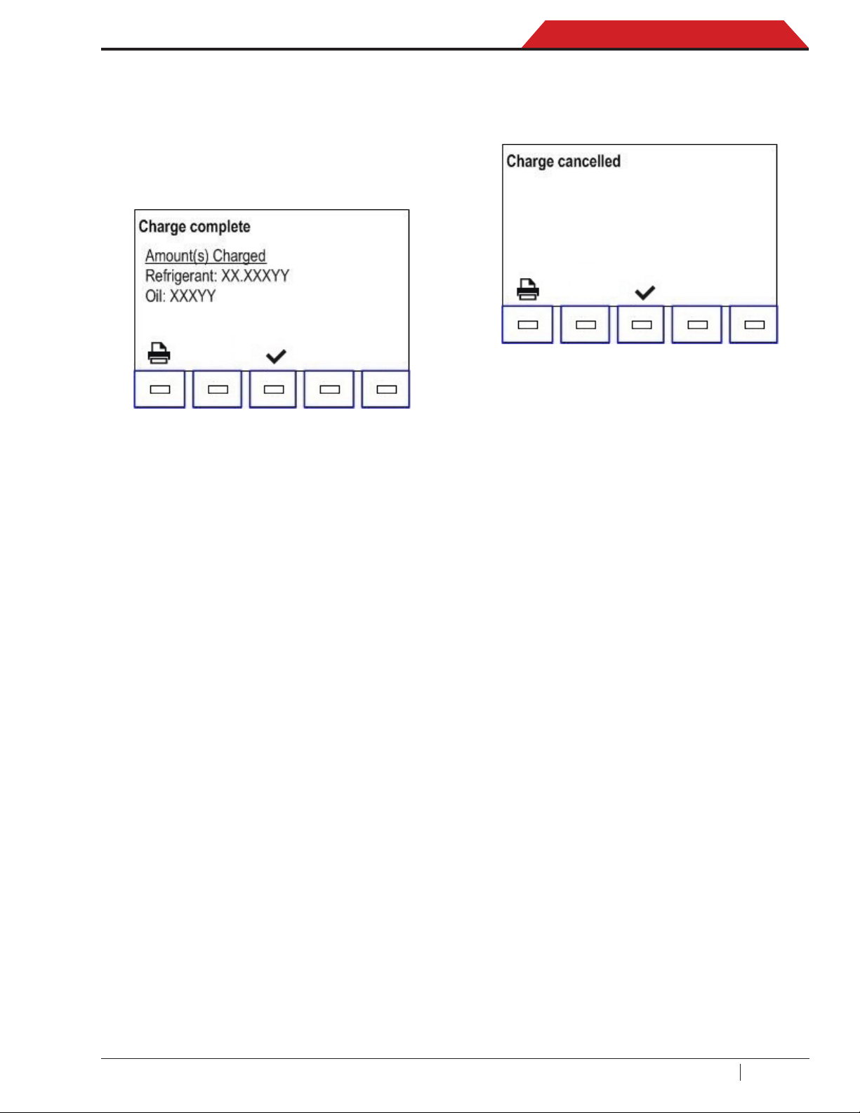
8. If the amount of refrigerant is sufficient
to charge the system to completion, the
display will show hoses compendation a
few seconds and then close coupler valves
and disconenct service hoses from vehicle.
The charge is complete:
9. Select OK icon then the unit will begin a
hose clearing process to remove refrigerant
from the hoses, followed by a short recovery.
10. At the end unit show the charged data and
print out option.
11. If the charge was cancelled, Charge
complete will change to Charge cancelled
and the values on the display will disappear:
12. Select OK icon to exit.
13. The unit will begin a hose clearing process
to remove refrigerant from the hoses,
followed by a short recovery.
Charge is complete.
27
SP00D00609 2018-03-26Robert Bosch GmbH
Diagnostics and Testing
ACS 753, ACS 763, ACS 863 Service Manual
DIAGNOSTICS AND TESTING
NOTE: These are the Service Options at the time of printing this service manual. Some options
may be added or deleted in future circuit board and software updates and revisions.
WARNING: Never change the default settings unless directed by the factory.
Otherwise the unit may fail to operate properly.
WARNING: Never give the programming or service codes to customers.
Service Center Menu
NOTE: Consult the Technical Service Bulletins
for the latest software version as applicable. To
navigate through the Service Menu, use the
keypad and arrow keys.
Diagnostics and Troubleshooting
1. Turn unit on and allow it to run through the
boot sequence.
2. Select NEXT icon.
3. Select MENU icon.
4. Select MAINTENANCE.
5. From the maintenance menu, scroll up and
nd SERVICE MENU.
6. Enter yearly password then select OK icon.
The following displays:
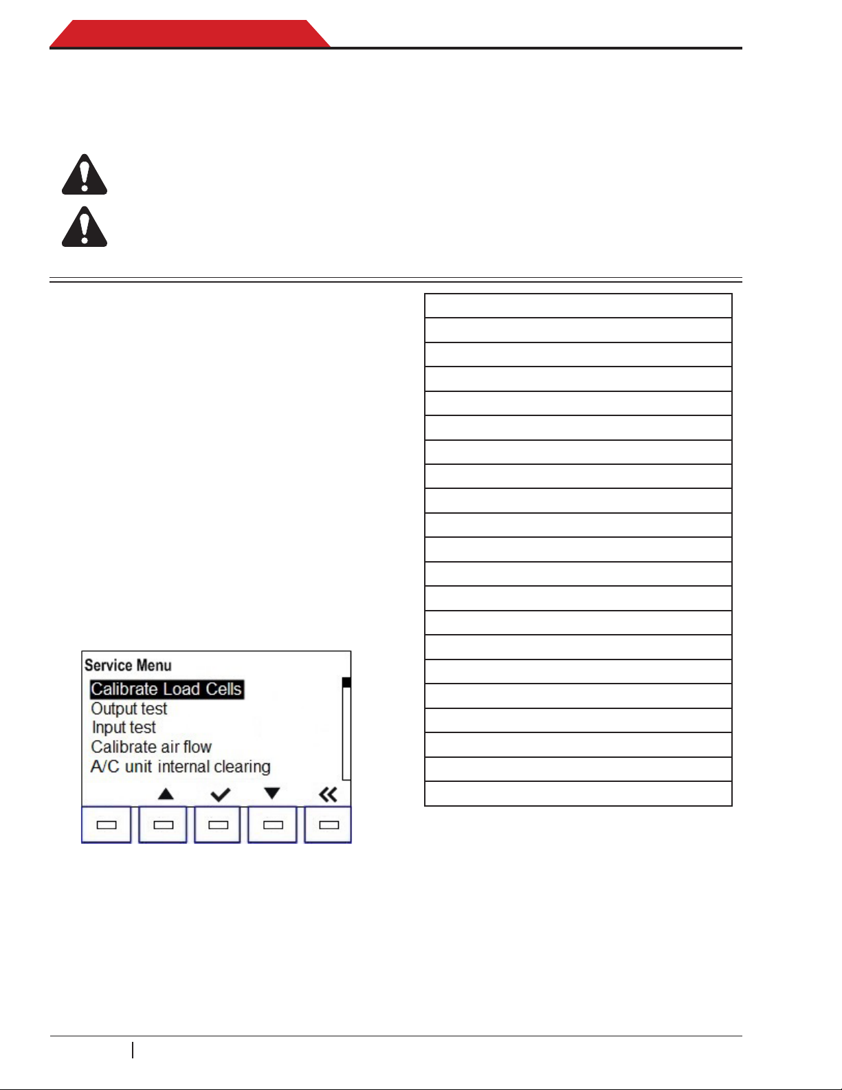
Service Menu
• Calibrate Load cell
• Output test
• Input Test
• Calibrate air ow
• A/C unit internal clearing
• Service vacuum
• End user install
• Maintenance counters
• Keypad test
• Set serial number
• Set Manufacturing date
• Set boot mode
• Reset Board
• Refrigerant identier
• Charge leak test
• 10 days leak test
• Default vacuum time
• Default vacuum leak test time
• Default precharge leak test time
• Service hose length
Calibrate load cell
• To perform any of the checks in the Service
Menu, use the up and down arrows to scroll
to the desired test listed and select OK icon.
• To exit the Service Menu, select BACK icon.
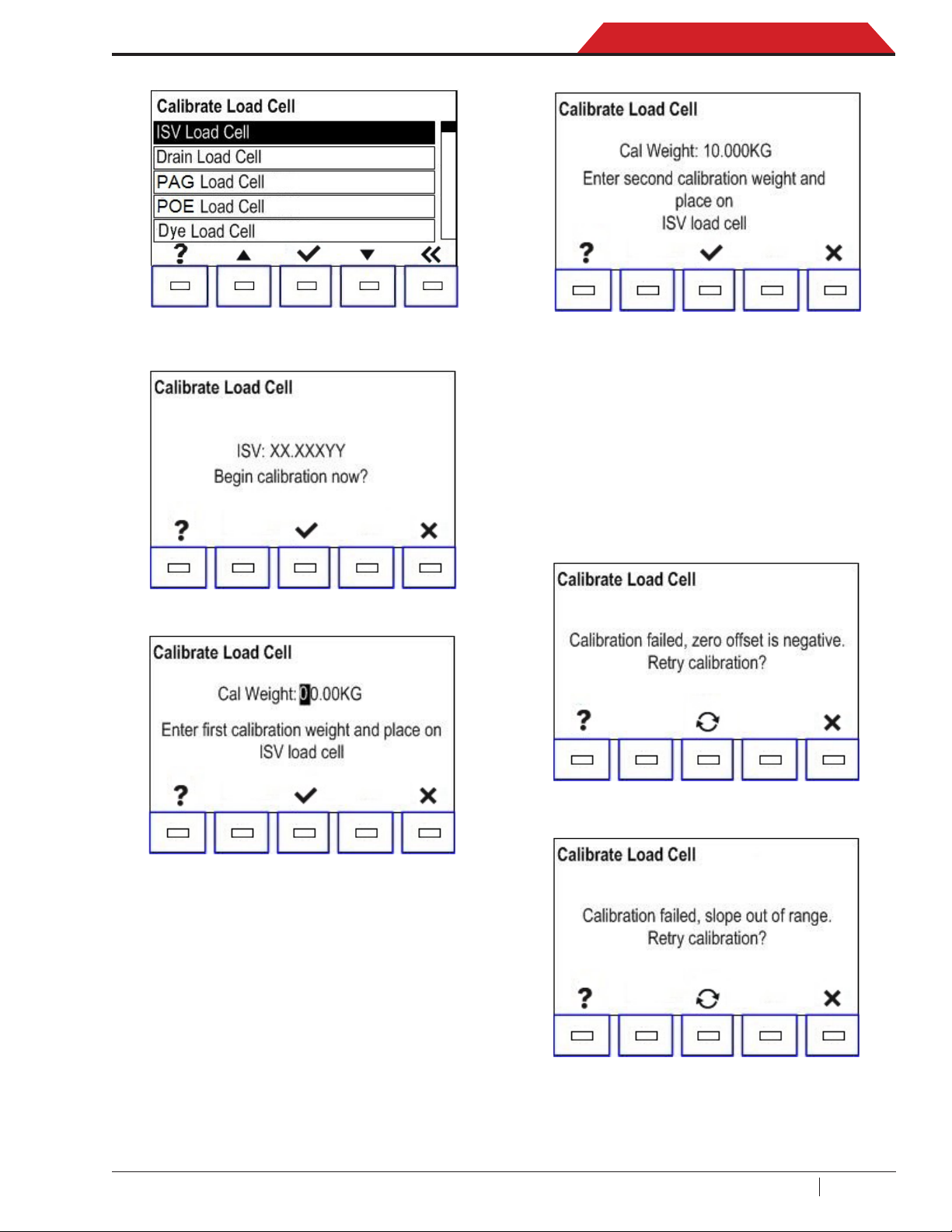
All units include load cell scales: ISV Load Cell,
Drain Load Cell, PAG Load Cell, POE Load Cell
and Dye Load Cell.
ISV Load Cell Calibration
1. After selecting Calibrate Load Cell from
the Service Menu by pressing OK icon, the
following displays:
SP00D00609 2018-03-26 Robert Bosch GmbH
28
ACS 753, ACS 763, ACS 863 Service Manual
Diagnostics and Testing
After 5 seconds:
2. Select OK icon to enter the ISV load cell
calibration.
3. Select OK icon to begin the calibration.
5. Place a 10 kg (editable) weight on the scale
and enter the weight using the keypad.
When nished, select OK icon to save the
entered weight value.
6. If the calibration is accepted, the offset and
slope will be calculated. If either calculation
fails, a fail screen for the offset or slope will
be displayed.
Offset Failure:
4. Use the calibration weight as displayed for
this step. (The rst weight should be 0 as
displayed on the screen.) Select OK icon to
save the displayed weight value.
NOTE: DO NOT DISTURB unit during weight
calibration.
Slope Failure:
The operator is given the opportunity to
retry the calculation or to exit the calibration
function.
29
SP00D00609 2018-03-26Robert Bosch GmbH
Diagnostics and Testing
ACS 753, ACS 763, ACS 863 Service Manual
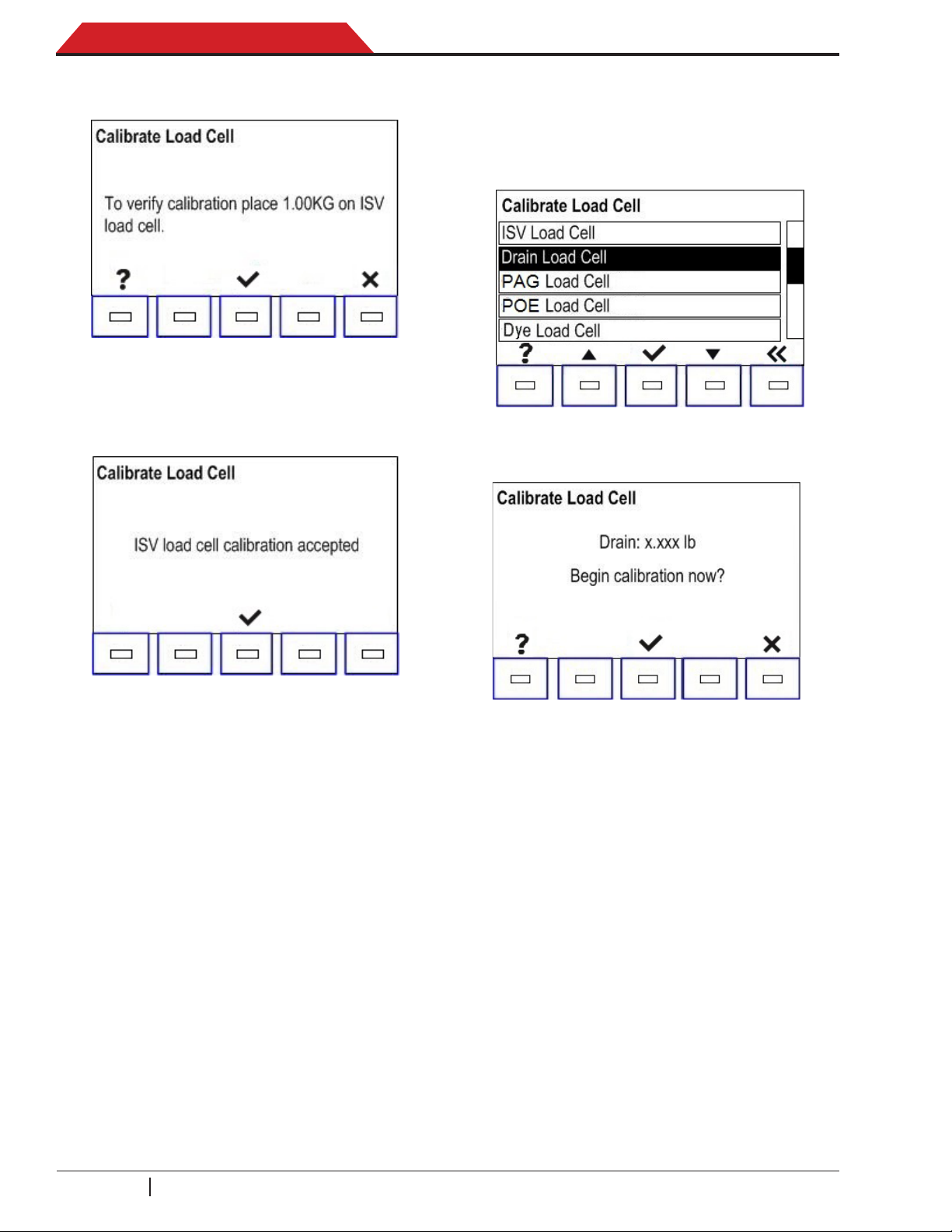
7. If the calculation is accepted, the following
is displayed:
8. Typically adding 1.00 kg (2 lb) is sufcient
to perform this test.
9. If OK icon is selected and the calibration is
accepted, the following displays:
Drain Load Cell Calibration
1. With the Calibrate Load Cell menu displayed,
use the up/down arrow keys to toggle to the
Drain Load Cell service menu. The following
displays:
2. Select OK icon to enter the Drain Load Cell
calibration menu. The following displays:
10. Select OK icon to terminate.
11. If the calibration is not accepted, a Calibration
Failed screen is displayed as shown in Step 6.
12. Selecting ESC icon returns to Calibrate
Load Cell in the service menu.
3. Select OK icon to begin the calibration.
Selecting ESC icon returns to the Calibrate
Load Cell service menu.
Follow all remaining calibration instructions
displayed.
• First point calibration without nothing.
• Second point calibration with 500 g (editable).
• Check with 250 g (not editable) and con-
rm with OK icon.
NOTE: DO NOT DISTURB unit during weight
calibration.
SP00D00609 2018-03-26 Robert Bosch GmbH
30
 Loading...