

Bosch ACS 752 Repair Instructions

ACS 752
de
Repair instruction
A/C Service Unit

Repair instruction ACS 752 3
INDEX
1.0 - GENERAL RULES FOR MAINTENANCE 6
2.0 - Working environment 7
3.0 - INSTALLATION OF THE UNIT 8
3.1 - Unpacking and checking components 8
3.2 - Machine handling and storage 8
3.3 - Preparation for use 9
3.3.1 - Enabling functions description 11
3.4 - Functions 12
3.4.1 - Report management 12
3.4.2 - Pressure test 13
3.4.3 - Diagnosis 13
3.4.4 - Oil scales reset 15
3.4.5 - Multimedia 15
3.4.6 - Tank filling 15
3.4.7 - Oil change 16
3.4.8 - Filter change 16
3.4.9 - Service hoses flushing 16
4.0 - OPERATING PRINCIPLE 17
4.1 - Recovery 17
4.2 - Vacuum 21
4.3 - Oil replenishing 22
4.4 - Charge 23
4.5 - Replenishing compressor oil 25
4.6 - Discharge of non-condensable gases 26
4.7 - UV dye injection 27
4.8 - Service hoses flushing 28
5.0 - DISPLAYED MESSAGES 30
5.1 - Service messages 30
5.2 - Error messages 30
Robert Bosch GmbH 1 689 975 258 – 2014-08-26

4 Repair instruction ACS 752
CYLINDER AND MANIFOLD COMPONENTS LOCATION 30
6.0 -
7.0 - EVACUATION OF THE TOOL 32
8.0 - TROUBLESHOOTING AND DEFECT ANALYSIS 33
8.1 - The station does not recover 33
8.2 - The station does not pull the vacuum 35
8.3 - Non condensable gases are not discharged 36
8.4 - The station does not recycle 36
9.0 - COMPONENTS CHECK AND MAINTENANCE 37
9.1 - Pump 37
9.2 - Pressure transducer P1 38
9.3 - Pressure transducer P2 39
9.4 - Pressure transducer P3 40
9.5 - Safety pressure gauge P4 41
9.6 - Filter dryer change 42
9.7 - Vacuum pump oil change 42
9.8 - AC Unit update process 43
10.0 -SERVICE MENU 44
10.1 - Refrigerant scale calibration 44
10.2 - Oil r e plen i s hing scale calibration 44
10.3 - Oil p u rge scale calibration 45
10.4 - UV dye scale calibration 45
10.5 - T1 temperature sensor calibration 46
10.6 - Tank temperature calibration 46
10.7 - Inputs test 47
10.8 - Outputs test 48
10.9 - Service data 48
10.10 - Oil drain 49
10.11 - Keyboard test 49
10.12 - Display test 49
1 689 975 258 – 2014-08-26 Robert Bosch GmbH

Repair instruction ACS 752 5
11.0 -
DIAGRAMS 50
11.1 - Flow diagram 50
11.2 - Power card 51
11.3 - Motherboard 52
11.4 - Flow diagram components description 54
12.0 -TECHNICAL SPECIFICATIONS 57
13.0 -GLOSSARY OF TERMS 58
Robert Bosch GmbH 1 689 975 258 – 2014-08-26

6 Repair instruction ACS 752
1.0 - GENERAL RULES FOR MAINTENANCE
It is necessary to wear suitable protections such as goggles and gloves, the
contact with the refrigerant can cause blindness as well as other injuries to the
operator.
Avoid the contact with the skin, the low boiling temperature (about -30 °C) may
provoke freezing.
Do not inhale refrigerating gases fumes.
Bef o r e c o nn e ct i n g t h e ACS 752 un i t to a n A /C s y st e m o r to a n e x te r n al t an k , m a k e
sure all the valves are closed.
Before disconnecting the ACS 752 unit, make sure the cycle has been completed
and all the valves are closed thus avoiding to disperse the refrigerating gas in the
air.
Do not modify the safety valves and the control systems calibration.
Do not use tanks or other storing containers which are not type-tested or without
safety valve.
Never charge any container beyond 85% of its capacity, explosion risks may arise.
Never leave the unit live if an immediate use is not scheduled, stop the electrical
supply before a long period of unit inactivity or before internal maintenance
interventions.
Be careful while servicing the unit since connecting hoses may contain pressurised
refrigerant.
Extraordinary maintenance interventions have to be performed by authorised staff
only.
Pressure of leaks of the HCF-134a service equipment or of the air conditioning
systems of the vehicle must not be tested by using compressed air. Some
air/HCF-134a mixtures can burn at high pressures. These mixtures can be
dangerous and may cause fires or explosions and subsequent injuries or damages.
Further information on the operators’ health and safety can be obtained from the
refrigerant producers.
1 689 975 258 – 2014-08-26 Robert Bosch GmbH

Repair instruction ACS 752 7
2.0 - Working environment
The unit has to work in a sufficiently ventilated environment.
CAUTION:
Work far from free flames and hot surfaces; at high temperatures the
refrigerant decomposes freeing toxic and aggressive substances
which are noxious for the user and the environment.
For a correct functioning the unit has to work on an even surface; do not drop nor
bump it.
Do not subject the ACS 752 unit to dripping.
CAUTION:
While operating do not disperse the refrigerant in the environment.
Such a precaution, besides being required by the international rules
for the environment protection, is necessary to prevent the possible
presence of refrigerant in the working environment from making it
difficult to detect possible leaks.
Work in environments with sufficient lighting.
Avoid inhalation of the refrigerants and oils in the A/C systems. Exposure may
cause irritation to eyes and the respiratory tract. To remove R134a from the
A/C system, use only the special recycling-units for R134a. If the refrigerant is
accidentally released into the atmosphere, ventilate the work area before resuming
service.
Do not use the unit under direct sunrays; sun exposure can cause excessive
temperatures and malfunctioning. Working temperatures indicated refer to the unit
being not directly exposed to the sun.
Robert Bosch GmbH 1 689 975 258 – 2014-08-26

8 Repair instruction ACS 752
3.0 - INSTALLATION OF THE UNIT
Please find below operations to perform to start the unit.
CAUTION:
To avoid any problems due to chemical incompatibilities with the
internal components of the service station, use only UV dyes selected
and supplied by Robinair. Problems resulting from the use of any
different types of UV dyes, will cancel the unit warranty.
3.1 - Unpacking and checking components
Remove the machine packaging.
Check to ensure that all of the accessory components are present:
Operating instructions.
4 Graduated bottles.
2 cylinder connectors.
Bottle safety valve conformity certificate.
External temperature probe.
3.2 - Machine handling and storage
CAUTION:
Do not use the rear handle to lift the unit.
Remove the unit from the pallet base of the packaging.
The unit is moved on the four wheels. The two front wheels have brakes.
On rough terrain, the ACS 752 can be moved by tilting it and balancing the weight on
the two rear wheels.
In spite of the fact that the heaviest components have been assembled on the base in
order to lower the centre of gravity, it has not been possible to eliminate the
risk of overturning completely.
1 689 975 258 – 2014-08-26 Robert Bosch GmbH

Repair instruction ACS 752 9
3.3 - Preparation for use
CAUTION:
Connect the unit to a socket provided with grounding protection.
CAUTION:
Make sure the plug and main switch are of easy access to the
operator.
Before starting to use the ACS 752 unit, it is possible to personalize it.
These settings are not compulsory on the standard models.
To personalize the A/C unit comply with the following procedure:
Turn on the unit and wait until the STAND-BY page is displayed.
Press the MENU key.
A menu is displayed containing the operations that may be carried out.
Press the key corresponding to the SET UP function number in order to enter.
LANGUAGE
Select the LANGUAGE function.
The list of languages available in memory is displayed.
Press the cursor shifting key upwards or downwards to scroll the menu and press
OK to set the selected language.
DATE AND TIME
Select the DATE AND TIME function.
The current date and time are displayed and the cursor positions on the date.
Digit the date.
The cursor positions on the time.
Digit the time and press OK to confirm.
Robert Bosch GmbH 1 689 975 258 – 2014-08-26

10 Repair instruction ACS 752
UNITS OF MEASURE
Select the UNITS OF MEASURE function.
The list of units of measure being available in memory is displayed.
Press the cursor shifting key upwards or downwards to scroll the menu and press
OK to set the selected unit of measure.
SYSTEM INFORMATION
Select the SYSTEM INFORMATION function.
The display shows the information on the software release installed on the station.
GARAGE DATA
The data entry is carried out through the keyboard, in a way similar to that used for
mobile phones:
Select the GARAGE DATA function.
Press the numerical keys to select the letters and the characters.
Press the cursor shifting keys to shift among the lines.
Press the left arrow key twice quickly to delete the character preceding the
cursor.
Press OK to memorize the garage data entry.
ACTIVATIONS
Select the ACTIVATIONS function.
A page is displayed where it is possible to enable or disable the following
functions:
Report management (see chapter 3.3.1).
Beeper (see chapter 3.3.1).
UV oil manual (see chapter 3.3.1).
PAG POE (see chapter 3.3.1).
PAGSTKIT (see chapter 3.3.1).
Press the key corresponding to the function number to enable or disable it.
Press OK to confirm.
SERIAL NUMBER
Select the SERIAL NUMBER function.
The display shows the serial number of the station.
1 689 975 258 – 2014-08-26 Robert Bosch GmbH
Repair instruction ACS 752 11
3.3.1 - Enabling functions description
REPORT MANAGEMENT
Function disabled by default. This function is used to enable or disable the report
management (see chapter 3.4.1).
BEEPER
Function enabled by default. This function is used to enable or disable the beeper when
pressing the keys or as a warning during operation.
UV OIL MANUAL
Function disabled by default. This function is used to enable or disable the manual
inclusion of oil and UV dye. If injection oil scales is enabled, oil drain and UV dye are
disabled and the station operates in manual mode; press the MENU button to inject oil
and UV dye and visually check the level in the bottles. A series of messages guide the
operator on the proper use of the operator station.
PAG POE
Function disabled by default. The station is enabled by default to inject only PAG oil
from the oil injection bottle and UV dye injection from its bottle.
This function is to enable the use of both PAG oil and POE oil. If the upper bottle is
enabled, it automatically becomes the bottle of PAG oil and UV dye injection, while the
central bottle automatically becomes the bottle of POE oil and UV dye injection. A series
of messages guide the operator on the proper use of the operator station.
CAUTION:
It is possible to enable this function only on first use and should never
be changed after having used the station. This is to avoid mixtures
that could cause irreversible damage to the A/C system of the vehicle.
Summary table of the type of oil used:
TYPE OF BOTTLE STANDARD MODE PAG/POE MODE
Oil injector glass Oil injection PAG Oil + UV dye
UV dye injector glass UV dye injection POE Oil + UV dye
Oil drain glass Oil drain Oil drain
NOTA BENE:
Once this function has been enabled, if a Charge function or an Automatic one is
started, the station will automatically wash the hoses, after having selected POE oil, in
order not to contaminate the A/C systems that use POE oil.
Robert Bosch GmbH 1 689 975 258 – 2014-08-26

12 Repair instruction ACS 752
PAGSTKIT
Function disabled by default. This function is used to enable or disable the use of the
PAG ST KIT. If enabled, the oil injection value is replaced automatically with a value
calculated specifically for this type of kit. To use the standard oil injection bottle again,
it is necessary to disable the PAG ST KIT function and the value will return to default
automatically.
3.4 - Functions
Press the MENU key from the STAND-BY page and select FUNCTIONS.
The display shows the following functions:
Report management.
Pressure test.
Diagnosis.
Scales reset.
Multimedia.
Tank filling.
Oil change.
Filter change.
Service hoses flushing.
3.4.1 - Report management
If you want to storage and then print the data of the loaded and recovered coolant you
have to enable the “Report Management” function (see ACTIVATIONS chapter 3.3).
Once all data of the loaded and recovered coolant are enabled they are automatically
stored.
Print report
NOTA BENE:
The memory of the station can hold more data than the length of the paper, which is
12 meters long.
To print the stored data proceed as follows:
Select REPORT MANAGEMENT from the FUNCTIONS menu.
The functions menu is displayed.
Select the PRINT REPORT function.
The display shows the stored records quantity.
Press OK to print. Afterwards any record can be deleted.
1 689 975 258 – 2014-08-26 Robert Bosch GmbH

Repair instruction ACS 752 13
Before printing, be sure to have enough paper. It is recommended to print the stored
records at least once a week in order to avoid a too long print which would also be
difficult to consult.
Delete the already printed records so that they will not be accumulated with those
stored afterwards (otherwise they would be printed again in a new print).
Report management with software (optional)
The stored records can be downloaded to a PC. In order to transfer data to the PC
please refer to the software operating manual.
3.4.2 - Pressure test
This feature allows to test a vehicle A/C system pressure with refrigerant inside.
Select PRESSURE TEST from the FUNCTIONS menu.
Follow the messages on the display to perform the operation.
3.4.3 - Diagnosis
It is important to note that the vehicle to be tested should be in a place that is not in
direct sunlight and away from any adverse wind/drafty conditions. The most
insignificant air currents can falsify the performance values drastically.
To evaluate the air conditioning system it is important to follow the procedure below:
LOWER Bonnet.
START engine (engine to be at normal operating temperature).
Stabilise engine rpm at approximately 1500-2000 rpm.
Air conditioning system ON.
Centre face vent OPEN.
Heating setting to maximum COLD.
Interior fan set to HIGH.
Recirculation OFF.
Doors and windows OPEN.
It is recommended to confirm the compressor clutch is engaged before carrying out any
performance tests.
Before recording or inputting any data it is important to note the position of the HVAC
controls, engine temperature / rpm and adequate time has been given to allow the
A/C system to Stabilise (no less than 3 minutes).
Robert Bosch GmbH 1 689 975 258 – 2014-08-26

14 Repair instruction ACS 752
Ambient Temperature - To record the ambient temperature, it is important to take
the temperature of the ambient air at approximately 1metre in front of the car.
Inputting the temperature of the air around the engine compartment may lead to
incorrect diagnosis.
High Side Pressure – With the compressor clutch engaged record the highest high
pressure gauge reading. It is important to note a cycling clutch system will cause the
compressor to cut in and out, thus, the high side pressure will rise and fall. It is the
highest pressure reading that should be recorded.
Low Side Pressure - With the compressor clutch engaged record the lowest low
pressure gauge reading. It is important to note a cycling clutch system will cause the
compressor to cut in and out, thus, the low side pressure will rise and fall.
It is the lowest pressure reading that should be recorded.
Centre Vent Temperature – When taking the centre face vent temperature input a
mean value.
CAUTION:
Air conditioning diagnostic software is designed to assist and guide
professional and competent technicians diagnose air
conditioning/climate control faults. The diagnosis and rectification
offered is to be used for guidance purposes only and in no way should
result in the replacing of components without first being inspected by
the technician and established to be faulty.
Select DIAGNOSIS from the FUNCTIONS menu.
NOTA BENE:
Diagnostics function only work if a vehicle from the database is selected. Otherwise the
program OKs directly the database enabling the selection and memorization of a vehicle
before moving to the diagnostics.
After having selected the vehicle from the database it is possible to enter the data
relevant to the client and press OK.
Insert the ambient temperature measured value.
Insert the high pressure measured value.
Insert the low pressure measured value.
Insert the flap air temperature measured value and press OK.
The diagnosis result is displayed: it consists of the fault possible cause and of the
suggestions to solve the problem.
Press the OK key to print.
Press ESC to quit.
1 689 975 258 – 2014-08-26 Robert Bosch GmbH

Repair instruction ACS 752 15
3.4.4 - Oil scales reset
NOTA BENE:
It is advisable to carry out this operation at regular intervals since it is useful to correct
the zero point deviation of the oil loading cells (this operation is similar to that carried
out for the kitchen scales). Should this operation not be carried out, the unit operation
is not compromised since the software works only by weights difference.
Select SCALES RESET from the FUNCTIONS menu.
The display requires the oil and the UV dye bottles disconnection.
Press the OK key to continue.
The display waits for some seconds before carrying out the automatic reset.
3.4.5 - Multimedia
Select MULTIMEDIA from the FUNCTIONS menu.
The display shows multimedia files.
Use the keys arrow, ENTER, STOP and ESC to manage reproduction.
3.4.6 - Tank filling
Before being able to use the unit, after personalizing it, it is necessary to inject some
coolant in the inner bottle. Comply with the following procedure:
Connect the service pipe to an external container full of coolant
(use the supplied unions).
NOTA BENE:
There are two types of source tanks: one with a liquid outlet and one without.
Tanks with liquid outlets must remain in an upright position in order to transfer the
liquid refrigerant. Use the LIQUID valve connection for this type of tank.
Tanks without liquid outlets are usually equipped with only one valve and have to be
overturned to transfer the liquid refrigerant.
Open the valve on the external bottle and on the service pipe.
Select TANK FILLING from the FUNCTIONS menu.
The display shows the tank available capacity.
Set the amount of coolant that you wish to inject (it is advisable to inject at
least 4-5 kg).
Press OK to start the operation.
Robert Bosch GmbH 1 689 975 258 – 2014-08-26

16 Repair instruction ACS 752
The unit automatically stops once reached the set value.
Close the valve on the source tank.
Press OK to complete the operation and empty the pipes and the still separator.
NOTA BENE:
Usually the final amount of recovered coolant exceeds the set value by about
500-700 g, since also the still separator is emptied.
The function stops automatically when pressure is over in the system.
Press OK to go back to the FUNCTIONS menu.
3.4.7 - Oil change
Vacuum pump oil change function (see chapter 9.7).
3.4.8 - Filter change
Dehydrating filter change function (see chapter 9.6).
3.4.9 - Service hoses flushing
This function allows you to carry out a flushing cycle of the station service hoses.
Select HOSES FLUSHING from the FUNCTIONS menu.
Connect the service hoses both to the low pressure connections and to the high
pressure ones.
Follow the displayed messages to carry out the flushing.
The station automatically stops once the flushing has been completed, press OK to
confirm.
Press OK to go back to the FUNCTIONS menu.
1 689 975 258 – 2014-08-26 Robert Bosch GmbH

Repair instruction ACS 752 17
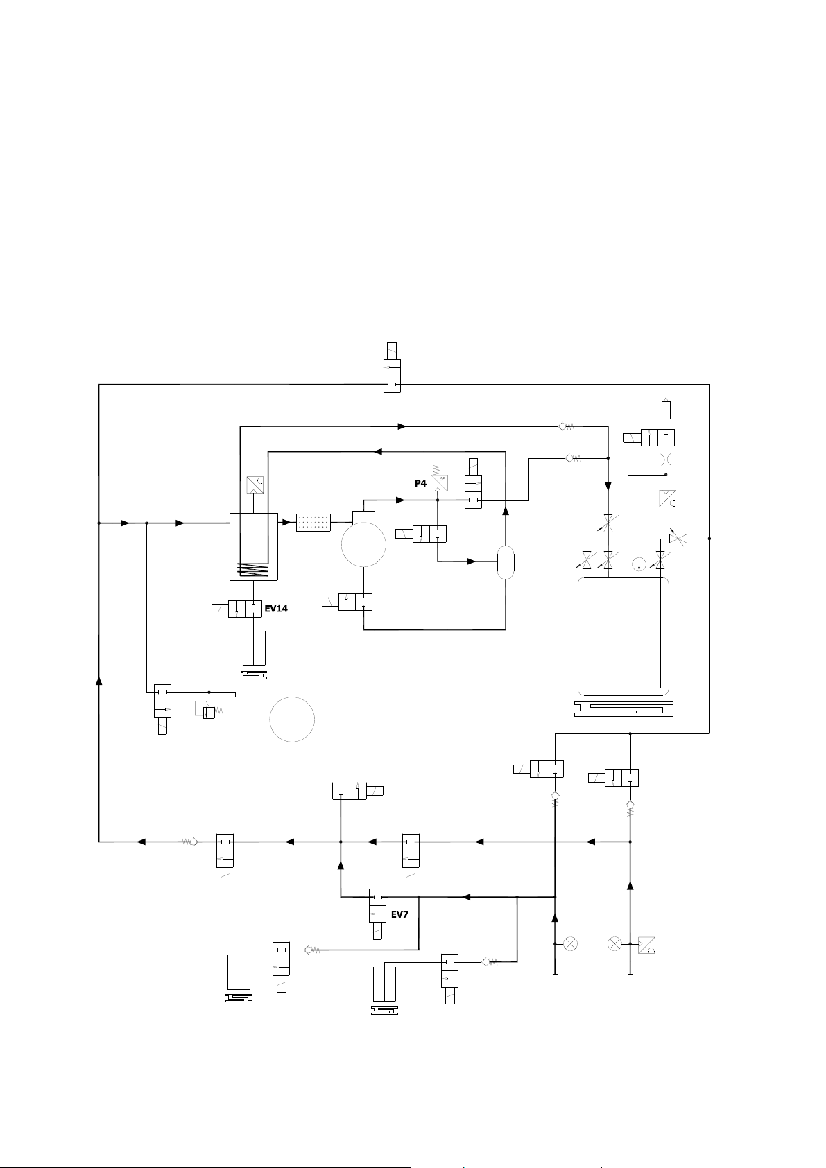
4.0 - OPERATING PRINCIPLE
This chapter presents all of the operating stages. It also presents passage flows inside
the charge station by means of the flow diagram and a short description of active
components in each single function.
4.1 - Recovery
The recovery is the function allowing to eliminate refrigerant from the vehicle A/C
system. The recovery is divided in 3 phases:
1° Phase
Connect the two service hoses T1 (low side) and T2 (high side) to the A/C system of
the vehicle and open the relevant valves on quick couplers: the contained refrigerant
reaches M1 and M2 manometers, the EV7, EV9 solenoid valves and is in contact with
the P1 pressure transducer.
The P1 pressure transducer checks for the presence of refrigerant in the car
A/C system.
If the circuit is under pressure the function starts and the electronic card excites the
EV7, EV9 and EV1 solenoid valves.
The EV10 solenoid valve is excited intermittently to keep a constant input pressure to
the compressor to make it work in the best conditions. The coolant goes through the
still-separator 7, where it is separated from the oil recovered from the A/C system of
the vehicle.
Inside still-separator the refrigerant continues its flow through the filter/drier F1, is
sucked by the compressor, conveyed into the second still/separator 8, cooled through
the cooling coil inside the separator 7 and then stored into the tank.
The filter/drier F1 is used to remove from refrigerant humidity particles before storage
into the tank, while the second still/separator 8 is used to separate refrigerant from
compressor oil of recharge station.
2° Phase
When the pressure of the transducer P2 goes under a certain value set by the
software, solenoid valve EV10 closes, pump 4 starts and solenoid valves EV8 and EV4
are opened.
The length of recovery with the pump can vary from 5 to 15 minutes based on how
long the recovery lasted only with the compressor. In this period, EV12 and EV13 are
excited intermittently to keep the separator pressure at around 0 bar.
Robert Bosch GmbH 1 689 975 258 – 2014-08-26
18 Repair instruction ACS 752
3° Phase
At the end of the recovery with the pump all solenoid valves are closed except for EV1
and EV13. Next, EV1 closes and EV2 opens to clean the last section of the circuit.
After cleaning, EV12 is activated intermittently to keep a pressure in the separator so
as to discharge the oil through EV14.
The flow diagram below highlights the refrigerant flow inside the charge station during
the recovery function.
1° Phase
EV12
EV4
VU3
VU6
13
14
EV15
P3
V2
V4
VU1
VU4
VU5
P2
EV2
F1
V5
V1
V3
EV6
EV1
7
3
11
4
5
EV13
EV8
8
6
9
EV5
VU2
EV9
EV3
VU7
P1
M2 M1
T2 T1
10
EV10
EV16
VU8
1
2
12
1 689 975 258 – 2014-08-26 Robert Bosch GmbH
 Loading...