

Bosch ACS 751, ACS 651 Repair Instructions

ACS 651/751
en
Repair instructions
A/C service unit

2 | ACS 751/651 | en
Contents English
1. Important information 4
2. Testing and resources 4
3. Description 5
3.1 ACS 651/751 5
3.1.1 Front view 5
3.1.2 Rear view 5
3.2 Components 6
3.2.1 Mounting place 6
3.2.2 Human Machine Interface (HMI) 6
3.2.3 Refrigerant cylinder 7
3.2.4 Pressure manifold 7
3.2.5 Vacuum pump 7
3.2.6 Compressor 7
3.2.7 Fan 7
3.2.9 I/O board 8
3.2.8 Human Machine Interface board
(main board) 8
4. Troubleshooting 9
4.1 By status messages 9
4.2 By symptoms 15
4.3 Entering the debug mode 16
4.4 Overview of actuators 16
5. Scales 16
5.1 Calibration of scales 16
5.1.1 Fresh Oil / used oil / UV dye scales 16
5.1.2 Calibration of the refrigerant tank
scale 17
5.2 Replacing scales 18
5.2.1 Replacing used oil/fresh oil/ UV dye
scale 18
5.2.2 Replacing scale assembly for
refrigerant cylinder 19
6. Panels 19
6.1 Opening the top panel 19
6.2 Opening the front panel 20
6.3 Opening the rear panel 20
6.4 Opening the right panel 20
6.5 Opening the left panel 20
6.6 Replacing the front wheels 21
6.7 Replacing the rear wheels 21
7. HMI module 21
7.1 Opening the HMI 21
7.2 Replacing the LCD 22
7.3 Replacing the printer 22
7.4 Replacing the keypad 23
7.5 Replacing the pressure gauges 23
8. Boards 24
8.1 Replacing the HMI board 24
8.2 Replacing the Switch Mode Power Supply
(SMPS) 24
8.3 Replacing the I/O board 24
9. Refrigerant cylinder 25
9.1 Replacing the refrigerant cylinder 25
9.2 Air purging 25
9.3 Replacing the air purge manifold on the
cylinder 26
9.4 Replacing the temperature sensor on the
cylinder 27
10. Pressure Manifold 28
10.1 Replacing the valve block of the pressure
manifold 28
10.2 Replacing the hoses between the
cylinder and the pressure manifold 28
10.3 Replacing the POE solenoid valve 29
10.4 Replacing the POE plug 30
11. Vacuum pump 30
11.1 Replacing the vacuum pump 30
11.2 Checking the vacuum pump function 31
1 689 975 223 2013-10-21| Robert Bosch GmbH
12. Compressor and fan 31
12.1 Replacing the compressor 31
12.2 Checking the compressor function 32
12.3 Replacing the fan assembly 32
13. Replacing the wiring
harness 33
13.1 Replacing the wiring harness 1 33
13.2 Replacing the wiring harness 2 33
13.3 Replacing the wiring harness 3 33
13.4 Replacing the wiring harness 4 34
13.5 Replacing the wiring harness 5 34
13.6 Replacing the wiring harness 6 34
13.7 Replacing the connecting cable for the
temperature sensor 34
13.8 Replacing the USB host cable 34
13.9 Replacing the LED board cable 34
14. Replacing Hoses 35
14.1 Replacing the PA11 hose between the
compressor and the manifold 35
14.2 Replacing the PA11 hose for the HP/LP gauge 35
| ACS 751/651 | 3ACS 751/651 | 3 | 3
en
15. Replacing power supply 36
15.1 Replacing the cable socket 36
15.2 Replacing the fuse 36
14.3 Replacing the PA12 hose for the vacuum pump 36
14.4 Replacing the PA12 hose for the compressor 36
14.5 Replacing the silicon rubber hose for
Fresh-Oil, Used-Oil and UV-Dye 36
14.6 Replacing the hose between the oil separator
and the compressor 36
16. Test Points 37
17. Hydraulic circuit diagram 38
18. Electrical terminal diagram 39
1 689 975 223 2013-10-21| Robert Bosch GmbH

4 | ACS 751/651 | Important informationen
1. Important information
Installation and/or repairs may only be carried out by
trained and instructed Robert Bosch GmbH
customer service staff or organizations authorized by
Robert Bosch GmbH. Opening or modification of the
units by unauthorized persons will invalidate all
warranty entitlements.
Electrical systems and equipment may only be commissioned in proper condition (see Testing Technology
Information 0108_084 for details). This requirement
is met if, after modification or repair (initial test), it is
ensured that the requirements of the electrical engineering regulations are adhered to. To verify this, tests
should be performed, the type and scope of which
should be based on the measures defined in the electrical engineering regulations (e.g. in Germany BGV A3).
In Germany, the type and scope of the tests are described in VDE 0701/0702 Part 1. The corresponding
national regulations must be adhered to.
2. Testing and resources
R General tools for electricians and A/C mechanics
R Digital multimeter
R Loctite 577 for hoses
R Cleaning medium (e.g. brake cleaner)
R Calibration weights for UV dye/oil bottles
(part number F 002 DG1 416)
R Weights for calibration of refrigerant scale - 6 kg
(part number F 002 DG1 650)
1 689 975 223 2013-10-21| Robert Bosch GmbH
Description | ACS 751/651 | 5ACS 751/651 | 5 | 5 en
0
2
4
6
8
10
0
5
10
15
20
25
30
35
12
HP
LP
14
!
2
ABC
3
DEF
6
MNO
ABC
123
8
TUV
7
PQRS
5
JKL
4
GHI
1
c
i
+
*
9
WXYZ
0
]
1 2 3
4
7
6
5
459897_18Nkv
8
9
10
459898_19Nkv
1
2
3
4
567
9
8
3. Description
3.1 ACS 751/651
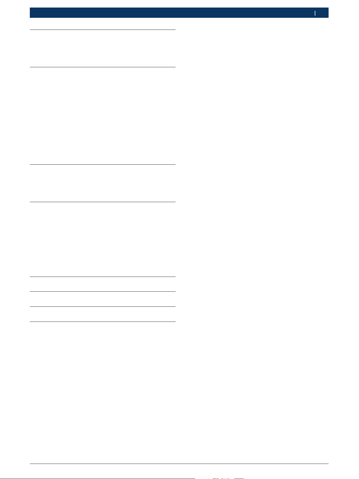
3.1.1 Front view
3.1.2 Rear view
Fig. 2: Rear view
1 HMI support
2 Power switch
Fig. 1: Front view
1 Handle
2 Human Machine Interface (HMI)
3 Top panel
4 Service hatch
5 HP quick coupler
6 Service hoses
7 LP quick coupler
3 Left service hatch
4 Left panel
5 Rear panel
6. Rear wheel with brake
7 Power inlet
8 Power cable
9 Cable holder
8 Front wheel
9 Front service hatch
10 Inline filters
1 689 975 223 2013-10-21| Robert Bosch GmbH
6 | ACS 751/651 | Descriptionen
i
C
!
HP
LP
1
2
3
5
4
6
7
1
2
3
4
5
6
7
8
9
*
+
0
ABC
123
]
459897_6Nkv
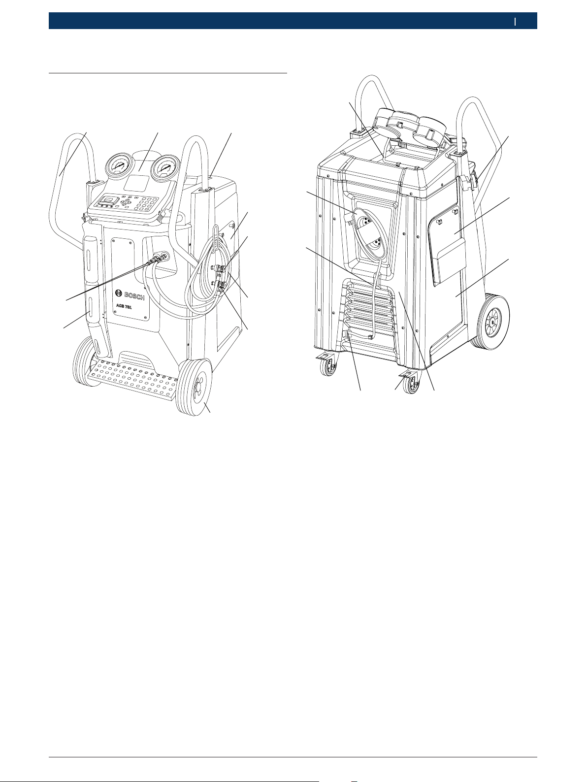
3.2 Components
3.2.1 Mounting place
15
14
13
12
11
3.2.2 Human Machine Interface (HMI)
1
2
3
4
5
6
Fig. 4: ACS 751/651 HMI module
1 HP gauge
2 Status and warning light
3 LP gauge
4 LCD
5 Input keys
6 Selection and function keys
7 Printer
7
459898_21Nkv
10
8
9
Fig. 3: General overview
1 High pressure gauge
2 Low pressure gauge
3 Pressure manifold
4 Air purge manifold
5 Temperature sensor
6 Refrigerant cylinder
7 Oil separator
8 Compressor
9 Fan
10 Used oil bottle
11 Fresh oil bottle
12 Vacuum pump
13 UV dye bottle
14 Keypad
15 LCD
1 689 975 223 2013-10-21| Robert Bosch GmbH
Description | ACS 751/651 | 7ACS 751/651 | 7 | 7 en
459898_9Nkv
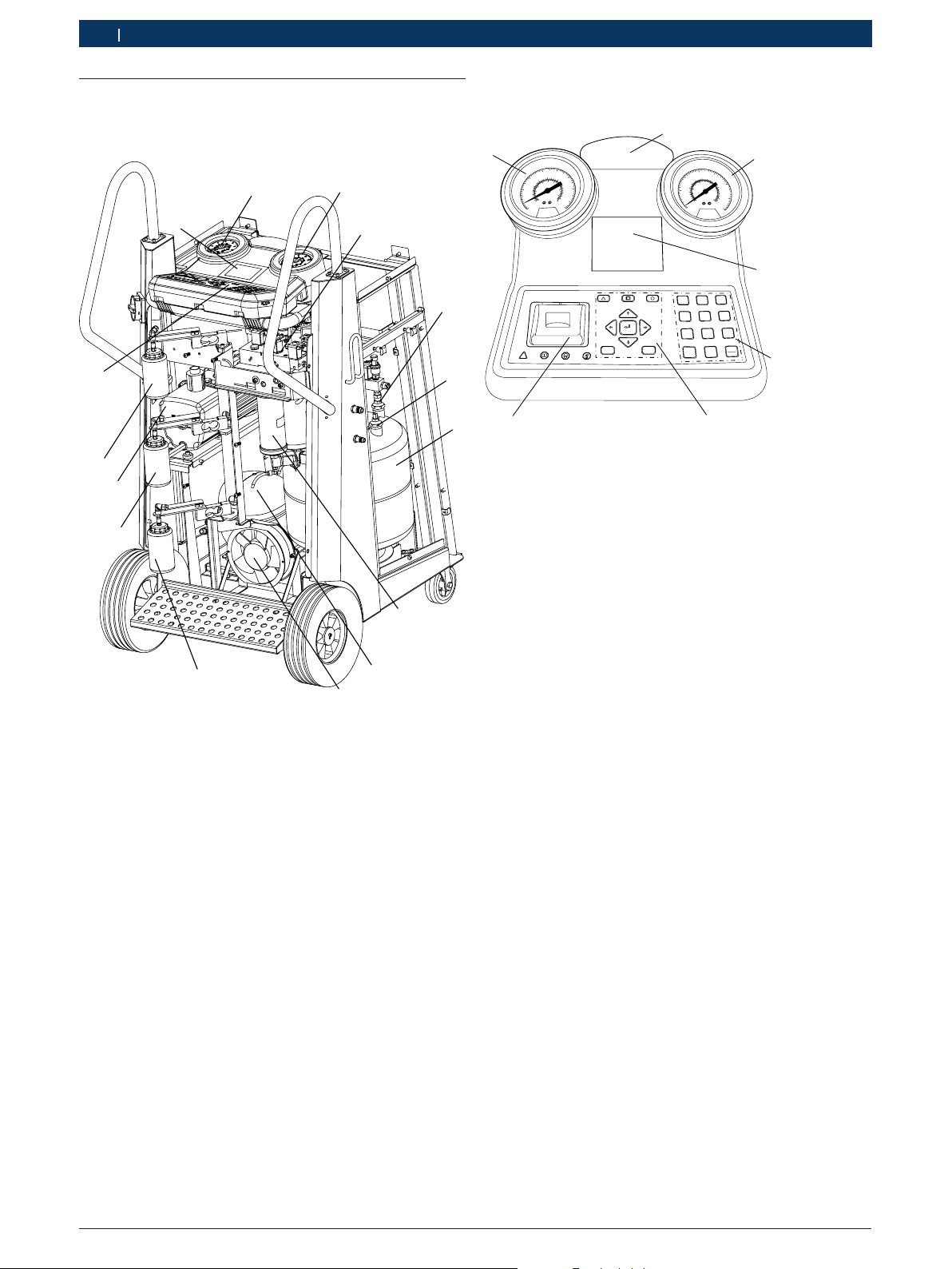
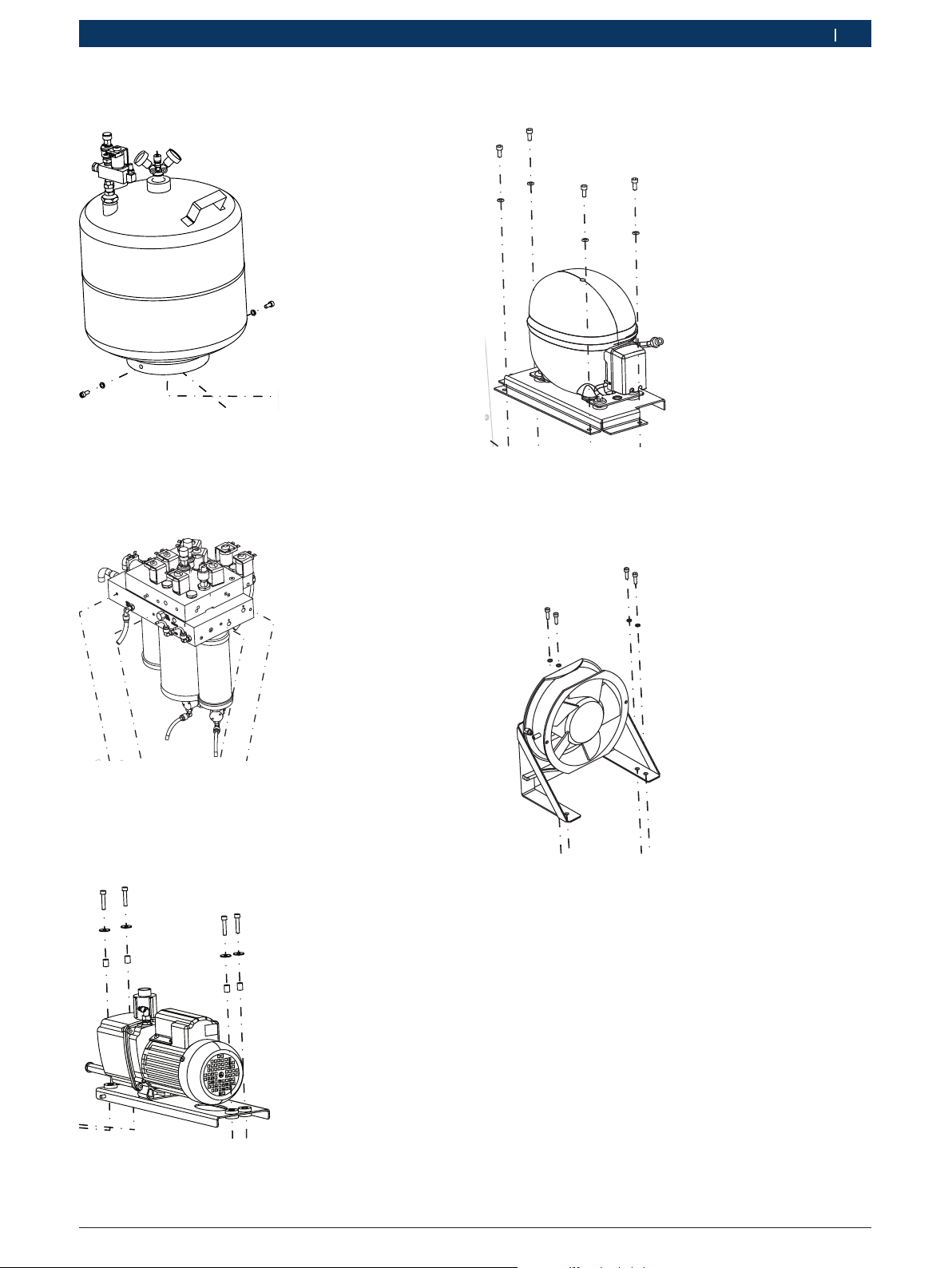
3.2.3 Refrigerant cylinder
Fig. 5: Refrigerant cylinder overview
3.2.4 Pressure manifold
3.2.6 Compressor
Fig. 8: Compressor overview
3.2.7 Fan
Fig. 6: Pressure manifold overview
3.2.5 Vacuum pump
Fig. 7: Vacuum pump overview
Fig. 9: Fan overview
1 689 975 223 2013-10-21| Robert Bosch GmbH
8 | ACS 751/651 | Descriptionen
1
1
2
3
4
5
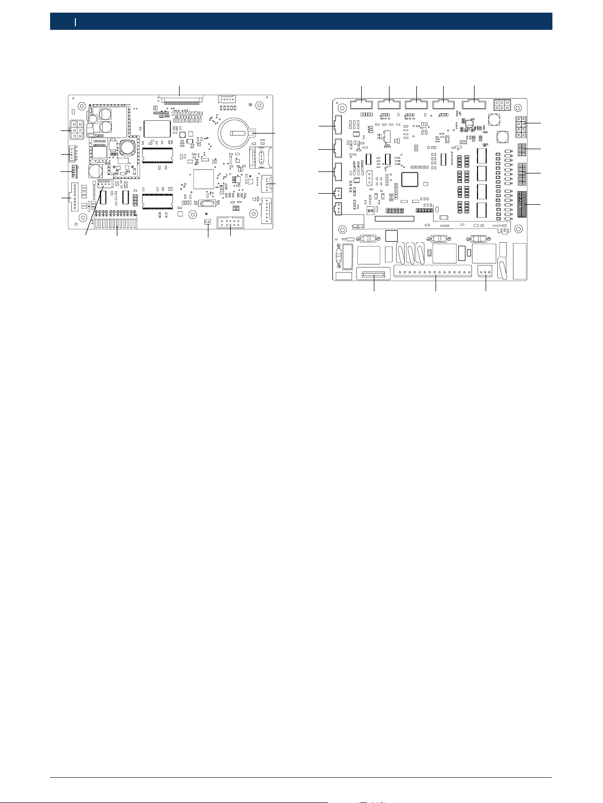
3.2.8 Human Machine Interface board (main board)
11
2
10
9
3
8
459898_29Nkv
7
Fig. 10: HMI Board (main board)
1 Connection to LCD
2 Coin battery CR2032
3 Connection to USB host (for firmware update)
4 Connection to LED
5 Connection to buzzer
6 Connection to keypad
7 Debug - Common port
8 I/O board communication port
9 Connection to printer data
10 Connection to printer power
11 Power from I/O Board
45 6
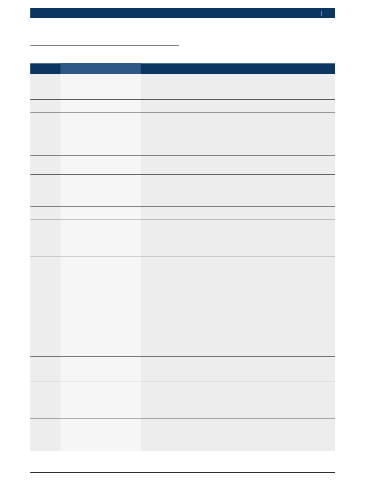
3.2.9 I/O board
16
15
14
13
ACS-NP-IO-C-0030
12 11 10
Fig. 11: I/O Board
1,2,3,4 Connections to scales
5 Connection to HMI board
6 Power to HMI
7 Power from SMPS
8,9 Connection to solenoid valves
10 Connection to safety pressure switch
11 Connection to SMPS, Fan, Vacuum pump and compressor
12 Fuse
13 Connection to temperature sensor
14,15,16 Connection to pressure sensors
6
7
8
9
459898_28Nkv
1 689 975 223 2013-10-21| Robert Bosch GmbH
4. Troubleshooting
4.1 By status messages
Error code Messages Actions
1001 RECOVERY
Service Timeout
1002 RECOVERY
High pressure shutdown
1003 RECOVERY
Used Oil bottle full
1004 RECOVERY
Refrigerant cylinder full
1005 RECOVERY
Used Oil Bottle Not Found
2001 VACUUMING
High Pressure in vehicle. Perform Recovery
2002 VACUUMING
Leak detected
3001 OIL RECHARGE
Service Timeout
3002 OIL RECHARGE
High pressure in vehicle - Perform Recovery?
3003 OIL RECHARGE
High pressure in vehicle - Perform Vacuuming?
3004 OIL RECHARGE
Insufficient Oil Quantity
3006 OIL RECHARGE
Fresh oil Bottle Not Found
4001 UV DYE RECHARGE
Service Timeout
4002 UV DYE RECHARGE
High pressure in vehicle - Perform Recovery?
4003 UV DYE RECHARGE
High pressure in vehicle - Perform Vacuuming
4004 UV DYE RECHARGE
Insufficient UV Dye quantity
4006 UV DYE RECHARGE
UV DYE Bottle Not Found
5001 R134a RECHARGE
Service Timeout
5002 R134a RECHARGE
Insufficient R134a quantity
5003 R134a RECHARGE
Recharge Failed - Check Hoses
R Check for blockage in the vehicle A/C system.
R Check for functionality of pressure sensor (PTA).
R Check for compressor connections.
R Check if internal parts of the manifold have blockage.
R Check for blockage in the vehicle A/C system.
R Check for high pressure switch connection.
R Empty the used oil bottle.
R Perform scale reset.
R Check for used oil bottle scale.
R Weight limit reached. Reduce quantity of refrig-
erant in internal refrigerant cylinder.
R Scale is defective. Replace the scale.
R Check for used oil bottle scale.
R Check if the used oil bottle is disconnected. If the bot-
tle is disconnected, connect the bottle.
R Check the used oil bottle scale.
The pressure is greater than 1400 mbar while vacuuming
R Press "Yes" to continue the recovery.
R Press "No" to abort the operation.
Leakage detected in the vehicle A/C system. Repair the vehicle A/C system.
R Check the oil scale.
R Check for blockage on the oil charge solenoid path.
The pressure is greater than 1400 mbar while recharging.
R Press "Yes" to continue the recovery.
R Press "No" to abort the operation.
The pressure is greater than 1400 mbar while recharging.
R Press "Yes" to continue the recovery.
R Press "No" to abort the operation.
R Oil quantity is less than 30 ml. Refill the oil.
R Reset the fresh oil bottle scale
R Check the fresh oil bottle scale..
R Check if the fresh oil bottle is disconnected. If the bot-
tle is disconnected, connect the bottle.
R Check the oil bottle scale.
R Check for blockage on the oil charge solenoid path.
R Check for blockage in the hoses.
R Check the oil scale.
R Replace the scale.
The pressure is greater than 1400 mbar while recharging.
R Press "Yes" to continue the recovery.
R Press "No" to abort the operation.
The pressure is greater than 800 mbar while recharging.
R Press "Yes" to continue the vacuuming.
R Press "No" to abort the operation.
R UV dye quantity is less than 30 ml. Fill the UV dye bottle.
R Reset the UV dye bottle scale.
R Check the UV dye scale.
R Check for blockage on the oil charge solenoid path
R Check if the UV dye bottle is disconnected. If the bot-
tle is disconnected, connect the bottle.
R Check for blockage on the oil charge solenoid path.
R Check for blockage in the ACS 751/651.
R Check if quick couplers are open.
R Check for blockage in the hoses.
Fill the internal refrigerant cylinder.
R Check if HP and LP quick couplers are open.
R Check if the HP and LP service hoses are blocked.
R Check for blockage in the hoses
Troubleshooting | ACS 751/651 | 9ACS 751/651 | 9 | 9 en
1 689 975 223 2013-10-21| Robert Bosch GmbH
10 | ACS 751/651 | Troubleshootingen
Error code Messages Actions
5004 R134a RECHARGE
High Pressure shutdown
5005 R134a RECHARGE
Refrigerant Cylinder Full
5006 R134a RECHARGE
High Pressure in Vehicle - Perform Recovery?
5007 R134a RECHARGE
High pressure in vehicle - Perform Vacuuming
7100 Safety Switch
High pressure shutdown
7102 PSA
Sensor Connection Failed
7202 PST
Sensor Connection Failed
7302 PSV
Sensor Connection Failed
7402 Tank Temperature
Sensor Connection Failed
7403 Tank Temperature
Sensor Connection Failed
7501 R134a
Timeout
7502 R134a
Sensor Connection Failed
7503 R134a
Sensor Connection Failed
7601 UV Dye
Timeout
R Check the connection to high pressure switch
R Check if the connection to the blue valve on the cylinder is open.
R Check for blockage in the blue hose
R Weight limit reached.
R Reduce quantity of refrigerant in internal refrigerant cylinder.
R Scale is defective. Replace the scale.
R Press "Yes" to perform recharge.
R Press "No" to abort the operation.
R Press "Yes" to perform vacuuming.
R Press "No" to abort the operation.
R Allow the unit to cool for 30 minutes and switch on the unit. Try re-
covery/hose drain. Check if the blue knob on the internal refrigerant tank is closed. Open the blue knob If it is closed.
R Check if the electrical connections to the pressure switch are disconnected.
R Check if there is blockage in the discharge tube/manifold/blue hose be-
tween the tank and valve block. Rectify if there is leakage.
R In debug mode switch on CX and check if compressor is functioning.
R Temporarily interchange the PSA and PSV cable connection at the sen-
sor side. If the error is still with PSA sensor, then replace the top block.
R Check the electrical continuity of the sensor cable including connector at both
ends for each individual wires. If continuity test fails, then change the cable.
R Change the I/O board.
R Temporarily interchange the PST and PSV cable connection at the sen-
sor side. If the error is still with PST sensor, then replace the top block.
R Check the electrical continuity of the sensor cable including connector at both
ends for each individual wires. If continuity test fails, then change the cable.
R Change the I/O board.
R Temporarily interchange the PSV and PSA cable connection at the sen-
sor side. If the error is still with PSV sensor, then replace the top block.
R Check the electrical continuity of the sensor cable including connector at both
ends for each individual wires. If continuity test fails, then change the cable.
R Change the I/O board.
R Check the electrical continuity of the sensor ca-
ble including connector at both ends.
R Measure the resistance across two terminals of the temper-
ature sensor. If the measured resistance is found to be infinity or zero, change the temperature sensor.
R Replace the I/O board.
R Check the electrical continuity of the sensor ca-
ble including connector at both ends.
R Measure the resistance across two terminals of the temper-
ature sensor. If the measured resistance is found to be infinity or zero, change the temperature sensor.
R Replace the I/O board.
Replace the I/O board.
R Measure the resistance across:
- Red-Black
- Green-White
If any of the two measurement shows inifinite resistance, change the load sensor.
R Change the I/O board.
R Measure the resistance across
- Red-Black
- Green-White
If any of the two measurement shows inifinite resistance, change the load sensor.
R Change the I/O board.
Replace the I/O board.
1 689 975 223 2013-10-21| Robert Bosch GmbH
Error code Messages Actions
7602 UV Dye
Sensor Connection Failed
7603 UV Dye
Sensor Connection Failed
7701 Fresh Oil
Timeout
7702 Fresh Oil
Sensor Connection Failed
7703 Fresh Oil
Sensor Connection Failed
7801 Used Oil
Timeout
7802 Used Oil
Sensor Connection Failed
7803 Used Oil
Sensor Connection Failed
7804 Used Oil
Invalid Range
8000 SYSTEM ERROR
Retry Operation. Contact techsupport if problem persists
9001 FIRMWARE UPDATE Retry Op-
eration. Contact tech-support if problem persists.
9201 SYSTEM ERROR
No USB detected
9203 SYSTEM ERROR Retry Op-
eration. Contact tech-support if problem persists.
9204 SYSTEM ERROR Retry Op-
eration. Contact tech-support if problem persists.
9205 SYSTEM ERROR Retry Op-
eration. Contact tech-support if problem persists
9206 SYSTEM ERROR Retry Op-
eration. Contact tech-support if problem persists
9207 SYSTEM ERROR Retry Op-
eration. Contact tech-support if problem persists
9208 SYSTEM ERROR Retry Op-
eration. Contact tech-support if problem persists
R Measure the resistance across
- Red-Black
- Green-White
If any of the two measurement shows inifinite resistance, change the load sensor.
R Change the I/O board.
R Measure the resistance across:
- Red-Black
- Green-White
If any of the two measurement shows inifinite resistance, change the load sensor.
R Change the I/O board.
Replace the I/O board.
R Measure the resistance across:
- Red-Black
- Green-White
If any of the two measurement shows inifinite resistance, change the load sensor.
R Change the I/O board.
R Measure the resistance across
- Red-Black
- Green-White
If any of the two measurement shows inifinite resistance, change the load sensor.
R Change the I/O board.
Replace the I/O board.
R Measure the resistance across:
- Red-Black
- Green-White
If any of the two measurement shows inifinite resistance, change the load sensor.
R Change the I/O board.
R Measure the resistance across:
- Red-Black
- Green-White
If any of the two measurement shows inifinite resistance, change the load sensor.
R Change the I/O board.
R Allow the unit to cool for 30 minutes and switch on the unit. Try re-
covery/hose drain. Check if the blue knob on the internal refrigerant tank is closed. Open the blue knob If it is closed.
R Check if the electrical connections to the pressure switch are disconnected.
R Check if there is blockage in the discharge tube/manifold/blue hose be-
tween the tank and valve block. Rectify if there is leakage.
R In debug mode switch on CX and check if compressor is functioning.
Check the cable connection between the HMI board and the I/O board.
or
Replace the HMI board.
R Check the HMI board.
R Check the USB connection.
R Replace the HMI board.
Check if the USB disk is connected to the USB port.
R Check the HMI board.
R Check the USB connection.
R Replace the HMI board.
R Check the HMI board.
R Check the USB connection.
R Replace the HMI board.
R Check the HMI board.
R Check the USB connection.
R Replace the HMI board.
R Check the HMI board.
R Check the USB connection.
R Replace the HMI board.
R Check the HMI board.
R Check the USB connection.
R Replace the HMI board.
R Check the HMI board.
R Check the USB connection.
R Replace the HMI board.
Troubleshooting | ACS 751/651 | 11ACS 751/651 | 11 | 11 en
1 689 975 223 2013-10-21| Robert Bosch GmbH
12 | ACS 751/651 | Troubleshootingen
Error code Messages Actions
9209 SYSTEM ERROR Retry Op-
eration. Contact tech-support if problem persists
920A SYSTEM ERROR Retry Op-
eration. Contact tech-support if problem persists
920B SYSTEM ERROR Retry Op-
eration. Contact tech-support if problem persists
920C SYSTEM ERROR Retry Op-
eration. Contact tech-support if problem persists
R Check the HMI board.
R Check the USB connection.
R Replace the HMI board.
R Check the HMI board.
R Check the USB connection.
R Replace the HMI board.
R Check the HMI board.
R Check the USB connection.
R Replace the HMI board.
R Check the HMI board.
R Check the USB connection.
R Replace the HMI board.
920D SYSTEM ERROR Retry Op-
eration. Contact tech-support if problem persists
920E SYSTEM ERROR Retry Op-
eration. Contact tech-support if problem persists
920F SYSTEM ERROR Retry Op-
eration. Contact tech-support if problem persists
9300 SELF TEST FAILED
View Detail?
9400 RTC Failed Replace the HMI board.
9600 PRINTER
Out of paper
A101 INTERNAL BOTTLE FILL
Service Timeout
A102 INTERNAL BOTTLE FILL
Used Oil bottle full
A103 INTERNAL BOTTLE FILL Re-
frigerant Cylinder Full
A104 INTERNAL BOTTLE FILL
High Pressure shutdown
A105 INTERNAL BOTTLE FILL
Low Pressure - Check external cylinder valve
A202 SHORT FLUSHING
Service timeout
A203 SHORT FLUSHING
Insufficient R134a quantity
A204 SHORT FLUSHING
Leak Detected
A205 SHORT FLUSHING
High Pressure shutdown
R Check the HMI board.
R Check the USB connection.
R Replace the HMI board.
R Check the HMI board.
R Check the USB connection.
R Replace the HMI board.
R Check the HMI board.
R Check the USB connection.
R Replace the HMI board.
Press "Yes" to view details. Press "No" to continue.
R Check if paper roll is present in the printer. If not, insert paper roll.
To order printer paper, use the order number F 002 DG1 450.
R Check for blockage in ACS 751/651.
R Check R134a scale.
Check if the used oil bottle is full. If the bottle is full, empty the bottle.
R Weight limit reached. Reduce quantity of refriger-
ant in the internal refrigerant cylinder.
R Refrigerant cylinder scale is defective. Replace the scale.
R Check for blockage in the vehicle A/C system.
R Check the connection to the high pressure switch.
R Check if the connection to the blue valve on the cylinder is open.
R Check for blockage in the blue hose.
R Check if the valve on the external cylinder is open.
R Check if R134a is available in the external cylinder.
R Check for blockage in the ACS 651/751.
Fill the internal refrigerant cylinder.
Repair the vehicle A/C system or part under flushing.
R Check for blockage in the vehicle A/C system.
R Check the connection to the high pressure switch.
R Check if the connection to the blue valve on the cylinder is open.
R Check for blockage in the blue hose.
A206 SHORT FLUSHING
High Pressure in vehicle. Perform Recovery?
1 689 975 223 2013-10-21| Robert Bosch GmbH
The pressure is greater than 1400 mbar while vacuuming Press "Yes"
to continue the recovery. Press "No" to abort the operation.
 Loading...