

Bosch ACS 611 Original Instructions Manual
ACS 611
de
Originalbetriebsanleitung
Klimaservicegerät
en
Original instructions
A/C service-unit
fr
Notice originale
Appareil de SAV pour climatiseur
es
Manual original
Aparato de servicios de aire
acondicionado
it
Istruzioni originali
Attrezzatura per assistenza
climatizzatore
sv
Bruksanvisning i original
A/C serviceenhet
nl
Oorspronkelijke gebruiksaanwijzing
Airco-onderhoudsapparaat
pt
Manual original
Aparelho de manutenção de sistemas
de ar condicionado
fi
Alkuperäiset ohjeet
A/C huoltolaite
da
Original brugsanvisning
A/C tjenesten Unit
no
Original driftsinstruks
A/C tjenesten Unit
pl
Oryginalna instrukcja eksploatacji
Urządzenie do obsługi układu
klimatyzacji
cs
Původní návod k používání
Přístroj na servis klimatizací vozidel
tr
Orijinal işletme talimatı
A/C servis ünitesi
ru
Оригинальное руководство по эксплуатации
Подготовка к обслуживанию

S P00 D00 002 2013-04-10
|
Robert Bosch GmbH
32 | ACS 611 |
en
1. Symbols used 34
1.1 In the documentation 34
1.1.1 Warning notices Structure and meaning 34
1.1.2 Symbols in this documentation 34
1.2 On the product 34
2. Important notes 34
2.1 User group 34
2.2 Agreement 34
2.3 Obligation of contractor 35
2.4 Safety regulations 36
2.5 Safety devices 37
3. Product description 38
3.1 Application 38
3.2 Delivery specification 38
3.3 Overview on software texts 38
3.4 Description of unit 39
3.4.1 Selection and function keys 40
3.4.2 Input keys 41
3.4.3 Printer 41
3.4.4 Service flap 41
3.4.5 Scales for
refrigerant, fresh oil and used oil 41
3.4.6 Service hose and service quick-release
coupling 42
3.4.7 Locking brakes 42
3.4.8 Power cord 42
3.4.9 Master switch 42
3.5 Description of function 42
4. Program structure 43
4.1 Calibration and tare 43
4.2 Settings 43
4.3 Repair 43
4.4 Vehicle and customer data 43
4.5 Menu 43
4.6 Manual mode 43
4.7 Automatic mode 43
4.8 Flush (optional) 43
4.9 Enter 43
5. Initial commissioning 44
5.1 Removing transportation packaging 44
5.2 Switching on the ACS 611 44
5.3 Required settings 44
5.3.1 Setting the language 44
5.3.2 Setting the date and time 44
5.3.3 Set workshop data 45
5.3.4 Enter serial number 45
5.4 Internal Refrigerant cylinder 45
5.4.1 Checking type of connection of
external refrigerant cylinder 45
5.4.2 Filling internal refrigerant cylinder 46
6. A/C service preparation 46
7. Operating instructions 47
7.1 Database 47
7.1.1 Vehicle database 47
7.1.2 Personal database 47
7.1.3 Customer and vehicle data 47
7.2 Service phases 47
7.3 Manual service 48
7.3.1 Filling of refrigerant, fresh
oil and UV dye 48
7.3.2 Recovery 49
7.3.3 Vacuum 49
7.4 Automatic service 49
7.5 Processing 50
8. Troubleshooting 51
8.1 Service prompt 51
8.2 Fault messages 51
9. Diagnosis 52
9.1 Preparatory work 52
9.2 Diagnosis 52
10. ACS 611 settings 53
10.1 Set unit 53
10.2 Set length of service hoses 53
10.3 Contrast 53
10.4 Flush (optional) 53
10.5 Scales for fresh and used oil 53
10.6 UV dye 53
10.7 Service data report 54
10.7.1 Activate/deactivate consumption
R134a report 54
10.7.2 Report printout 54
Contents English

S P00 D00 002 2013-04-10
|
Robert Bosch GmbH
| ACS 611 | 33
en
11. Maintenance 54
11.1 Spare and wearing parts 54
11.2 Maintenance interval 54
11.3 Tare oil scales 55
11.4 Calibration of scales 55
11.4.1 Calibrating internal refrigerant cylinder 55
11.4.2 Fresh oil and used oil scales 55
11.5 Vacuum pump 56
11.5.1 Changing vacuum pump oil 56
11.5.2 Reset of oil change interval 56
11.6 Combo filter 57
11.6.1 Replacement of combo filter 57
11.6.2 Reset filter 57
11.7 Software update 57
11.7.1 irmware 57
11.7.2 Vehicle database 58
11.8 Replacing printer paper 58
12. Disposal 58
12.1 Disposal of electronic parts 58
12.2 Disposal of LCD display 58
12.3 Disposal of refrigerants, UV dye,
lubricants and oils 58
12.4 Disposal of combo filter 58
13. Technical data 59
13.1 ACS 611 59
13.2 Ambient temperature 59
13.3 Electromagnetic compatibility 59
14. Glossary 59
S P00 D00 002 2013-04-10
|
Robert Bosch GmbH
34 | ACS 611 | Symbols used
en
1. Symbols used
1.1 In the documentation
1.1.1 Warning notices - Structure and meaning
Warning notices warn of dangers to the user or people
in the vicinity. Warning notices also indicate the
consequences of the hazard as well as preventive action.
Warning notices have the following structure:
Warning
symbol
KEY WORD – Nature and source of hazard!
Consequences of hazard in the event of
failure to observe action and information
given.
¶ Hazard prevention action and information.
The key word indicates the likelihood of occurrence and
the severity of the hazard in the event of non-observance:
Key word Probability of
occurrence
Severity of danger if
instructions not observed
DANGER Immediate impending
danger
Death or severe injury
WARNING Possible impending
danger
Death or severe injury
CAUTION Possible dangerous
situation
Minor injury
1.1.2 Symbols in this documentation
Symbol Designation Explanation
!
Attention Warns about possible property damage.
i
Information Practical hints and other
useful information.
1.
2.
Multi-step
operation
Instruction consisting of several steps.
e
One-step
operation
Instruction consisting of one step.
Intermediate
result
An instruction produces a visible
intermediate result.
"
Final result There is a visible final result on
completion of the instruction.
1.2 On the product
!
Observe all warning notices on products and ensure
they remain legible.
2. Important notes
Before start up, connecting and operating
Bosch products it is absolutely essential
that the operating instructions/owner’s
manual and, in particular, the safety
instructions are studied carefully. By doing so you can
eliminate any uncertainties in handling Bosch products
and thus associated safety risks upfront; something
which is in the interests of your own safety and will
ultimately help avoid damage to the device. When a
Bosch product is handed over to another person, not
only the operating instructions but also the safety
instructions and information on its designated use must
be handed over to the person.
2.1 User group
The product may be used by skilled and instructed
personnel only. Personnel scheduled to be trained,
familiarized, instructed or to take part in a general
training course may only work with the product under
the supervision of an experienced person.
All work conducted on pressurized equipment may be
performed by persons with sufficient knowledge and
experience in the field of refrigeration, cooling systems
and coolants and, also be aware of the risks involved in
the use of pressurized devices.
2.2 Agreement
By using the product you agree to the following regulations:
Copyright
Software and data are the property of
Robert Bosch GmbH or its suppliers and protected
against copying by copyright laws, international
agreements and other national legal regulations.
Copying or selling of data and software or any part
thereof is impermissible and punishable; in the event of
any infringements Bosch reserves the right to proceed
with criminal prosecution and to claim for damages.
¶ Wear safety goggles.
¶ Wear protective gloves.
¶ Protect against dampness and moisture.

S P00 D00 002 2013-04-10
|
Robert Bosch GmbH
Symbols used | ACS 611 | 35
en
2.3 Obligation of contractor
The contractor is obliged to ensure that all measures
geared towards the prevention of accidents, industrial
diseases, labor-related health risks are taken and
measures towards making the workplace fit for people
to work in are carried out.
Specifications for electrical systems (BGV A3)
Electrical engineering in Germany is subject to
the accident prevention regulations of the trade
association "Electrical Plant and Equipment as under
BGV A3 (previously VBG 4)". In all other countries, the
applicable national regulations acts or decrees are to be
adhered to.
Liability
All data in this program is based - where possible - on
manufacturer and importer details. Bosch does not
accept liability for the correctness and completeness of
software and data; liability for damage caused by faulty
software and data is ruled out. Whatever the event,
Bosch liability is restricted to the amount for which the
customer actually pays for this product. This disclaimer
of liability does not apply to damages caused by intent
or gross negligence on the part of Bosch.
Warranty
Any use of non-approved hardware and software will
result in a modification to our product and thus to
exclusion of any liability and warranty, even if the
hardware or software has in the meantime been
removed or deleted.
No changes may be made to our products. Our
products may only be used in combination with original
accessories and original service parts. Failing to do so,
will render null and void all warranty claims.
This product may only be operated using Bosch
approved operating systems. If the product is operated
using an operating system other than the approved one,
then our warranty obligation pursuant to our supply
conditions will be rendered null and void. Furthermore,
we will not be held liable for damage and consequential
damage incurred through the use of a non-approved
operating system.
Basic rules
The contractor is bound to ensure that all electrical
equipment and operating material is set up, modified
and maintained by skilled electricians only or under
the guidance and supervision of a skilled electrician in
accordance with electrical engineering principles.
Furthermore, the contractor must ensure that all
electrical equipment and operating material is operated
in keeping with electrical engineering principles.
If a piece of electrical equipment or operating material
is found to be defective, i.e. it does not or no longer
complies with electrical engineering principles, the
contractor must ensure that the fault is rectified
immediately and, in the event that imminent danger
exists, also ensure that the electrical equipment or the
electrical operating material is not used.
Tests (taking Germany as an example):
R The contractor must ensure that all electrical
systems and equipment are tested by a qualified
electrician or under the guidance of a qualified
electrician to ensure they are in proper working
order:
$ Before starting for the first time.
$ After modification or repair before starting for the
first time.
$ At given intervals. Set intervals such as to ensure
that faults that can be expected to occur are
determined in good time.
R The test is to take the electrical engineering
principles relating hereto into account.
R Upon request of the trade association, a test manual
is to be maintained into which specific entries are
made.
S P00 D00 002 2013-04-10
|
Robert Bosch GmbH
36 | ACS 611 | Symbols used
en
2.4 Safety regulations
Always carefully read and observe all the safety
regulations before using the Bosch product.
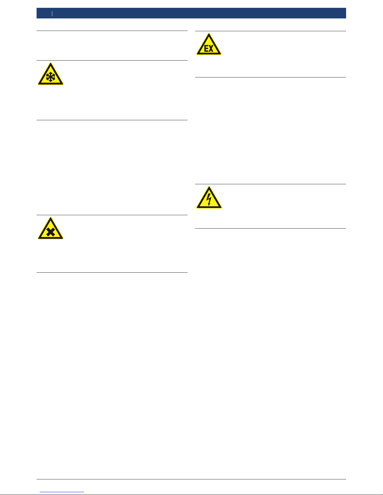
Avoid all skin contact with the refrigerant.
The low boiling point of the refrigerant
(approx. -30 °C) can lead to frostbites.
Should it nevertheless come into contact
with the skin, remove any moistened clothing
immediately and rinse the affected skin with
copious amounts of water.
R Avoid all skin contact with the UV dye. Should
it nevertheless come into contact with the skin,
remove any moistened clothing immediately and
rinse the affected skin with copious amounts of
water.
R R134a is colorless, has a weak intrinsic odor and
is heavier than air. It displaces oxygen and may
flow into repair pits. Should refrigerant escape
(malfunction), always ensure adequate ventilation
and air extraction (especially in pits). Exit the
workshop.
Never inhale refrigerant, dye and oil vapors.
The vapors can irritate the eyes, nose and
respiratory system. If liquid refrigerant or UV
dye comes into contact with the eyes, rinse
them thoroughly with water for 15 minutes.
Then obtain medical help even if no pain is
felt.
R Never swallow UV dye. If swallowed inadvertently,
never attempt to induce vomiting. Drink copious
amounts of water and obtain medical help.
R Before connecting the ACS 611 to a vehicle air
conditioner or an external refrigerant cylinder, make
sure the quick-release couplings are not leaking.
Only ever use external refrigerant cylinders provided
with safety valves and certified in line with the
applicable standards.
R Before switching off the ACS 611, make sure all
filling and drainage operations have been completed.
This prevents refrigerant escaping into the
environment.
Never use compressed air with R134a.
Certain mixtures of air and R134a are highly
flammable. Such mixtures are a potential
hazard and may lead to fire or explosions
and thus cause damage or injury.
R Refrigerant extracted from a vehicle air conditioner
may be contaminated with moisture, lubricant, dirt
and traces of other gases.
R R134a is not to be used in areas in which there is a
danger of explosion. Fire, naked flames and smoking
are prohibited. Welding and soldering are not
permitted.
R High temperatures and UV radiation may chemically
separate the R134a. The resultant products cause
coughing and nausea.
R R134a is not to be mixed with other refrigerants.
Themixing of refrigerants could damage the vehicle
air conditioner.
If high-voltage components or high-voltage
wires are inappropriately handled, there is a
risk of fatal injury from high voltages and the
possible transmission of current through the
body.
R De-energization is only to be performed by a
qualified electrician, a qualified electrician for
specific tasks (hybrid), or a power systems engineer.
R Work on vehicles with high-voltage components is
only ever to be performed in a safe, de-energized
condition by persons with the minimum qualification
"Trained to perform electrical work".
R Even after deactivating the high-voltage vehicle
electrical system, the high-voltage battery may still
be live.
R The operating condition cannot be established from
any running noise, as the electric machine is silent
when stationary.
R In gear positions "P" and "N" the engine or electric
motor may start spontaneously depending on the
charge of the high-voltage battery.
R Never open or damage high-voltage batteries.
R On accident vehicles, never touch high-voltage
components or exposed high-voltage wires before
deactivating the high-voltage vehicle electrical
system.

S P00 D00 002 2013-04-10
|
Robert Bosch GmbH
Symbols used | ACS 611 | 37
en
R The ACS 611 must be constantly monitored when
in operation. Never leave the ACS 611 unattended
when in operation.
R The vehicle A/C service using the ACS 611 must
be prepared and implemented so that the vehicle
air conditioner circuit does not have to be opened
(forexample by removing the radiator or engine).
R Position the ACS 611 on all four wheels on a flat,
vibration-proof surface so that proper operation
ofthe scales is guaranteed.
R The ACS 611 can be secured in position by locking
the brake.
R The ACS 611 must always be transported in its
operating position. Never lay the ACS 611 on its
side, as oil could then escape from the vacuum
pump, or the built-in compressor could be damaged.
R There are no additional safety systems for protecting
the ACS 611 against damage resulting from natural
catastrophes.
R Never remove any components from inside the
ACS 611 except for maintenance or repair purposes.
R Observe the pertinent legal regulations or directives
to ensure safe handling of pressurized devices.
R We recommend calibrating the scales and pressure
sensors at least once per year. Contact customer
service for calibrating the scales of the internal
refrigerant cylinder.
R Never perform any maintenance work which is not
expressly recommended in this manual. Contact
customer service if components have to be replaced
other than in the course of maintenance work.
R ACS 611 must be connected to a properly grounded
electrical connection.
R If damage to the ACS 611 is established, terminate
usage immediately and contact customer service.
R The service hoses and quick-release couplings
must be regularly checked for wear and replaced
ifdamaged.
R The ACS 611 must be operated in an environment
corresponding to the directive BGR 157 with respect
to the exchange of air.
R Observe local laws or directives so as to ensure the
safety of the pressurized device.
R For safety reasons it is advisable to use a residual
current operated circuit breaker (rccb) with the
following specifications:
Parameters Specification
Rated voltage
230 VAC ± 10 %
Rated frequency
50/60 Hz
Rated current 230 VAC 6,3 A
Rated tripping current
30 mA
Tripping switch
C
2.5 Safety devices
Description Operation
Pressure switch Switches the compressor off if the normal
operating pressure is exceeded.
Safety valve The safety valve opens if the design
pressure is exceeded.
Fuse
Interrupts the power supply if overcurrent
is applied to the ACS 611.
Vents
The ACS 611 is provided with vents in
the bottom of the housing to ensure the
exchange of air even when switched off.

S P00 D00 002 2013-04-10
|
Robert Bosch GmbH
38 | ACS 611 | Product description
en
3. Product description
3.1 Application
ACS 611 is suitable for vehicles with conventional
combustion engines (PAG oil) as well as for hybrid
and electric vehicles (POE oil). ACS 611 features all
functions necessary for the air conditioning service of
vehicles.
! ACS 611 can be operated with either PAG or POE
oil. Mixing the oils causes damage to the vehicle
air conditioning system. For this reason, the oil
types must not be changed after the first vehicle air
conditioning service.
The following functions can be implemented:
R Refrigerant removal by suction and filling.
R Refrigerant processing.
R Vacuum creation.
R Addition of oil.
R Addition of UV dye.
R Flushing.
! The ACS 611 is only to be operated with R134a
refrigerant. The ACS 611 is not to be used for service
work on vehicles with air conditioning systems
employing refrigerants other than R134a, as this will
cause damage. Check the type of refrigerant used in
the vehicle air conditioner prior to A/C service.
3.2 Delivery specification
Description Order number
ACS 611 –
Safety goggles
–
Protective gloves
–
Original instructions
SP00D00002
External refrigerant cylinder adapter set
big
small
SP00100019
SP00100080
1)
Pre-assembled.
3.3 Overview on software texts
Software Orig. operating instructions
UV DYE
UV dye
HOSES LENGTH
Service hose length
TANK
Internal refrigerant cylinder
IN OIL Fresh oil
OIL OUT Used oil
HOSES
Service hoses
SELECT PORTS
Vehicle air-conditioning system
service connection (service quick-
release coupling)
CHANGE OIL
Vacuum pump
S P00 D00 002 2013-04-10
|
Robert Bosch GmbH
Product description | ACS 611 | 39
en
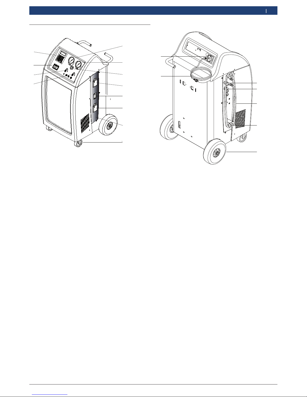
1
5
4
3
2
6
7
Fig. 2: Rear
1 Service quick-release coupling (high pressure)
2 Service quick-release coupling (low pressure)
3 Service hose (2,5m/5m)1)
4 Service hose mount
5 Rear wheels
6 Master switch
7 Power cord (socket)
1)
Depending on version ordered
3.4 Description of unit
4
6
5
1
2
3
8
7
9
10
12
11
Fig. 1: Front view
1 Valve high pressure (hp)
2 Valve low pressure (lp)
3 Printer
4 Display and control panel
5 Gauge low pressure (lp)
6 Gauge high pressure (hp)
7 Pressure gauge of internal refrigerant cylinder
8 Fresh oil bottle
9 UV dye bottle
10 Used oil bottle
11 Cover
12 Front wheels with locking brake
 Loading...