

Bosch ACS 500 Repair Instructions

ACS 500
Repair instructions
en
AC Service Unit

en2 ACS 500
1 689 975 197 (2006-09-22)
Robert Bosch GmbH

en 3ACS 500
Inhalt
1. Important information . . . . . . . . . . . . . . . . . . . . . . . . 4
2. Testing and resources
3. General and component overview
3.1 Overview .........................................................................................4
3.1.1 Electronic compartment ..............................................................
3.1.2 Cold chamber ................................................................................
3.2 Component overview ...................................................................
3.2.1 Valve block .....................................................................................
3.2.2 Processing unit .............................................................................
3.2.3 Actuation circuit board ................................................................
3.2.4 Refrigerant flask ............................................................................
4. Troubleshooting . . . . . . . . . . . . . . . . . . . . . . . . . . . . . 7
4.1 By function and fault messages ................................................ 7
4.2 By symptoms .................................................................................
5. Calibration and customer service menu . . . . . . . 10
5.1 Entering the calibration and customer service menu .........10
5.2 Calibration and customer service menu overview ..............
5.3 Description of calibration and customer service menu
5.3.1 Menu for updating the language database ...........................
5.3.2 Display menu for force and pressure sensor output
voltages .........................................................................................10
5.3.3 Menu for time and date setting ...............................................
5.3.4 Menu for changing language ...................................................
5.3.5 Parameter menu ..........................................................................
5.3.6 Menu for resetting system parameters ..................................
5.3.7 Menu for resetting counters .....................................................
5.3.8 Display menu for all counters ...................................................
5.3.9 Menu for entry of workshop address .....................................
5.3.10 Menu for setting the offset for the filling hoses. ..................
5.3.11 Menu for checking the control/display unit ...........................
5.3.12 Menu for calibration of force and pressure sensors ...........
. . . . . . . . . . . . . . . . . . . . . . . . 4
. . . . . . . . . . . . . 4
10
......10
10
11
11
11
11
11
11
11
11
11
11
6. Calibrating force and pressure sensors . . . . . . . 12
6.1 Calibrating force sensor ............................................................12
6.1.1 Refrigerant scale .........................................................................
6.1.2 Used oil, fresh oil or UV contrast medium scale .................
6.2 Calibrating the pressure sensor ..............................................
12
12
13
7. Updating firmware . . . . . . . . . . . . . . . . . . . . . . . . . . 13
4
5
5
5
6
6
6
8
8. Test
8.1 Control/display unit function test ............................................14
8.2 Checking the pressure switch .................................................
8.3 Check pressure sensor .............................................................
9. Repairs. . . . . . . . . . . . . . . . . . . . . . . . . . . . . . . . . . . . . 15
9.1 Opening and closing the ACS 500 .......................................15
9.1.1 Electronic compartment ............................................................
9.1.2 Cold chamber ..............................................................................
9.2 Replacing the actuation circuit board ....................................
9.3 Control/display unit ....................................................................
9.3.1 Replacing control/display unit .................................................
9.3.2 Checking control/display unit ..................................................
9.4 Replacing force sensor for refrigerant scale ........................
9.5 Replacing valve block ................................................................
9.6 Replacing the pressure sensor ..............................................
9.7 Replacing the vacuum pump ...................................................
9.8 Replace the preparation unit ...................................................
9.8.1 Removing processing unit .......................................................
9.8.2 Installing the processing unit ..................................................
9.9 Replacing the pressure switch ...............................................
9.10 Replacing force sensors for used oil, fresh oil and UV
. . . . . . . . . . . . . . . . . . . . . . . . . . . . . . . . . . . . . . . . 14
14
14
15
15
16
17
17
17
17
19
20
21
22
22
22
23
contrast medium scales ........................................................... 24
10. Hose system diagram . . . . . . . . . . . . . . . . . . . . . . . 25
11. Pneumatic circuit diagram
12. Electrical terminal diagram
12.1 General terminal diagram ........................................................27
12.2 Wiring harness terminal diagram ...........................................
12.2.1 Connection to actuation circuit board ..................................
12.2.2 Connection to valve block .......................................................
. . . . . . . . . . . . . . . . . . . 26
. . . . . . . . . . . . . . . . . . 27
28
28
28
Robert Bosch GmbH
1 689 975 197 (2006-09-22)

en
459790-3
HP
LP
10 11
4
1
2
3
5
6
7
8 9
1 2
3
4 5
6
7 8
9
R
1
3
4
a
R
1
3
4
a
U
V
.,
/
a
b
c
d
e
f
j
k
l
m
n
o
t
u
v
w
x
y
z
g
h
i
p
q
r
s
0
C
*
4 ACS 500
1. Important information
Installation and/or repairs may only be carried out by trained
and instructed Robert Bosch GmbH customer service staff
or organizations authorized by Robert Bosch GmbH.
Opening or modification of the units by unauthorized
persons will invalidate all warranty entitlements.
Electrical systems and equipment may only be commissioned
in proper condition (see Testing Technology Information
0108_084 for details). This requirement is met if, after
modification or repair (initial test), it is ensured that the
requirements of the electrical engineering regulations are
adhered to. To verify this tests should be performed, the
type and scope of which should be based on the measures
defined in the electrical engineering regulations (e.g.
in Germany BGV A3). In Germany, the type and scope
of the tests are described in VDE 0701/0702 Part 1. The
corresponding national regulations must be adhered to.
2. Testing and resources
#
General tool for electricians and mechanics
#
Digital multimeter
#
PC or Notebook (Windows 2000, XP)
#
9-pole Sub-D cabel (plug: male/female, wiring: 1:1) for
udating the firmware
#
Pipe sealant with PTFE (e. g. RODI-DOS PTFE from Würth).
#
Cleaning medium (e. g. brake cleaner)
#
Weights for calibration of scale:
−
10 kg
−
200 g
3. General and component overview
3.1 Overview
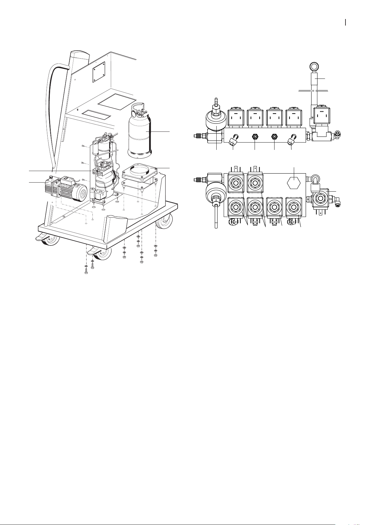
3.1.1 Electronic compartment
Fig. 1: Component overview in electronic compartment
1. Scale for UV contrast medium tank
2. Scale for used oil tank
3. Scale for fresh oil tank
4. Connection box with actuation circuit board
5. Valve block
6. Control/display unit
7. Low pressure (LP) and high pressure (HP) valve
8. LP manometer
9. HP manometer
10. Printer (accessory)
11. Connection line for firmware and language update
1 689 975 197 (2006-09-22)
Robert Bosch GmbH
en 5ACS 500
459
786-
4
1
2
3
4
1
3 4 5 6
7 8 9 10 11
12
459790-4
2
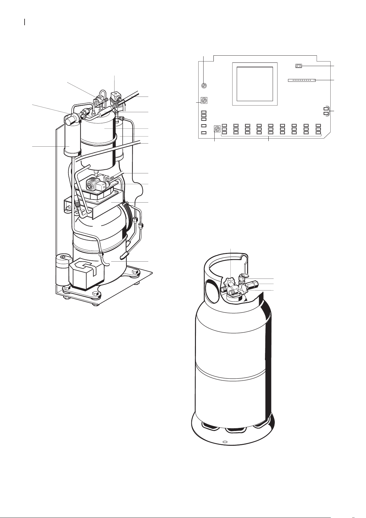
3.1.2 Cold chamber
3.2 Component overview
3.2.1 Valve block
Fig. 3: Valve block overview
1. Hose line for inlet and return
2. Solenoid valve for UV contrast medium injection phase
3. Solenoid valve (OUT L) for oil injection phase
4. Solenoid valve (OUT R) for filling phase
Fig. 2: Component overview in cold chamber
1. Refrigerant flask (reservoir)
2. Scale
3. Vacuum pump
4. Processing unit
5. Solenoid valves (OUT A) for recovery/recycling phase
6. Solenoid valves (OUT B) for vacuum phase
7. Pressure sensor
8. Connection to vacuum pump
9. Connection to processing unit
10. Connection to refrigerant flask
11. Connection to oil separator
12. Non-return valve
Robert Bosch GmbH
1 689 975 197 (2006-09-22)
en
45
97
86
-4
1
2
3
4
5
6
7
8
9
10
11
12
13
PROTECT.
PRINTER
COMPRESS.PUMP
J2
GND
V +18
GND
V +18
IN PMP
IN CMP
OUT HP
IN 7
IN 1
IN 3
IN 4
IN 6
IN 8
PUMPOUT 1OUT 3OUT 4OUT 6OUT 7OUT 8
LINE IN
200 mA T
F2
TERRA
TERRA
F1
F3
459786_6
1
2
3
5
4
6
7
BU
BN
BU
BN
YE/GN
BU
BN
YE/GN
BU
BN
YE/GN
BU
BN
YE/GN
BU
BN
YE/GN
BU
BN
YE/GN
BU
BN
YE/GN
BU
BN
YE/GN
BU
BN
YE/GN
BU
BN
YE/GN
YE/GN
YE/GN
1
2
3
4
459786_9
6
ACS 500
3.2.2 Processing unit
Changing the setting for the expansion valve (item 11)
!
can impair the function of the ACS 500.
3.2.3 Actuation circuit board
Fig. 5: Actuation circuit board overview
1. Printer power supply (accessory)
2. Control/display unit connection
3. Pressure switch power supply
4. ACS component power supply
5. Fuse F3 (10 AT) for mains connection
6. Fuse F2 (10 AT) for mains connection
7. Fuse F1 (200 mAT) for 12 Volt supply.
Fig. 4: Processing unit component overview
1. Inlet hose for processing system
2. Coarse filter
3. Moisture and oil separator
4. Oil separator
5. Inlet hose for refrigerant flask
6. Inlet hose for used oil tank
7. Solenoid valve (OUT S) for oil drain
8. Condenser with fan
9. Compressor
10. Filter and driver cartridge
11. Expansion valve
12. Non-return valve
13. Pressure switch
3.2.4 Refrigerant flask
Fig. 6: Refrigerant flask component overview
1. Safety valve (overpressure)
1 689 975 197 (2006-09-22)
2. Safety valve (for non-compressible gases)
3. LP fitting connection
4. HP fitting connection
Robert Bosch GmbH

ACS 500
4. Troubleshooting
4.1 By function and fault messages
Message Description Problem solving
Change filter.
Change vacuum pump.
Not enough R134a.
Please refill.
Used oil bottle full!
Not enough oil.
Please refill.
Not enough UV.
Please refill.
Internal pressure too high! Overpressure in refrigerant flask.
Printer failure! No paper loaded.
Internal tank full. Maximum permissible filling weight (10
Warning! Internal tank full. Refrigerant flask weight limit reached.
A/C system on
high pressure.
Recovery phase timeout. Maximum permissible time (240 min)
A/C system leaking! Pressure increase during pressure loss
Vacuum failure. Limit value of 100 mbar not reached
Vacuum not reached! The pressure in the vehicle A/C system
Calibration fault! Error in calibration of scale or scale de-
External tank empty or closed valve!
Refill phase timeout. Maximum permissible time for filling the
External tank empty! External flask for filling is empty.
Maintenance interval reached. Carry
out maintenance and reset counter (see
Operating instructions 1 689 979 953,
Section 7).
Insufficient refrigerant in internal refrigerant flask.
Overpressure in path after compressor.
Printer defective.
kg) of refrigerant flask reached.
Absolute pressure in vehicle A/C system
is greater than 1.6 bar
for evacuation of vehicle A/C system reached.
measurement (leak test) in vacuum phase.
10 minutes after start of vacuum phase.
is too high for oil or UV contrast medium injection.
fective.
Attempt to fill internal flask failed.
vehicle A/C system reached.
None
Top up refrigerant flask.
•
Control/display unit is defective. Replace control/display unit.
•
Empty used oil tank.
•
Force sensor for used oil scale is defective. Replace
•
force sensor.
Control/display unit is defective. Replace control/display unit.
•
Top up oil tank.•
Top up UV tank.•
Open shut-off valves and cocks on internal refrigerant flask.
•
Turn off ACS 500 and wait for 30 minutes. Then restart
•
the recovery/recycling phase.
Check non-return valve in inlet hose for internal refrige-
•
rant flask.
Check pressure switch.
•
Load new printer paper roll.
•
Replace printer.
•
Reduce quantity of refrigerant in refrigerant flask.
•
Check refrigerant scale with calibrating weight. Recali-
•
brate scale.
Reduce quantity of refrigerant in refrigerant flask.
•
Check refrigerant scale with calibrating weight. Recali-
•
brate scale.
Start and carry out recovery/recycling phase
Read pressure on manometer.
Pressure is present:
•
Solenoid valves for recovery/recycling phase do not
open:
Check solenoid valves.
$
Check solenoid valve actuation.
$
No pressure present:
•
Vehicle A/C system not tight
or
leak in processing unit
Scan connections for leakage.
$
Check solenoid valve for oil drain.
$
Check vehicle A/C system for leaks.
•
Check connections and condition of filling hoses.
•
Check connections and condition of quick release couplings.
•
Check vehicle A/C system for leaks.
•
Check connections and condition of filling hoses.
•
Check connections and condition of quick release couplings.
•
Start vacuum phase.
•
Check vehicle A/C system for leaks.
•
Recalibrate scale.
•
Replace scale.
•
Use full external flask.
•
Open low pressure (LP) and high pressure (HP) valve
•
Open valve cocks on refrigerant flask.
•
Check fill quantity in refrigerant flask and top up if neces-
•
sary.
Open low pressure (LP) and high pressure (HP) valve
•
Open valve cocks on refrigerant flask.
•
Check fill quantity in refrigerant flask and top up if necessary.
•
Obtain new flask with refrigerant.•
en 7
Robert Bosch GmbH
1 689 975 197 (2006-09-22)

en
8
4.2 By symptoms
Error pattern Cause Troubleshooting and correction
The digital display does not
light up.
The recovery and recycling phase
is slow or does not run at all.
The recovery and recycling phase
ends prematurely or not at all.
The gauge pressure rises after the
recovery and recycling phase.
The vacuum phase does not start. The vacuum pump does not start. Check fuses F2 and F3 on the control PCB.
The leakage test at the end of the
vacuum phase failed.
Filling in the filling phase is very
slow or is interrupted before the
set quantity has been filled.
The quantity filled does not match
the set amount.
Power supply interrupted. Check mains input voltage.
Check fuse F1 on the control printed circuit board.
Replace defective fuse.
The control / display unit or the control
printed circuit board is defective.
Wrong working position of the external
refrigerant cylinder when filling.
Low pressure valve and/or high pressure
valve is/are closed.
Flow in the hose lines may be faulty. Check external and hose lines, whether the sealing rings
Excess pressure in internal refrigerant
cylinder.
Compressor defective. Replace processing unit.
Filter and drier cartridge is saturated. Replace the filter and drier cartridge.
Ice in expansion valve due to aspirated
water.
Do not switch OUT A solenoid valves. Check relay on the control printed circuit board. If the re-
Incorrectly calibrated or faulty pressure
sensor.
Valve pistons for the recovery and recycling phase are leaking.
The valve pistons for the filling phase
are leaking.
Duration of the vacuum phase is too
short.
Leaking vehicle air conditioning system. Repair the vehicle's air conditioning system.
ACS is leaking internally. Check external filling hoses and their connections
Insufficient refrigerant in the internal refrigerant container.
Pressure in the internal refrigerant cylinder is too low.
Scale is not calibrated. Check scale with a known weight. If the value does not
Mechanical malfunction in the scale
movement.
Replace the control / display unit or control printed circuit
board.
Correct the working position of the external refrigerant cylinder (see operating instructions).
Open the valve in question.
have become deformed due to tightening of the hose lines,
thereby possibly blocking the flow of the refrigerant. Carefully loosen hose lines and tighten them again by hand. Replace misshapen seals if necessary.
Reduce pressure in the internal refrigerant cylinder by pulling the metal ring on the safety valve for excess pressure
(see Chap. 3.2.4, Item 1).
Heat expansion valve and replace all refrigerant from the
ACS with fresh refrigerant.
lay has blown, replace the control printed circuit board.
Check electrical connection to the solenoid valves.
Check connecting lines to the solenoid valves for continuity. Replace defective connecting line.
Connecting lines to the solenoid valves have been
swapped. Check connection against connection diagram /
wiring harness (see Chap. 12.2).
Connecting lines to control printed circuit board have
been swapped. Check connection against connection diagram / wiring harness (see Chap. 12.2).
Check pressure sensor (see Chap. 8.3).
Check condition (contamination, wear) of the valve pistons
in the valve block.
Caution: Close the shutoff valve on the internal refriger-
ant cylinder before testing.
Check condition (contamination, wear) of the valve pistons
in the valve block.
Check relay on the control printed circuit board. If the relay has blown, replace the control printed circuit board.
The vacuum pump is mechanically blocked. Replace vacuum pump.
Vacuum phase duration: approx. 30 min. for vehicles
(for larger systems, e.g. commercial vehicles, set a corre
spondingly longer vacuum time).
(e. g. are seals present?).
Check condition (contamination, wear) of the valve pistons
in the valve block.
Fill internal refrigerant cylinder with fresh refrigerant.
Optimum amount: approx. 7 kg.
Fill internal refrigerant cylinder with fresh refrigerant.
Optimum pressure: approx. 6-7 bar.
match, calibrate the scale (see Chap. 9.4.2).
Check whether the movement of the scale and the refriger-
ant cylinder is blocked mechanically by other components.
ACS 500
-
1 689 975 197 (2006-09-22)
Robert Bosch GmbH

ACS 500
Error pattern Cause Troubleshooting and correction
Compressor will not start. Power supply interrupted. Check fuses F2 and F3 on control PCB. Replace defective
White smoke escapes from the
vacuum pump.
Aspirated ambient air. Inspect the vehicle air conditioning system and ACS for
fuse.
Check relay on the control printed circuit board. If the re-
lay has blown, replace the control printed circuit board.
leaks and repair. Small quantities of smoke in the first minutes of the vacuum phase are permitted.
en 9
Robert Bosch GmbH
1 689 975 197 (2006-09-22)
 Loading...