

Bosch ACS 255 Original Instructions Manual
ACS 255
en
Original instructions
A/C service unit

Contents English
| ACS 255 | 3 en
1. Symbols used 4
1.1 In the documentation 4
1.1.1 Warning notices - Structure and
meaning 4
1.1.2 Symbols in this documentation 4
1.2 On the product 4
2. User information 5
2.1 User group 5
2.2 Agreement 5
2.3 Obligation of contractor 5
2.4 Safety Instructions 5
2.5 Safety devices 6
3. Product description 7
3.1 Application 7
3.2 Delivery specification 7
3.3 Description of unit 7
3.3.1 Human Machine Interface (HMI) 8
3.3.2 Scale for refrigerant tank 8
3.3.3 Oil bottles 8
3.3.4 Quick couplers 9
3.3.5 Brakes 9
3.3.6 Power cable and master switch 9
3.4 Description of function 9
4. Commissioning 10
4.1 Removing the transport packaging 10
4.2 Before turning on for the first time 10
4.3 Powering on the ACS 255 11
4.4 Changing the system defaults 11
4.5 Filling the internal refrigerant
tank 12
4.6 Viewing system information 12
5. Troubleshooting 13
6. Program description 14
6.1 ACS 255 operating modes 14
6.2 Preparations for A/C service 14
6.3 Configuring the custom database 14
6.3.1 Adding new vehicle details to the
vehicle database 14
6.3.2 Editing vehicle details in the custom
database 14
6.3.3 Deleting vehicle details from the
custom database 14
6.3.4 Viewing custom database information 14
6.3.5 Transferring the custom database
from one ACS 255 to another 14
6.4 Accessing the custom database 14
6.5 Automatic mode 15
6.5.1 Overview of automatic mode 15
6.5.2 Selecting the vehicle from the
custom database 15
6.5.3 Setting custom parameters 15
6.6 Manual mode 15
6.6.1 Overview of manual mode 15
6.6.2 Recovery 16
6.6.3 Vacuuming phase 16
6.6.4 Oil recharge phase 16
6.6.5 Recharge phase 16
6.7 Performing service in manual mode 16
6.8 Additional services 17
6.8.1 Refrigerant top up 17
6.8.2 Hose drain 17
6.8.3 A/C performance test 17
7. Maintenance 18
7.1 Spare and wearing parts 18
7.2 Refilling the refrigerant tank 18
7.3 Service record 18
7.3.1 Viewing the last three vehicle A/C
service reports 18
7.3.2 Last self test 18
7.3.3 Last five errors during vehicle A/C
service 18
7.4 Vacuum pump oil change 18
7.5 Replacing the filter drier 19
7.6 Replacing the inline filters 19
7.7 Self test 20
7.8 Firmware update 20
7.9 Resetting factory settings 20
8. Decommissioning 21
8.1 Disposal of electronic items 21
8.2 Disposal of LCD display, refrigerants,
lubricants and oils 21
8.3 Disposal of filter drier 21
8.4 Electromagnetic compatibility (EMC) 21
9. Technical data 21
F 002 DG9 432 2014-12-19| Bosch Limited
4 | ACS 255 | Symbols useden
1. Symbols used
1.1 In the documentation
1.1.1 Warning notices - Structure and meaning
Warning notices warn of dangers to the user or people
in the vicinity. Warning notices also indicate the consequences of the hazard as well as preventive action.
Warning notices have the following structure:
Warning
symbol
The key word indicates the likelihood of occurrence and
the severity of the hazard in the event of non-observance:
Key word Probability of
DANGER
WARNING
CAUTION
KEY WORD – Nature and source of hazard!
Consequences of hazard in the event of failure to observe action and information given.
¶ Hazard prevention action and information.
occurrence
Immediate impending
danger
Possible impending
danger
Possible dangerous
situation
Severity of danger if instructions not observed
Death or severe injury
Death or severe injury
Minor injury
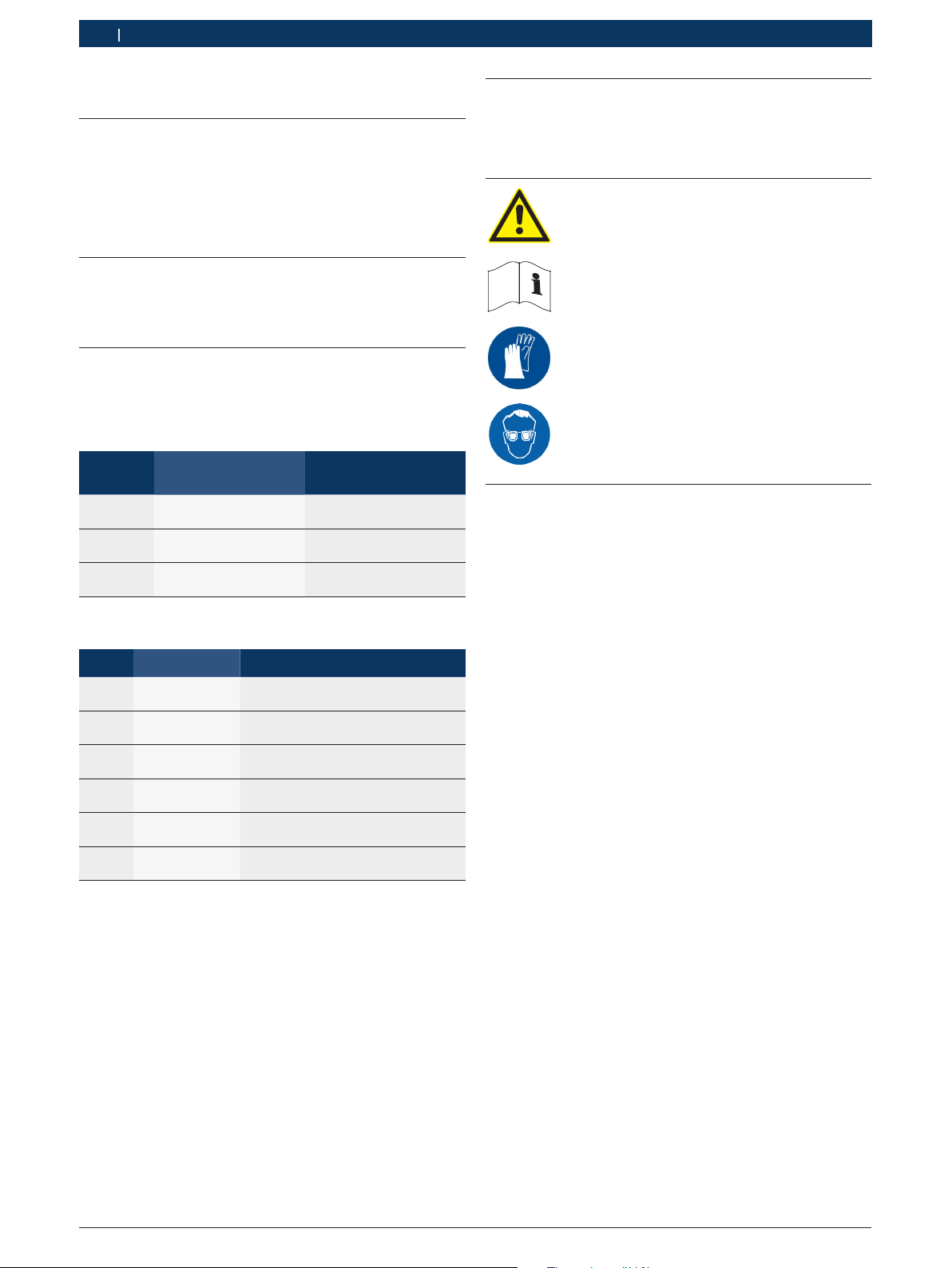
1.2 On the product
! Observe all warning notices on products and ensure
they remain legible.
Caution!
Contact with the refrigerant can cause
blindness and severe injuries.
¶ Read this operating manual and all
technical documentation for the used
components.
¶ Wear protective gloves.
¶ Wear protective goggles.
1.1.2 Symbols in this documentation
Symbol Designation Explanation
!
i
1.
2.
e
"
Attention Warns about possible property dam-
Information Practical hints and other useful in-
Multi-step
operation
One-step operation
Intermediate result
Final result There is a visible final result on com-
age.
formation.
Instruction consisting of several
steps.
Instruction consisting of one step.
An instruction produces a visible intermediate result.
pletion of the instruction.
F 002 DG9 432 2014-12-19| Bosch Limited
User information | ACS 255 | 5
en
2. User information
2.1 User group
The product may be used by skilled and instructed
personnel only. Personnel scheduled to be trained, familiarized, instructed or to take part in a general training course may only work with the product under the
supervision of an experienced person.
All work conducted on pressurized equipment may be
performed by persons with sufficient knowledge and
experience in using pressurized devices and, also be
aware of the risks involved in the use of pressurized
devices.
2.2 Agreement
Your use of the product means that you accept the following conditions:
Copyright
Software and data are the property of Bosch Limited,
hereafter denoted as Bosch, or its suppliers and are
protected against unauthorized reproduction under
copyright laws, international contracts and other national legal provisions. Copying and selling of data
and software or any other part thereof is prohibited
and punishable by law. In the event of violations,
Bosch Limited reserves the right to proceed with criminal prosecution and to claim for damages.
Liability
All data in this program is based - where possible - on
manufacturer and importer details. Bosch does not accept liability for the correctness and completeness of
software and data; liability for damage caused by faulty
software and data is ruled out. Whatever the event,
Bosch liability is restricted to the amount for which the
customer actually pays for this product. This disclaimer
of liability does not apply to damages caused by intent
or gross negligence on the part of Bosch.
2.3 Obligation of contractor
The contractor is obliged to ensure that all measures
geared towards the prevention of accidents, industrial
diseases, labor-related health risks are taken and measures towards making the workplace fit for people to
work in are carried out.
The contractor is bound to ensure that all electrical
equipment and operating material is set up, modified
and maintained by skilled electricians only or under the
guidance and supervision of a skilled electrician in accordance with electrical engineering principles.
Furthermore, the contractor must ensure that all electrical equipment and operating material is operated in
keeping with electrical engineering principles.
If a piece of electrical equipment or operating material
is found to be defective, i.e. it does not or no longer
complies with electrical engineering principles, the contractor must ensure that the fault is rectified immediately and, in the event that imminent danger exists, also
ensure that the electrical equipment or the electrical
operating material is not used.
2.4 Safety Instructions
All safety instructions are to be read thoroughly before
using the Bosch product and they must be observed.
R Avoid the refrigerant coming into contact with the
skin. The low boiling point of the refrigerant (approximately -30 °C at atmospheric pressure) can cause
frostbite. In case of contact with the skin, remove
wet clothing immediately and rinse the affected area
of skin with plenty of water.
Do not breathe in refrigerant or oil vapors.
The vapors can irritate the eyes and the
breathing passage of the nose. If liquid
refrigerant/oil gets into the eyes, rinse the
eyes thoroughly with water for 15 minutes.
Then, seek medical attention, even if the
eyes do not hurt.
Warranty
Any use of non-approved hardware and software will
result in a modification to our product and thus to
exclusion of any liability and warranty, even if the hardware or software has in the meantime been removed or
deleted. No changes may be made to our products. Our
products may only be used in combination with original
accessories and original service parts. Failing to do so,
will render null and void all warranty claims.
R Before the ACS 255 is connected to the vehicle A/C
system or to an external refrigerant tank, ensure that
the quick couplers do not leak. Use only external
refrigerant tanks that are fitted with safety valves
and approved in accordance with the applicable
standards.
R Before turning off the ACS 255, ensure that all the
service phases are complete. This prevents refrigerant from escaping into the environment.
F 002 DG9 432 2014-12-19| Bosch Limited
6 | ACS 255 | User informationen
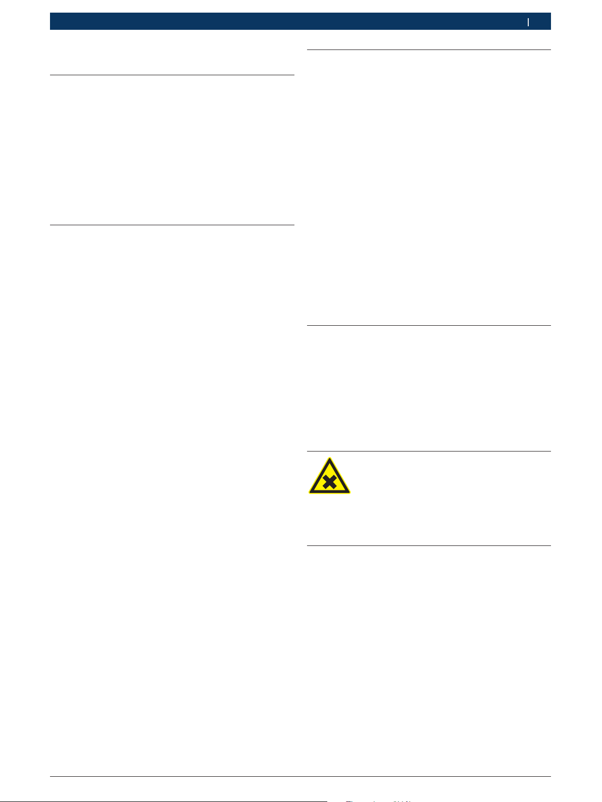
Do not use compressed air with R134a.
Some mixtures of air and R134a are highly
flammable at high pressure. These mixtures
are potentially hazardous and can cause
fires or explosions resulting in damage to
property and injury to persons.
R Refrigerant extracted from the vehicle A/C system
might be contaminated with moisture, lubricant, dirt
and traces of other gases.
R The ACS 255 does not have any refrigerant identifier
system. If refrigerants other than R134a are used, it
might lead to contamination.
R R134a is colorless, odorless and heavier than air. It
expels oxygen and can flow into repair pits. If the
refrigerant escapes, there is a risk of suffocation in
poorly ventilated rooms or repair pits.
R R134a may not be used in environments with a risk
of explosion. Fire, naked flames and smoking are
prohibited. No welding or soldering is allowed. High
temperatures and UV radiation can cause R134a to
chemically separate. The resulting products cause
coughs and nausea.
R R134a may not be mixed with other refrigerants.
Mixing refrigerants can cause damage to the vehicle
A/C system.
R The ACS 255 must always be monitored during op-
eration. Do not leave the ACS 255 unattended when
it is switched on.
R Vehicle A/C service, using the ACS 255, must be pre-
pared and carried out in such a way that the vehicle
A/C circuit is not opened (for example, radiator or
engine removal).
R The ACS 255 should be positioned with all four
wheels on a flat, vibration-free surface to ensure
correct operation of the load sensors. The ACS 255
can be prevented from rolling away by applying the
brake.
R The ACS 255 must always be transported in a verti-
cal position. Do not invert the ACS 255.
R There are no additional safety provisions for protect-
ing the ACS 255 unit against damage in the event of
natural calamities like earthquakes, fires, floods etc.
R Except for maintenance work, do not remove any
pressurized equipment inside the
ACS 255 unit. Adhere to the national laws or regulations for ensuring safety of pressurized equipment.
R We recommend that calibration of load sensors be
done at least once every year. Contact customer
service for calibration of load sensors.
R The ACS 255 must be regularly inspected by service
personnel or the approved authorities to ensure
safety of the unit.
Warning - Risk of frostbite in the event of
refrigerant leakage!
If refrigerant escapes, there is a risk of frostbite to the hands and body.
¶ Wear protective goggles.
¶ Wear protective gloves.
¶ Ensure that the HP and LP hoses are not
damaged.
¶ Ensure that the quick couplers are tightly
fixed to the hoses.
Warning - Risk of frostbite during removal
of service hoses!
If refrigerant escapes, there is a risk of
frostbite to the hands and body.
¶ Carefully disconnect service hoses as all
hoses can contain pressurized
refrigerant.
R Only connect to a properly grounded electrical
outlet.
R Do not attempt to shut off the valves on the R134a
tank when the ACS 255 is in operation.
R For the purposes of safety, it is recommended to use
an Earth Leakage Circuit Breaker (ELCB) with the
following specifications:
Parameter Specification
Rated voltage 230 VAC +/- 10%
Rated frequency 50/60 Hz
Rated current 10 A
Rated trip current 30 mA
Tripping curve C
2.5 Safety devices
R Pressure switch - Switches the compressor off if the
normal operating pressure is exceeded.
R Safety valve: Operates when the design pressure is
exceeded.
R Fuse: Interrupts excessive current flow into the
ACS 255.
F 002 DG9 432 2014-12-19| Bosch Limited
Product description | ACS 255 | 7
1
2
3
en
3. Product description
3.1 Application
The ACS 255 is used to perform the following basic
services for passenger car A/C systems in manual or
automatic mode:
R Refrigerant recovery
R Oil recharge
R Vacuuming and leak tests
R Refrigerant recharge
The ACS 255 should be used with car A/C systems that
use R134a.
3.2 Delivery specification
Description
ACS 255
Hose - HP
Hose - LP
Quick coupler - HP
Quick coupler - LP
Can assembly - Used oil
Can assembly - Fresh oil
Operating instructions
Adapter for filling internal refrigerant tank
3.3 Description of unit
15
14
13
459897_159Nkv
12
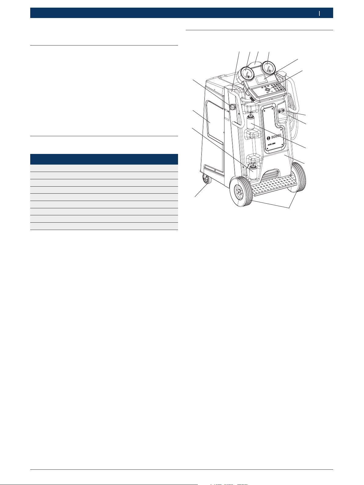
Fig. 1: Front view
1 Handle (x 2)
2 HP gauge
3 Status and warning light
4 LP gauge
5 LCD
6 Keypad
7 LP hose
8 HP hose
9 Fresh oil bottle
10 Front panel
11 Front wheels
12 Rear wheel (x 2)
13 Used oil bottle
14 Left-hand side panel
15 Master switch
4
5
6
7
8
9
10
11
F 002 DG9 432 2014-12-19| Bosch Limited
8 | ACS 255 | Product descriptionen
1
9
2
3
8
4
459897_112Nkv
7
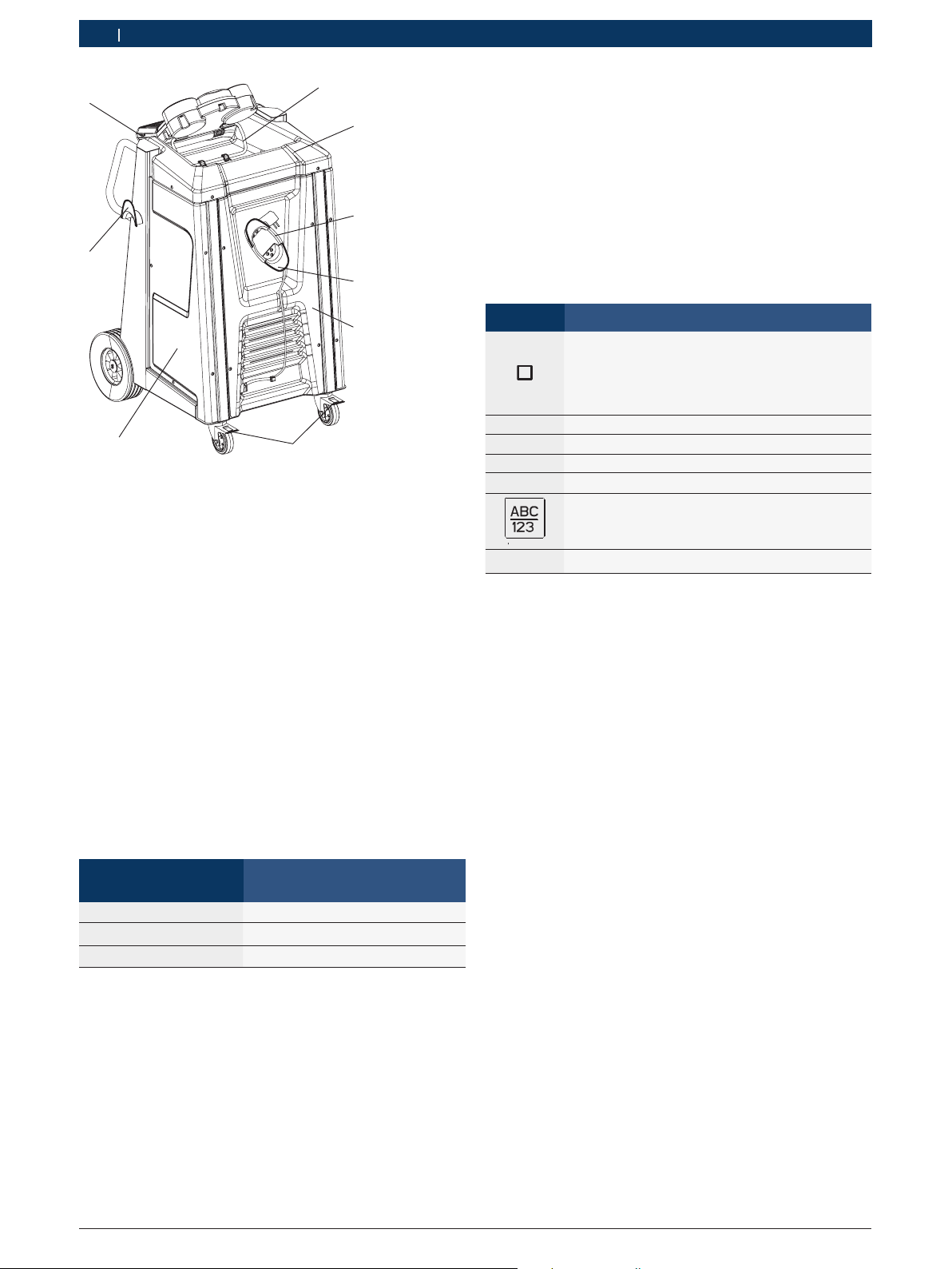
Fig. 2: Rear view
1 HMI support
2 Painel superior
3 Power cable
4 Cable holder
5 Rear panel
6 Brakes
7 Right-hand side panel
8 Hose holder
9 USB port
6
5
3.3.1 Human Machine Interface (HMI)
The HMI consists of:
R Pressure gauges - The pressure during the service is
displayed on the gauges.
R Status and warning lights - The status of service
and disruptions during service are indicated by the
status and warning light.
R Keypad - The selection of service menu options and
service parameters can be done via the keypad. The
alphanumeric input keys can be used to enter letters
and special characters in input fields. In an input
field, pressing a key several times in succession
displays all the characters it can be used for (upper
case letters, special characters).
i The alphabetical entries can be made in upper case
only.
Keys Description
c
o or u Navigate up or down
v or z
E
C
Function keys,
The function keys are assigned various functions in the ACS 255 software. The functions of
the keys are specified in the soft key bar of the
ACS 255 software.
Navigate right or left
Enter
Clear
Switch between numeric and alphabetical entry
Display system information
i
R USB port - Firmware updates can be performed by
plugging the USB disk into the USB port.
3.3.2 Scale for refrigerant tank
The quantity of refrigerant charged into the vehicle A/C
system is controlled by a scale mounted beneath the
refrigerant tank.
3.3.3 Oil bottles
! Do not apply excessive force while detaching or at-
taching the oil bottles.
Color indicated by the
status and warning light
Red Error/Warning
Blinking green Service in progress
Static green Service complete
Status of service
R LCD - The menu options and status of service are
displayed on the LCD.
F 002 DG9 432 2014-12-19| Bosch Limited
 Loading...