

Page 1

Access Management System
AMS Configuration and Operation
en
Software manual
Page 2

Page 3

Access Management System Table of contents | en 3
Table of contents
1
2
3
4
5
Using Help 6
About this documentation 8
AMS System overview 9
Licensing the system 10
Configuring the calendar 12
5.1 Defining Special days 12
5.2 Defining Day models 14
5.3 Defining Time models 15
6
Configuring Divisions 18
6.1 Assigning Divisions to devices 18
6.2 Assigning Divisions to operators 19
7
8
9
Configuring the IP addresses 20
Using the Device Editor 21
Configuring areas of access control 23
9.1 Configuring areas for vehicles 24
10
Configuring intrusion areas and panels 26
10.1 Connecting the access control system to the intrusion panels 26
10.1.1 Step 1: Connecting to the RPS API 27
10.1.2 Step 2: Configuring the panel connections 27
10.2 Creating authorization profiles for panels 28
10.3 Assigning panel authorization profiles to cardholders 29
11
Configuring operators and workstations 30
11.1 Creating the workstations 30
11.2 Creating workstation profiles 31
11.3 Assigning workstation profiles 32
11.4 Creating user (operator) profiles 32
11.5 Assigning user (operator) profiles 33
11.6 Setting passwords for operators 34
12
Configuring cards 36
12.1 Card Definition 36
12.1.1 Creating and Modifying 36
12.1.2 Activating / Deactivating card definitions 37
12.1.3 Creating card data in the dialog manager 38
12.2 Configuring card codes 39
13
Configuring the controllers 42
13.1 Configuring MACs and RMACs 42
13.1.1 Configuring a MAC on the DMS server 42
13.1.2 Preparing MAC server computers to run MACs and RMACs 43
13.1.3 Configuring a MAC on its own MAC server 44
13.1.4 Adding RMACs to MACs 45
13.1.5 Adding further MAC/RMAC pairs 47
13.1.6 Using the MAC installer tool 48
13.2 Configuring the LACs 50
13.2.1 AMC parameters and settings 51
14
Configuring Entrances 67
14.1 Entrances - introduction 67
14.2 Creating entrances 67
14.3 Configuring AMC terminals 71
Bosch Security Systems
Software manual
2021-03 | 3.0.1.1 |
Page 4

4 en | Table of contents Access Management System
14.4 Predefined signals for door models 77
14.5 Special entrances 82
14.5.1 Elevators (DM07) 82
14.5.2 Door models with intruder alarms (DM14) 86
14.5.3 DIPs and DOPs (DM15) 90
14.5.4 Mantrap door models 91
14.6 Doors 93
14.7 Readers 96
14.7.1 Configuring random screening 105
14.8 Access by PIN alone 105
14.9 AMC extension boards 107
15
Custom Fields for personnel data 111
15.1 Previewing and editing Custom fields 111
15.2 Rules for data fields 113
16
Configuring Threat Level Management 114
16.1 Concepts of Threat Level Management 114
16.2 Overview of the configuration process 114
16.3 Configuration steps in the device editor 115
16.3.1 Creating a threat level 115
16.3.2 Creating a Door security profile 115
16.3.3 Creating a Reader security profile 116
16.3.4 Assigning door and reader security profiles to entrances 117
16.3.5 Assigning a threat level to a hardware signal 118
16.4 Configuration steps in System data dialogs 119
16.4.1 Creating a Person security profile 119
16.4.2 Assigning a Person security profile to a Person Type 119
16.5 Configuration steps in Personnel data dialogs 120
17
18
Configuring Milestone XProtect to use AMS 121
Defining access authorizations and profiles 123
18.1 Creating access authorizations 123
18.2 Creating access profiles 123
19
Creating and managing personnel data 125
19.1 Persons 125
19.1.1 Card control or Building control options 127
19.1.2 Extra info: Recording user-defined information 128
19.1.3 Recording signatures 128
19.1.4 Enrolling fingerprint data 128
19.2 Companies 130
19.3 Cards: Creating and assigning credentials and permissions 130
19.3.1 Assigning cards to persons 131
19.3.2 Printing badges 132
19.3.3 Authorizations tab 133
19.3.4 Other data tab: Exemptions and special permissions 134
19.3.5 Authorizing persons to set Office mode 135
19.3.6 Smartintego tab 136
19.3.7 Creating an Alert card 137
19.4 Temporary cards 138
19.5 PIN codes for personnel 139
19.6 Blocking access for personnel 140
2021-03 | 3.0.1.1 |
Software manual
Bosch Security Systems
Page 5

Access Management System Table of contents | en 5
19.7 Blacklisting cards 142
19.8 Editing multiple persons simultaneously 143
19.8.1 Group authorizations 144
19.9 Changing the Division for persons 145
19.10 Setting the area for persons or vehicles 146
19.10.1 Procedure for resetting the location of all cardholders and vehicles 146
19.11 Customizing and printing forms for personnel data 147
20
Managing visitors 148
20.1 Visitor data 148
21
Managing parking lots 153
21.1 Authorizations for several park zones 153
21.2 Parking lot report 154
21.3 Extended Car Park management 154
22
Managing guard tours and patrols 156
22.1 Defining guard tours 156
22.2 Managing patrols 157
22.3 Tour monitoring (formerly path control) 158
23
24
Random screening of personnel 160
Using the Event Viewer 162
24.1 Setting filter criteria for time relative to the present 162
24.2 Setting filter criteria for a time interval 162
24.3 Setting filter criteria irrespective of time 163
25
Using reports 164
25.1 Reports: master data 164
25.1.1 Reporting on vehicles 166
25.2 Reports: system data 167
25.3 Reports: authorizations 168
26
Operating Threat Level Management 170
26.1 Triggering and cancelling a threat alert via UI command 170
26.2 Triggering a threat alert via hardware signal 171
26.3 Triggering a threat alert via Alert card 171
27
Backup and Restore 172
27.1 Backing up the system 172
27.2 Restoring a backup 173
27.2.1 Restoring RMACs into a new installation 175
Glossary 176
Bosch Security Systems
Software manual
2021-03 | 3.0.1.1 |
Page 6
6 en | Using Help Access Management System
1 Using Help
How to use this help file.
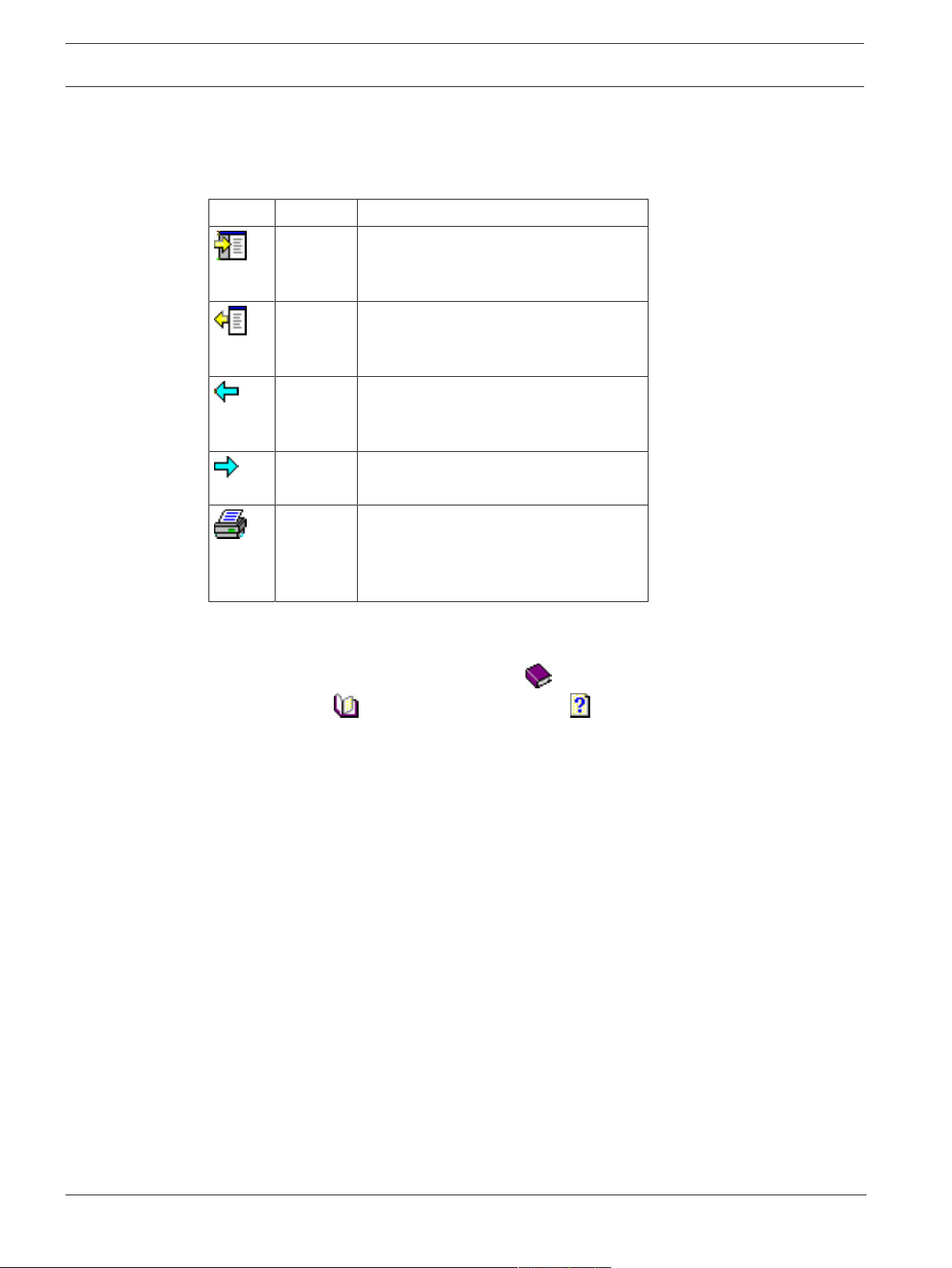
Tool bar buttons
Button Function Description
Hide Click this button to hide the navigation
pane (Contents, Index and Search tabs).
leaving only the help pane visible.
Show When the Hide button is clicked it is
replaced by the Show button. Click this
button to reopen the Navigation pane.
Back Click this button to move back through
the chain of topics most recently
viewed.
Forward Click this button to move forward again
through the same chain of topics
Print Click this button to print. Choose
between “Print the selected topic,” and
“Print the selected heading and all
subtopics”.
2021-03 | 3.0.1.1 |
Tabs
Contents This tab displays a hierarchical table-of-
contents. Click a book icon to open it
and then click on a topic icon to view
the topic.
Index This tab displays an index of terms in
alphabetical order. Select a topic from the
list or type in a word to find the topic(s)
containing it.
Search Use this tab to find any text. Enter text in the
field and then click button: List Topics to
find topics that contain all the words
entered.
Resizing the help window
Drag the corner or edge of the window to the desired size.
Further conventions used in this documentation
– Literal text (labels) from the UI appears in bold.
E.g. Tools, File, Save As...
– Sequences of clicks are concatenated using the > character (the greater-than sign).
E.g. File > New > Folder
– Changes of control-type (e.g. menu, radio-button, check box, tab) within a sequence are
indicated just before the label of the control.
E.g. Click menu:Extra>Options>tab:View
– Key combinations are written in two ways:
Software manual
Bosch Security Systems
Page 7

Access Management System Using Help | en 7
– Ctrl+Z means hold down the first key while pressing the second
– Alt, C means press and release the first key, then press the second
– The functions of icon buttons are added in square brackets after the icon itself.
E.g. [Save]
Bosch Security Systems
Software manual
2021-03 | 3.0.1.1 |
Page 8

8 en | About this documentation Access Management System
2 About this documentation
This is the main software manual for the Access Management System.
It covers the use of the main dialog manager program, hereafter referred to as AMS
– The configuration of an access control system in AMS .
– The operation of the configured system by system operators.
Related documentation
The following are documented separately:
– The installation AMS and its auxiliary programs.
– The operation of AMS - Map View.
2021-03 | 3.0.1.1 |
Software manual
Bosch Security Systems
Page 9

Access Management System AMS System overview | en 9
3 AMS System overview
Access Management System is a powerful, pure access control system, which performs solo or
in concert with BVMS, the Bosch flagship video management system.
Its power stems from its unique balance of leading-edge and proven technologies:
– Designed for usability: practical user interface with drag-and-drop Map View, and
streamlined biometric enrollment dialogs.
– Designed for data security: supporting the latest standards (EU-GDPR 2018), operating
systems, databases and encrypted system interfaces.
– Designed for resilience: middle-layer main access controllers provide automatic failover
and replenishment of local access controllers in case of network failure.
– Designed for the future: regular updates and a pipeline full of innovative enhancements.
– Designed for scalability: offering low to high entry levels.
– Designed for interoperability: RESTful APIs, with interfaces to Bosch video management,
event handling and specialized partner solutions.
– Designed for investment-protection: allowing you to build on, but boost the efficiency of,
your installed access-control hardware.
Bosch Security Systems
Software manual
2021-03 | 3.0.1.1 |
Page 10
10 en | Licensing the system Access Management System
i
4 Licensing the system
Prerequisites
– The system has been installed successfully.
– You are logged onto the AMS server computer, preferably as Administrator.
Procedure for purchased licenses
Prerequisites: You have purchased licenses based on the computer signature of this
computer. Contact your sales representative for instructions.
Dialog path: Configuration > Licenses
1. Log onto AMS, the Access Management System.
2. On the License tab, click the Start License Manager button.
– Effect: The License Manager dialog box is displayed.
3. Select the check boxes for the software package, the features, and the expansions that
you have ordered. For the expansions, enter also the number of units required.
4. Click the Activate… button.
– Effect: The License Activation dialog box is displayed containing your computer
signature.
5. Write down the computer signature or copy and paste it into a text file.
6. On a computer with Internet access, enter the following URL into your browser:
https://activation.boschsecurity.com
If you do not have an account to access the Bosch License Activation Center, either
create a new account and log on (recommended), or click the link to activate a new
license without logging on. Note that for SMA (software maintenance agreement) licenses
an account is always required. An account has the further advantage of keeping track of
all your activations for future reference.
Follow the instructions on the website to obtain the License Activation Key.
7. Return to the software. In the License Activation dialog box, type or paste in the License
Activation Key obtained from the Bosch License Activation Center and click the Activate
button.
– Effect: The software packages are activated for the computer.
Notice!
Effects of hardware and software changes
Changes to the hardware of the your server may invalidate your license and cause the
software to stop functioning. Please check with technical support before making changes to
the server.
Procedure for Demonstration Mode
Demonstration Mode licenses all system features for a limited period. Use Demonstration
Mode only in non-production environments to try out features before purchasing them.
1. Log onto the Access Manager
2. Navigate to Configuration > Licenses
3. Click the button Activate Demo Mode
4. Verify that the features are listed in the Licenses dialog window.
Demonstration mode is activated for 5 hours. Note that the expiration time is displayed near
the top of the Licenses dialog, and in the title bar of most dialog windows.
2021-03 | 3.0.1.1 |
Software manual
Bosch Security Systems
Page 11

Access Management System Licensing the system | en 11
Bosch Security Systems
Software manual
2021-03 | 3.0.1.1 |
Page 12
12 en | Configuring the calendar Access Management System
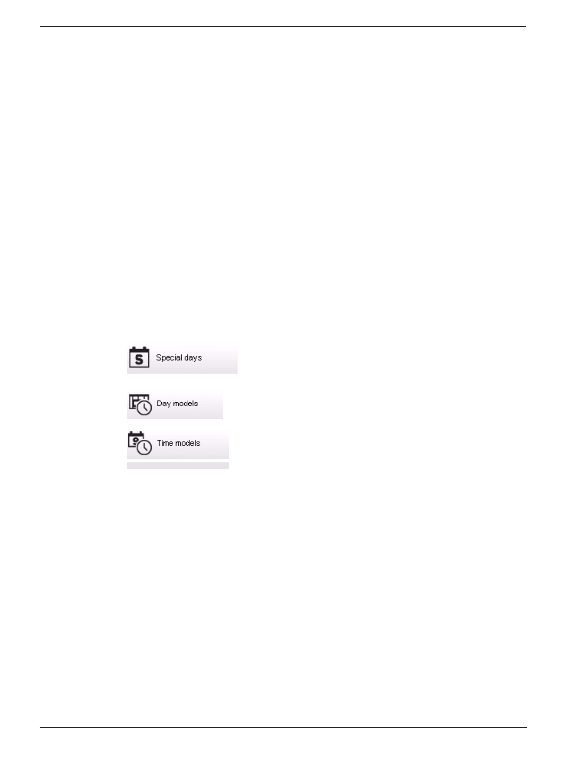
5 Configuring the calendar
The scheduling of access control activities is governed by time models.
A time model is an abstract sequence of one or more days, each of which is described by a
day model.
Time models control activities when they are applied to the underlying calendar of the access
control system.
The calendar of the access control system is based on the calendar of the host computer’s
operating system, but amplifies it with special days that are freely defined by the
administrator of the access control system.
Special days can be fixed to a particular date in the calendar or defined relative to a cultural
event, such as Easter. They can be recurring or not.
The configuration of an effective calendar for your access control system consists of the
following steps.
1. Define the special days of the calendar that applies to your location.
2. Define day models that describe the active and inactive periods of each type of day. For
instance, the day model for a public holiday will be different from that of a normal
working day. Shift work will also effect the type and number of day models you require.
3. Define time models consisting of one or more day models.
4. Assign time models to cardholders, authorizations and entrances.
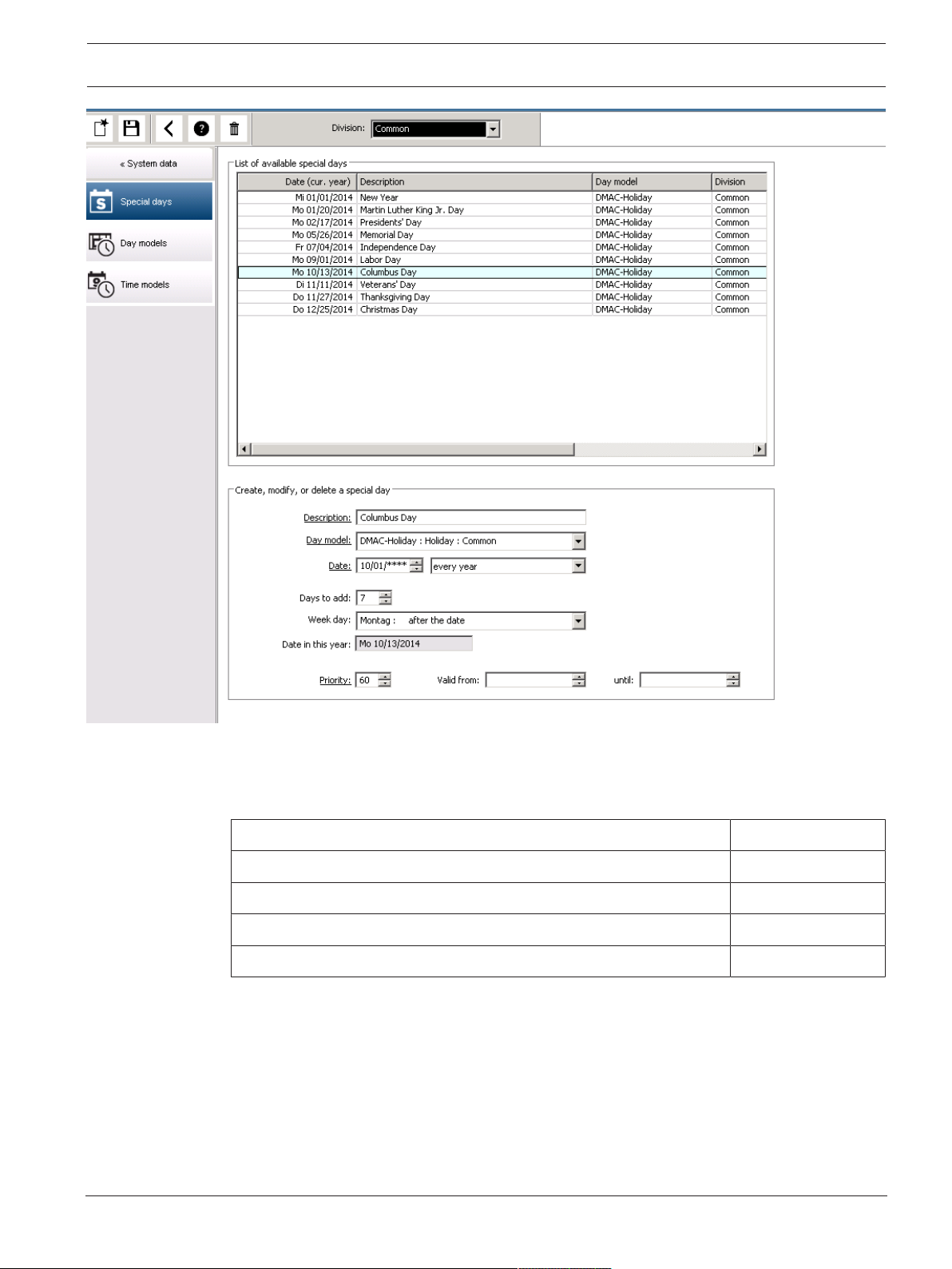
5.1 Defining Special days
When this is opened, a list appears in the top list field of the dialog containing all specified
holidays. Please note that all holiday dates shown relate only to the current year. However, the
calendar is updated from year to year in accordance with the data entered.
Beneath the list there are different dialog fields for the creation of new special days and for
the change or deletion of existing special days. To add a new special day, at least three of
these input fields must contain data. First a description and a date must be entered in the
respective fields. Thirdly the class to which this special day belongs must be selected from the
appropriate selective list.
2021-03 | 3.0.1.1 |
Software manual
Bosch Security Systems
Page 13
Access Management System Configuring the calendar | en 13
The date is specified in several steps. First of all, a base date is entered in the Date field. At
this point the date describes an event in the current year. If the user now specifies the
frequency of a periodic return in the selection list next to the date field, the parts of the date
set by the periodicity are replaced by "wildcards" (*).
once __.__.____
once per year __.__.****
once per month for a period of a year __.**.____
once per month in every year __.**.****
depending on Easter **.**.****
Holidays that depend on Easter are not specified with their date, but with the difference in
days from Easter Sunday. The date of the Easter Sunday in the current year is indicated in the
Date within this year field , and the variance of this date is entered or selected in the Days to
add field.The maximum number of days is 188, so with adding or subtracting you can define
every day of the year.
The other data, e.g. the week day of the holiday, are optional. Please note that the week day
list is determined by the regional settings of the operating system (OS). This leads
unavoidably to mixed-language displays where the languages of the access control system and
the OS differ.
Bosch Security Systems
Software manual
2021-03 | 3.0.1.1 |
Page 14
14 en | Configuring the calendar Access Management System
i
The assignment of a validity period is also optional. If no duration is specified, the default
settings make validity unlimited from the input date.
A priority can also be set. The priority, rising from 1 to 100, defines which holiday shall be
used. If two holidays fall on the same date, the holiday with the higher priority ranges first. In
case of equal priorities it is undefined which holiday will be used.
Holiday with the priority “0” are deactivated and will not be used.
The dialog Time Models displays only the active holidays, i.e. with a priority greater than 0.
Notice!
A time model of the division “Common” can only use holidays which are assigned to the
division “Common”.
A time model of a specific division “A” can only use holidays which are assigned to the
division “A”.
It is not possible to mix holidays between divisions, i.e. every division can use only the
specific holidays which are assigned to it in its specific time model.
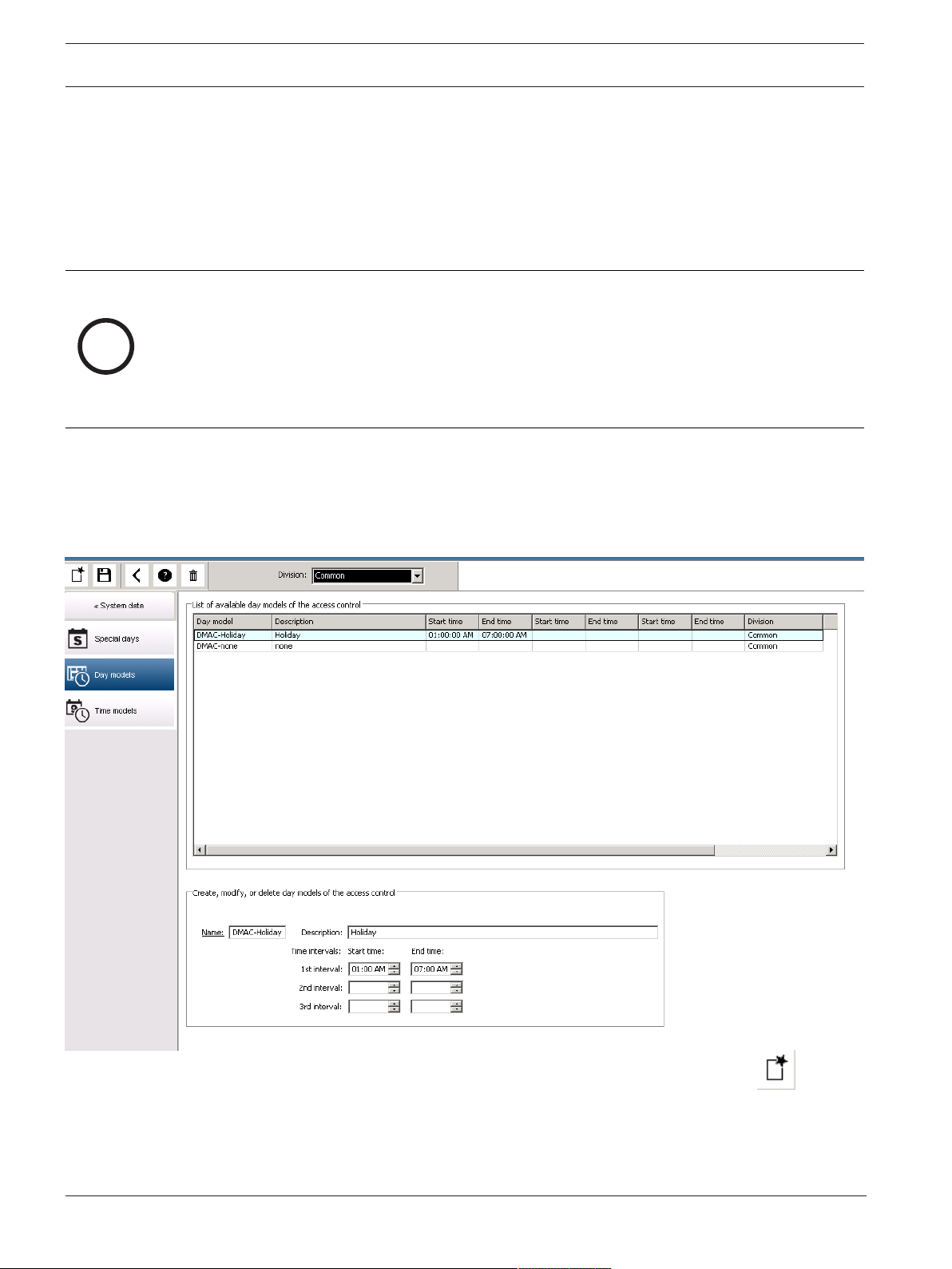
5.2 Defining Day models
Day models define a pattern for any day. They can have up to three time intervals.
Once the dialog is started, all existing day models are displayed.
2021-03 | 3.0.1.1 |
Use the dialog to define or modify model name, descriptions and intervals. The icon
starts a new model.
Software manual
Bosch Security Systems
Page 15
Access Management System Configuring the calendar | en 15
i
Start and End times for an interval are entered in hours and minutes. As soon as such a time is
reached the interval is activated or deactivated respectively. In order to mark these times
more clearly as delimiters, the list pane displays them with seconds (always 00). For example,
an authorization in a time model which contains an interval from 8:00 AM to 3:30 PM allows
access from 8:00 AM to 3:30 PM but prevents access at 3:30:01 PM.
Start and end times are subjected to logical checks when they are entered, for instance a start
time must be smaller than its corresponding end time.
One consequence of this is that no interval may extend over midnight, but has to be split at
that point:
1st Interval from: ... to: 12:00 AM
Following Interval from: 12:00 AM to: ...
With the exception of midnight (12:00 AM) no overlaps are allowed between the interval
delimiters of a single day model. Note, this precludes the entering of the same time for the
end of one and the beginning of the next interval.
Exception: A 24 hour interval nevertheless has start and end times both set to 12:00 AM.
Notice!
Tip: You can check intervals by viewing them in the Time models dialog: First create a day
model containing those intervals (System data > Calendar > Day models). Then assign this day
model to a dummy time model with a period of one day (System data > Calendar > Time
models). The intervals are then illustrated in the bar graphic.
Exit the Time models dialog without saving the changes.
A day model can only be deleted if it has not been assigned to a special day and is not being
used in a time model.
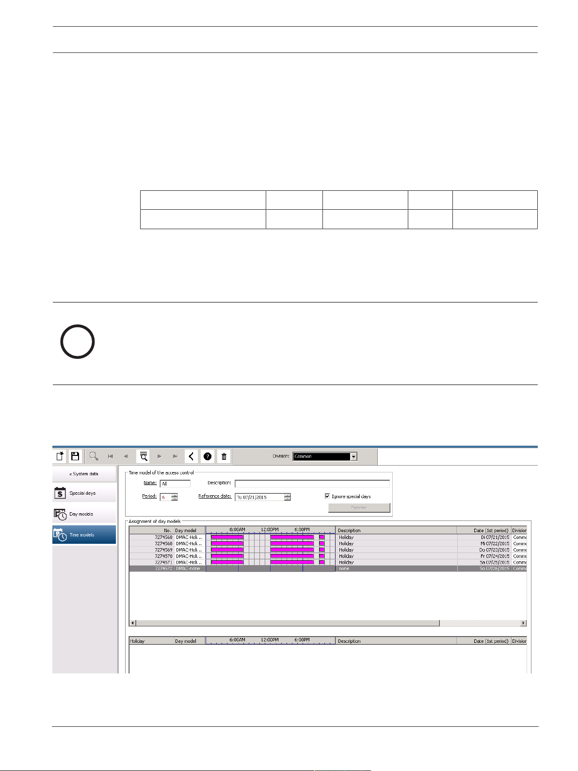
5.3 Defining Time models
Existing time models can be selected from the search list and their details displayed in the
dialog fields. Any processing is carried out in line with the procedure for creating new time
models.
Bosch Security Systems
Software manual
2021-03 | 3.0.1.1 |
Page 16
16 en | Configuring the calendar Access Management System
If the mask is empty, time models can be created from scratch. To do this, you must enter a
name and the number of days in the period and select a starting or reference date. When this
data is confirmed (Enter), a list appears in the Assignment of day models dialog field below
it. The number of lines in this list corresponds to the number of days set above, and the
columns already contain a progressive number and the dates for the period, beginning with
the start date selected.
Only entries of the column "Name" can be changed or inserted by the user in this list - as
already mentioned, the entries in the columns “No” and “Date” arise from the declarations of
the dialog head; the column "Description" is filled out by the system with the choice of a day
model and the explanations done in this dialog.
By double-clicking in the relevant line of the Day model column, a selection list field is
activated. One of the existing day models can be selected from this list. In this way, a specific
day model can be assigned to each day of the period. When the user switches to another line,
an existing description of the selected day model is indicated by the system in the Description
column.
The predefined holidays with the relevant day models are shown in the lower list field for
navigation and checking purposes. For the selected or newly created time model, the
assignment of day models to certain holidays can be changed. However, these changes will
only apply to this particular time model - general changeovers that are to apply to all existing
and future models can only be performed in the Holidays dialog. In line with these settings,
the week days are then given the assigned day models, in consideration of the holidays.
Then appropriately to these settings the weekdays are faced with the assigned day models
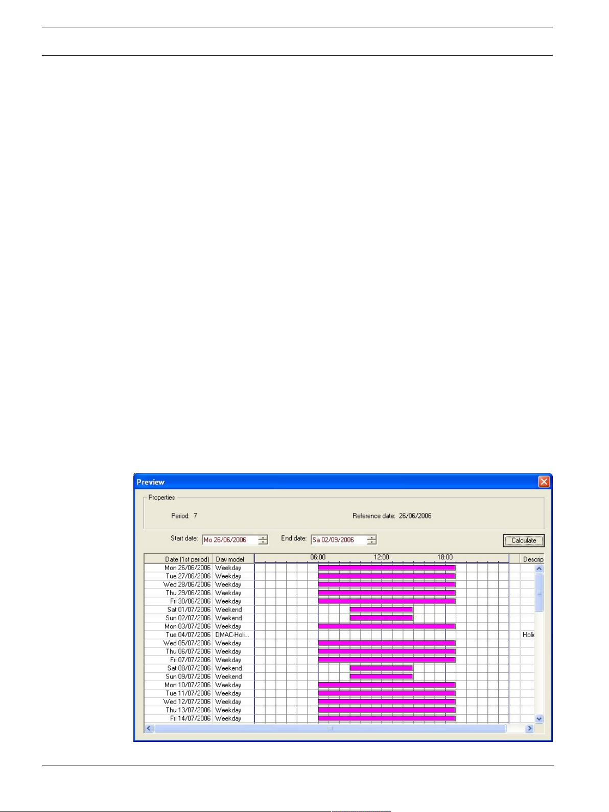
under consideration of the special days. To quickly check that day models are have been used
and assigned correctly - particularly on holidays - this dialogue contains a preview that shows
the day allocation of certain periods.
Finally, a separate dialog box is opened by clicking the Preview button and a time period of up
to 90 days can be specified, including holidays. When the Calculate button is clicked, the
report is composed and displayed as shown below - this process can take a few seconds
depending on the size of the interval.
2021-03 | 3.0.1.1 |
Software manual
Bosch Security Systems
Page 17
Access Management System Configuring the calendar | en 17
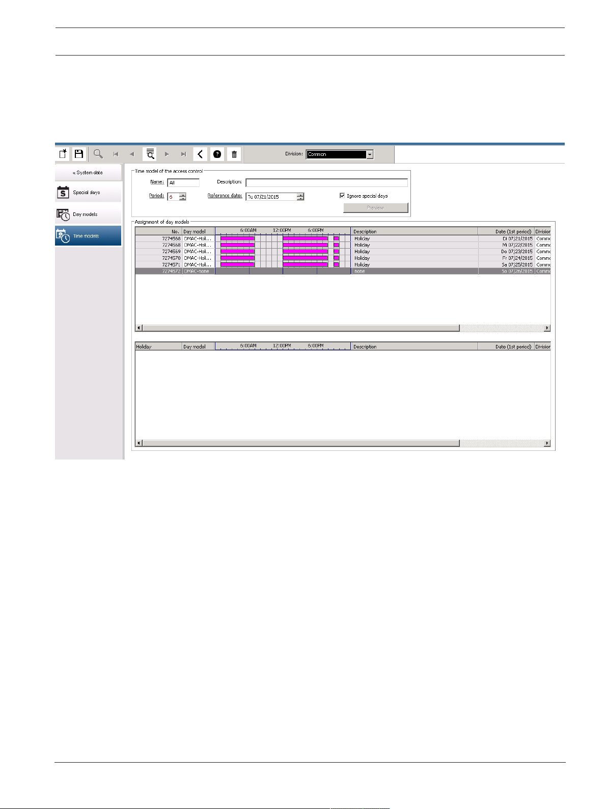
In the default setting the special days are applied to the time models according to their
definitions. Should the special days find, however, exceptionally no consideration, this can be
caused by the choice of the option Ignore special days. Simultaneously the entries from the
two lower lists are deleted, so that it is evident to the user immediately that the special days
and day classes find no use in this model.
Bosch Security Systems
Software manual
2021-03 | 3.0.1.1 |
Page 18
18 en | Configuring Divisions Access Management System
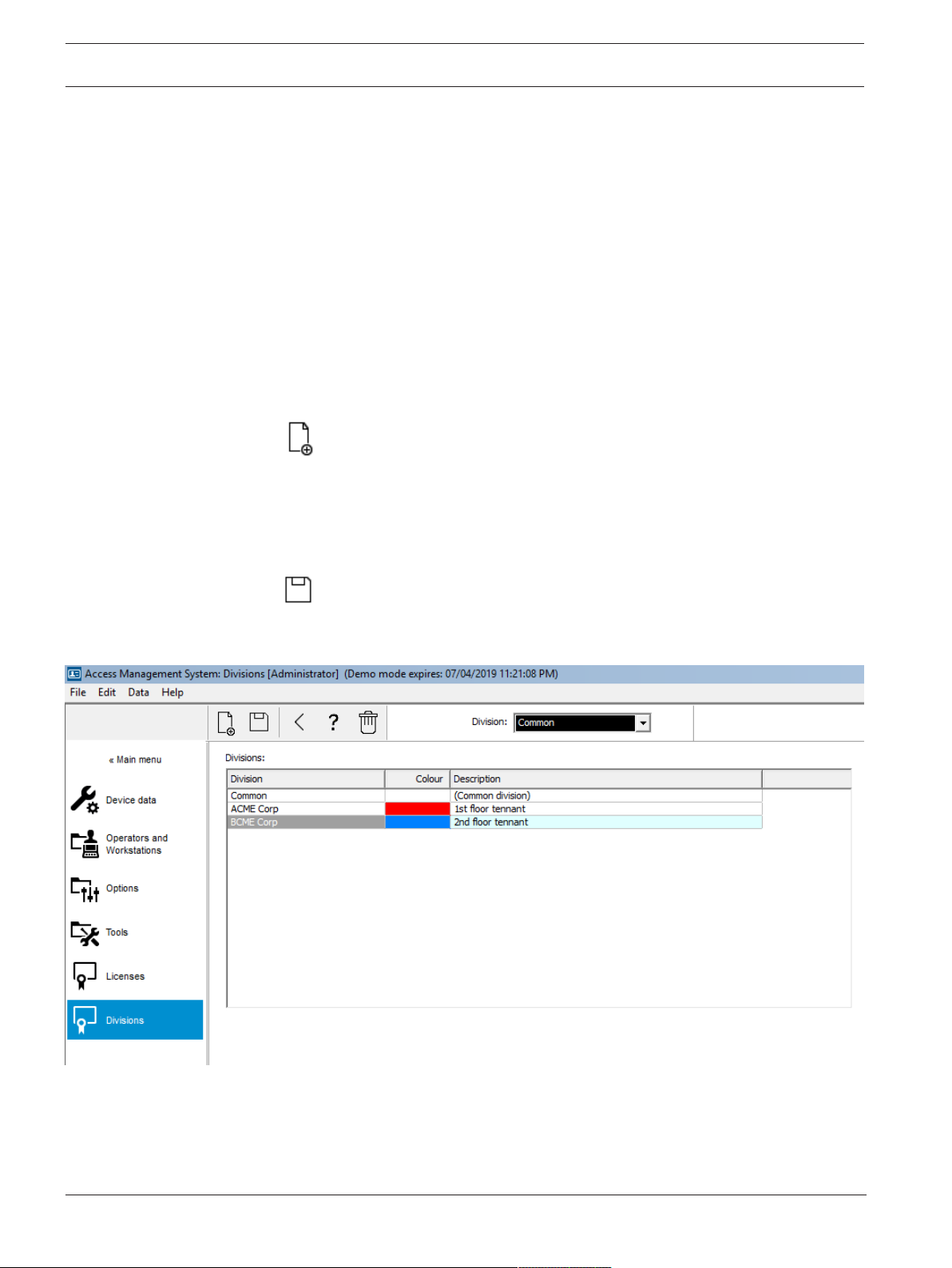
6 Configuring Divisions
Introduction
The system may be licensed optionally to provide joint access control for a facility which is
shared by any number of independent parties, called Divisions.
System operators can have one or more divisions assigned to them. Operators then see only
the persons, devices and entrances of those divisions.
Where the Divisions feature is not licensed, all objects managed by the system belong to a
single division called Common.
Prerequisites
– The Divisions feature is licensed for your installation.
Dialog path
– Main menu > Configuration > Divisions
Procedure
1. Click in the tool bar.
– A new Division is created with a default name.
2. Overwrite the default name and (optional) enter a description for the benefit of other
operators.
3. Click in the Color column to assign a color to help distinguish the division’s assets in the
user interface.
4. Click to save
6.1 Assigning Divisions to devices
Assign Divisions to devices in the Device editor
Dialog path
Main menu > Configuration > Device data
2021-03 | 3.0.1.1 |
Software manual
Bosch Security Systems
Page 19
Access Management System Configuring Divisions | en 19
i
Prerequisites
– Divisions are licensed and in operation
– At least one division has been created.
Procedure
1. In the Device tree, select the device for assignment.
– The device editor appears in the main dialog pane.
2. From the Division list, select the new division for the device
– The list box reflects the new division.
3. Click (Save) to save
Notice!
All components of an entrance must belong to one division
The system will not allow you to save an entrance until all its components belong to the same
division.
6.2 Assigning Divisions to operators
Assign Divisions to operators in the User rights dialog
Dialog path
Main menu > Configuration > Operators and workstations > User rights
Prerequisites
– Divisions are licensed and in operation
– At least one division has been created.
– At least one operator has been created in the system
Procedure
1. In the User rights dialog, select the personnel record of the operator to be assigned.
2. On the Divisions tab, use the arrow keys to move divisions from the list of Available
divisions to the list of Assigned divisions for this operator.
3. Click (Save) to save
Bosch Security Systems
Software manual
2021-03 | 3.0.1.1 |
Page 20

20 en | Configuring the IP addresses Access Management System
7 Configuring the IP addresses
The local access controllers on the network require a consistent scheme of IP addresses in
order to participate in the access control system. The AccessIPConfig tool locates the
controllers on the network and provides a convenient interface to administer their addresses
and other network options centrally.
Prerequisites
– The local access controllers are powered on and connected to the network.
– You have a scheme for the IP addresses of the controllers, and their passwords if
required.
Dialog path
Main menu > Configuration > Tools
Procedure
1. Follow the dialog path above and click Configuration AMC and fingerprint devices
The AccessIPConfig tool opens.
2. Click Scan AMCs
The local access controllers that are available on the network are listed, each with the
following parameters:
– MAC address: The hardware address of the controller. Note, this is not the address
of its Main Access Controller , which is called MAC only by coincidence.
– Stored IP address:
– Port number: The default is 10001
– DHCP: The value is Yes only if the controller is configured to receive an IP address
from DHCP
– Current IP addresss
– Serial number
– Notes added by the network configuration team
3. Double-click an AMC in the list to change its parameters in a popup window. Alternatively,
select the line of the desired AMC and click Set IP… Note that it may be necessary to
enter a password, if one has been configured for the device.
The modified parameters are stored as soon as you click OK in the popup window.
4. When you have finished configuring the IP parameters of the controllers, click File > Exit
to close the tool.
You will return to the main application.
2021-03 | 3.0.1.1 |
For more detailed information, click Help in the AccessIPConfig tool to view its own help file.
Software manual
Bosch Security Systems
Page 21
Access Management System Using the Device Editor | en 21
8 Using the Device Editor
Introduction
The Device Editor is a tool for adding, deleting or modifying entrances and devices.
The Device Editor offers views for the following editable hierarchies:
– Device configuration: the electronic devices within the access control system.
– Workstations: the computers cooperating in the access control system.
– Areas: the physical areas into which the access control system is divided.
Prerequisites
The system is correctly installed, licensed and on the network.
Dialog path
– Main menu >Configuration > Device data
Using the Device Editor toolbar
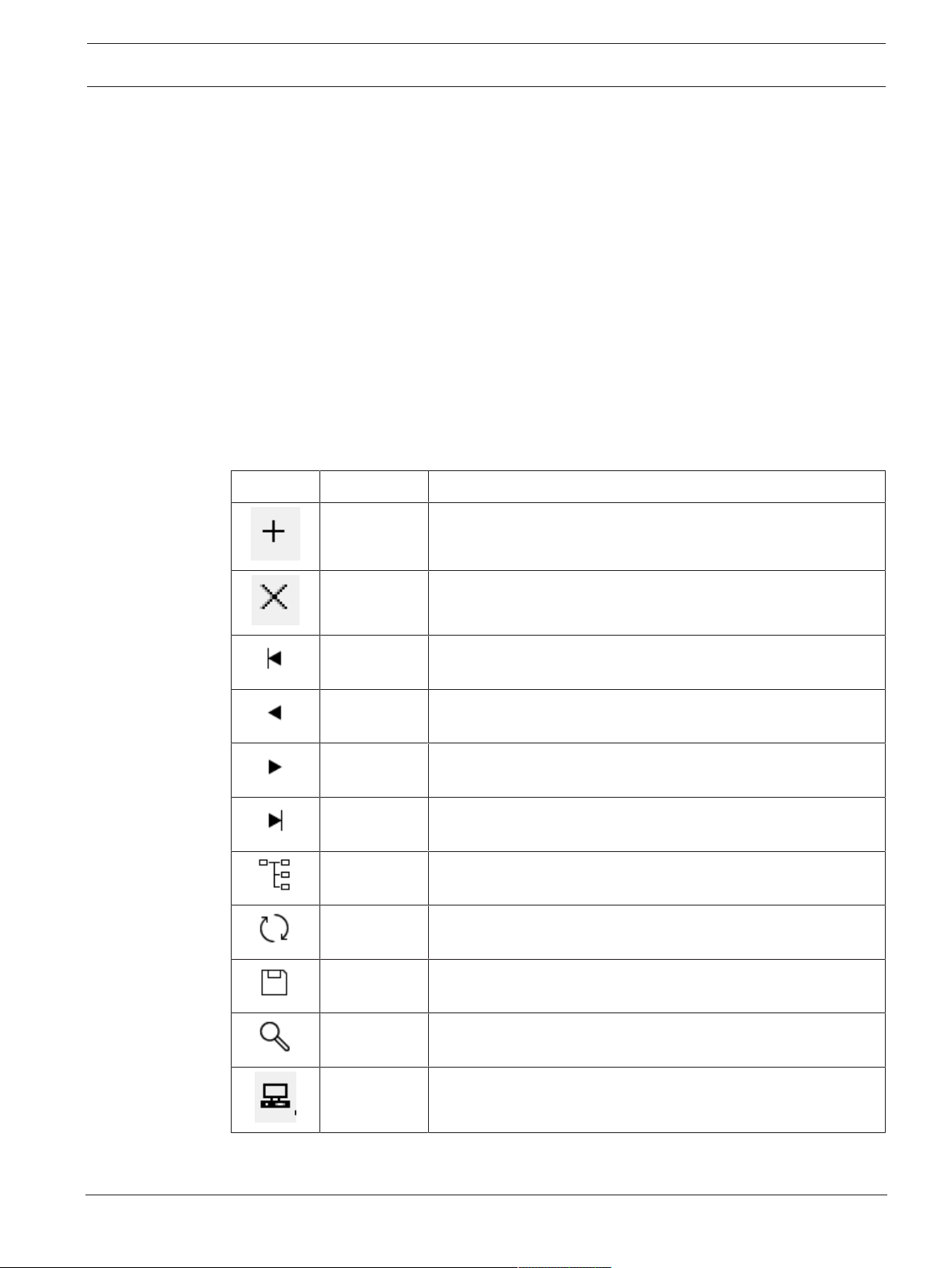
The Device Editor toolbar offers the following functions, regardless of which view is active:
Devices, Workstations or Areas.
Button Shortcut Description
Ctrl + N Creates a new item below the selected node.
Alternatively, right-click the node to invoke its context menu.
Del Deletes the selected item and all beneath it.
Ctrl-Page up First item in the tree
Ctrl - Previous item
Ctrl + Next item
Ctrl-Page
Last item in the tree
down
Ctrl-A Expands and collapses the tree.
Ctrl-K Refreshes the data by reloading them from the database.
All unsaved changes are discarded.
Ctrl-S Saves the current configuration
Ctrl-F Opens a search window
Bosch Security Systems
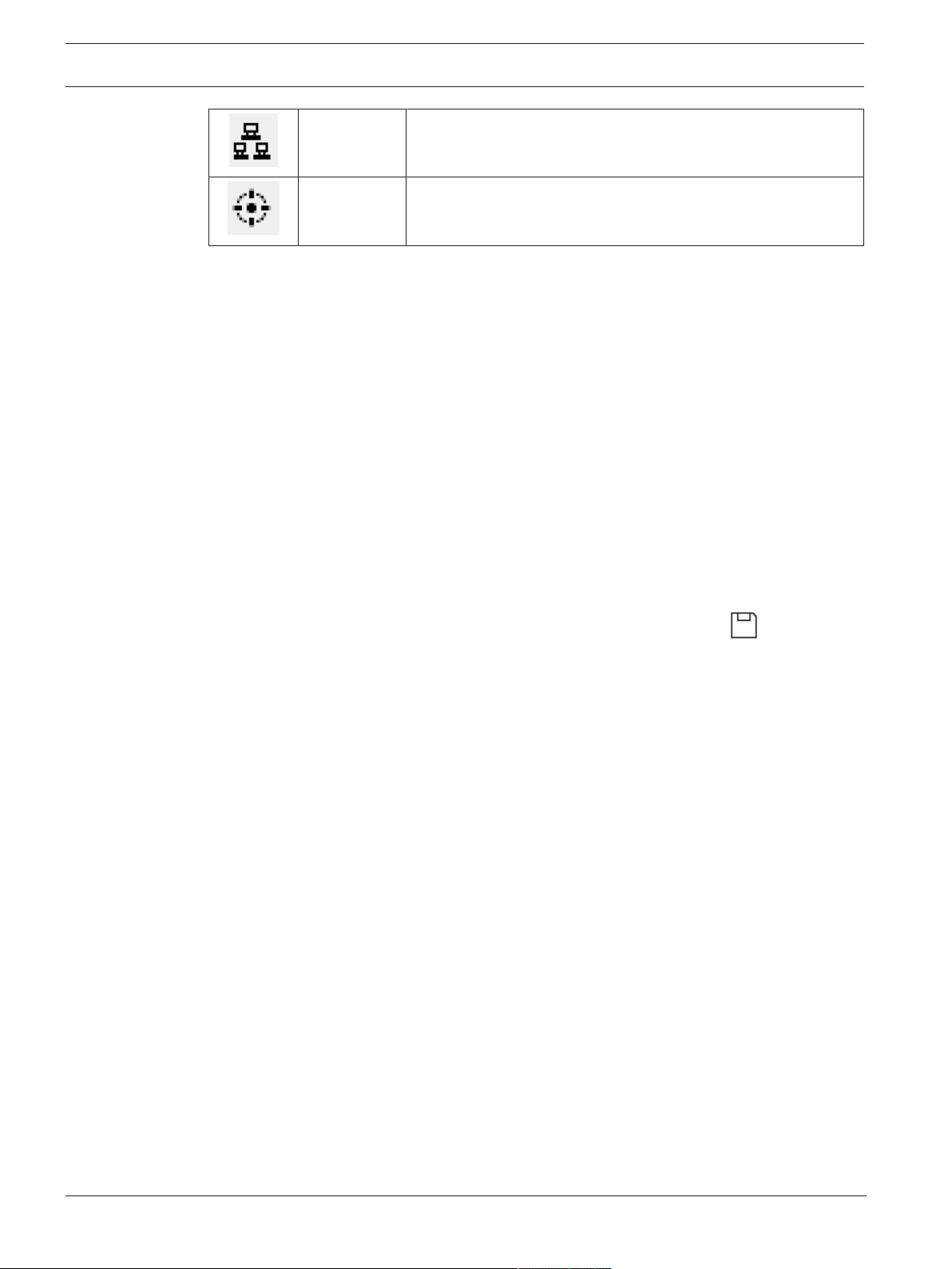
Open the Device configuration tree
Software manual
2021-03 | 3.0.1.1 |
Page 22
22 en | Using the Device Editor Access Management System
Open the Workstations tree
Open the Areas tree
In all Device Editor views, start at the root of the tree and add items using the toolbar buttons,
the menu or the context menu of each item (right-click to invoke it). To add sub-items to a
device, first select the parent device under which the sub-items should appear.
Copying and pasting AMC devices
To copy AMC devices from one part of the tree to another:
1. Right-click the AMC device and select Copy from the context menu.
2. Right-click on a suitable parent device elsewhere in the tree, and select Paste from the
context menu.
– The device is copied to the new location with its sub-devices and settings.
– Device parameters such as IP address and Name, which must be unique, are not
copied.
3. Enter unique values for those device parameters that require them. Until you do this you
cannot save the device tree.
Saving your work
When you have finished adding and modifying items in the tree, click Save to save the
configuration.
To close the Device Editor, click File > Exit.
2021-03 | 3.0.1.1 |
Software manual
Bosch Security Systems
Page 23
Access Management System Configuring areas of access control | en 23
i
9 Configuring areas of access control
Introduction to Areas
Secured facilities can be divided into Areas. Areas can be of any size: one or several buildings,
single floors or even single rooms.
Some uses of Areas are:
– The localization of individual persons within the secured facilities.
– The estimation of the number of persons within a given area, in case of an evacuation or
other emergency.
– Limiting the number of persons or vehicles in an area:
When the predefined population limit is reached, further admissions can be rejected until
persons or vehicles leave the area.
– Implementing access sequence control and anti-passback
The system distinguishes between two types of access-controlled areas
– Areas for persons
– Areas for vehicles (parking lots)
Each area may have sub-areas for finer granularity of control. Areas for persons may have up to
3 levels of nesting, and areas for parking lots only 2, namely the overall parking lot and parking
zones, between 1 and 24 in number.
The default area, which exists in all installations, is called Outside. It serves as the parent for
all user-defined areas of both kinds: person and parking lots.
An area is not usable unless at least one entrance leads into it.
Device Editor DevEdit can be used to assign a location area and a destination area to any
entrance. When someone scans a card at a reader belonging to an entrance, the person’s new
location becomes the destination area of that entrance.
Notice!
Access sequence control and anti-passback require both entrance and exit readers at the
areas' entrances.
Turnstile-type entrances are strongly recommended to prevent accidental or deliberate
“tailgating "
Procedure for creating areas
Prerequisites
As a system operator you require an authorization from your system administrator to create
areas.
Dialog path (AMS)
1. In the AMS dialog manager select Main menu > Configuration > Device data
2. Click Areas
Bosch Security Systems
3. Select the node Outside, or one of its children, and click in the toolbar.
Alternatively, right-click Outside to add an area via its context menu.
All areas created initially receive a unique name of Area plus a numeric suffix.
Software manual
2021-03 | 3.0.1.1 |
Page 24
24 en | Configuring areas of access control Access Management System
4. In the popup window select its type, that is Area for persons or Parking lot for vehicles.
Note that only Outside can have children of both types. Any sub-area of these children
always inherits the type of its parent.
– Areas for persons can be nested to three levels. For each area or sub area you can
define a maximum population.
– Parking lots are virtual entities consisting of at least one parking zone. If the
population of a parking lot does not need to be limited by the system, 0 is displayed.
Otherwise the maximum number of parking spaces per zone is 9999, and the parking
lot main pane displays the sum of all the spaces in its zones.
Procedure for editing areas
1. Click an Area in the hierarchy to select it.
2. Overwrite one or more of the following attributes in the main pane of the dialog.
Name The default name, which you may overwrite.
Description A free-text description of the area.
Maximum number of
persons / cars
Default value 0 (zero) for no-limit.
Else, enter an integer for its maximum population.
Notes:
– An area cannot be moved by dragging and dropping to a different branch of the hierarchy.
If necessary, delete the area and recreate it on another branch.
Procedure for deleting areas.
1. Click an area in the hierarchy to select it.
2. Click Delete or right-click to delete via the context menu.
Note: an area cannot be deleted until all its children have been deleted.
9.1 Configuring areas for vehicles
Creating areas for vehicles (parking lot, parking zone)
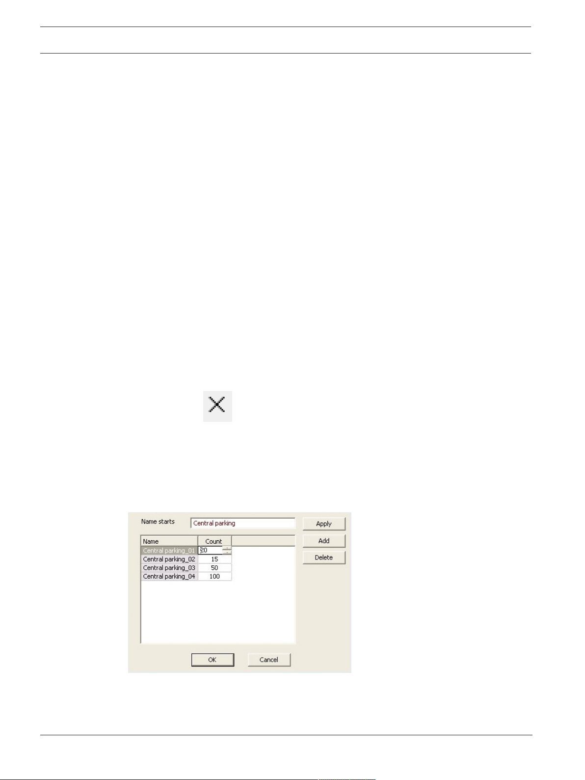
If you select an area type of Parking lot a popup window appears.
2021-03 | 3.0.1.1 |
1. Enter a name in the field Name starts with to create a trunk name for all its parking subareas or parking zones.
Up to 24 parking zones can be created using the Add button, and each will have the
trunk name plus a 2-digit suffix.
Software manual
Bosch Security Systems
Page 25

Access Management System Configuring areas of access control | en 25
2. If the system is to limit the population of these areas, enter the number of parking spaces
in the Count column. If no population limit is required, enter 0.
Note: The maximum population of the entire parking lot is the sum of these numbers. Only
parking zones can contain parking spaces; the parking lot is only a virtual entity consisting of
at least one parking zone. The maximum number of parking spaces per zone is 9999.
Creating entrances for parking lots
As with normal areas, parking lots require an entrance. The appropriate door model is
Parkinglot05c.
For monitoring the population of a parking lot 2 entrances with this door model are required
on the same AMC, one for ingress and one for egress.
Prerequisite
Create a parking lot with at least one parking zone, as described above.
Dialog path
Main menu > Configuration > Device data
Click LACs/Entrances/Devices
Procedure
1. In the device hierarchy, create an AMC, or select an AMC that has no dependent
entrances.
2. Right-click the AMC and select New entrance
3. In the New entrance popup window select Entrance model Parkinglot05c and add an
inbound reader of the type installed at the parking lot entrance.
4. Click OK to close the popup window.
5. Select this newly created entrance in the device hierarchy.
– Note that the system has automatically designated the reader as an Entry reader.
6. In the main editing pane, on tab Parkinglot05c, select from the Destination pull-down
menu the parking lot that you created previously.
7. Right-click the AMC again, and create another entrance of type Parkinglot05c as above.
– Note that this time you can only select an outbound reader.
– Click OK to close the popup window.
8. Select this second newly created entrance in the device hierarchy
– Note that the system has automatically designated the second reader as an Exit
reader.
Bosch Security Systems
Software manual
2021-03 | 3.0.1.1 |
Page 26

26 en | Configuring intrusion areas and panels Access Management System
10 Configuring intrusion areas and panels
Introduction
The access control system supports the administration and operation of Bosch intrusion
panels. Consult the datasheet of the access control system for details of the models that it
supports. The access control system adds particular value in the administration of the
intrusion panel users. These users are a subset of the cardholders of the overall access
control system. Access control system administrators give these cardholders special
authorizations to administer and operate the intrusion panels through the AMS Dialog
Manager.
The intrusion panels themselves are configured and updated as previously through their
RemoteProgrammingSoftware (RPS). AMS continually reads from the RPS database, and
displays the panels that are in it.
AMS contains dialogs to create panel users and their authorization profiles, and to manage the
panels.
Prerequisites
– The RPS of supported Bosch intrusion panels is installed on a separate computer in the
AMS system, not on the AMS server. Consult the RPS installation guide for installation
instructions.
– RPS has been configured with the intrusion panels that will belong to the AMS access
control system. Consult the RPS user guide or online help for instructions.
– The clocks on the panels are within 100 days of the clock on the AMS server, to enable
automatic synchronization.
– Mode 2 protocol is set on all participating panels.
– Cards with one of the following standard card definitions:
– HID 37 BIT -> Intrusion 37 BIT with a facility/site code of 32767 or lower.
– HID 26 BIT- > Intrusion 26 BIT
– EM 26 BIT- > Intrusion 26 BIT
Overview
The configuration process consists of the following stages, described in the following sections
in this chapter:
1. Connecting the access control system to the intrusion panels.
– Connecting to the RPS API.
– Configuring the panel connections.
2. Creating panel authorization profiles that govern which functions of the connected panels
can be used.
3. Assigning panel authorization profiles to cardholders.
– These cardholders thus become operators for the intrusion panels.
10.1 Connecting the access control system to the intrusion panels
Introduction
This section describes how to view the intrusion panels and make them available for control
through Map View. The access control system connects to one RPS on its network, and
through it maintains an up-to-date internal list of the compatible intrusion panels that are
available.
Dialog path
Main menu > Configuration > Panels and subdialogs
2021-03 | 3.0.1.1 |
Software manual
Bosch Security Systems
Page 27
Access Management System Configuring intrusion areas and panels | en 27
10.1.1 Step 1: Connecting to the RPS API
The RPS API is an interface to the RPS, which is running on a separate computer. Step 1 is to
provide the computer's address and administrator login information to the access control
system.
Dialog path
Main menu > Configuration > Panels > RPS API configuration
Procedure
1. Enter the following information:
Information Description
Host name / IP address The HTTPS address of the computer on which the RPS is
running, and the port number through which the RPS
communicates.
The default port number is 9000.
User name The user name of an RPS administrator user for the API.
Password The password of the RPS administrator user.
2. Click the button Test the connection to ensure that the RPS is running, and that the user
name and password are valid
10.1.2 Step 2: Configuring the panel connections
Step 2 is to define the amount of control that the access control system has over individual
panels on the network.
Dialog path
Main menu > Configuration > Panels > Panel administration
The dialog maintains a list of the compatible intrusion panels that the RPS API has provided to
the AMS.
The list is periodically updated in the background. After you open the dialog, click
occasionally, to force an immediate update manually.
The list is read-only, except for the controls described in the following section.
Procedure
Use the controls below to allow control of individual intrusion panels by the access control
system.
List column
Useradministration
Select the check box to ensure that the users of the intrusion
panel in this row are maintained in the access control system and
not on the panel itself.
IMPORTANT: this setting causes all panel users that were created
locally in RPS to be overwritten.
Bosch Security Systems
List column MapView Select the check box to make this panel available for Command
and Control through the Map View .
Software manual
2021-03 | 3.0.1.1 |
Page 28
28 en | Configuring intrusion areas and panels Access Management System
If you selected the check box in the Map View column, click the
icon to enter a host name or IP address, a port and the passcode
Settings (cog)
for the individual panel.
icon in the Access data
column.
Button:
Deleteselectedpanel
If a panel has been deleted in RPS it appears with a status of
Removed in the list. Select the panel and click this button to
delete it completely from the database.
10.2 Creating authorization profiles for panels
Introduction
This section describes how to create panel authorization profiles.
A panel authorization profile is a custom set of authorizations to operate a custom set of
intrusion panels. An AMSadministrator can create multiple panel authorization profiles for the
various responsibilities of various groups of cardholders.
Dialog path
Main menu > System data > Authorization profiles for intrusion panels
Procedure
1. Click to create a new profile
2. (Mandatory) Enter a name for the profile
3. (Optional) Enter a free-text description for the panel
4. Below the Assigned panels list, click Add… to add one or more panels from a popup list
of panels available on the network.
Conversely, select one or more panels and click Remove to remove them from the list.
5. Click a panel in the Assigned panels list to select it.
– In the Authorizations pane, a list appears containing all the intrusion areas that
belong to the selected panel.
6. In the Authorizations list, in the column Authority level, select an authority level for each
intrusion area of the panel that is to be included in this profile.
– The authority levels are defined and maintained in RPS. They may be customized
there also. Make sure you know the definition of the authority level in RPS before
assigning it to a profile.
– By default L1 is the highest authority level, with L2, L3 etc. increasingly restricted.
– If you leave a cell blank, then the recipient of this profile will have no authorization
over the selected intrusion area of the selected panel.
7. Repeat this process for all the intrusion areas of all the panels to be included in this
profile.
8. (Optional) From the User group list, select a panel user group in order to restrict the
authorizations to certain time periods.
– The user groups are defined and maintained in RPS. They may be customized there
also. Make sure you know the definition of the user group in RPS before assigning
the user group to a profile.
2021-03 | 3.0.1.1 |
9. Click (Save) to save the changes.
Software manual
Bosch Security Systems
Page 29

Access Management System Configuring intrusion areas and panels | en 29
10.3 Assigning panel authorization profiles to cardholders
Introduction
This section describes how to assign different panel authorization profiles to different types or
groups of cardholders.
Prerequisite
You have defined one or more panel authorization profiles in the access control system.
Dialog path
Main menu > Persons > Cards
Procedure
1. In the usual way, find and select the desired cardholder from the database.
2. Click the Intrusion tab.
3. On the Intrusion tab, select the check box Panel user.
4. (Mandatory) In the Passcode field, type a passcode through which this cardholder will
operate the intrusion panels.
– If required, use the button to generate an unused new passcode.
5. In the ID card list, select one of the access control credentials that is assigned to this
cardholder.
6. (Optional) In the Number of remote field, enter the number that is printed on the
cardholder's remote control device for intrusion panels.
7. In the Language list, select the language in which the cardholder prefers to read panel
dialogs.
8. If the cardholder is to use the Bosch smartphone application for intrusion panels, select
the Remote access check box.
9. From the Authorization profile list, select a suitable panel authorization profile for the
cardholder.
10. Click (Save) to save the changes.
– This panel authorization profile, with all its panels and authorizations, is assigned to
the cardholder. The cardholder thus becomes an operator for the intrusion panels.
Note that you can also use the data fields on this dialog with the button to find
cardholders in the database.
Bosch Security Systems
Software manual
2021-03 | 3.0.1.1 |
Page 30

30 en | Configuring operators and workstations Access Management System
11 Configuring operators and workstations
Introduction to access-control administration rights
Administration rights for the access control system determine which system dialogs may be
opened, and which functions may be performed there.
Rights can be assigned to both operators and workstations.
The rights of a workstation may temporarily restrict the rights of its operator, because
security-critical operations should only be performed from workstations that are especially
secure.
Rights are assigned to operators and workstations in bundles called Profiles. Each profile is
tailored to the duties of one of a particular type of operator or workstation.
Each operator or workstation may have multiple authorization profiles.
Overall procedure and dialog paths
1. Create the workstations in the Device Editor:
Configuration > Device data > Workstations
2. Create workstation profiles in the dialog:
Operators and workstations > Workstation profiles.
3. Assign profiles to workstations in the dialog:
Operators and workstations > Workstation rights
4. Create operator profiles in the dialog:
Operators and workstations > User profiles dialog.
5. Assign profiles to operators in the dialog:
Operators and workstations > User rights dialog
11.1 Creating the workstations
Workstations are the computers from which operators operate the access control system.
First a workstation must be “created”, that is, the computer is registered within the access
control system.
Dialog path
Configuration > Device data > Workstations
Procedure
1. Right-click DMS and select New object from the context menu, or click on the toolbar.
2. Enter values for the parameters:
– The Name of the workstation must match the computer name exactly
– Description is optional. It can be used, for example, to describe the function and the
location of the workstation
– Login via reader Leave this check box clear unless operators are to log on to this
workstation by presenting cards to an enrollment reader connected to this
workstation. For details see the section 2-Factor Authentication
– Automatic logout after: The number of seconds after a logon via enrollment reader
is automatically terminated. Leave at 0 for unlimited time.
2021-03 | 3.0.1.1 |
Software manual
Bosch Security Systems
Page 31

Access Management System Configuring operators and workstations | en 31
i
11.2 Creating workstation profiles
Introduction to workstation profiles
Depending on its physical location, an access control workstation should be carefully
configured regarding its usage, for example:
– Which operators may use it
– What credentials are necessary to use it
– What access control tasks may be performed from it
A workstation profile is a collection of rights that defines the following:
– The menus of the dialog manager and the dialogs which can be used at a workstation
– Which user profile(s) an operator must have to in order to log in at this workstation.
Notice!
Workstation profiles override user profiles
An operator can employ only those of his user profile rights which are also included in the
workstation profile of the computer where he is logged on. If the workstation and operator
profiles have no rights in common, the user will lack all rights at that workstation.
Dialog path
Configuration > Operators and workstations > Workstation profiles
Creating a workstation profile
1. Click to create a new profile
2. Enter a profile name in the Profile Name field (mandatory)
3. Enter a profile description in the Description field (optional but recommended)
4. Click or Apply to save your changes
Assigning execution rights for system functions
1. In the Functions list, select the functions that are to be accessible to this workstation
and double-click them to set the value in the Execute column to Yes.
– Likewise ensure that all the functions that are not to be accessible are set to No.
2. Click or Apply to save your changes
Assigning User profiles to Workstation profiles
In the User Profile pane.
The Assigned Profiles list contains all user profiles authorized to log onto a workstation with
this workstation profile.
The Available Profiles field contains all other profiles. These are not yet authorized to log onto
a workstation with this workstation profile.
Bosch Security Systems
1. Click the arrow buttons between the lists to transfer selected profiles from one list to the
other.
2. Click or Apply to save your changes
Software manual
2021-03 | 3.0.1.1 |
Page 32

32 en | Configuring operators and workstations Access Management System
i
i
Notice!
The default administrator profiles for the user (UP-Administrator) and the workstation (WPAdministrator) cannot be changed or deleted.
The profile WP-Administrator is irrevocably bound to the server workstation. This guarantees
that there is at least one user who can log onto the server workstation.
11.3 Assigning workstation profiles
Use this dialog to manage the assignments of Workstation profiles to Workstations. Every
workstation must have at least one workstation profile. If it has multiple profiles then all rights
in those profiles apply simultaneously.
Dialog path
Configuration > Operators and workstations > Workstation rights
Procedure
The Assigned Profiles list contains all the workstation profiles that already belong to this
workstation.
The Available Profiles list contains all workstation profiles that have not yet been assigned to
this workstation.
1. In the list of workstations, select the workstation you wish to configure
2. Click the arrow buttons between the Assígned and Available lists to transfer selected
profiles from one to the other.
3. Click or Apply to save your changes
Notice!
The default administrator profiles for the user (UP-Administrator) and the workstation (WPAdministrator) cannot be changed or deleted.
The profile WP-Administrator is irrevocably bound to the server workstation. This guarantees
that there is at least one user who can log onto the server workstation.
11.4 Creating user (operator) profiles
Introduction to user profiles
Note: The term User is synonymous with Operator in the context of User rights.
A user profile is a collection of rights that defines the following:
– The menus of the dialog manager and the dialogs which are visible to the operator.
– The capabilities of the operator in those dialogs, basically the rights to execute, change,
add and delete the elements of those dialogs.
User profiles should be carefully configured, depending on the person’s experience, security
clearance and responsibilities:
2021-03 | 3.0.1.1 |
Dialog path
Configuration > Operators and workstations > User profiles
Procedure
1. Click to create a new profile
2. Enter a profile name in the Profile Name field (mandatory)
Software manual
Bosch Security Systems
Page 33

Access Management System Configuring operators and workstations | en 33
i
3. Enter a profile description in the Description field (optional but recommended)
4. Click or Apply to save your changes
Notice!
Choose profile names that clearly and accurately describe the profile’s capabilities and
limitations.
Adding editing and execution rights for system functions
1. In the list pane, select the functions (first column) and the capabilities within that
function (Execute, Change, Add, Delete) that are to be accessible to this profile. Doubleclick them to toggle their settings to Yes.
– Likewise ensure that all the functions that are not to be accessible are set to No.
2. Click or Apply to save your changes
11.5 Assigning user (operator) profiles
Note: The term User is synonymous with Operator in the context of User rights.
Prerequisites
– The operator who is to receive this user profile has been defined as a Person in the
access control system.
– A suitable user profile has been defined in the access control system.
– Note that it is always possible to assign the unrestricted user profile UP-
Administrator, but this practice is deprecated for security reasons.
Dialog path
Configuration > Operators and workstations > User rights
Procedure
1. Load the personnel record of the intended user into the dialog.
2. If required, limit the validity of the user profile by entering dates in the fields Validfrom
and Validuntil.
Assigning User profiles to operators
In the User Profiles pane:
The Assigned Profiles list contains all user profiles that have been assigned to this user.
The Available Profiles field contains all profiles that are available for assignment.
1. Click the arrow buttons between the lists to transfer selected profiles from one list to the
other.
2. Select the Global administrator check box to give this operator read+write access to
those personnel records where the administered globally attribute is activated. The
default operator access to such personnel records is read only.
Bosch Security Systems
3. Click to save your changes.
Assigning API usage rights to operators
Software manual
2021-03 | 3.0.1.1 |
Page 34

34 en | Configuring operators and workstations Access Management System
If configured and licensed, external program code can invoke features of the access control
system via an Application Programming Interface or API. The external program acts through a
proxy operator within the system. The API usage drop-down list controls the capabilities of
the current operator if it is used as a proxy operator by external code.
Configuration > Operators and workstations > User rights
– Select a setting from the API usage list.
The choices are:
No access The operator can not be used by the API to perform system functions.
Read only The operator can be used by the API to read system data, but not to add,
modify or delete it.
Unlimited The operator can be used by the API to read, add, modify and delete system
data.
– Click to save your changes
11.6 Setting passwords for operators
How to set secure passwords for oneself and others.
Introduction
The system requires at least one operator. The default operator in a new installation has
username Administrator and password Administrator. The first step in configuring the system
should always be to log on with those credentials and change the password for Administrator,
in accordance with your organization’s password policies.
After that you can add other operators, both privileged and unprivileged.
Procedure for changing one’s own password.
Prerequisites
You are logged onto the dialog manager.
Procedure
1. In the dialog manager, select menu: File > Change password
2. In the popup window, enter the current password, the new password, and the new
password again to confirm.
3. Click Change.
Note that this procedure is the only way to change the Administrator password.
Upon first logon after an installation, the system requires that you change the Administrator
password.
Procedure for changing the passwords of other operators.
Prerequisites
To change the passwords of other users you must be logged onto the dialog manager using an
account with Administrator privileges.
Procedure
1. In the main menu of the dialog manager, navigate to Configuration > Operators and
Workstations > User rights
2. In the main dialog pane, use the tool bar to load the operator whose password you wish
to change.
3. Click Change password…
2021-03 | 3.0.1.1 |
Software manual
Bosch Security Systems
Page 35

Access Management System Configuring operators and workstations | en 35
4. In the popup window, enter the new password and the new password again to confirm.
5. In the popup window, enter the period of validity for the new password, either Unlimited
or a number of days.
– For production environments it is urgently recommended that you set a validity
period.
6. Click OK to close the popup window.
In the main dialog window, click the icon to save the user record.
Note that the date pickers Valid from and Valid until, below the Change password… button,
refer to the validity of the user rights in this dialog, not to the password.
Further information
Always set passwords according to the password policy of your organization. For guidance on
creating such a policy you may consult, for example, the guidance provided by Microsoft at the
following location.
https://www.microsoft.com/en-us/research/publication/password-guidance/
Bosch Security Systems
Software manual
2021-03 | 3.0.1.1 |
Page 36

36 en | Configuring cards Access Management System
i
i
12 Configuring cards
12.1 Card Definition
Use this dialog to activate, deactivate, modify or add the card definitions to be used by your
access control system.
Dialog path
– AMS main menu > Configuration > Options > Card definition
The following types are predefined by the system, and are not modifiable:
– 32 Bit CSN - Standard MIFARE (32 bit)
– HID 26 - Standard Wiegand 26 bit code = active (default)
– HID 35 - HID corporate 1000
– HID 37 - HID 37 bit code - CN-H10304
– EM 26 - EM 26 Bit code
– Serial readers (AMC 4R4/LACi) - 64 bit
– HID 48 - HID corporate 1000
– 56 Bit CSN - Standard MIFARE Desfire
HID 26 is the default card type, and appears in the list Active card types
12.1.1 Creating and Modifying
Click the (green +) button above the right-hand list box to create a new list entry. In
contrast to predefined card types the data of newly created types are freely editable. Doubleclick the fields Name, Description and Number of Bits to edit them.
The name can have a maximum of 80 characters, and the description 255. The number of bits
is limited to 64 (if a higher number is entered then this will be reset to the maximum as soon
as the text field loses input-focus).
Notice!
Bit lengths are used to differentiate between Wiegand definitions. Therefore each new
definition must have a unique bit length which has not been used by an existing definition.
4 To modify a data bit, double-click the relevant field. To delete it, first select the data bit
then click the (red x) button.
Notice!
Only card types that were created by the user can be modified or deleted.
2021-03 | 3.0.1.1 |
When a single card type is selected (in left or right-hand lists) then its encoding is displayed in
the lower part of the dialog. The display shows data bits in 5 rows, and as many columns as
the number of bits in the definition.
Software manual
Bosch Security Systems
Page 37

Access Management System Configuring cards | en 37
Each column of the Field row can be given a label that determines how that part of the code is
to be interpreted. The labels available are as follows:
F Facility: marks the code part for
facility affiliation
C Code no: code part containing
the individual card number
E1 Even 1: bit to balance the first
Even Parity Mask
E2 Even 2: bit to balance the
second Even Parity Mask
O1 Odd 1: bit to balance the first
The declaration
of these values
activates the
check box for the
corresponding
line.
Odd Parity Mask
O2 Odd 2: bit to balance the
second Odd Parity Mask
1 Fix bit values contained in the
0
code
In the case of the labels E1, E2, O1 and O2 it is enough to select the check-box on the
corresponding row. The box on the Field row will automatically be marked accordingly.
Explanation:
The signal sent by a reader when presented with a card is made up of a series of zeros and
ones. For each card type the length of this signal (i.e the number of bits) is exactly defined.
In addition to the actual user data, which are saved as code data, the signal also contains
control data in order to a) identify the signal as a card signal, and b) verify correct
transmission.
In general the fixed zeros and ones are useful for identifying the signal type.
The parity bits, which must yield either a zero (Even Parity) or a one (Odd Parity) as a
checksum over selected bits of the signal, are used to verify correct transmission. The
controllers can be configured so that they calculate one or two checksums for Even Parities
and one or two checksums for Odd Parities.
In the list control, those bits can be marked in the respective lines for the parity checksums
(Even1, Even2, Odd1 and Odd2) which should be included in the checksum. In the top line
(Field) for every checksum used a bit is defined to balance the checksum according to the
parity type. If a parity option is not used, the corresponding line simply remains empty.
12.1.2 Activating / Deactivating card definitions
Up to 8 card definitions can be active simultaneously. The definitions to be activated must be
moved to the left-hand list Active Card Types. This is done by (multi-)selecting one or more
definitions on the right-hand side, and clicking the left arrow ( < )button.
Bosch Security Systems
Software manual
2021-03 | 3.0.1.1 |
Page 38

38 en | Configuring cards Access Management System
i
No more than four definitions can be moved at once. Once four definitions are in place then
any surplus are discarded from the move. To add more definitions to Active Card Types it will
be necessary to delete one or more of those present by (multi-)selecting and moving them to
the right-hand side using the ( > )button, thus deactivating them.
Notice!
To use readers with L-Bus or BG900 protocols, activate the card type Serial Reader. This
makes the manual input dialog Dialog Bosch available to the dialog manager of the access
control system.
12.1.3 Creating card data in the dialog manager
Manual data input
Different input methods are used for Wiegand and Bosch cards.
For all Wiegand definitions (HID 26, HID 35, HID 37 and 32 Bit CSN) the dialog box
Dialog(Wiegand) allows you to enter Customer code and Card no. (card number).
For serial readers the dialog box Dialog(Bosch) contains additional fields for Version and
Country code.
Data input by enrollment reader
In addition to manual data input, any workstation can be equipped with a dialog reader for
collecting card data. Use a reader from the list in the following dialog:
– AMS main menu > Configuration > Options > Card reader
If the chosen reader is an input reader for Wiegand cards then all active Wiegand card types
will be listed along with the reader
– AMS main menu > Personnel data > Cards > Reader button > ▶ (right arrow)
One of these card types must be selected in order to ensure the correct saving of the card
encoding. That is, the reader itself cannot be selected directly but only indirectly via the
choice of Wiegand definition.
If the required card type does not appear in the pull-down list, you must activate it in the card
definition dialog.
– AMS main menu > Configuration > Options > Card definition
2021-03 | 3.0.1.1 |
HITAG, LEGIC and MIFARE enrollment readers can be selected from the list directly.
Software manual
Bosch Security Systems
Page 39

Access Management System Configuring cards | en 39
Card definition for Divisions (multi-party capability)
If you have licensed the Divisions feature for managing multiple parties (aka "Divisions") within
the access-controlled premises, it is possible to configure a code area on the card that allows
the operator to distinguish between the cards of various Divisions. Use the optional fields
(only selectable where Divisions feature has been licensed) to define the position of the start
bit and the length of the Division coding on the cards.
12.2 Configuring card codes
The coding of the access control cards ensures that all card data is unique.
Dialog path
Main Menu > Configuration > Options > Card coding configuration
Entering numbers in the dialog
Entering numbers in the dialog
For convenience, you can enter numbers in decimal or hexadecimal formats. Select the radio
buttons Hexadecimal or Decimal according to the format specified by the cards’
manufacturer.
The main dialog pane is divided into two groups, which are described in more detail below:
– Card default code data
– Check membership only values
Card default code data
Use these text entry fields to define values for the Version, Country code, and the Facility
code which are assigned to the card number when the card is enrolled in the system. If the
fields are not writeable, then they are not relevant to any of the active card definitions. For
Bosch code all fields are writeable.
If the card is enrolled manually at an operator workstation, then a dialog appears displaying
the default values which may be customized for each card.
Entering code data:
If the data are provided by the manufacturer as decimal values, select the Decimal radio
button and enter the values provided, for example:
Version: 2
Country code: 99
Facility code: 56720
Click Apply to store the data.
Bosch Security Systems
Software manual
2021-03 | 3.0.1.1 |
Page 40

40 en | Configuring cards Access Management System
i
i
Notes on inputting default code data:
The default data are stored in the registry of the operating system and each badge number is
added at encoding time. Registration takes the form of an 8 digit hexadecimal value with
leading zeros as necessary.
If the code numbers are transferred completely then the system may convert from decimal to
hex, pad to 8 places with leading zeros and save the appropriate system parameter.
– Example:
– Input: 56720
– Conversion: DD90
– Saved as: 0000DD90
If the code numbers are transferred separately (split form) then only in decimal form. They
are converted to a 10-digit decimal number which is constructed as follows:
– Version: 2 digits
– Country code: 2 digits
– Facility code: 6 digits
– If any of the 10 digits are still empty then they are padded with leading zeros
– Example: 0299056720
This 10-digit decimal value is converted and stored as an 8 digit hexadecimal value.
– Example:
– decimal: 0299056720
– hexadecimal: 11D33E50
Notice!
The system validates hex values, in the case of split code numbers, in order to prevent the
input of invalid country codes (above hex 63 or decimal 99) and invalid facility codes (above
hex F423F or decimal 999,999)
Notice!
If the card capture occurs via a connected dialog reader then the default values are assigned
automatically. It is not possible to override the defaults when capturing from a reader.
In order to do so the capture type should be switched to Dialog
Manual entry of the card number is in decimal format.
When saving the data a 10-digit decimal value (with leading zeros) is created, which is then
converted to an 8 digit hexadecimal value. This value is now stored with the default code data
as the 16-digit code number of the card.
– Example:
– Input of the card number: 415
– 10-digit: 0000000415
– Converted to hexadecimal: 0000019F
– Combined with the default Code data (see above) and saved as the code number of
the badge: 11D33E500000019F
Check Membership only values
Checking for membership only means that the credential is checked only for membership of a
company or organization, not to identify an individual. Therefore do not use the
Membershipcheckonly for readers that give access to high-security areas.
2021-03 | 3.0.1.1 |
Use this options group to enter up to four company or client codes. The data can be entered
as decimal or hexadecimal, but are stored as decimal values in the operating system's registry.
Software manual
Bosch Security Systems
Page 41

Access Management System Configuring cards | en 41
i
Select the reader in the Device Editor, DevEdit, and activate the reader parameter
Membership check.
Only the company or client codes within the card data are read and verified against the stored
values.
Notice!
Membership check only works with card definitions predefined in the system (gray
background), not with customized definitions.
Bosch Security Systems
Software manual
2021-03 | 3.0.1.1 |
Page 42

42 en | Configuring the controllers Access Management System
13 Configuring the controllers
Introduction
The controllers in the access control system are the virtual and physical devices that send
commands to the peripheral hardware at entrances (readers and doors), and send requests
from the readers and doors back to the central decision-making software.
The controllers store copies of some of the central software’s device and cardholder
information, and if so configured, can make access control decisions even when temporarily
isolated from the central software.
The decision making software is the Data Management System .
Controllers are of two kinds:
– Main access controller, known as the MAC s, and its redundant backup counterpart the
RMAC .
– Local access controllers, known as LAC s or AMCs.
Controllers are configured in the device editor, DevEdit
Dialog path to the device editor
Main menu > Configuration > Device data > Device tree
Using the device editor, DevEdit
The basic usage of DevEdit is described in the section Using the device editor, at the link
below.
Refer to
– Using the Device Editor, page 21
13.1 Configuring MACs and RMACs
13.1.1 Configuring a MAC on the DMS server
For a minimal system configuration one MAC is required. In this case the MAC can reside on
the DMS server.
Procedure
On the DMS server open the Device Editor and create a MAC in the device tree as described in
the section Using the device editor.
Select the MAC in the Device Editor. On the MAC tab, supply the following parameter values:
2021-03 | 3.0.1.1 |
Parameter Description
Name The name that is to appear in the device tree,
For example MAC-1.
Description Optional description for the benefit of system operators
With RMAC (check box) <Leave blank>
Software manual
Bosch Security Systems
Page 43

Access Management System Configuring the controllers | en 43
Parameter Description
RMAC Port <Leave blank>
Active (check box) Clear this check box to suspend temporarily the real-time
synchronization between this MAC and DMS.
This is advantageous after DMS-updates on larger systems, in
order to avoid restarting all the MACs at once.
Load devices (check box) Clear this check box to suspend temporarily the real-time
synchronization between this MAC and its subordinate devices.
This shortens the time needed to open a MAC in the device
editor.
IP address Localhost 127.0.0.1
Time zone IMPORTANT: The time zone of the MAC and all its subordinate
AMCs.
Division (If applicable) The Division to which the MAC belongs.
Because this local MAC has no redundant failover MAC, it is not necessary to run the
MACInstaller tool for it. Simply leave the two RMAC parameters on the MAC tab blank.
13.1.2 Preparing MAC server computers to run MACs and RMACs
This section describes how to prepare computers to become MAC servers.
By default the first MAC in an access control system runs on the same computer as its Data
Management Server (DMS), however, for enhanced resilience, it is recommended that the
MAC run on a separate computer, which can assume access control tasks if the DMS
computer goes down.
Separate computers where MACs or RMACs reside, are known as MAC servers regardless of
whether they host a MAC or an RMAC.
In order to provide failover capability, MACs and RMACs must run on separate MAC servers.
Ensure that the following conditions are met on all participating MAC servers:
1. The operating systems of all the MAC servers must be currently supported by Microsoft,
and have the latest updates installed.
2. The Administrator user on all servers has the same password
3. You are logged on as Administrator (if using MSTC, use only /Admin /Console sessions)
4. Disable IP V6. Note carefully the IP V4 address of each server.
5. Enable .NET 3.5 is on all participating computers.
Note: On Windows 10 and Windows Server operating systems it is enabled as a feature.
6. Reboot the computer.
Bosch Security Systems
Software manual
2021-03 | 3.0.1.1 |
Page 44

44 en | Configuring the controllers Access Management System
13.1.3 Configuring a MAC on its own MAC server
– The MAC server computer has been prepared as described in the section Preparing MAC
server computers to run MACs and RMACs
1. On the DMS server computer, in the device editor,
– Right click the MAC and select Disable all LACs.
– Deactivate the MAC by clearing the check boxes Activate and Loaddevices for this
MAC.
2. On the MAC server computer, using the Windows program services.msc
– Stop the MAC service AUTO_MAC2
– Set the Startup type of this MAC service to Manual.
3. Start the MACInstaller.exe
– For AMS this is found on the AMS installation media
\AddOns\MultiMAC\MACInstaller (see the section, Using the MACInstaller tool
below).
4. Step through the screens of the tool, supplying values for the following parameters.
Screen#Parameter Description
1 Destination Folder The local directory where the MAC is to be
installed. Take the default wherever possible.
2 Server The name or the IP address of the server where
the DMS is running.
2 Port (Port to DMS) The port on the DMS server which will be used
to receive communication from the MAC.
Use 6001 for the first MAC on the DMS, and
increment by 1 for each subsequent MAC.
2 Number (MAC System Number) Set 1 for this and all MACs (as opposed to
RMACs).
2 Twin (Name or IP address of
partner MAC)
Leave this field blank as long as this MAC is to
have no RMAC.
2 Configure Only (radio button) Do not select, because you are not configuring a
MAC on the main DMS login server.
2 Update Software (radio button) Select this option because you are configuring a
MAC on its own computer (MAC server), not on
the main DMS login server.
2021-03 | 3.0.1.1 |
5. After completing the tool, start the MAC process on the MAC server manually, using the
Windows program services.msc
Software manual
Bosch Security Systems
Page 45

Access Management System Configuring the controllers | en 45
i
6. On the DMS server, select the MAC in the Device Editor.
7. On the MAC tab, supply values for the following parameters:
Parameter Description
Name The name that is to appear in the device tree,
For example MAC-1.
Description Optional description for the benefit of system operators
With RMAC (check box) <Leave blank>
RMAC Port <Leave blank>
Active (check box) Select this check box now
Load devices (check box) Select this check box now
IP address The IP address of the MAC server computer.
Time zone IMPORTANT: The time zone of the MAC and all its subordinate
AMCs.
Division (If applicable) The Division to which the MAC belongs.
13.1.4 Adding RMACs to MACs
Notice!
Do not add RMACs to ordinary MACs until the ordinary MACs are installed and running
correctly.
Data replication could otherwise be prevented or damaged.
Bosch Security Systems
– The MAC for this RMAC has been installed as described in the previous sections, and is
running correctly.
– The MAC server computer for the RMAC has been prepared as described in the section
Preparing MAC server computers to run MACs and RMACs
MACs may be twinned with redundant MACs (RMACs) to provide failover capability, and hence
more resilient access control. In this case the access control data are replicated automatically
between the two. If one of the pair fails, then the other takes control of the local access
controllers below it.
Software manual
2021-03 | 3.0.1.1 |
Page 46

46 en | Configuring the controllers Access Management System
On the DMS server, in the Configuration browser
1. In the Device Editor, select the MAC for which the RMAC is to be added.
2. On the MAC tab, change the values for the following parameters:
Parameter Description
With RMAC (check box) Clear this check box until you have installed the corresponding
RMAC on the redundant failover connection server
Active (check box) Clear this check box to suspend temporarily the real-time
synchronization between this MAC and DMS.
This is advantageous after DMS-updates on larger systems, in
order to avoid restarting all the MACs at once.
Load devices (check box) Clear this check box to suspend temporarily the real-time
synchronization between this MAC and its subordinate devices.
This shortens the time needed to open a MAC in the device
editor.
3. Click the Apply button
4. Keep the Device Editor open as we will return to it presently.
On the MAC server for the MAC
To reconfigure the MAC to partner with an RMAC, proceed as follows.
– On the previously prepared MAC server computer, run the MACInstaller tool (see Using
the MACInstaller tool) and set the following parameters:
– Server: Name or IP address of the DMS server computer
– Port: 6001
– Number: 1 (all MACs have Number 1)
– Twin: IP address of the computer where the RMAC will run.
– Update software: Select this option, as you are configuring a MAC server, not the
DMS server.
On the MAC server for the RMAC
To configure the RMAC, proceed as follows:
– On its own separate and prepared MAC server computer, run the MACInstaller tool (see
Using the MACInstaller tool) and set the following parameters:
– Server: Name or IP address of the DMS server computer
– Port: 6001 (same as for the MAC)
– Number: 2 (all RMACs have Number 2)
– Twin: IP address of the computer where the twin MAC is running.
– Update software: Select this option, as you are configuring a MAC server, not the
DMS server.
2021-03 | 3.0.1.1 |
Return to the Device editor on the DMS server
1. IMPORTANT: Ensure that both the MAC and RMAC, on their respective computers, are
running and visible to each other on the network.
2. On the MAC tab, change the parameters as follows:
Parameter Description
With RMAC (check box) Selected
Software manual
Bosch Security Systems
Page 47

Access Management System Configuring the controllers | en 47
Parameter Description
A new tab labeled RMAC appears next to the MAC tab.
RMAC Port 6199 (the static default)
All MACs and RMACs use this port to check whether their
partners are running and accessible.
Active (check box) Selected
This enables synchronization between this MAC and its
subordinate devices.
Load devices (check box) Selected
This shortens the time needed to open a MAC in the device
editor.
3. On the RMAC tab supply values for the following parameters:
Parameter Description
Name The name that is to appear in the device tree.
For example, if the corresponding MAC is named MAC-01 then
this RMAC could be named RMAC-01.
Description Optional documentation for access control operators.
IP address The IP address of the RMAC.
MAC Port 6199 (the static default)
All MACs and RMACs use this port to check whether their
partners are running and accessible.
Refer to
– Using the MAC installer tool, page 48
13.1.5 Adding further MAC/RMAC pairs
Depending on the number of entrances to be controlled, and the degree of fault tolerance
required, a large number of MAC/RMAC pairs can be added to the system configuration. For
the exact number supported by your version, please consult the corresponding datasheet.
Bosch Security Systems
Software manual
2021-03 | 3.0.1.1 |
Page 48

48 en | Configuring the controllers Access Management System
i
i
For each additional MAC/RMAC pair…
1. Prepare the separate computers for MAC and RMAC as described in the section Preparing
MAC server computers to run MACs and RMACs
2. Set up the MAC as described in the section Configuring a MAC on its own MAC server
3. Set up the RMAC for this MAC as described in the section Adding RMACs to MACs
Note that each MAC/RMAC pair transmits to a separate port on the DMS server. Therefore, for
the parameter Port (Port to DMS) in MACInstaller.exe, use:
– 6001 for both computers in the first MAC/RMAC pair
– 6002 for both computers in the second MAC/RMAC pair
– etc.
In the Device Editor port 6199 can always be used for the parameters MAC Port and RMAC
Port. This port number is reserved for the “handshake” within each MAC/RMAC pair, whereby
each knows whether its partner is accessible or not.
Notice!
Reactivating MACs after system upgrades
After a system upgrade MACs and their AMCs are deactivated by default. Remember to
reactivate them in the configuration browser by selecting the relevant check boxes in the
device editor.
13.1.6 Using the MAC installer tool
MACInstaller.exe is the standard tool for configuring and reconfiguring MACs and RMACs
on their own computers (MAC servers). It collects parameter values for a MAC or RMAC, and
makes the necessary changes in the Windows Registry.
Notice!
Because the tool makes changes to the Windows Registry, it is necessary to stop any running
MAC process before reconfiguring it.
2021-03 | 3.0.1.1 |
Software manual
Bosch Security Systems
Page 49

Access Management System Configuring the controllers | en 49
The MACInstaller tool can be found on the installation medium under the following path:
– \AddOns\MultiMAC\MACInstaller.exe
Through a series of screens it collects values for the parameters below.
Screen#Parameter Description
1 Destination Folder The local directory where the MAC is to be
installed.
2 Server The name or the IP address of the server where
the DMS is running.
2 Port (Port to DMS) The port number on the DMS server which will
be used for communication between the MAC
and the DMS. See below for details.
2 Number (MAC System Number) Set 1 for all original MACs.
Set 2 for all redundant failover MACs (RMACs).
2 Twin (Name or IP address of
partner MAC)
The IP address of the computer where the
redundant failover partner for this MAC server is
to run.
If not applicable leave this field blank.
2 Configure Only (radio button) Select this option if you are reconfiguring a MAC
on the main DMS login server.
See below for details
2 Update Software (radio button) Select this option if you are installing or
reconfiguring a MAC on its own computer (MAC
server), not on the main DMS login server.
See below for details
Parameter: Port (Port to DMS)
Port numbers have the following numbering scheme:
– In a non-hierarchical system, where only one DMS server exists, each MAC and its
corresponding RMAC transmit from the same port number, usually 6000. The DMS can
communicate with only one of each MAC/RMAC pair at a time.
– The DMS receives signals from the first MAC or MAC/RMAC pair on port 6001, from the
second MAC or MAC/RMAC pair on port 6002, and so on.
Parameter: Number (MAC System Number)
This parameter is to distinguish original MACs from RMACs:
– All original MACs have the number 1.
– All redundant failover MACs (RMACs) have the number 2
Bosch Security Systems
Parameter: Configure Only (radio button)
Select this option to change the configuration of an existing MAC on the main DMS server, in
particular to inform it of a newly installed RMAC on a different computer.
In this case, enter the IP address or hostname of the RMAC in the parameter Twin.
Software manual
2021-03 | 3.0.1.1 |
Page 50

50 en | Configuring the controllers Access Management System
Parameter: Update Software (radio button)
Select this option on a computer other than the main DMS server, either to install an RMAC or
to change its configuration.
In this case, enter the IP address or hostname of the RMAC’s twin MAC in the parameter Twin.
13.2 Configuring the LACs
Creating an AMC local access controller
Access Modular Controllers (AMCs) are subordinate to Main Access Controllers (MACs) in the
device editor.
To create an AMC:
1. In the Device Editor, right-click a MAC and choose New Object from the context menu
or
2. Click the button.
3. Choose one of the following AMC types from the dialog that appears:
AMC 4W (default) with four Wiegand reader interfaces to connect up to four readers
AMC 4R4 with four RS485 reader interfaces to connect up to eight readers
Result: A new AMC entry of the chosen type is created in the DevEdit hierarchy
AMC2 4W Access Modular
Controller with four
Wiegand readers.
A maximum of four Wiegand readers can be
configured to connect up to four entrances.
The controller supports eight input and eight
output signals. If needed, extension boards can
provide up to 48 additional input and output
signals.
AMC2 4R4 Access Modular
Controller with four
RS485 reader-interfaces
A maximum of eight RS485 readers can be
configured to connect up to eight entrances.
The controller supports eight input and eight
output signals. If needed, extension boards can
provide up to 48 additional input and output
signals.
AMC2 8I-8O-EXT Extension board for the
AMC with eight input
and output signals
AMC2 16I-16OEXT
Extension board for the
AMC with sixteen input
Make additional signals available.
Up to three extension boards can be connected
to an AMC
and output signals
2021-03 | 3.0.1.1 |
AMC2 8I-8O-4W Extension board for
Wiegand AMC with eight
input and output signals
Activation/Deactivation of controllers
When first created, a new controller has the following option (check box) selected:
Communicationtohostenabled.
Software manual
Bosch Security Systems
Page 51

Access Management System Configuring the controllers | en 51
This opens the network connection between the MAC and the controllers, so that any changed
or extended configuration data are propagated to the controllers automatically.
Deactivate this option to save network bandwidth, and so improve performance, while
creating multiple controllers and their dependent devices (entrances, doors, readers,
extension boards). In the device editor the devices are then marked with grayed icons.
IMPORTANT: Be sure to reactivate this option when the configuration of devices is complete.
This will keep the controllers continually updated with any configuration changes made at
other levels.
Mixing controller types within one installation
Access control systems are normally equipped with only one type of controller and reader.
Software upgrades and growing installations can make it necessary to supplement existing
hardware components with new ones. Even configurations combining RS485 variants (AMC
4R4) with Wiegand variants (AMC 4W) are possible, as long as the following caveats are
heeded:
– RS485 readers transit a "telegram" which contains the code number as read.
– Wiegand readers transmit their data in such a way that they must be decoded with the
help of the badge definition in order to preserve the code number in the correct form.
– Mixed controller operation can only function if both code numbers are constructed the
same.
13.2.1 AMC parameters and settings
General Parameters of the AMC
Bosch Security Systems
Software manual
2021-03 | 3.0.1.1 |
Page 52

52 en | Configuring the controllers Access Management System
Configuring AMC parameters
Parameter Possible values Description
Controller name Restricted
alphanumeric:
1 - 16 digits
Controller description alphanumeric:
0 - 255 digits
Communication to
host enabled
0 = deactivated
(check box is cleared)
1 = activated (check
box is selected)
ID generation (default) guarantees unique
names, but users can overwrite them. If you
overwrite a name you must make sure the IDs
are unique.
Free text.
Default value = active
The status of the host connection (active/
inactive) is indicated by the icons of the
controllers in the device tree.
Deactivation provides a means of creating
and parameterizing devices to be included in
the access control system later. Do not
activate devices until you put them into
operation. This increases performance by
preventing unnecessary polling of the devices
by the host.
Note that updating the access control system
to a new version deactivates all controllers
initially (the check boxes are cleared).
Select and clear the check boxes of
controllers to test them individually in the
updated software.
2021-03 | 3.0.1.1 |
Controller Interface
Interface Type COM
UDP
PC COM port numeric:
with COM-ports:
1 - 256
Software manual
COM where connection to the AMC is via one
of the MAC COM ports.
UDP (= user datagram protocol) where
connection is by network. When this
connection type is selected, the parameters
IPAddress/ Hostname and UDPport require
values.
If you select the interface type "UDP", set the
DIP switches 1 and ”5” on the AMC to ON.
Number of the COM ports at which this AMC
is connected to the MAC. For ethernet
connections via converters, virtual COM-ports
are generated and shown here.
Bosch Security Systems
Page 53

Access Management System Configuring the controllers | en 53
with UDP-ports:
1 - 65535
Bus number numeric:
1 - 8
IP Address/
Hostname
Network name or IP
address of the AMC
With type "UDP" enter the port via which the
MAC will receive information from the AMC. If
this port is unknown the field can be left
empty and a free port will be selected
automatically.
Using the interface adapter AMC-MUX up to 8
controllers can be configured on one COM
port. In such cases enter the unique address
of each AMC as given by its DIP switch.
Note: Switch 5 can be ignored here because
only the first 4 switches are used for
addressing.
For UDP connections use the default setting
(=0)
This input box is only settable if UDP is
selected as the port type.
If IP addresses are allocated by DHCP then
the network name of the AMC should be
provided so that the AMC can be located
after a restart even if the IP address has
changed.
For networks without DHCP the IP address
must be given.
UDP Port numeric: 10001
(default)
This input box is only activated if UDP is
selected as port type.
This is the AMC port which will receive the
MAC-messages.
Further Parameters
Program alphanumeric File name of the program to be loaded into
the AMC. The available programs are located
in the BIN-directory of the MAC, and can be
selected from a list. For convenience the
protocol and the description are also shown.
This parameter is set automatically as
programs are loaded automatically depending
on which readers are connected, and the
parameter is overridden in the case of a
reader/program mismatch.
Power supply
supervision
0= deactivated (check
box is clear)
1= activated (check
box is selected)
Supervision of the supply voltage.
If the power supply drops then an
informational message is generated.
The supervision function assumes the
prerequisite of a UPS (uninterruptible power
supply), so that a message can be generated.
Bosch Security Systems
Software manual
2021-03 | 3.0.1.1 |
Page 54

54 en | Configuring the controllers Access Management System
0 = no supervision
1 = supervision activated
No LAC accounting 0= deactivated (check
box is clear)
1= activated (check
box is selected)
Division Default value
"Common”
Configuring AMC inputs
Select this check box for AMC devices that
work jointly to provide access to parking lots,
where only the parent MAC keeps account of
the number of units entering and leaving.
Note that, if this option is selected and the
AMC offline, the AMC will not be able to
prevent access to overcrowded areas, as it
has no access to the full population count.
Relevant only if the Divisions feature is
licensed.
2021-03 | 3.0.1.1 |
This dialog is divided into four panes:
– List of the inputs by name
– The input types
– The events which will be signaled by the inputs
– The resistor types used with analog mode
Software manual
Bosch Security Systems
Page 55

Access Management System Configuring the controllers | en 55
Parameters of inputs
The parameters of the AMC inputs are described in the following table:
Column
Description
name
Name Numbering of the input (from 01 to 08) and name of the appropriate AMC or
AMC-EXT.
Serial resistor Display of the set resistor value for the serial resistor.
"none" or "---" = digital mode
Parallel
resistor
Display of the set resistor value for the parallel resistor.
"none" or "---" = digital mode
Time model Name of the selected time model
Messages Indenture number and designation of the messages which will be generated
00 = no messages
01 = if events Open, close were activated
02 = if events Line cut, short circuit were activated
03 = if both event options were activated
Assigned Using Entrance Model 15 the signal name of the DIP is displayed.
Use the Ctrl and Shift keys when clicking to select multiple inputs simultaneously. Any values
you change will apply to all the selected inputs.
Events and Time models
Depending on the operation mode, the following door states are detected and reported:
Open, Closed, Linecut and Shortcircuit.
Select their respective check boxes to enable the AMC to transmit these states as events to
the overall system.
Select a Time model from the drop-down list of the same name to restrict the transmission of
the events to the times defined by the model. For example, the Open event might only be
significant outside of normal business hours.
Bosch Security Systems
Input type
The resistors can be operated in Digital mode or Analog mode (4 state).
The default is Digital mode: only the door states open and close are detected.
In Analog mode the wire states Linecut and Short circuit are detected additionally.
Door open sum of the serial (RS) and parallel (RP) resistor values: RS + R
Door closed is equal to the serial resistor values: R
S
P
Circuit break sum of the serial (RS) and parallel (RP) resistor values approaching infinity.
Short-Circuit sum of the serial (RS) and parallel (RP) resistor values is equal to zero.
Resistors
The resistors are set to "none" or "---" in the default Digital mode.
In Analog mode the values for the serial and parallel resistors can be set by selecting their
respective radio buttons.
none, 1K, 1K2, 1K5, 1K8, 2K2, 2K7, 3K3, 3K9, 4K7, 5K6, 6K8, 8K2 (in 100 ohm)
Software manual
2021-03 | 3.0.1.1 |
Page 56

56 en | Configuring the controllers Access Management System
Depending on the resistor value selected, only restricted ranges are available for the
corresponding resistor.
The following tables show in the left columns the selected values, and in the right columns the
available ranges of the other resistor.
Serial Range Parallel Range
"none" or "---" 1K to 8K2 "none" or "---" 1K to 8K2
1K 1K to 2K2 1K 1K to 1K8
1K2 1K to 2K7 1K2 1K to 2K7
1K5 1K to 3K9 1K5 1K to 3K3
1K8 1K to 6K8 1K8 1K to 3K9
2K2 1K2 to 8K2 2K2 1K to 4K7
2K7 1K2 to 8K2 2K7 1K2 to 5K6
3K3 1K5 to 8K2 3K3 1K5 to 6K8
3K9 1K8 to 8K2 3K9 1K5 to 8K2
4K7 2K2 to 8K2 4K7 1K8 to 8K2
5K6 2K7 to 8K2 5K6 1K8 to 8K2
6K8 3K3 to 8K2 6K8 1K8 to 8K2
8K2 3K9 to 8K2 8K2 2K2 to 8K2
Configuring AMC Outputs - Overview
This dialog page provides the configuration of each output on an AMC or AMC-EXT, and
contains three main areas:
– list box with an overview of the parameter that is set for every output
– configuration options to the outputs selected in the list
– definition of conditions for the activation of the outputs
2021-03 | 3.0.1.1 |
Software manual
Bosch Security Systems
Page 57

Access Management System Configuring the controllers | en 57
Selecting AMC outputs in the table
To configure output contacts, first select the corresponding line in the upper table. Use the
Ctrl and Shift keys to select multiple lines, if required. Changes made in the lower part of the
window will affect only the outputs that you select.
Lines whose outputs have already been assigned via a door model, or elsewhere, are shown in
light gray with the information "used by an entrance!". Such outputs cannot be configured
further.
Lines selected by you are in dark grey.
Parameters of AMC outputs
Column
Description
name
Output current numbering of the exits at the respective AMC or AMC-EXT
01 to 08 with AMC and AMC_IO08
Bosch Security Systems
Software manual
2021-03 | 3.0.1.1 |
Page 58

58 en | Configuring the controllers Access Management System
01 to 16 with AMC_IO16
Action type indication of the selected action type
1 = Follow state
2 = Trigger
3 = Alternating
Max.
duration
length in seconds the signal [1 - 9999; 0 = always, if the converse message
fails to appear] - only with action type "1"
Delay delay in seconds until the signal is given [0 - 9999] - only with action types "1"
and "2"
Period period in seconds the signal is given- only with action type "2"
Pulsing activation of the impulse - otherwise the signal is given constantly
Duration impulse length
Count number of impulses per second
Time model name of the selected time model
Messages marking of the message activity
00 = no messages
03 = events are reported
Assigned Using Entrance Model 15 the signal name of the DOP is displayed.
Outputs: Events, Action, Pulsing
All entries from the list above are generated by using the check boxes and input fields in the
dialog areas Events, Action, and Pulsing. Selecting a list entry indicates the respective
settings in these areas. This also holds for the multiple choice of list entries, provided that the
parameters to all selected outputs are equal. Changes to the parameter settings are adopted
for all entries selected in the list.
2021-03 | 3.0.1.1 |
Select the check box Create events if a message should be sent for the output activated. If
these messages are to be sent only during special periods, e.g. at night or at weekends, then
assign a suitable time model.
The following parameters can be set for the individual action types:
Action type Max.
duration
Follow
state
0 = always
1 - 9999
Delay Period Pulsing/Enable Pulse width Number of
pulses
0 -
no yes 1 - 9999 None
9999
Software manual
Bosch Security Systems
Page 59

Access Management System Configuring the controllers | en 59
Trigger no 0 -
9999
0 - 9999
if pulsing is
yes
disables period
1 - 9999 1 - 9999
not
enabled
Alternating no no no yes 1 - 9999 no
AMC output data
The lower part of the Outputs dialog contains:
– A list box with the states available for the selected outputs.
– A table with the outputs and the states that are configured to trigger them.
Configuring states to trigger outputs
You can configure the outputs you have selected above to be triggered by individual states or
logical combinations of states.
– Select one or several outputs in the upper list box.
– Select a State from the State list.
– If there are several devices or installations to a selected status which can transmit this
state, the button is activated beside the button .
Click (or double-click the status) to create for each selected exit an entry of its status
with the first device (for example, AMC, first entrance) and the installation (for example,
first signal, first door).
By clicking ,the selected status is transferred to the list and created together with an
Bosch Security Systems
Software manual
2021-03 | 3.0.1.1 |
Page 60

60 en | Configuring the controllers Access Management System
i
OR-shortcut for every installed device (for example, all AMC entrances).
– Several states can be assigned over one OR-shortcut.
Shortcuts with AND are also possible:
– A status must already be assigned to which another condition is added by selecting it in
an arbitrary column.
– Then another status is selected and connected to the marked status by clicking .
Notice!
Up to 128 OR-shortcuts can be assigned to every output.
To every assigned condition, one AND-short cut can be created.
After a status is assigned for a device or installation, this can also be assigned for all other
existing devices and installations.
– Select the assigned entry in an arbitrary column.
– This status is created for all existing devices and installations by clicking .
Modifying the parameters of outputs
List entries can be changed.
With several devices or installations to which the assigned status could match, the first
devices and installations of this type are always set.
In the columns Param11 and Param21 (with AND-shortcuts) the devices (for example, AMC,
entrance) are displayed. The columns Param12 and Param22 contain special installations (for
example, input signal, door, reader).
If several devices (for example, I/O boards) or installations (for example, additional signals,
readers) exist, the mouse pointer changes while pointing to this column.
2021-03 | 3.0.1.1 |
Software manual
Bosch Security Systems
Page 61

Access Management System Configuring the controllers | en 61
i
A double-click on the column entry adds a buttonbrings up a drop-down list of valid entries
for the parameter.
Changing the entries in the columns Param11 and Param21 updates the entries in columns
Param12 and Param22:
Notice!
This is only possible for columns Param11, Param12, Param21 and Param22.
If there are no other options (for example, because only one entrance was configured), the
mouse pointer does not change and all field are grey. If this entry is double-clicked, this is
interpreted as a deletion command, and the message box for verifying the deleting appears.
Deleting the states that trigger outputs
Selected assignments can be removed by clicking '<' (or by double-clicking the list entry). A
message box will request confirmation for the deletion.
If several states have been associated with an output, then they can all be deleted together as
follows:
– Select the first list entry (the one which has no entry in the column Op1) and then click
the '<<' button .
– Alternatively, double-click the first entry.
– A popup window appears. Confirm or abort the deletion.
– If you confirm deletion then a second popup asks whether you wish to delete all
associated entries (answer Yes), or only the selected entry (answer No).
Bosch Security Systems
To delete additional states that qualify the first state by an AND operator in column Op2, click
anywhere in the line and then click the 'minus' button , which is only active if a qualifying
AND state is present in that line.
Software manual
2021-03 | 3.0.1.1 |
Page 62

62 en | Configuring the controllers Access Management System
State description
The following table provides an overview of all selectable states, their type number, and
description.
The list field State contains these parameters as well - they are indicated by scrolling right on
the list.
State Type Description
Input activated 1 Local input
Input normal 2 Local input
Input short circuit tamper 3 Local input with resistor configured
Input open tamper 4 Local input with resistor configured
Input enabled 5 Local input activated by time model
Input disabled 6 Local input deactivated by time model
Output set 7 Local output, not current output
Output reset 8 Local input, not current input
Door open 9 GID of the entrance, door number
Door closed 10 GID of the entrance, door number
Door opened unauthorized 11 GID of the entrance, door number, replaces "Door
open" (9)
Door left open 12 GID of the entrance, door number
Reader shows access
13 Reader address
granted
Reader shows access denied 14 Reader address
Time model active 15 Configured time model
Tamper reader 16 Reader address
Tamper AMC 17 ---
Tamper I/O board 18 ---
Power fail 19 for battery powered AMC only
Power good 20 for battery powered AMC only
Host communication ok 21 ---
Host communication down 22 ---
Message from reader 23 Reader address
2021-03 | 3.0.1.1 |
Message from LAC 24 Board number
Card control 25 Reader address, card control function.
Configuring outputs
Beside the signal assignment with door models or with individual assignment, conditions can
be defined for outputs which are not allocated yet. If these conditions occur, the output is
activated corresponding to the set parameter.
Software manual
Bosch Security Systems
Page 63

Access Management System Configuring the controllers | en 63
You must decide what will be switched over the output. In contrast to the signals that can be
associated to a specific door model, its doors, and readers, in this case the signals of all
devices and installations connected to an AMC can be applied.
If, for example, an optic, acoustic signal or a message to an external device is to be triggered
by the input signals Input short circuit tamper and Door opened unauthorized, those input or
inputs which can be considered are assigned to the corresponding destination output.
Example in which only one contact was selected in each case:
Example with all contacts:
Example with selected contacts:
A single entry is created for every contact by clicking or removing the not required contacts
after assigning all contacts:
The same conditions can be installed on several outputs if, for example, in addition to an
optical you also need an acoustic signal, a message should be sent to the external device at
the same time:
Bosch Security Systems
Software manual
2021-03 | 3.0.1.1 |
Page 64

64 en | Configuring the controllers Access Management System
List of all existing states with the default values for the Parameter11/21 and 12/22:
2021-03 | 3.0.1.1 |
Software manual
Bosch Security Systems
Page 65

Access Management System Configuring the controllers | en 65
Defining signals on the Terminals tab
The Terminals tab lists the contact allocation on an AMC or AMC-EXT. Once entrances are
created, signal assignments are indicated according to the door model selected.
You cannot make modifications on the Terminals tab of the controller or the extension boards.
Edits are only possible on terminals tab of the entrance page. For this reason terminal settings
are displayed on a gray background. Entrances which are displayed in red indicate the signal
configurations of the respective outputs.
Bosch Security Systems
Software manual
2021-03 | 3.0.1.1 |
Page 66

66 en | Configuring the controllers Access Management System
2021-03 | 3.0.1.1 |
Software manual
Bosch Security Systems
Page 67

Access Management System Configuring Entrances | en 67
14 Configuring Entrances
14.1 Entrances - introduction
The term Entrance denotes in its entirety the access control mechanism at an entry point:
The elements of the entrance include:
– Access readers - between 1 and 4
– Some form of barrier, for example a door, turnstile, mantrap or boom-barrier.
– The access procedure as defined by predefined sequences of electronic signals passed
between the hardware elements.
A Door model is a template for a particular kind of entrance. It describes the door elements
present (number and type of readers, type of door or barrier etc.), and enforces a specific
access control process with sequences of predefined signals.
Door models greatly facilitate the configuration of an access control system.
Door model 1 simple or common door
Door model 3 reversible turnstile for entrance and exit
Door model 5 parking lot entrance or exit
Door model 6 Inbound/Outbound readers for time & attendance
Door model 7 elevator control
Door model 9 vehicle boom barrier and rolling gate
Door model 10 simple door with IDS arming/disarming
Door model 14 simple door with IDS arming/disarming and special access rights
Door model 15 independent input and output signals
– Door models 1, 3, 5, 9 and 10 include an option for additional card readers on the
inbound or outbound side.
– A local access controller that is used within door model 05 (parking lot) or 07 (elevator)
cannot be shared with another door model.
– When an entrance has been configured with a door model and saved, the door model can
no longer be swapped for another. If a different door model is required the entrance must
be deleted and reconfigured from scratch.
Some door models have variants (a, b, c, r) with the following characteristics:
a inbound and outbound readers
b inbound reader and outbound push button
c inbound OR outbound reader (not both - which would be variant a )
r (Door model 1 only). one reader for the sole purpose of registering persons at an
assembly point , for example in the case of an evacuation. No physical barrier is
involved in this door model.
The OK button to conclude the configuration only becomes active when all mandatory values
have been entered. For example, door models of variant (a) require inbound and outbound
readers. Not until a type is selected for both readers can the entries be saved.
14.2 Creating entrances
The list of readers presented for selection will be tailored to the controller type you selected.
Bosch Security Systems
Software manual
2021-03 | 3.0.1.1 |
Page 68

68 en | Configuring Entrances Access Management System
– For AMC 4W types only Wiegand-readers are available, both with and without keyboard.
– For AMC 4R4 the readers in the following table are available. Do not mix protocols on the
same controller.
Reader name Wiegand-
Protocol
BPR-
Protocol(*)
I-BPR-
Protocol
WIE1 X
WIE1K (Keyboard) X
BPR MF X
BPR MF Keyboard X
BPR LE X
BPR LE Keyboard X
BPR HI X
BPR HI Keyboard X
TA40 LE X
TB15 HI1 X
TB30 LE X
INTUS 1600 X
I-BPR X
HADP-
Protocol
OSDP-
Protocol
I-BPR K (Keyboard) X
DT 7020 X
OSDP X
OSDP K (Keyboard) X
OSDP KD (Keyboard
+Display)
HADP X
HADP K (Keyboard) X
HADP KD (Keyboard
X
+Display)
RKL 55 (Keyboard +
X
LCD)
RK40 (Keyboard) X
R15 X
R30 X
R40 X
X
2021-03 | 3.0.1.1 |
RK40 X
RKL55 X
Software manual
Bosch Security Systems
Page 69

Access Management System Configuring Entrances | en 69
(*) BPR-Protocol has been phased out, and is included here for compatibility reasons only.
In case of an OSDP reader the dialog appears as follows:
Secure communication with OSDP
By default, the Activate encryption check box is cleared. Select it if you are using readers
with OSDPv2 secure support.
If you later deactivate encryption by clearing the check box, reset the reader hardware,
according to the manufacturer's instructions.
As an additional security precaution, any attempt to exchange a configured OSDP reader unit
with a different OSDP reader unit generates an alarm in the access control system. The
operator can acknowledge the alarm in the client, and simultaneously give permission for the
exchange.
Alarm message: Exchange of OSDP reader refused
Command: Allow exchanging the OSDP reader
The following types of OSDP readers are available:
OSDP OSDP standard reader
OSDP Keyb OSDP reader with keyboard
OSDP Keyb+Disp OSDP reader with keyboard and display
The following OSDP readers have been tested:
OSDPv1 - unsecure mode LECTUS duo 3000 C - MIFARE classic
LECTUS duo 3000 CK - MIFARE classic
LECTUS duo 3000 E - MIFARE Desfire EV1
LECTUS duo 3000 EK - MIFARE Desfire EV1
Bosch Security Systems
OSDPv2 - unsecure and
secure mode
LECTUS secure 2000 RO
LECTUS secure 4000 RO
LECTUS secure 5000 RO
Software manual
2021-03 | 3.0.1.1 |
Page 70

70 en | Configuring Entrances Access Management System
i
Notice!
Caveats for OSDP
Do not mix product families, e.g. LECTUS duo and LECTUS secure on the same OSDP bus.
A customer specific key is generated and used for encrypted data transmission to the OSDP
reader. Ensure that system is properly backed up.
Keep the keys safe. Lost keys cannot be recovered; the reader can only be reset to factory
defaults.
For security reasons, do not mix encrypted and unencrypted modes on the same OSDP bus.
If you deactivate encryption by clearing the check box on the OSDP tab of the reader in the
Device Editor, then reset the reader hardware, according to the manufacturer's instructions.
2021-03 | 3.0.1.1 |
Parameter Possible values Description
Entrance name Alphanumeric,
between 1 and 16
characters
Entrance description alphanumeric: 0 to
255 characters
Location Any defined area
(no parking lots)
Software manual
The dialog generates a unique name for the
entrance, but that name can be overwritten
by the operator who configures the entrance,
if so desired.
An arbitrary descriptive text for display in the
system.
The named area (as defined in the system)
where the reader is located.
This information is used for access sequence
control: If a person attempts to use this
reader, but the current location of that
Bosch Security Systems
Page 71

Access Management System Configuring Entrances | en 71
person (as tracked by the system) is different
from that of the reader, then the reader will
deny access to the person.
Destination Any defined area
(no parking lots)
Waiting time external
access decision
Number of tenths of
a second
Division The division to
which the reader
belongs. Default
value is Common
Arming Area
(only for entrance
One letter: A
through Z
model 14)
14.3 Configuring AMC terminals
In its contents and structure, this tab is identical to the AMC Terminals tab.
The named area, as defined in the system, to
which the reader allows access.
This information is used for access sequence
control: If a person uses this reader their
location will be updated to the value of
Desintation.
The time for which an access controller waits
for a decision from an external system or
device that is connected to one of its inputs.
Relevant only if the Divisions feature is
licensed.
Entrances of an IDS group will be activated
together by the activation of the area's
readers.
Bosch Security Systems
Here, however, it is possible to make changes to the signal assignment for selected entrance
model. Double-clicking in the columns Output signal or Input signal opens up combo-boxes.
Software manual
2021-03 | 3.0.1.1 |
Page 72

72 en | Configuring Entrances Access Management System
i
Similarly it is possible to create additional signals for the respective entrance. Double-clicking
in an empty line brings up the appropriate combo-box:
Signal assignments which are inappropriate for the entrance that you are editing are read-only,
with a gray background. These can only be edited while the corresponding entrance is
selected.
A similar gray background and pale foreground color is given to those outputs which were
parameterized in the Outputs tab of the AMC.
Notice!
The combo-boxes are not 100% context-sensitive, therefore it is possible to select signals
that will not work in real life. If you add or remove signals on the Terminals tab, test them to
ensure that they are logically and physically compatible with the entrance.
Terminal Assignment
For each AMC and each entrance a Terminal tab lists all 8 signals for the AMC on 8 separate
lines. Unused signals are marked white, and used ones are marked blue.
The list has the following structure:
– Board: numbering of the AMC Wiegand Extension (0) or the I/O extension board (1 to 3)
– Terminal: number of the contact on the AMC (01 up to 08) or the Wiegand extension
board (09 to 16).
– Entrance: name of the entrance
– Output signal: name of the output signal
– Entrance: name of the entrance
– Input signal: name of the input signal
2021-03 | 3.0.1.1 |
Software manual
Bosch Security Systems
Page 73

Access Management System Configuring Entrances | en 73
i
–
Changing the signal assignment
On the terminal tabs of the controllers the assignment of the separate signals is only displayed
(read-only). On the terminal tabs of the respective entrances, however, it is possible to change
or reposition the signals of the selected entrances.
A double-click on the entry to be changed in the column Output signal or Input signal
activates a drop-down list, so that a different value can be selected as the signal for the
entrance model. If you select Not assigned, the signal is released and can be used for other
entrances.
Thus you can not only change signals, but also assign signals to other contacts in order to
optimize the use of the available voltage. Any free or freed contacts can be used later for new
signals or as new positions for existing signals.
Notice!
In principle all input and output signals can be freely selected, but not all selections make
sense for all door models. For example it would make no sense to assign IDS signals to a door
model (e.g. 01 or 03) which does not support IDS. For more details see the table in section
Assigning Signals to the Door Models.
Assigning signals to door models
In order to avoid incorrect parameterization the pull-down menus for assigning signals to
doors models, the menus offer only those signals which are compatible with the selected door
model.
Table of input signals
Input Signals Description
Door sensor
Request to exit
button
Bolt sensor Is used for messages, only. There is no control function.
Entrance locked Is used to lock the opposite door in sluices temporarily. But can also be
Sabotage Sabotage signal of an external controller.
Button to open the door.
used for permanently locking.
Bosch Security Systems
Software manual
2021-03 | 3.0.1.1 |
Page 74

74 en | Configuring Entrances Access Management System
Turnstile in normal
Turnstile is closed.
position
Passage completed A passage was completed successfully. This is a pulse of an external
controller.
IDS: ready to arm Will be set by the IDS, if all detectors are in rest and the IDS can be
armed.
IDS: is armed The IDS is armed.
IDS: request to arm
Button to arm the IDS.
button
Local open enable Will be used if a doorway arrangement opens the door without involving
the AMC. The AMC sends no intrusion message but "door local open".
External access
Signal is set, if an external system accepts access
decision accepted
External access
Signal is set, if an external system denies access
decision denied
Table of output signals
Output Signals Description
Door opener
Sluice: lock opposite
direction
Locks the other side of the mantrap. This signal is sent when the
door opens.
Alarm suppression ... to the IDS. Is set as long as the door is open, to avoid that the
IDS creates an intrusion message.
Indicator green Indicator lamp - will be controlled as long as the door is open.
Door open too long Pulse of three seconds. If the door is open too long.
Camera activation Camera will be activated at the beginning of a passage.
Open turnstile inbound
Open turnstile
outbound
Door is permanent open Signal to unlock a door for an extended period.
IDS: arm Signal to arm the IDS .
IDS: disarm Signal to disarm the IDS .
External access decision
Signal must be set to activate external access system
activated
2021-03 | 3.0.1.1 |
Mapping table of door models to input and output signals
The following table lists meaningful assignments of signals and door models.
Door
Description Input Signals Output Signals
Model
Software manual
Bosch Security Systems
Page 75

Access Management System Configuring Entrances | en 75
01 Simple door with
entry and exit
reader
Readers for time &
attendance
External access
decision available
03 Revolving door with
entry and exit
reader
Readers for time &
attendance
External access
decision available
05 Parking lot entrance
or exit - maximum of
24 parking zones
Readers for time &
attendance
External access
decision available
- Door sensor
- "Request to exit" button
- Bolt sensor
- Entrance locked
- Sabotage
- Local open enable
- External access decision
accepted
- External access decision
denieded
- Turnstile in rest position
- "Request to exit" button
- Entrance locked
- Sabotage
- External access decision
accepted
- External access decision
denieded
- Door sensor
- "Request to exit" button
- Entrance locked
- Passage completed
- External access decision
accepted
- External access decision
denieded
- Door opener
- Sluice: lock opposite
direction
- Alarm suppression
- Indicator green
- Camera activation
- Door open too long
- External access decision
activated
- Sluice: lock opposite
direction
- Open turnstile inbound
- Open turnstile outbound
- Alarm suppression
- Camera activation
- Door open too long
- External access decision
activated
- Door opener
- Alarm suppression
- Indicator green
- Door open too long
- Door is permanent open
- External access decision
activated
06 Readers for time &
attendance
07 Elevator - maximum
56 floors
09 Vehicle entrance or
outgoing reader and
push button
Readers for time &
attendance
External access
decision available
10 Simple door with
entry and exit
reader and IDS
arming/disarming
Readers for time &
attendance
- Door sensor
- "Request to exit" button
- Entrance locked
- Passage completed
- External access decision
accepted
- External access decision
denieded
- Door sensor
- "Request to exit" button
- IDS: ready to arm
- IDS: is armed
- Sabotage
- IDS: request to arm
- Door opener
- Alarm suppression
- Indicator green
- Door open too long
- Door is permanent open
- External access decision
activated
- Door opener
- Camera activation
- IDS: arm
- IDS: disarm
- Door open too long
- External access decision
activated
Bosch Security Systems
Software manual
2021-03 | 3.0.1.1 |
Page 76

76 en | Configuring Entrances Access Management System
i
i
External access
decision available
14 Simple door with
entry and exit
reader and IDS
arming/disarming
Readers for time &
attendance
15 Digital contacts
Assigning signals to readers
Serial readers (i.e. readers on an AMC2 4R4) and OSDP readers can be enhanced with local I/
O signals. In this way additional signals can be made available and electrical paths to the door
contacts shortened.
When a serial reader is created the Terminals tab of the corresponding entrance shows two
input and two output signals for each reader below the controller and (if present) the
extension board signals.
Notice!
These list entries are created for each serial reader regardless of whether or not it has local I/
Os.
- External access decision
accepted
- External access decision
denieded
- Door sensor
- "Request to exit" button
- IDS: ready to arm
- IDS: is armed
- Sabotage
- IDS: request to arm
- Door opener
- Camera activation
- IDS: arm
- Door open too long
These reader-local signals can not be assigned to functions and parametrized like those of
controllers and boards. They also do not appear on the Input signal and Output signal tabs,
nor can they be used for elevators (e.g. to exceed the 56-floor limit). For this reason they are
best suited for direct control of doors (e.g. door strike or release). This does however free up
the controller's signals for more complex parametrized functions.
Editing the signals
When an entrance is created the Terminals tab of the corresponding entrance shows two
input and two output signals for each reader below the controller. The Board column displays
the name of the reader. The standard signals for the entrance are assigned by default to the
first free signals on the controller. In order to move these to the reader's own signals they
first have to be deleted from their original positions. To do this select the list entry <Not
assigned>
Double-click in the Input signal or Output signal column of the reader to see a list of possible
signals for the chosen door model, and so reposition the signal. Like all signals these can be
viewed on the Terminals tab of the controller, but not edited there.
Notice!
The status of reader signals can not be monitored.
They can only be used for the door to which the reader belongs.
2021-03 | 3.0.1.1 |
Software manual
Bosch Security Systems
Page 77

Access Management System Configuring Entrances | en 77
i
14.4 Predefined signals for door models
Entrance Model 01
Model variants:
01a Normal door with entry and exit reader
01b Normal door with entry reader and push button
01c Normal door with entry or exit reader
Possible signals:
Input signals Output signals
Door sensor Door opener
"Request to exit" button Sluice: lock opposite direction
Sabotage Indicator green
Local open enable Camera activation
Door open too long
Notice!
Singling function, especially the lock of the opposite, can be parameterized with DM 03, only.
Alarm suppression is only activated when the alarm suppression time before door opening is
greater than 0.
This entrance model can also be advantageous for vehicle entrances, in which case a
secondary reader for trucks and cars is also recommended.
Entrance Model 03
Bosch Security Systems
Model variants:
03a Reversible turnstile with entry and exit reader
03b Reversible turnstile with entry reader and push button
03c Turnstile with entry or exit reader
Software manual
2021-03 | 3.0.1.1 |
Page 78

78 en | Configuring Entrances Access Management System
Possible signals:
Input signal Output signals
Turnstile in normal position Open turnstile inbound
"Request to exit" button Open turnstile outbound
Sabotage Entrance locked
Camera activation
Door open too long
Additional signals using mantrap option:
Entrance locked Sluice: lock opposite direction
Alarm suppression
Configuration notes for mantraps:
When the turnstile is in normal position the first input signal of all connected readers is
switched on. If a card is presented and if the owner has access rights for this entrance, then :
– If at the entrance reader the first output signal is set at the entrance reader for the
duration of the activation time.
– If at the exit reader the second output signal is set at the exit reader for the duration of
the activation time.
When the Request to Exit (REX) button is pressed then the second input signal and second
output signal are set. During this time the revolving door can be used in the enabled direction.
Entrance Model 05c
Model variant:
05c Parking-lot access entrance or exit reader
Possible signals for this entrance model:
Input signals Output signals
Door sensor Door opener
"Request to exit" button Door is permanent open
Entrance locked Indicator green
Passage completed Alarm suppression
Door open too long
2021-03 | 3.0.1.1 |
Software manual
Bosch Security Systems
Page 79

Access Management System Configuring Entrances | en 79
i
i
Both the entrance and the exit of the parking lot must be configured on the same controller. If
parking lot access has been assigned to a controller, then that controller can govern no other
door models. For the entrance to the parking lot only an entrance reader (no exit reader) can
be assigned. Once the entry has been assigned then selecting the door model again permits
you only to define the exit reader. You can define up to 24 subareas to every parking lot, of
which one must be contained in the card's authorizations in order for the card to work.
Entrance Model 06
Model variants
06a Entry and exit reader for time & attendance
06c Entry or exit Reader for time & attendance
Readers which are created with this door model do not control doors or barriers, but only
forward card data to a time & attendance system. These readers are usually situated in places
to which access has already been controlled.
Therefore no signals are defined.
Notice!
In order that valid booking pairs (entry time plus exit time) can be created in the time &
attendance system, it is necessary to parameterize two separate readers with door model 06:
one for inbound clocking and one for outbound
Use variant a when entrance and exit are not separate. Use variant c if the entrance and the
exit are spatially separate, or if you cannot attach the readers to the same controller. Make
sure that you define one of the readers as inbound reader and one as outbound reader.
As with any entrance it is necessary to create and assign authorizations. The Time
Management tab in the dialogs Access Authorizations and Area/Time Authorizations lists all
time & attendance readers which have been defined. Activate at least one reader in the
inbound direction, and one reader in the outbound direction. Authorizations for time &
attendance readers can be assigned along with other access authorizations, or as separate
authorizations.
If more than one time & attendance reader exists for a given direction, then it is possible to
assign certain cardholders to certain readers. Only the attendance times of assigned and
authorized users will be registered and stored by the reader.
Notice!
Other access control features also affect the behavior of time & attendance readers. Hence
blacklists, time models or expiry dates can also prevent a time & attendance reader from
registering access times.
Bosch Security Systems
The registered entry and exit times are stored in a text file in the directory:
<SW_installation_folder>\AccessEngine\AC\TAExchange\
under the name TAccExc_EXP.txt and held pending export to a time & attendance system.
The booking data are transmitted in the following format:
ddMMyyyy;hhmm[s];Direction [0,1]; AbsenceReason; Personnel-Nr.
Software manual
2021-03 | 3.0.1.1 |
Page 80

80 en | Configuring Entrances Access Management System
d=day, M=month, y=year, h=hour, m=minute, s=summertime (daylight saving), 0=outbound,
1=inbound
The export file contains all bookings in chronological order. The field separator within the file
is a semicolon.
Entrance Model 07 variants
Model variants:
07a Elevator with max. 56 floors
07c Elevator with max. 56 floors and time model
Entrance Model 07a
Signals:
Input signal Output signals
Release <name of the floor>
One output signal per defined floor, with a
maximum of 56.
Upon summoning the elevator the card owner can select only those floors for which his card is
authorized.
The elevator door models can not be mixed with other door models on the same controller.
Using extension boards up to 56 floors can be defined for each elevator on an AMC. The card's
authorizations must contain the elevator itself and at least one floor.
Entrance Model 07c
Signals:
Input Signal Output Signal
Input key <name of the floor> Release <name of the floor>
For each defined floor an output and input entry exists - up to 56.
Upon summoning the elevator and pressing a floor selector button (hence the need for input
signals) the card's authorizations are checked to see whether they include the chosen floor.
Moreover with this door model it is possible to define any floors served as public access, i.e.
no authorization check will be performed for this floor, and any person may take the lift to it.
Nevertheless public access may itself be governed by a time model which limits it to certain
hours of certain days. Outside of these hours authorization checks will be performed as usual.
The elevator door models can not be mixed with other door models on the same controller.
Using extension boards up to 56 floors can be defined for each elevator on an AMC. The card's
authorizations must contain the elevator itself and at least one floor.
2021-03 | 3.0.1.1 |
Software manual
Bosch Security Systems
Page 81

Access Management System Configuring Entrances | en 81
Entrance Model 09
Possible signals:
Input signals Output signals
Door sensor Door opener
"Request to exit" button Door is open long-term
Entrance locked Traffic light is green
Passage completed Alarm suppression
Door open too long
For the barrier control, an underlying control (SPS) is assumed. In contrast to door model 5c,
you can configure this entrance and exit on different AMCs. Moreover there are no subareas,
but only a general authorization for the parking area.
Entrance Model 10
Model variants:
10a Normal door with entry and exit reader and IDS (intrusion detection system)
arming/disarming
10b Normal door with entry, REX (request for exit) button and IDS arming/disarming
10e Normal door with entry, REX button and decentral IDS arming/disarming
Possible signals:
Input signals Output signals
Door sensor Door opener
IDS: is armed IDS: arm
IDS: ready to arm IDS: disarm [only DM 10e]
Bosch Security Systems
"Request to exit" button Camera activation
Bolt sensor Door open too long
Sabotage
IDS: request to arm button
Software manual
2021-03 | 3.0.1.1 |
Page 82

82 en | Configuring Entrances Access Management System
i
Notice!
This door model requires keypad readers. Cardholders require PIN codes to arm/disarm the
IDS.
Different procedures are required depending on which readers are installed.
Serial readers (including I-BPR, HADP and OSDP)
Arm by pressing key 7 and confirming with Enter (#). Then present the card, enter the PIN
code and again confirm with the Enter (#) key.
Disarm by presenting the card, entering the PIN code, and confirming with Enter (#).
Wiegand readers (including serial BPR protocol)
Arm by pressing 7, presenting the card and entering the PIN code. There is no need to confirm
using the Enter key.
Disarm by presenting the card and entering the PIN code. Disarming and door-release occur
simultaneously.
Special features of DM 10e:
Whereas with door models 10a and 10b every entrance is its own security area, with 10e
multiple entrances can be grouped into units. Any one reader in this group is capable of
arming or disarming the whole unit. An output signal Disarm IDS is required to reset the
status set by any of the readers in the group.
Signals:
– Door models 10a and 10b:
– - Arming is triggered by a steady signal
– - Disarming is triggered by the discontinuation of the steady signal.
– Door model 10e:
– - Arming and disarming are triggered by a signal pulse of 1 second's duration.
[Using a bistable relay it is possible to control the IDS from multiple doors. In order to do this
the signals of all doors require an OR operation at the relay. The signals IDS armed and IDS
ready to arm must be replicated at all participating doors.]
14.5 Special entrances
14.5.1 Elevators (DM07)
General notes on Elevators (Entrance Model 07)
Elevators cannot be combined with other door models on the same AMC controller.
Elevators cannot be used with the reader options Group access or Attendant required
Up to 8 floors can be defined on one AMC. An AMC extension board offers 8 or 16 additional
outputs per extension board.
Hence, using the maximum number of the largest extension boards it is possible to configure
up to 56 floors with RS485 readers, and 64 floors with Wiegand readers, if a special Wiegand
extension board is used in addition.
Differences between entrance models 07a and 07c
In the access authorization dialogs you can assign specific floors to the authorization of a
person.
2021-03 | 3.0.1.1 |
Software manual
Bosch Security Systems
Page 83

Access Management System Configuring Entrances | en 83
If the elevator was created using the entrance model 07a a cardholder presents their ID card
and the floors for which they have permission for become available.
With the entrance model 07c the system checks the authorization for the selected floor after
the person has chosen it. The marked floors public are available for each person regardless of
authorization. Together with a time model the public function can be restricted to the
specified time model. Outside this period the authorization will be checked for the selected
floor.
Wiring scheme for elevators:
The following picture shows the connection scheme of an elevator using door model 07a.
Legend:
– A = Key board of the elevator
– B = (solid line) AMC-Output signals
– C = (broken line) Connection to the elevator controls
– D = up to three I/O-Boards can be connected to an AMC, if its own eight inputs and
outputs are not sufficient.
– E = Data and Power supply from the AMC to the I/O-Boards
– F = The elevator's floor selector
– G = Reader. Two readers are configurable for each elevator.l
The following picture shows the connection scheme of an elevator using door model 07c.
Bosch Security Systems
Software manual
2021-03 | 3.0.1.1 |
Page 84

84 en | Configuring Entrances Access Management System
Legend:
– B = (solid line) AMC-Output signals
– C = (broken line) Connection to the elevator controls
– D = up to three I/O-Boards can be connected to an AMC, if its own eight inputs and
outputs are not sufficient.
– E = Data and Power supply from the AMC to the I/O-Boards
– F = The elevator's floor selector
– G = Reader. Two readers are configurable for each elevator.
Like parking lots, elevators have the parameter Public. This parameter can be set for each
floor individually. If the parameter Public is activated access authorizations are not checked so, any cardholder in the elevator can select the floor.
If desired, set a time model for the entrance model: Outside the defined time zones
authorizations will be checked.
Floors for entrance model 07
Use the Floors tab to add and remove floors for the elevator, using the Add and Remove
buttons.
Target locations for a floor can be any Areas except parking lots and parking zones.
Only one Area can be assigned to an individual floor. The choice of areas offered in the comboboxes is therefore reduced after each assignment, thus preventing unintentional doubleassignments.
2021-03 | 3.0.1.1 |
Software manual
Bosch Security Systems
Page 85

Access Management System Configuring Entrances | en 85
When using entrance model 07a it is possible to make individual floors publicly accessible by
checking the Public access box. In this case no checking of authorizations takes place. The
additional assignment of a Time model would nevertheless restrict access to pre-defined
periods.
On the Elevator tab above the upper list box in the dialogs Access authorizations and Area/
time authorizations select first the required elevator and then, below, the floors to which the
cardholder is permitted access.
Bosch Security Systems
Software manual
2021-03 | 3.0.1.1 |
Page 86

86 en | Configuring Entrances Access Management System
14.5.2 Door models with intruder alarms (DM14)
Introduction
In contrast to entrance model 10 (DM10), DM14 can arm and disarm an intruder alarm
system, or IDS for a particular Arming area . A DM14 entrance can also be configured to grant
access to the cardholder who disarms from it, provided the cardholder has all other access
permissions required.
The configuration procedure for DM14 in the device editor and dialog manager includes these
tasks:
1. Set general parameters to identify the entrance and its arming area.
2. Set specific parameters to set the exact procedure for disarming the area.
3. Define IDS-specific input and output signals on the terminals of the entrance's door
controller.
4. Include arming/disarming permissions in the access authorizations of those cardholders
that are to operate DM 14 entrances.
The tasks are described in the following sections.
General parameters
On the first tab, DM14a or DM14b, set the following parameters.
2021-03 | 3.0.1.1 |
Parameter Value
type
Name Free
text
Description Free
text,
optional
Location List of
defined
areas,
if used
Description
The name of the entrance.
A description of the entrance.
The access area where the entrance is located.
Software manual
Bosch Security Systems
Page 87

Access Management System Configuring Entrances | en 87
Parameter Value
type
Destination List of
defined
areas,
if used
Division List of
defined
divisions
,
if used
Waiting time
external
access
Tenths
of
seconds
decision
Arming area List of
capital
letters
A…Z
Description
The access area to which the entrance leads.
The Division or tenant within the access control system to which
the entrance belongs.
If you have connected an external system to the terminals of the
AMC, to make access decisions on its behalf, then this parameter
limits the time to wait for a response from the external system.
Note: the access decision requires the fulfilment of all conditions
defined in the access control system, for example, access
authorizations, time models and Divisions (if used).
The default value is 0, that is, the parameter is ignored.
A letter by which to group DM14 entrances into Arming areas .
Alarm-system parameters
On the second tab, Alarm system, set the following parameters. These parameters govern the
credentials and the procedure for disarming the IDS, and the disarming affects all entrances
within the same arming area, as defined on the first tab.
Bosch Security Systems
Software manual
2021-03 | 3.0.1.1 |
Page 88

88 en | Configuring Entrances Access Management System
Parameter Value type Description
Authorizations pane
Name of
disarming
authorization
Name of
arming
authorization
Description
(one for each
authorization
)
By card
alone
By card and
keypad
Confirmation
key + PIN
code
Free text A name to appear in protocols and reports when a cardholder
disarms the IDS at this entrance.
Free text A name to appear in protocols and reports when a cardholder
arms the IDS at this entrance.
Free text,
Descriptions of the arming authorizations
optional
Disarming pane
Radio
button
Radio
button
Select this option to allow the IDS to be disarmed by presenting a
card to the reader, without further authentication.
Select this option to allow the IDS to be disarmed by presenting a
card to the reader and giving further authentication via the
reader's keypad.
The exact authentication and disarming procedure is determined
by the following sub-parameters:
Radio
button
Cardholders must authenticate themselves using a card, a
confirmation key and a PIN code.
By PIN code
alone
confirmation
By
Radio
button
Radio
button
Cardholders must authenticate themselves using a card and a PIN
code.
Cardholders must authenticate themselves using a card and a
confirmation key.
key alone
Automatic
door cycle
Check
box
Select this check box if you want to cycle the door lock upon
disarming, to allow the cardholder to disarm and enter
simultaneously.
Note: the lock will only be cycled if the cardholder also has
access permission for this door.
Procedure pane
Depending on the parameters set in the Disarming pane, this pane shows a standard
procedure for disarming the IDS. Communicate this procedure to the cardholders who will
be using the DM14 entrances in this Arming area.
Arming and disarming pane
Output
signal with a
1 sec pulse
Check
box
Select this check box if you are using a Bosch B or G-Series
intrusion panel. The effect is to send a single pulse signal to
toggle the arming state of the entrance's intrusion area, rather
than to set the signal to a constant 1 (arm) or 0 (disarm).
2021-03 | 3.0.1.1 |
Software manual
Bosch Security Systems
Page 89

Access Management System Configuring Entrances | en 89
Door controller terminals
In order make arming and disarming possible with a DM14 entrance, you must define the IDS
input and the output signals that you wish to use on the terminals of the entrance's door
controller.
This step is required once for each controller that has DM14 entrances. All subsequent DM14
entrances that you define on the same controller and its extension boards will inherit the
signals from the shared controller.
The default signals are described in the following table.
Signal In/
Description
Out
IDS armed In The IDS is armed for this intrusion area.
IDSreadytoarmIn No IDS points are in a faulted (open or unready) state.
Arm IDS In A request to arm the IDS.
Release door Out Cycle the door's mechanism to unlocked and back to locked, to
allow access.
ArmingIDS Out Arm or disarm the IDS, depending on its current state (toggle).
Procedure to assign signals to terminals
1. Open the 3rd tab, Terminals.
– The terminals of the door controller of this entrance, plus any extension boards that it
may have, are displayed in a table.
Bosch Security Systems
2. Select the line corresponding to the terminal that you want to use for the input signal.
3. In the corresponding cell, in the Input signal column, select the desired signal from the
drop down list. Note that only hitherto unassigned signals appear in the list.
4. Repeat the previous steps to add any other input signals that you require for this
entrance.
5. Repeat the procedure as often as necessary to add to the column Output signal any
output signals that you require.
Defining authorizations to arm and disarm DM14 entrances
After you have created a DM14 entrance in the device editor, the entrance will be available for
inclusion in access authorizations.
Software manual
2021-03 | 3.0.1.1 |
Page 90

90 en | Configuring Entrances Access Management System
1. In the dialog manager, navigate to:
– Main menu > Systemdata > Authorizations > tab: ArmingIntrusiondetection
2. Load an existing access authorization into the dialog, or click (New) to create a
new one.
3. Locate the desired DM14 entrance in the list, and select the check boxes Armed and/or
Disarmed.
4. Click (Save) to save the access authorization with the selected permissions.
5. Assign this access authorization to those cardholders that are to operate DM 14
entrances.
14.5.3 DIPs and DOPs (DM15)
Creating Entrance Model 15:
This entrance model offers independent input and output signals.
If all reader interfaces are taken only this entrance model becomes available. You can define
this entrance model as long as there are at least two signals free.
To AMCs with elevators (model 07) or parking lots (model 05c) it is not possible to assign this
entrance model.
Entrance Model 15
Possible signals: These default names can be overwritten.
Input Signal Output Signal
2021-03 | 3.0.1.1 |
DIP DOP
DIP-1 DOP-1
... ...
Software manual
Bosch Security Systems
Page 91

Access Management System Configuring Entrances | en 91
DIP-63 DOP-63
Unlike other door models, entrance model 15 manages those inputs and outputs of a
controller which are still free, and places them as generic inputs and voltage-free outputs at
the disposal of the whole system.
Unlike the output contacts of other door models, those of entrance model 15 can be
individually browsed in the device editor.
Reinstating DOPs after restarts
When a MAC or AMC is restarted, it normally resets the state values of its subordinate DOPs
to the default value 0 (zero).
To ensure a restart always resets a DOP to last state that was manually assigned to it, select
the DOP in the device tree, and select the check box Keep state in the main window.
14.5.4 Mantrap door models
Creating a Mantrap
Entrance models 01 and 03 can be used as "mantraps" for the singling of cardholder accesses.
Use the check box Mantrap optionto make the necessary additional signals available.
You can combine all model types 01 and 03, but set this option on both entrances belonging
to the mantrap.
Along with the usual signal assignments for the door model, the mantrap option requires
additional signal assignments of its own.
Example: mantrap on one controller
Turnstiles are the most common means of singling access by cardholders. In the following
examples we have therefore used door model 3a (turnstile with entry and exit reader).
Mantrap configuration with two turnstiles (DM 03a):
Bosch Security Systems
Software manual
2021-03 | 3.0.1.1 |
Page 92

92 en | Configuring Entrances Access Management System
i
2021-03 | 3.0.1.1 |
Connections to the door locks for the opposite direction ensure that only one of the turnstiles
can be opened at any one time.
Notice!
The output signals (Out) 3 and 7 are to be set potential free (dry mode)
The signal "door lock of opposite direction" is active on the 0. It is to be used for outputs 3
and 7 "normally closed".
Example: mantrap on two controllers
Mantrap configuration with two turnstiles (DM 03a) which are distributed across two
controllers:
Software manual
Bosch Security Systems
Page 93

Access Management System Configuring Entrances | en 93
i
Connections to the door locks for the opposite direction ensure that only one of the turnstiles
can be opened at any one time.
Notice!
The output signal (Out) 3 is to be set potential free (dry mode)
The signal "door lock of opposite direction" is active on the 0. It is to be used for output 3
"normally closed".
14.6 Doors
Configuring a Door: General Parameters
Figure14.1:
Bosch Security Systems
Software manual
2021-03 | 3.0.1.1 |
Page 94

94 en | Configuring Entrances Access Management System
Parameter Possible values Description
Name Alphanumeric, up to
16 characters
Description Alphanumeric, up to
255 characters
Division Default division is
"Common"
Only for door models 01 and 03 if a mantrap is configured:
Mantrap option 0 = deactivated
(check box is clear)
1 = activated (check
box is selected)
Configuring a Door: Options
The generated default value may optionally be
replaced by a unique name.
Relevant only if the Divisions feature is
licensed.
A mantrap exists where two combined doors
use door model 01 or 03. Activate the
mantrap option for both doors. The doors will
also require special physical wiring.
Parameter Possible values Remarks
Manual operation 0 = check box is clear
1 = check box is
selected.
0 = the door is in normal mode (default), that
is, it is subject to access control by the
overall system.
1 = door is excluded from the access control
system. The door is not controlled and does
not generate messages. It can only be locked
or unlocked manually. All other parameters
for this door are turned off.
This parameter must be set for door and
reader separately.
Unlock door 0 = Door is in normal
mode
0 = normal mode (default) - the door will be
locked or unlocked depending on the access
rights of the credentials.
1 = Door is unlocked
2 = Door is unlocked
depending on time
model
1 = unlock for extended period - access
control is suspended for the period.
2 = unlock for a time period defined by the
time model. Access control is suspended
during the period.
2021-03 | 3.0.1.1 |
Software manual
Bosch Security Systems
Page 95

Access Management System Configuring Entrances | en 95
3 = Door is open
depending on time
model after first
passing through
5 = Door is blocked
long-term
6 = Door is blocked
depending on time
model
Time model one of the available
time models
Max. lock activation
0 - 9999 Time span for the activation of the door
time
Min. lock activation
0 - 9999 Minimum time span for the activation of the
time
3 = locked as long as the time model is active
until the first person gets access - then open
as long as the time model is active.
5 = blocked until manually unblocked.
6 = locked as long the time model is active there is no door control, the door cannot be
used while the time model is active.
Time model for door opening times. If the
door modes 2, 3, 4, 6, and 7 are selected the
list box for the time models is available.
The selection of a time model is required.
opener, in 1/10 of second - default: 50 for
doors, 10 for revolving doors (03), and 200
for barriers (05c or 09c).
door opener, in 1/10 of a second.
Electromagnetic locks need some time to demagnetize - default: 10.
Door inertia 0 - 9999 After activation time has passed, door may be
opened in this time span, without an alarm
being issued, in 1/10 of second. Hydraulic
doors need some time to built up pressure default: 0.
Alarm open time 0 - 9999 If the door stays open after this time span, a
message is issued (door open too long), in
1/10 of a second - default: 300.
0 = no time out, no message
Door strike mode List box entry 0 = REX (request-to-exit) button is disabled
after activation time
1 = REX (request-to-exit) button is disabled
immediately (= default)
Door contact 0 = deactivated
0 = door has no frame contact
(check box is clear)
1 = activated
(check box is
selected)
Bolt contact 0 = deactivated
1 = door has a frame contact. A closed
contact usually means that the door is closed.
(= default)
0 = door has no bolt contact (= default)
(check box is clear)
1 = activated
(check box is
1 = door has a bolt contact. A message is
issued when the door is opened or closed.
selected)
Bosch Security Systems
Software manual
2021-03 | 3.0.1.1 |
Page 96

96 en | Configuring Entrances Access Management System
Extended door open
time
(handicapped
persons)
0 = deactivated
(check box is clear)
1 = activated
(check box is
selected)
0 = the lock activation time is normal.
1 = the lock activation time is extended by the
factor set in the system-wide EXTIMFAC
parameter. This is to give disabled persons
more time to pass through the door. (=
default)
Configuring a Door: Events
Parameter Possible values Remarks
Intrusion 0 = deactivated
Door state open/
closed
14.7 Readers
Configuring a Reader: General Parameters
(check box is clear)
1 = activated
(check box is
selected)
0 = deactivated
(check box is clear)
1 = activated
(check box is
selected)
0 = no intrusion message. This is useful if a
door can be freely opened from the inside.
1 = Upon unauthorized opening a message
will be triggered. Another message will
indicate the subsequent closure. (default)
0 = no "door open" message is sent (default)
1 = a message is sent upon opening or
closing.
2021-03 | 3.0.1.1 |
Parameter Possible Values Description
Software manual
Bosch Security Systems
Page 97

Access Management System Configuring Entrances | en 97
Reader name alphanumeric,
restricted to between
1 and 16 characters
Reader description alphanumeric: 0 to
255 characters
Division Default "Common"
division.
Type alphanumeric,
restricted to between
1 and 16 characters
Configuring a Reader: Options
The default value can be replaced by a unique
name.
A free text description.
Only relevant if Divisions are licensed and in
use.
Type of reader, or group of readers
Bosch Security Systems
Parameter Possible values Description
PIN code required 0 = PIN code turned
off - no input
This field is only enabled if the reader has an
input device.
necessary (default)
1 = PIN code turned
on - input always
necessary
2 = PIN code
Note that checks on the card, such as its
authorizations and access sequence (if
enabled), take precedence over the
correctness of the PIN.
controlled by time
model - input only
necessary if outside
of time model
Software manual
2021-03 | 3.0.1.1 |
Page 98

98 en | Configuring Entrances Access Management System
Time model for PIN
codes
one of the available
time models
The selection of a time model here is
mandatory if the parameter PIN code
required parameter is set to 2.
Access also by PIN
code alone
0 = deactivated
(check box is clear)
1 = activated
(check box is
Determines whether this reader can also
permit access based on a PIN alone, that is
without a card, if the access control system is
so configured. See Access by PIN alone
selected)
Reader terminal / bus
address
1 - 4 For AMC 4W: Numbered corresponding to the
Wiegand-Interfaces.
For AMC 4R4: Numbered like the jumpered
address of the reader.
Attendant required 0 = deactivated
0 = visitor needs no attendant (default)
(check box is clear)
1 = activated
1 = the attendant must also use the reader
(check box is
selected)
Membership check List box entry Membership check is typically used in the
early phases before an access control system
goes live. Here access is granted based on
the generic company ID of the credential
rather than its unique personal ID.
IMPORTANT Membership check only works
with physical credentials where the card
definitions are predefined in the system (gray
background), not with customized definitions
or biometric credentials.
0 - no check
Membership check is off, but the card is
checked for authorizations as normal
(default)
1 - check
The card is checked only for company ID, that
is for membership of the system.
2 - depending on time model
The card is checked for company ID
(membership) but only during the period
defined in the membership time model.
2021-03 | 3.0.1.1 |
Membership time
model
one of the available
time models
The time model enables/disables the
membership check.
The selection of a time model is mandatory
for Membership check option 2.
Group access 1 - 10 For readers with keypad:
Minimum number of valid cards which must
be presented to the card reader before the
door is opened. The group can consist of
Software manual
Bosch Security Systems
Page 99

Access Management System Configuring Entrances | en 99
more cards than this number; in which case
the ENTER/# key is used to signal that the
group is complete. Thereupon the door is
opened.
For readers without keypad:
The exact number of valid cards which must
be presented to the card reader before the
door is opened.
The default value is 1.
Deactivate reader
beep if access
granted
0 = deactivated
(check box is clear)
1 = activated
If activated (1) the reader remains silent if an
authorized user is granted access.
(check box is
selected)
Deactivate reader
beep if access not
granted
0 = deactivated
(check box is clear)
1 = activated
If activated (1) the reader remains silent
when an unauthorized user is denied access.
(check box is
selected)
The “Deactivate Reader Beep” functions depend on the respective reader firmware.
The firmware of some readers may not support this function.
VDS mode 0 = deactivated
(check box is clear)
If activated (1) the signalization of the of the
reader is switched off.
1 = activated
(check box is
selected
Bosch Security Systems
Max. time for arming 1 - 100 [1/sec] Maximum time for feedback from intrusion
panel that arming is completed.
Network and Operation modes
This tab is only displayed for networked biometric readers.
Templates are stored patterns. They can be card data or biometric data.
Templates can be stored both on devices above the reader in the device tree, and on the
reader itself. Data on the reader is periodically updated by the devices above it.
The reader can be configured to use its own templates when making access decisions, or only
to use the templates from the devices above it.
Parameter Description
IP address: The IP address of this networked reader
Port: The default port is 51211
Software manual
2021-03 | 3.0.1.1 |
Page 100

100 en | Configuring Entrances Access Management System
Parameter Description
Templates on server
Card only The reader reads card data only.
It authenticates them against data from the overall system.
Card and fingerprint The reader reads both card data and fingerprint data.
It authenticates them against data from the overall system.
Templates on device
Person dependent verification The reader allows settings of the individual cardholder to
determine which Identification mode it uses. The personnel
data offers the following options:
– Fingerprint only
– Card only
– Card and fingerprint
These are described later in this table.
Fingerprint only The reader reads fingerprint data only.
It authenticates them against its own stored data.
Card only The reader reads card data only.
It authenticates them against its own stored data.
Card and fingerprint The reader reads both card data and fingerprint data.
It authenticates them against its own stored data.
Card or fingerprint The reader reads either card data or fingerprint data,
depending on which the cardholder offers first.
It authenticates them against its own stored data.
Configuring a Reader: Door Control
2021-03 | 3.0.1.1 |
Parameter Possible values Remarks
Software manual
Bosch Security Systems
 Loading...