

Bosch ABS M4 User Manual
ABS M4
Manual
V 1.2 1/11/2018

Table of Contents
Table of contents
1 System Overview ................................................................................................................................................. 4
2 Before Use ............................................................................................................................................................ 5
2.1 Safety Information .......................................................................................................................................................................... 5
2.2 ABS in Motorsport .......................................................................................................................................................................... 5
2.3 Principle of Operation ................................................................................................................................................................... 6
2.4 Features ............................................................................................................................................................................................... 6
3 Technical Data ...................................................................................................................................................... 9
4 Adaptations to Your Vehicle ............................................................................................................................ 11
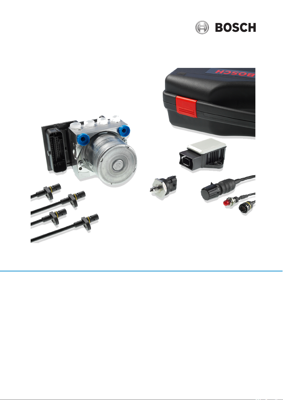
5 Included in the Kit ............................................................................................................................................. 13
5.1 Parts Overview Kit 1 ..................................................................................................................................................................... 13
5.2 Parts Overview Kit 2 ..................................................................................................................................................................... 13
5.3 Parts Overview Kit Clubsport .................................................................................................................................................... 14
5.4 Connectors Overview Kit 1 ........................................................................................................................................................ 14
5.5 Connectors Overview Kit 2 ........................................................................................................................................................ 15
5.6 Connectors Overview Kit Clubsport ....................................................................................................................................... 15
6 Optional Accessories ......................................................................................................................................... 16
6.1 MSA Box II ........................................................................................................................................................................................ 16
6.2 Wheel Speed Signal Splitter ...................................................................................................................................................... 16
6.3 Data Logger C 70 .......................................................................................................................................................................... 17
6.4 Displays DDU 9 and DDU 10 .................................................................................................................................................... 17
7 Assembling the Parts ........................................................................................................................................ 18
7.1 Hydraulic Power Unit with attached Control Unit ............................................................................................................ 18
7.2 Brake Pressure Sensor ................................................................................................................................................................. 19
7.3 Wheel Speed Sensors .................................................................................................................................................................. 19
7.4 Encoder Wheel ............................................................................................................................................................................... 20
7.5 Distance between the Sensor and the Encoder Wheel .................................................................................................. 20
7.6 Gyro/Acceleration Sensor .......................................................................................................................................................... 20
7.7 ABS Map Switch ............................................................................................................................................................................. 21
7.8 ABS Warning Light (MIL) ............................................................................................................................................................ 21
7.9 Diagnosis Interface ....................................................................................................................................................................... 22
7.10 Brake Light Switch ......................................................................................................................................................................... 22
7.11 Brake Lines ....................................................................................................................................................................................... 23
7.12 General: Brake Calipers ............................................................................................................................................................... 23
8 Laptop Communication .................................................................................................................................... 24
9 Programming and Diagnosis Software ........................................................................................................... 25
9.1 Installing the Programming and Diagnosis Software ..................................................................................................... 25
9.2 Features of the Programming and Diagnosis Software ................................................................................................. 27
10 Appendix ............................................................................................................................................................ 38
10.1 Startup Checklist ............................................................................................................................................................................ 38
10.2 CAN Protocol .................................................................................................................................................................................. 40
11 Offer Drawing: Hydraulic Power Unit with attached Control Unit .............................................................. 43
2 / 54 ABS M4 Manual Bosch Motorsport

Table of Contents
12 Offer Drawing: Brake Pressure Sensor ............................................................................................................ 44
13 Mounting Instructions: Brake Pressure Sensor .............................................................................................. 45
14 Offer Drawing: Wheel Speed Sensor ............................................................................................................... 46
15 Offer Drawing: Gyro/Acceleration Sensor ...................................................................................................... 47
16 Wiring Diagram ................................................................................................................................................. 48
17 Wiring Diagram ABS M4 Clubsport ................................................................................................................. 49
18 Wiring Harness .................................................................................................................................................. 50
19 Wiring Harness Clubsport ................................................................................................................................ 51
Bosch Motorsport ABS M4 Manual 3 / 54

1
2
4
3
5
6
7
8
9
10
19
20
23
24
16
12
13
14
15
21
22
25
26
27
28
29
18
30
31
32
33
34
35
36
40
41
42
43
44
45
46
17
to RaceLab Sport analyzing tool
to ABS calibration and diagnostic software RaceABS
47
37
38
Logging device
39
11
Brake lines
1 Brake pressure front right
2 Brake pressure front left
3 Brake pressure rear right
4 Brake pressure rear left
5 Brake pressure master cylinder front
6 Brake pressure master cylinder rear
Measuring channels
7 Wheel speed front right
8 Wheel speed front left
9 Wheel speed rear right
10 Wheel speed rear left
11 Signal brake pressure sensor
12 Signal function switch
13 ABS Warning Lamp (MIL)
14 K-line to diagnostic connector
15 CAN-Link to C Sport memory
16 Signal longitudinal acceleration via CAN
17 Signal lateral acceleration sensor via CAN
18 Yaw signal via CAN
Measuring channels optional
19 Signal brake pressure front right
20 Signal brake pressure front left
21 Signal brake pressure rear right
22 Signal brake pressure rear left
23 Brake pressure master cylinder front
24 Brake pressure master cylinder rear
Hardware
25 Wheel speed sensor front right
26 Wheel speed sensor front left
27 Wheel speed sensor rear right
28 Wheel speed sensor rear left
29 ABS ECU & hydraulic modulator
30 Brake master cylinder front
31 Brake master cylinder rear
32 Yaw/ acceleration sensor
33 ABS map switch
34 ABS Warning lamp (MIL)
35 Diagnostic connector and data download via CAN
36 Brake switch
37 Brake pedal
38 Brake balance adjustor
39 Brake pressure sensor
Optional equipment
40 Logging device
41 Pressure sensor master cylinder front
42 Pressure sensor master cylinder rear
43 Pressure sensor front right
44 Pressure sensor front left
45 Pressure sensor rear right
46 Pressure sensor rear left
47 Steering angle potentiometer
1 | System Overview
System Overview
1
4 / 54 ABS M4 Manual Bosch Motorsport

Before Use
Brake Performance
Vehicle Stability During Braking
Race ABS
Operating Range
Standard OEM ABS
Operating Range
2
Read these instructions carefully and follow the recommendations for use step
by step. We are happy to give you additional notes and explanations. Our con‐
tact information is on the back cover of this manual.
Before Use | 2
2.1
Safety Information
The ABS M4 Kit was developed for use by professionals and requires in‐depth
knowledge of automobile technology and experience in motorsport. Using the
system does not come without its risks.
It is the duty of the customer to use the system for motor racing purposes only
and not on public roads. We accept no responsibility for the reliability of the sys‐
tem on public roads. In the event that the system is used on public roads, we
shall not be held responsible or liable for damages.
Any maintenance or repair must be performed by authorized and qualified per‐
sonnel approved by Bosch Motorsport.
All system parts are designed to work together and may not be replaced with
similar parts without our expressed permission (this includes the wiring harness).
For first time purchases, each team or owner must purchase a complete kit which
includes a wiring harness. Spare parts may be purchased after a complete kit has
been purchased. The use of unauthorized parts or wiring harnesses will not be
supported by Bosch Motorsport; additionally the system cannot be guaranteed
to work properly and/or without limitations.
It is essential that the predefined Bosch Motorsport assembly guidelines are
complied with, see section Assembling the Parts [} 18], the system to run
properly. This applies above all for installing the MIL (malfunction indication
lamp) within the driver's range of visibility.
Bosch Motorsport ABS M4 Manual 5 / 54
2.2
ABS in Motorsport
The ABS function is a compromise between drivability and braking performance.
Drivability is the primary focus for passenger based vehicles. The ABS is designed
to keep the passenger vehicle maneuverable and stable under any circumstances
and under any conceivable driving conditions.
In a motorsport context, this compromise shifts towards braking performance, as
experienced drivers can still control a slightly unstable vehicle. Together with dif‐
ferent tire structures and higher braking potential, a racecar is capable of greatly
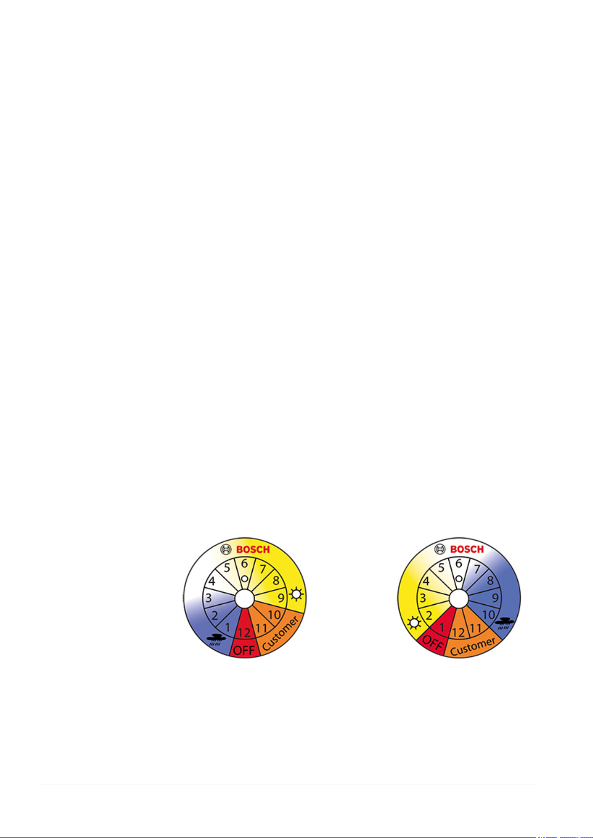
ABS scale standard ABS scale alternative
2 | Before Use
increased deceleration rates. To consider different chassis tuning and tires ABS
M4 has nine control settings. They differ from each other belonging start and
process of control. With this, the driver can choose the best setting for his vehi‐
cle. Furthermore, the ABS M4 provides the opportunity to program two individu‐
al control settings for you vehicle. For calibration drives, the ABS function can be
deactivated separately, whereby all ABS sensor signals are transmitted and pro‐
cessed furthermore.
2.3
2.4
Principle of Operation
ABS M4 is suitable for front-wheel, rear-wheel and four-wheel drive vehicles.
It is based on a series production ABS and adapted in years of development work
to meet motorsport requirements, e.g. FIA requirements for using only eight ac‐
tive valves.
The ABS prevents the wheels from locking during braking. It does this by con‐
stantly measuring the individual wheel speeds and comparing them with the ve‐
hicle speed predicted by the system. If, during braking, the measured wheel
speed deviates from the system's predicted vehicle speed, the ABS controller
takes over, correcting the brake force to keep the wheel at the optimum slip level
and so achieving the highest possible deceleration rate. This is carried out sepa‐
rately for each wheel.
When the brake force is reduced by the ABS, brake fluid is released from the
brake caliper and fed into the pressure reservoir of the hydraulic power unit of
the ABS. The hydraulic power unit then feeds the fluid back into the master cylin‐
der via a piston pump driven by an electric motor. The driver can hear this return
pumping of the brake fluid and feel the response of the brake pedal.
Features
Note: In the following, we only refer to the Standard ABS scale. The Alternative
ABS scale is only used for DF11S, 1 Mbaut. You can use the Alternative ABS scale
if your ABS M4 is switched off in position 1.
▪ Nine different control settings, selectable via a switch in the cockpit (position
1‐9)
The ABS map switch in the cockpit enables the driver to select various control
settings stored in the control device. Using the standard ABS scale, it starts
with switch position 1 for the most sensitive controller setting (e.g. heavy rain
condition). The response characteristic gets more progressive from position
6 / 54 ABS M4 Manual Bosch Motorsport

Before Use | 2
to position. Finally, with switch position 9 the most progressive effect is ach‐
ieved. With the different control settings, the driver can select the preferable
map for the vehicle, the racetrack and weather. Comment: The most progres‐
sive braking characteristics leads not necessarily to best lap times. Rather the
position that allows the driver to feel the most comfortable will be the most
desirable position.
▪ Two additional vehicle‐specific control maps storable (position 10 and 11)
Switch positions 10 and 11 are pre‐dated with a copy of position 9. Bosch‐
Engineers can calibrate them individually for each customer.
▪ Switch off ABS functions for calibration drives (position 12).
You can switch off the ABS functions by switching to position 12. This can be
very helpful, e.g. for calibration of the brake balance adjuster. All ABS sensor
signals will still be communicated. Every older ABS M4 can be updated to this
function. During warm‐up we recommend to choose position 12. Since soft‐
ware status V1017 no error entry takes place any longer.
▪ Measuring vehicle dynamics
Due to specially‐adapted chassis and tires, motor racing vehicles allow for
significantly higher longitudinal and lateral acceleration rates than series pro‐
duction vehicles. The ABS M4 is designed to intervene after a corresponding
amount of time. Our ABS M4 sensors constantly measure vehicle acceleration
and rotation rates as well as the pressure of the front brake circuit. The ABS
control algorithms at the front brake circuit rely on the measurements of ac‐
celeration and pressure.
▪ Programming and diagnosis software
Each ABS M4 is preprogrammed with specific data related to the vehicle,
such as vehicle mass, wheelbase, track width, tire rolling circumference, etc.
Should the vehicle data change at any time, you can adapt the system set‐
tings by using the RaceABS diagnostic software. You find the software for
free download on our website www.bosch‐motorsport.de.
▪ There are further features to the software:
▪ Performing a system function test
The system function test can diagnose the functional capability and profes‐
sional assembly of any part, without having to move the vehicle.
▪ Reading data from the error log
Any missing part or incorrectly connected electrical connection is signaled by
a lit MIL (Malfunction Indication Lamp). In the error log you can read and an‐
alyze what errors have set the MIL and then delete the errors after the issue
has been resolved.
▪ Repair Bleeding Wizzard
Step‐by‐step instructions will guide you through bleeding the ABS unit.
▪ Connectivity for data loggers and display
You can connect a data logger (e.g. the C 50 from Bosch Motorsport) to the
ABS‐Wiring‐Harness via CAN. The CAN Bus can give you wheelspeeds and
other readings from the system. All ABS M4 CAN messages can be displayed
on any programmable, CAN‐compatible display (e.g. the DDU 7 from Bosch
Motorsport).
Bosch Motorsport ABS M4 Manual 7 / 54

2 | Before Use
▪ Switch on and off the system with a switch in the cockpit
You can switch the system ON or OFF by moving the switch in the cockpit for
one time.
▪ Reset the System with a switch in the cockpit
You can reset the system by moving the switch to the position OFF and then
directly again ON.
8 / 54 ABS M4 Manual Bosch Motorsport

Technical Data
3
Mechanical Data
Hydraulic unit with attached ECU
Serial housing, dust‐ and damp‐proof
Vibration damped circuit board
38 pin connector
2 hydraulic valves per wheel
2 brake circuits (front and rear)
2 hydraulic high pressures pumps
2 hydraulic accumulators 3 cm3/each
Standard fittings 2 x master cylinders M12 x 1
4 x brake cylinders M10 x 1
Size 125 x 80.3 x 129.6 mm
Technical Data | 3
Weight about 1,850 g
Operating temperature ‐30 to 130°C
Max. shock 50 g less than 6 ms
Electrical Data
Supply voltage 8 to 16 V, max. 26 V for 5 min
Max. peak voltage 35 V for 200 ms
Power consumption 8 W stand‐by, 230 W in operation
Inputs
4 active wheel speed DF11
Brake pressure (front brake circuit)
Longitudinal acceleration, lateral acceleration, yaw rate
9 adjustment settings applicable for OEMSs (Pos. 1‐9)
2 adjustment settings applicable for Temas (Pos. 10 and 11)
ABS function can be deactivated (Pos. 12)
Brake light switch
Outputs
ABS warning light (MIL)
Communication
CAN interface
Content of Kit and Weights
Hydraulic unit with attached ECU About 1,850 g
Pressure sensor About 40 g
Yaw/acceleration sensor About 60 g
Bosch Motorsport ABS M4 Manual 9 / 54

3 | Technical Data
12 position function switch About 50 g
4 wheel speed sensors DF11 standard About 50 g/each
ABS warning light (MIL) About 50 g
Vehicle specific wiring harness with mo‐
Depends on version
torsport connectors
Clubsport wiring harness About 1,500 g
Mounting and vibration‐damping
About 80 g
boards
Mounting board for hydraulic unit About 210 g
Optional Accessories
Data logger C 50 F 02U V01 164‐01
Data logger C 60 F 02U V00 875‐03
Display DDU 7 F 02U V01 130‐04
Communication interface MSA Box II F 02U V00 327‐02
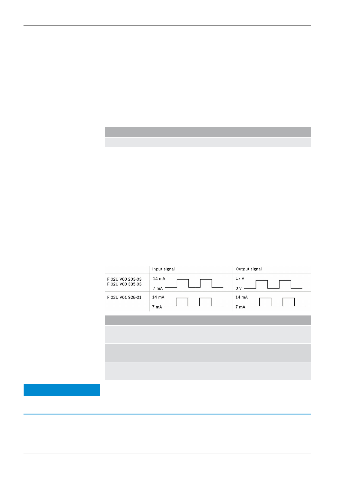
Wheel speed signal splitters
Quad with 2 motorsport connectors F 02U V00 203‐03
Quad with 1 motorsport connector F 02U V00 335‐03
Porsche 991 with 1 motorsport connec‐
tor
F 02U V01 928‐01
Field of application
ABS for front‐wheel, rear‐wheel or four‐
wheel drive racing cars
Part numbers
ABS M4‐Package 1 (incl. wiring harness with
motorsport connectors, individual layout
depending on customer requirements,
wheel speed sensors with production‐type
connectors)
ABS M4‐Package 2 (incl. wiring harness with
motorsport connectors, individual layout
depending on customer requirements,
wheel speed sensors with motorsport con‐
nectors)
ABS M4‐Package Clubsport (incl. wiring har‐
ness with motorsport connectors, wheel
speed sensors with serial connectors)
F 02UV00 289‐01
F02U V00 290‐01
1MBaud:
F 02U V01 289‐49 (DF11S)
F 02U V00 543‐13 (DF11i)
500 kBaud:
F 02U V01 289‐48 (DF11S)
F 02U V00 543‐12 (DF11i)
10 / 54 ABS M4 Manual Bosch Motorsport

Adaptations to Your Vehicle | 4
Adaptations to Your Vehicle
4
Physical vehicle data
For optimum brake performance, each M4 unit has to be customized to suit the
vehicle in which it is to be used. To do this, the system can be programmed by
the user with certain data, such as the vehicle weight, vehicle dimensions, wheel
circumference, and wheel weight. The system then uses this data as basis for cal‐
culation. Bosch can also program this data ahead prior to delivery on request,
however, it is very important that you calibrate or verify the data prior to operat‐
ing the vehicle.
You can find a form to fill in your vehicle data on www.bosch‐motorsport.com.
This form should be provided to you by your dealer with the order of the kit, if
the kit shall be programmed by Bosch.
Wiring harness
Each ABS system is delivered with a wiring harness that we have specifically cre‐
ated in accordance with customer requests.
With every Clubsport ABS you receive an appropriate wiring harness, which is not
specifically created. Please see Wiring Harness Clubsport [} 51].
System environment and related requirements
Is the ABS system being used as a closed stand-alone system? Or is it networked with a control unit?
If the system is networked with a standard control unit, we recommend that you
use our speed/acceleration sensor with a CAN rate of 500 Kbaud/s to avoid com‐
patibility issues.
If the system is networked with a motorsport control unit or used as self‐suffi‐
cient stand‐alone‐system, we recommend that you use our speed/acceleration
sensor with a CAN rate of 1 Mbaud/s. This version features a greater measuring
range.
Was or is the vehicle already fitted with an ABS system? Was or is it an old
BOSCH ABS system?
ABS M4 requires signals from differential dual Hallsensors such as the Bosch
DF11 or similar to function correctly. These sensor types are used in new vehicles
for ABS and ESP® systems and can be carried over for the ABS M4. The signal
level of conventional speed sensors, as found in old series‐production ABS sys‐
tems for example, is not compatible with the ABS M4; it is therefore not possible
to carry over conventional speed sensors as signal transmitters.
If your vehicle contains an older ABS system, you have to remove the wheel
speed sensors and replace them by the sensors includes in the package to be
able to use theABS M4.
If you are fitting your vehicle with an ABS system for the first time, you may need
an encoder wheel for each wheel and a sensor mount to record the wheel
speeds. Please pay attention to the fitting position of the wheel speed sensors.
Do the wheel speed signals also need to be made available to other control
Bosch Motorsport ABS M4 Manual 11 / 54
units?

4 | Adaptations to Your Vehicle
We have developed a wheel speed signal splitter that converts the signals in such
a way that they can also be processed by peripheral engine control units and da‐
ta logging systems. The splitter provides an input signal like as it is shown in the
diagram in chapter Wheel Speed Signal Splitter [} 16]. This module can be
used, for traction control, display and gear units. For ordering information see al‐
so Wheel Speed Signal Splitter [} 16].
12 / 54 ABS M4 Manual Bosch Motorsport

Included in the Kit
5
The following chapter introduces the contents of the different kits.
Included in the Kit | 5
5.1
Parts Overview Kit 1
ABS M4 Kit 1 with part number F 02U V00 289‐01 always includes a wiring har‐
ness. ABS M4 Kit 1 includes the following parts, which are also available as indi‐
vidual spare parts (Hydraulic power unit only in exchange):
Description Part Number
Hydraulic unit with attached ECU Standard (for DF11S wheel speed sen‐
sors): F 02U V00 866‐01
Alternativ (for DF11i wheel speed sen‐
sors): F 02U 002 487‐01
Mounting plate for hydraulic unit with
attached ECU
Brake pressure sensor 0 261 B08 072‐08
4 wheel speed sensors DF11 0 265 008 022
Yaw/acceleration sensor Standard 1 MBaud/s: 0 265 005 838
Damping plate for yaw/acceleration
sensor
0 265 Y44 520‐01
0 285 007 871 (old model)
Alternative 500 kBaud/s:
F 02U V00 049‐02
1 271 032 390
5.2
12‐position ABS map switch F 02U V00 111‐03
ABS warning light (MIL) with electronic
control module
Incl. wiring harness with motorsport
connectors, customer‐specific layout,
wheel speed sensors with production‐
type connectors.
Bulb: F 02U V00 112‐01
LED: F 02U V00 112‐02
Similar to connection diagram
F 02U S00 043‐09, see Wiring Diagram
[} 48]
Parts Overview Kit 2
ABS M4 Kit 2 includes all the parts from Kit 1, with the exception of a different
wiring harness with motorsport connectors for the wheel speed sensors.
Bosch Motorsport ABS M4 Manual 13 / 54

5 | Included in the Kit
5.3
Parts Overview Kit Clubsport
There are a few variants of the ABS M4 Kit Clubsport available:
Description Part Number
ABS M4 Kit Clubsport (1 MBaud, DF11S) F 02U V01 289‐49
ABS M4 Kit Clubsport (500 kBaud,
DF11S)
ABS M4 Kit Clubsport (1 MBaud, for
DF11i)
ABS M4 Kit Clubsport (500 kBaud, for
DF11i)
ABS M4 Kit includes all parts from Kit 1, but a different wiring harness, which
cannot be modified. By default the wiring harness includes a 60 Ohm terminal re‐
sistance, which can be replaced customer specific by a 120 Ohm or deleted com‐
pletely, see wiring diagram ABS M4 Clubsport.
Description Part Number
Wiring harness Clubsport F 02U V01 917‐01
See also
F 02U V01 289‐48
F 02U V00 543‐13
F 02U V00 543‐12
5.4
2 Wiring Diagram ABS M4 Clubsport [} 49]
Connectors Overview Kit 1
ABS M4 Kit 1 with part number F 02U V00 289‐01 includes the following connec‐
tors, which are also available as individual spare parts:
Connector for Part Number
Attached control unit connector Standard
wire departure on top: F 02U B00
238‐01
wire departure on top 90°: F 02U B00
238‐01
Alternativ
wire departure on bottom: F 02U B00
237‐01
wire departure on bottom 90°: F 02U
B00 237‐01
Brake pressure sensor
Compact 3‐pin connector
D 261 205 335‐01
12‐positon ABS map switch
ASL 006‐05SE‐HE
ABS warning light (MIL)
ASL 006‐05SA‐HE
14 / 54 ABS M4 Manual Bosch Motorsport
F 02U 000 230‐01
F 02U 000 226‐01

Connector for Part Number
Included in the Kit | 5
Wheel speed sensor
Tyco 2‐pin connector
Yaw/acceleration sensor
Tyco 4‐pin connector
Diagnosis connector K‐line F 02U 000 258‐01
Wheel speed signal splitter ABS‐sided
AS 612‐35 SN
Jumper connector for wiring harness
without wheel speed module
AS 112‐35 PN
Data‐logger intersection
ASL 006‐05SD HE
F 02U B00 241‐01
F 02U B00 435‐01
F 02U 000 443‐01
F 02U 000 304‐01
or
F 02U B00 354‐01
F 02U 000 229‐01
Mating connector overview ABS M4‐Paket 1
Connector for Part Number
Brake pressure sensor D 261 205 335‐01
12‐position ABS map switch F 02U 000 230‐01
ABS warning light (MIL) F 02U 000 226‐01
5.5
5.6
Wheel speed sensor F 02U B00 241‐01
Yaw/acceleration sensor F 02U B00 435‐01
Connectors Overview Kit 2
ABS M4 Kit 2 with part number F 02U V00 290‐01 includes a harness with all the
connectors from Kit 1, with the exception of different connectors for the wheel
speed sensors:
Connector for Part Number
Wiring harness sided
ASL 006‐05PN‐HE
Sensor sided
ASL 606‐05SN‐HE
F 02U 000 342‐01
F 02U 000 416‐01
Connectors Overview Kit Clubsport
ABS M4‐Kit Clubsport with part numbers F 02U V01 289‐49, F 02U V01 289‐48, F
02U V00 543‐13 or F 02U V00 543‐12 includes all connectors of Kit 1, but differ‐
ently the encoding connector:
Connector for Part Number
Encoding connector CAN harness‐side
Super Seal 2‐pole
Encoding connector CAN with a 60 Ohm
resistor
Super Seal 2‐pole
Bosch Motorsport ABS M4 Manual 15 / 54
F 02U B00 246‐01
F 02U B00 247‐01
6 | Optional Accessories
Optional Accessories
6
The following chapter introduces the optional accessories for the ABS Kit, which
are not included in the kit.
6.1
6.2
MSA Box II
ABS M4 communicates with your laptop via the MSA Box II. It has a USB connec‐
tion to the laptop and a motorsport connector to interface with the ABS M4 wire
harness. Communication via K‐line.
Description Part Number
MSA Box II F 02U V00 327‐03
Wheel Speed Signal Splitter
The ABS M4 from Bosch Motorsport relies on specifically‐designed wheel speed
signals, delivered exclusively from active speed sensors, e.g. from the Bosch DF11
family. These sensors are used in current ABS and ESP® systems. The four speed
sensors included in the ABS M4 Kit meet this classification. The signal of a regular
speed sensor, as found in older series production ABS applications, is not com‐
patible withv; they could not be used as signal providers. It is an “open collector”
signal which grounds the voltage at the ECU input with every flank. Bosch Motor‐
sport has developed a wheel speed signal splitter that converts the sensor sig‐
nals in such a way that they can be processed by peripheral ECUs and data re‐
cording systems. This signal splitter is available e.g. for measuring vehicle speed
or traction control. The signals of the different wheel speed signal splitters:
Description Part Number
Notice
Wheel speed signal splitter quad with 1
motorsport connector
Wheel speed signal splitter quad with 2
motorsport connectors
Wheel speed signal splitter Porsche 991
with 1 motorsport connector
The wheel speed signal splitter with 1 connector cannot be
used with the standard wiring loom design without changes in
F 02U V00 335‐03
F 02U V00 203‐03
F 02U V01 928‐01
the layout.
16 / 54 ABS M4 Manual Bosch Motorsport

Optional Accessories | 6
6.3
6.4
Data Logger C 70
All ABS M4 data can be stored on a CAN‐compatible data logger. We recom‐
mend to use our C 70 data logger for storing and analyzing ABS M4 data.
Bosch Motorsport provides a standardized CAN log in DBC format for analyzing
recorded CAN data. A reduced version of the dbc‐file could be found at our
homepage www.bosch‐motorsport.com.
Description Part Number
Data Logger C 70 F 02U V02 302‐01
Displays DDU 9 and DDU 10
The DDU 9 and DDU 10 displays have up to 3 GB of onboard data storage and
can be used as a logger.
Description Part Number
Display DDU 9 F 02U V02 300‐02
Display DDU 10 F 02U V02 659‐01
Bosch Motorsport ABS M4 Manual 17 / 54
 Loading...