

Bosch AAS-009-0CS, AAS-012-0CS, AAS-018-1CS, AAS-009-1CS, AAS-012-1CS Installation Manual
...
Bosch Split-Type Ductless Air Conditioner / Heat Pump
Climate 5000 AA Series
Installation Manual

|
2
Bosch Climate 5000 AA Series Split Type Ductless Air Conditioner / Heat Pump Installation Manual
01.2017 | Bosch Thermotechnology Corp.Data subject to change

Installation Manual Bosch Climate 5000 AA Series Split Type Ductless Air Conditioner / Heat Pump | 3
Table of Contents
1 Key to symbols and safety instructions 4
1.2 Safety 4
2 Components 6
3 Installation Summary - Indoor Unit 7
4 Unit parts 8
5 Indoor unit installation 9
6 Outdoor unit installation 17
7 Refrigerant piping connection 22
7.1 Connection instructions – refrigerant piping 22
7.2 Connecting piping to indoor unit 25
7.3 Connecting tubing to outdoor unit 25
8 Air evacuation 26
8.1 Preparations and precautions 26
8.2 Evacuation instructions 26
8.3 Adding refrigerant 27
9 Electrical and gas leak checks 28
9.1 Electrical safety checks 28
9.2 Gas leak checks 28
10 Test run 29
10.1 Before Test Run 29
10.2 Test run instructions 29
11 Disposal guidelines 30
12 Wiring diagrams 31
Bosch Thermotechnology Corp. | 01.2017
Data subject to change
|
4
Bosch Climate 5000 AA Series Split Type Ductless Air Conditioner / Heat Pump Installation Manual
1 Key to symbols and safety instructions
1.1 Key to symbols
Warnings
Warnings in this document are identifi ed by a
warning triangle printed against a grey background.
Keywords at the start of a warning indicate the type and seriousness
of the ensuing risk if measures to prevent the risk are not taken.
The following keywords are defi ned and can be used in this document:
DANGER indicates a hazardous situation which, if not avoided, will result in
death or serious injury.
WARNING indicates a hazardous situation which, if not avoided, could
result in death or serious injury.
CAUTION indicates a hazardous situation which, if not avoided, could
result in minor to moderate injury.
NOTICE is used to address practices not related to personal injury.
Important information
1.2 Safety
Please read safety precautions before installation
Incorrect installation due to ignoring instructions can cause serious damage or injury.
WARNING:
Do not modify the length of the power supply cord or use an
extension cord to power the unit.
Do not share the electrical outlet with other appliances.
Improper or insufficient power supply can cause fire or
electrical shock.
WARNING:
When connecting refrigerant piping, do not let substances or
gases other than the specified refrigerant enter the unit. The
presence of other gases or substances will lower the unit’s
capacity, and can cause abnormally high pressure in the
refrigeration cycle. This can cause explosion and injury.
WARNING: INSTALLATION REQUIREMENTS
Installation must be performed by a licensed contractor,
and per the instructions in the installation manual. Improper
installation can cause water leakage, electrical shock, or fire.
This symbol indicates important information where
there is no risk to people or property.
In North America, installation must be performed in
accordance with the requirement of NEC (National Electric
Code) and CEC (Canadian Electric Code) by licensed and
qualified personnel only.
Only contact an licensed contractor for repair or maintenance
of this unit.
Only use the included accessories, parts, and specified parts
for installation. Using non-standard parts can cause water
leakage, electrical shock, fire, and can cause the unit to fail.
Install the unit in a solid location that can support the unit’s
weight. If the chosen location cannot support the unit’s
weight, or the installation is not done properly, the unit may
drop and cause serious injury and/or damage.
01.2017 | Bosch Thermotechnology Corp.Data subject to change
Installation Manual Bosch Climate 5000 AA Series Split Type Ductless Air Conditioner / Heat Pump | 5
WARNING: ELECTRICAL
For all electrical work, follow all local and national wiring
standards, regulations, and the Installation Manual.
The power supply to the outdoor unit requires a service
disconnect at the unit. Only use a dedicated circuit. Never
share a power source connected to this system. Insufficient
electrical capacity or defects in electrical work can cause
electrical shock or fire.
For all electrical work, use the specified cables. Connect
cables tightly, and clamp them securely to prevent external
forces from damaging the terminal. Improper electrical
connections can overheat and cause fire, and may also cause
shock.
All wiring must be properly arranged to ensure that the
control board cover can close properly. If the control board
cover is not closed properly, it can lead to corrosion and
cause the connection points on the terminal to heat up, catch
fire, or cause electrical shock.
In certain functional environments, such as kitchens, server
rooms, etc., the use of specially designed air-conditioning
units is highly recommended.
If the power supply cord is damaged, it must be replaced
by the manufacturer, its service agent or similarly qualified
persons such as a licensed electrician in order to avoid a
hazard.
NOTICE: FLUORINATED GASSES [REFRIGERANT]
This air-conditioning unit contains fluorinated gasses. For
specific information on the type of gas and the amount,
please refer to the relevant label on the outdoor unit itself.
Installation, service, maintenance and repair of this unit must
be performed by a certified technician.
Product removal and recycling must be performed by a
certified technician.
If the system has a leak-detection system installed, it must be
checked for leaks at least every 12 months.
When the unit is checked for leaks, proper record-keeping of
all checks is strongly recommended.
The product must be properly grounded at the time of
installation, or electrical shock may occur.
CAUTION:
For units that have an auxiliary electric heater, do not install
the unit within 1 meter (3 feet) of any combustible materials.
Do not install the unit in a location that may be exposed
to combustible gas leaks. If combustible gas accumulates
around the unit, it may cause fire.
Do not operate your air conditioner in a wet room such as a
bathroom or laundry room. Too much exposure to water can
cause electrical components to short circuit.
CAUTION:
Install condensate drainage piping according to the
instructions in this manual. Improper condensate drainage
may cause water damage to your home and property.
Bosch Thermotechnology Corp. | 01.2017
Data subject to change
|
6
Bosch Climate 5000 AA Series Split Type Ductless Air Conditioner / Heat Pump Installation Manual
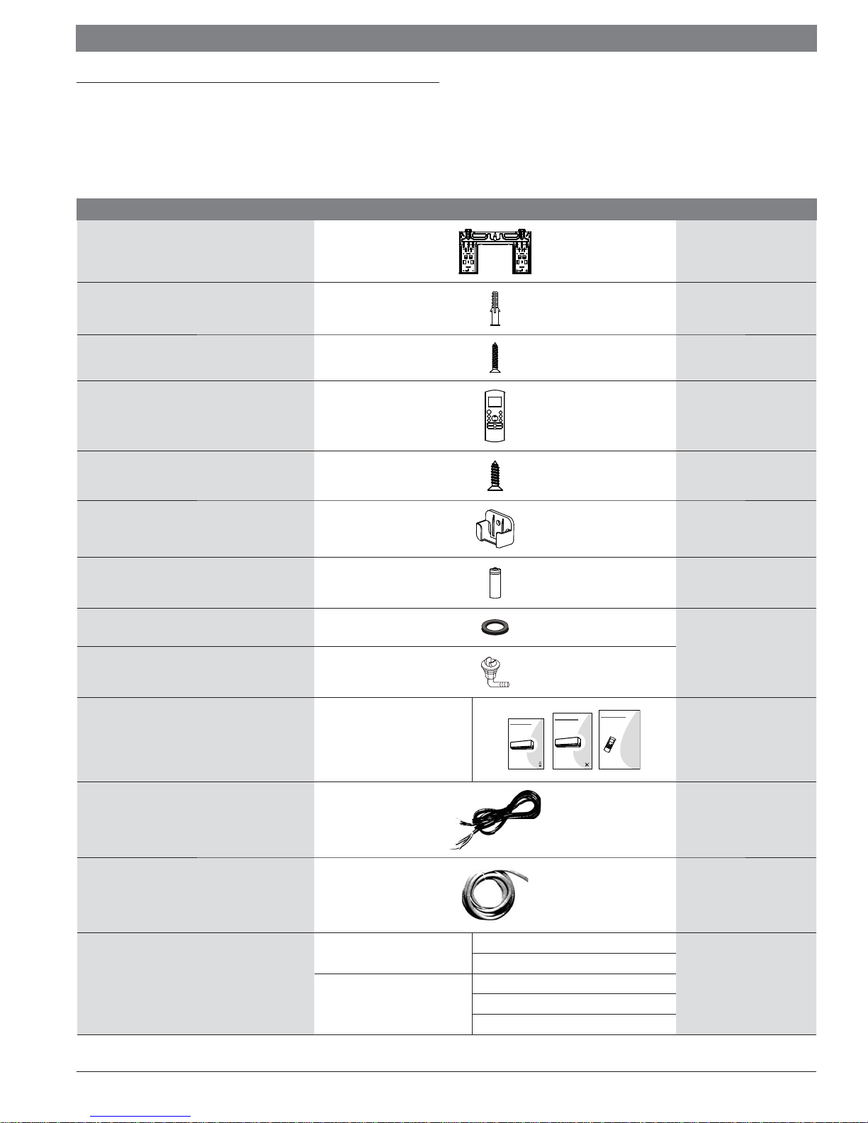
2 Components
The air conditioning / heat pump system comes with the following components. Use
all of the installation parts and components to install the air conditioner. Improper
installation may result in water leakage, electrical shock and fi re, or cause the
equipment to fail.
Name Image Quanity
Mounting plate 1
Clip anchor 5
Mounting plate fi xing screw ST3.9 X 25
Remote controller 1
Fixing screw for remote controller holder ST2.9 x 10 2
Remote controller holder 1
Dry battery AAA.LR03 2
Seal
Drain joint
INVERTER SPLIT-TYPE ROOM AIR CONDITIONER
Remote controller
illustration
Aurora Series
All Model Numbers
1 each
CS78421-548-754
CS78421-548-754
IMPORTANT NOTE:
Read this manual carefully before installing
or operating your new air conditioning
unit. Make sure to save this manual for
future reference.
Documentation
Owner's manual
Installation manual
Remote controller user manual
INVERTER SPLIT-TYPE ROOM AIR CONDITIONER
Owner’s Manual
Aurora Series
All Model Numbers
IMPORTANT NOTE:
Read this manual carefully before installing
or operating your new air conditioning
unit. Make sure to save this manual for
future reference.
INVERTER SPLIT-TYPE ROOM AIR CONDITIONER
Installation Manual
Aurora Series
All Model Numbers
CS78421-548-754
IMPORTANT NOTE:
Read this manual carefully before installing
or operating your new air conditioning
unit. Make sure to save this manual for
future reference.
5
1
Signal/power cable 1
Drain hose
Connecting pipe assembly
Table 1
Liquid side
Gas side
Φ6.35( 1/4 i n)
Φ9.52( 3/8in)
Φ9.52( 3/8in)
Φ12.7( 1/2in)
Φ 16( 5/8in)
1
Parts not included.
Piping kits are available
as an accessory.
01.2017 | Bosch Thermotechnology Corp.Data subject to change
Installation Manual Bosch Climate 5000 AA Series Split Type Ductless Air Conditioner / Heat Pump | 7
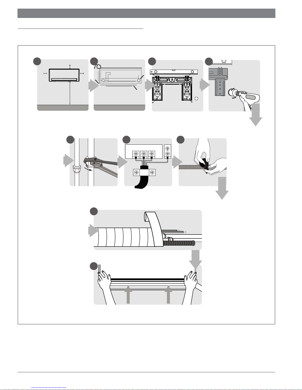
3 Installation Summary - Indoor Unit
1 2
12cm
(4.75in)
Select Installation Location
15cm (5.9in)
183cm (72in)
(Page 9)
12cm
(4.75in)
5 6 7
Connect Piping
(Page 25)
Determine Wall Hole Position
(Page 9)
123
Connect Wiring
3
(Page 14)
Attach Mounting Plate
(Page 9)
Prepare Drain Hose
4
(Page 13)
Drill Wall Hole
(Page 10)
Figure 1
8
Wrap Piping and Cable
(Page 15)
9
8
STEP
Mount Indoor Unit
(Page 16)
Bosch Thermotechnology Corp. | 01.2017
Data subject to change
|
8
Bosch Climate 5000 AA Series Split Type Ductless Air Conditioner / Heat Pump Installation Manual
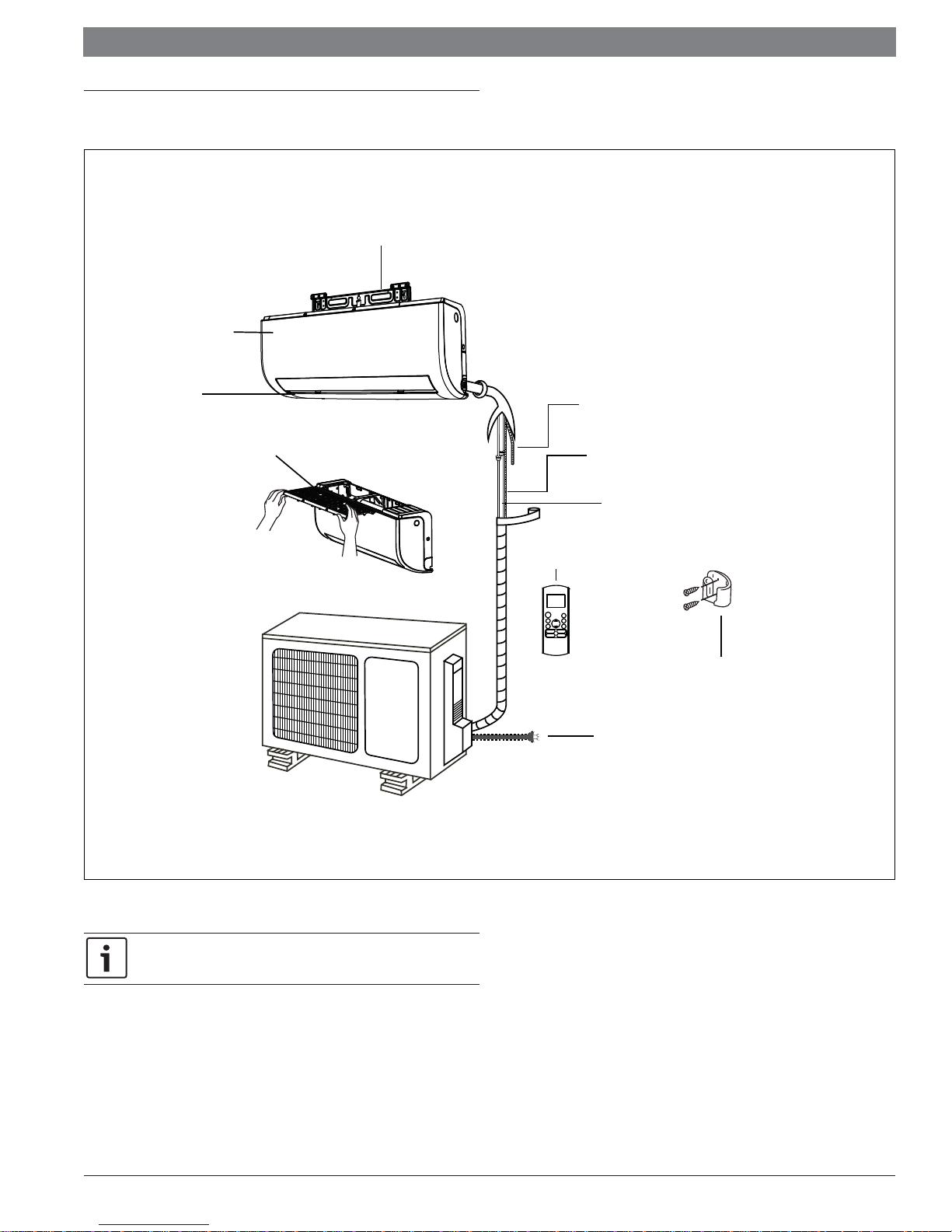
4 Unit parts
Wall Mounting Plate
Front Panel
Louver
Air filter
(pull it out)
Drainage Pipe
Signal/power Cable
(32ft cable included with indoor unit)
Refrigerant Piping
(Sold Separately)
Remote Control
Remote Holder
Outdoor Unit
Power Cable
(Required, not included with unit)
Figure 2
Illustrations in this manual are for explanatory purposes. The actual shape
of your indoor unit may be slightly diff erent. The actual shape shall prevail.
01.2017 | Bosch Thermotechnology Corp.Data subject to change
Installation Manual Bosch Climate 5000 AA Series Split Type Ductless Air Conditioner / Heat Pump | 9
5 Indoor unit installation
Before installing the indoor unit, refer to the label on the product box to
make sure that the model number of the indoor unit pairs with the model
number of the outdoor unit.
Step 1: Select installation location
Before installing the indoor unit, you must choose an appropriate location. The
following are standards that will help you choose an appropriate location for the unit.
Proper installation locations meet the following standards:
— Good air circulation
— Convenient drainage of condensate
— Noise from the unit will not disturb other people
— Firm and solid—the location will not vibrate
— Strong enough to support the weight of the unit
— A location at least three feet from all other electrical devices (e.g., TV,
radio, computer)
DO NOT install unit in the following locations:
— Near any source of heat, steam, or combustible gas
— Near flammable items such as curtains or clothing
— Near any obstacle that might block air circulation
— Near the doorway
— In a location subject to direct sunlight
Note about wall hole:
While choosing a location, be aware that you should leave ample room for
a wall hole (see Drill wall hole for connective piping step) for the signal/
power cable and refrigerant piping that connect the indoor and outdoor
units. The default position for all piping is the right side of the indoor unit
(while facing the unit). However, the unit can accommodate piping to both
the left and right.
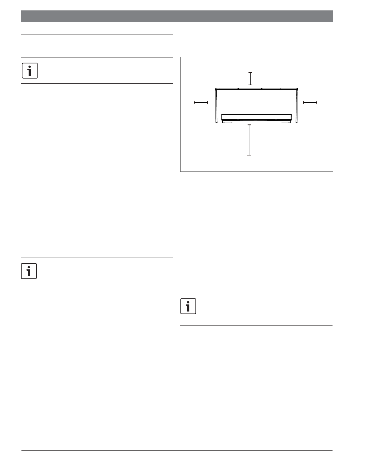
Refer to the following diagram (Fig. 3) to ensure proper distance from walls, ceiling
and fl oor:
15cm (5.9in) or more
12cm (4.75in)
or more
[recommended] 183cm (72in) or more
Figure 3
12cm (4.75in)
or more
Step 2: Attach mounting plate to wall
The mounting plate is the device on which you will mount the indoor unit.
1. Remove the screw that attaches the mounting plate to the back of the indoor
unit.
2. Place the mounting plate against the wall in a location that meets the standards
in the Select Installation Location step.(See Mounting Plate Dimensions for
detailed information on mounting plate sizes.)
3. Drill holes for mounting screws in places that:
— have studs and can support the weight of the unit
— correspond to screw holes in the mounting plate
4. Secure the mounting plate to the wall with the screws provided.
5. Make sure that mounting plate is fl at against the wall.
If the wall is made of brick, concrete, or similar material, drill 5mm-
diameter (0.2in-diameter) holes in the wall and insert the sleeve anchors
provided. Then secure the mounting plate to the wall by tightening the
screws directly into the clip anchors.
Bosch Thermotechnology Corp. | 01.2017
Data subject to change
|
10
Bosch Climate 5000 AA Series Split Type Ductless Air Conditioner / Heat Pump Installation Manual
Step 3: Drill wall hole for connective piping
You must drill a hole in the wall for refrigerant piping, the drainage pipe, and the
signal/power cable that will connect the indoor and outdoor units.
1. Determine the location of the wall hole based on the position of the mounting
plate. Refer to Mounting Plate Dimensions on the next page to help you
determine the optimal position. The wall hole should have a 65mm (2.5in)
diameter at least, and at a slightly lower angle to facilitate drainage.
2. Using a 65-mm (2.5in) core drill, drill a hole in the wall. Make sure that the
hole is drilled at a slight downward angle, so that the outdoor end of the hole
is lower than the indoor end by about 5mm to 7mm (0.2-0.275in). This will
ensure proper water drainage. (See Fig. 4)
3. Place a protective wall sleeve (not included) in the hole. This protects the
edges of the hole and will help seal it when you fi nish the installation process.
CAUTION:
When drilling the wall hole, make sure to avoid wires,
plumbing, and other sensitive components.
Indoor Outdoor
Wall
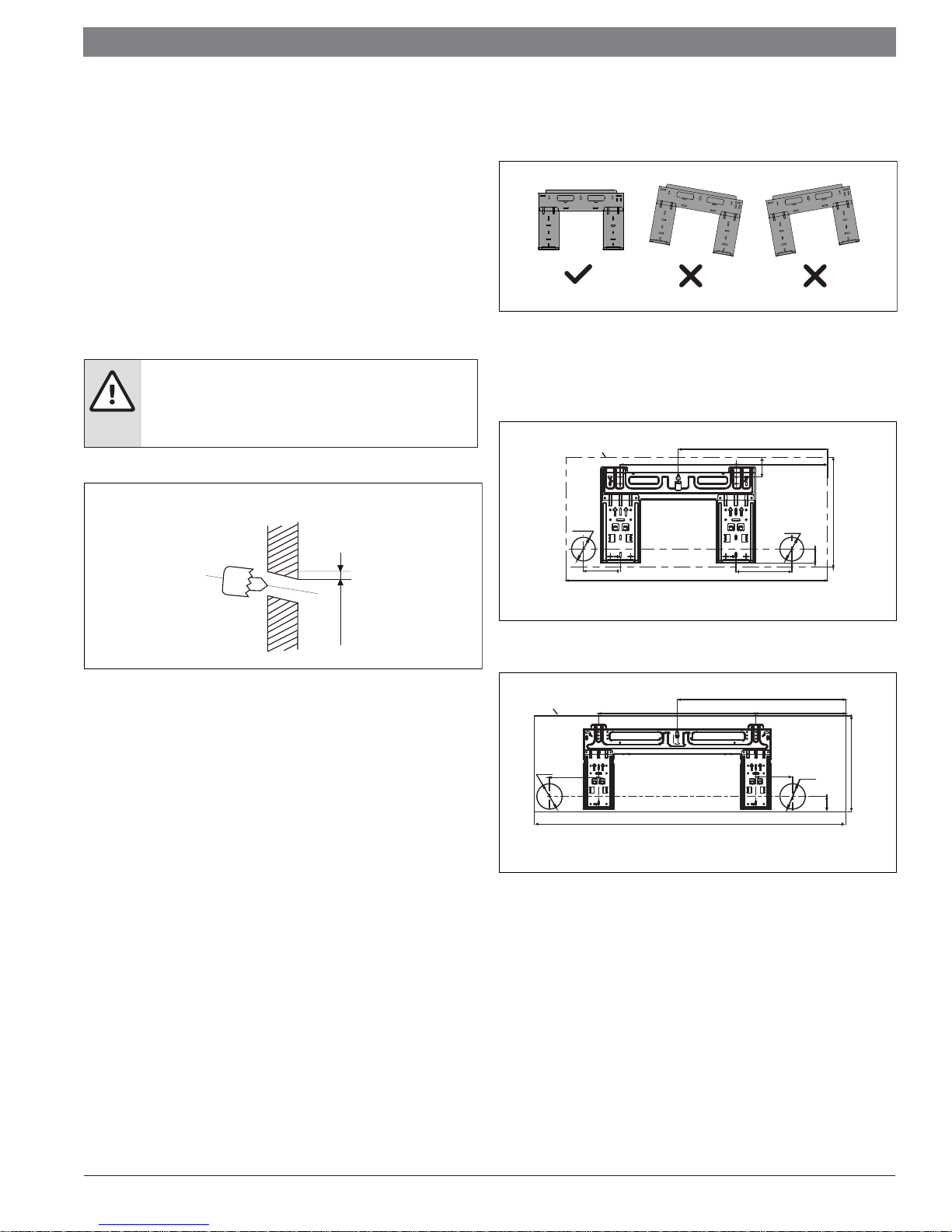
Correct orientation of Mounting Plate
Make sure the mounting plate is level.
Figure 5
Mounting plate differences
Indoor unit outline
pipe hole
φ
65mm
(2.56 in)
406.4mm(16in)
452.7mm(17.8in)
249mm(9.8in)
54mm(2.1in)
pipe hole
φ
65mm
(2.56 in)
302mm(11.9in)
mm
7-5
(0.2-0.3in)
Figure 4
Mounting plate dimensions
Diff erent models have diff erent mounting plates. In order to ensure that you have
ample room to mount the indoor unit, the diagrams to the right show diff erent types
of mounting plates along with the following dimensions:
Width of mounting plate
Height of mounting plate
Width of indoor unit relative to plate
Height of indoor unit relative to plate
Recommended position of wall hole (both to the left and right of mounting
plate)
Relative distances between screw holes
Figure 6
Figure 7
Indoor unit outline
pipe hole
φ
65mm
(2.56 in)
174mm
(6.85in)
805mm(31.7in)
153mm(6in)102mm(4in)
9k & 12k Btuh Models
558mm(21.97in)
1106mm(43.5in)
599mm(23.6in)
18k & 24k Btuh Models
320mm(12.60in)
pipe hole
130mm
φ
65mm
(5.12in)
(2.56 in)
39mm(1.5in)
342mm(13.5in)
55mm(2.17in)
01.2017 | Bosch Thermotechnology Corp.Data subject to change

Installation Manual Bosch Climate 5000 AA Series Split Type Ductless Air Conditioner / Heat Pump | 11
Step 4: Prepare refrigerant piping
The refrigerant piping is inside an insulating sleeve attached to the back of the unit.
You must prepare the piping before passing it through the hole in the wall. Refer to
the Refrigerant Piping Connection section of this manual for detailed instructions on
pipe flaring and flare torque requirements, technique, etc.
Refrigerant piping can exit the indoor unit from four diff erent angles:
Left-hand side
Left rear
Right-hand side
Right rear
Refer to Fig. 8 for details
Figure 9
30-50mm
(1.2-1.95in)
Move to left or right
Step 2: Prepare refrigerant piping:
1. Disassemble the louver:
30-50mm
(1.2-1.95in)
Rear of indoor unit
Figure 8
NOTICE:
Be extremely careful not to crimp or damage the piping while
bending them away from the unit. Any deformations in the
piping will affect the unit’s performance.
If refrigerant piping is already embedded in the wall, do the following:
Step 1: Hook the indoor unit on the mounting plate:
Keep in mind that the hooks on the mounting plate are smaller than the holes
on the back of the unit. If you fi nd that you don’t have ample room to connect
embedded pipes to the indoor unit, the unit can be adjusted left or right by
about 30-50mm (1.25-1.95in), depending on the model. (See Fig. 9)
Figure 10
2. Open and fi x the position of the panel. First, unscrew the two screws
shown in the picture below(see Fig.11).
Figure 11
Bosch Thermotechnology Corp. | 01.2017
Data subject to change
 Loading...