

Bosch A4VG A4VG 32 Instruction Manual
Axial piston variable pump
A4VG
Series 32
Instruction manual
RE 92003-01-B/12.2015
Replaces: 04.2008
English

© BoschRexrothAG2016. All rights reserved,
also regarding any disposal, exploitation,
reproduction, editing, distribution, as well as in
the event of applications for industrial property
rights.
The data specified within only serves to describe
the product. No statements concerning a certain
condition or suitability for a certain application
can be derived from our information. The
information given does not release the user from
the obligation of own judgment and verification.
It must be remembered that our products are
subject to a natural process of wear and aging.
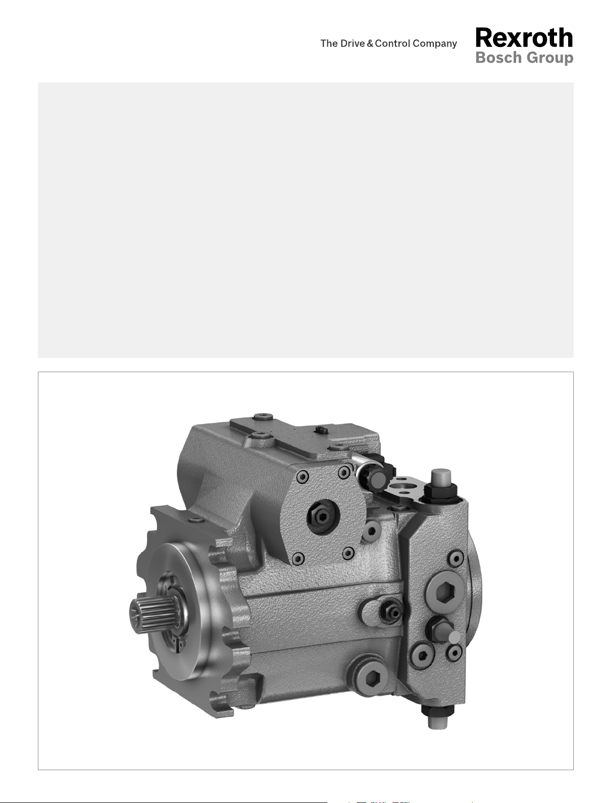
The cover shows an example application. The
product delivered may differ from the image
on the cover.
The original instruction manual was created in
the German language.

Contents 3/68
Contents
1 About this documentation 5
1.1 Validity of the documentation 5
1.2 Required and supplementary documentation 5
1.3 Display of information 6
1.3.1 Safety instructions 6
1.3.2 Symbols 7
1.3.3 Designations 7
1.3.4 Abbreviations 8
2 Safety instructions 9
2.1 About this chapter 9
2.2 Intended use 9
2.3 Improper use 9
2.4 Personnel qualifications 10
2.5 General safety instructions 11
2.6 Product-specific safety instructions 12
2.7 Personal protective equipment 15
3 General instructions on damage to property and the product 16
4 Scope of delivery 19
5 About this product 20
5.1 Performance description 20
5.2 Product description 20
5.2.1 Layout of the axial piston unit 20
5.2.2 Functional description 21
5.3 Bypass function 22
5.3.1 Bypass function size 28 to 56 23
5.3.2 Bypass function size 71, 90 24
5.3.3 Bypass function size 125 to 180 26
5.4 Product identification 27
6 Transport and storage 28
6.1 Transporting the axial piston unit 28
6.1.1 Transporting by hand 28
6.1.2 Transporting with a lifting device 28
6.2 Storing the axial piston unit 30
7 Installation 32
7.1 Unpacking 32
7.2 Installation conditions 32
7.3 Installation position 34
7.3.1 Below-reservoir installation (standard) 35
7.3.2 Above-reservoir installation 36
7.4 Installing the axial piston unit 37
7.4.1 Preparation 37
7.4.2 Dimensions 38
7.4.3 General instructions 38
7.4.4 Installation with coupling 39
7.4.5 Installation on a gearbox 40
7.4.6 Completing installation 40
RE 92003-01-B/12.2015, A4VG Series 32, Bosch Rexroth AG

4/68
Contents
7.4.7 Changing the lever position of the HW control 42
7.4.8 Hydraulically connecting the axial piston unit 42
7.4.9 Electrically connecting the axial piston unit 47
7.5 Performing flushing cycle 47
8 Commissioning 48
8.1 Initial commissioning 48
8.1.1 Filling the axial piston unit 49
8.1.2 Testing the hydraulic fluid supply 50
8.1.3 Performing a functional test 50
8.2 Running-in phase 51
8.3 Recommissioning after standstill 51
9 Operation 52
10 Maintenance and repair 53
10.1 Cleaning and care 53
10.2 Inspection 54
10.3 Maintenance 54
10.3.1 Changing the filter element 55
10.4 Repair 55
10.5 Spare parts 56
11 Removal and replacement 57
11.1 Required tools 57
11.2 Preparing for removal 57
11.3 Performing removal 57
11.4 Preparing the components for storage or later use 57
12 Disposal 58
13 Extension and conversion 59
14 Troubleshooting 60
14.1 How to proceed with troubleshooting 60
14.2 Malfunction table 61
15 Technical data 65
16 Alphabetical index 66
Bosch Rexroth AG, A4VG Series 32, RE 92003-01-B/12.2015
About this documentation 5/68
1 About this documentation
1.1 Validity of the documentation
This documentation is valid for the following products:
• Axial piston variable pump A4VG Series 32
This documentation is intended for machine/system manufacturers, assemblers and
service engineers.
This documentation contains important information on the safe and appropriate
transport, installation, commissioning, operation, maintenance, removal and simple
troubleshooting of the axial piston unit.
▶ Read this documentation completely and in particular the chapter2 “Safety
instructions” on page 9 and chapter3 “General instructions on damage to
property and the product” on page 16 before you start work with the axial
piston unit.
1.2 Required and supplementary documentation
▶ Only commission the axial piston unit if the documentation marked with the book
symbol
Table 1: Required and supplementary documentation
Title Document number Document type
Order confirmation
Contains the order-related technical data for your axial piston variable pump
A4VG Series 32.
Installation drawing
Contains the outer dimensions, all connections and the hydraulic circuit diagram
for your axial piston variable pump A4VG Series 32.
Axial piston variable pump A4VG Series 32
Contains the permissible technical data.
Mineral oil-based hydraulic fluids and related hydrocarbons
Describes the requirements for a mineral oil-based hydraulic fluid and related
hydrocarbons for operation with Rexroth hydraulic components, and assists you in
selecting a hydraulic fluid for your hydraulic system.
Environmentally acceptable hydraulic fluids
Describes the requirements on an environmentally friendly hydraulic fluid for
operation with Rexroth hydraulic components and assists you in selecting a
hydraulic fluid for your hydraulic system.
Fire-resistant, water-free hydraulic fluids (HFDU/HFDR)
Describes the requirements on fire-resistant, water-free hydraulic fluids (HFDU/
HFDR) for operation with Rexroth hydraulic components and assists you in
selecting a hydraulic fluid for your hydraulic system.
Fire-resistant, water-containing hydraulic fluids (HFC, HFB, HFAE, HFAS)
Describes the requirements on fire-resistant, water-containing hydraulic fluids
(HFC, HFB, HFAE, HFAS) for operation with Rexroth hydraulic components and
assists you in selecting a hydraulic fluid for your hydraulic system.
Information for the use of hydrostatic drives at low temperatures
Contains additional information on the use of Rexroth axial piston units at
low temperatures.
Storage and preservation of axial piston units
Contains additional information on storage and preservation.
is available to you and you have understood and observed it.
– Order confirmation
Please request the
installation drawing
from your contact at
BoschRexroth.
92003 Data sheet
90220 Data sheet
90221 Data sheet
90222 Data sheet
90223 Data sheet
90300-03-B Manual
90312 Data sheet
Installation drawing
RE 92003-01-B/12.2015, A4VG Series 32, Bosch Rexroth AG
6/68 About this documentation
1.3 Display of information
Standardized safety instructions, symbols, terms and abbreviations are used
throughout this documentation so that you can work quickly and safely with your
product. To give you a better understanding they are explained in the sections below.
1.3.1 Safety instructions
This documentation includes safety instructions in chapter2.6 “Product-specific
safety instructions” on page12 and in chapter3 “General instructions on damage
to property and the product” on page 16 and before a sequence of actions or an
instruction for action involving a risk of personal injury or damage to equipment. The
described danger prevention measures must be observed.
Safety instructions are set out as follows:
Type and source of danger!
Consequences of noncompliance
SIGNAL WORD
▶ Measures to prevent danger
• Warning sign: draws attention to the danger
• Signal word: identifies the degree of the danger
• Type and source of danger: indicates the type and source of the danger
• Consequences: describes what occurs if the safety instructions are not complied with
• Precautions: states how the danger can be avoided
Bosch Rexroth AG, A4VG Series 32, RE 92003-01-B/12.2015
About this documentation 7/68
Table 2: Hazard classes as defined in ANSI Z535.6
Warning sign, signal word Meaning
Identifies a dangerous situation that will result in death or
DANGER
WARNING
CAUTION
NOTICE
1.3.2 Symbols
The following symbols indicate information that is not safety-relevant but increases
understanding of the documentation.
Table 3: Meaning of the symbols
Symbol Meaning
If this information is disregarded, the product cannot be used and/or
operated to the optimum extent.
serious injuries if it is not avoided.
Identifies a dangerous situation that may result in death or
serious injuries if it is not avoided.
Identifies a dangerous situation that may result in minor to
moderate injuries if it is not avoided.
Property damage: The product or the environment may
become damaged.
▶
1.
2.
3.
1.3.3 Designations
This documentation uses the following designations:
Table 4: Designations
Designation Meaning
A4VG Axial piston variable pump, closed circuit
Threaded plug Metal screw, pressure-resistant
Protection plug Made out of plastic, not pressure-resistant, only for transportation
As a generic term for “axial piston variable pump A4VG”, the designation “axial piston
unit” will be used hereinafter.
Single, independent action
Numbered instruction:
The numbers indicate that the steps must be completed one after the other.
RE 92003-01-B/12.2015, A4VG Series 32, Bosch Rexroth AG

8/68 About this documentation
1.3.4 Abbreviations
This documentation uses the following abbreviations:
Table 5: Abbreviations
Abbreviation Meaning
ATEX EC directive on explosion protection (Atmosphère explosible)
DA Automatic control, speed related
DG Hydraulic control, directly operated
DIN Deutsches Institut für Normung (German Institute for Standardization)
EP Proportional control, electric
HD Proportional control, hydraulic
ISO International Organization for Standardization
JIS Japan Industrial Standard
RE Rexroth document in the English language
VDI2230 Directive for the systematic calculation of high duty bolted joints and
joints with one cylindrical bolt from the VDI (VereinDeutscherIngenieure Association of German Engineers)
Bosch Rexroth AG, A4VG Series 32, RE 92003-01-B/12.2015

Safety instructions 9/68
2 Safety instructions
2.1 About this chapter
The axial piston unit has been manufactured according to the generally accepted
rules of current technology. There is, however, still a danger of personal injury
or damage to equipment if this chapter and the safety instructions in this
documentation are not complied with.
▶ Read this documentation completely and thoroughly before working with the axial
piston unit.
▶ Keep this documentation in a location where it is accessible to all users at all times.
▶ Always include the required documentation when you pass the axial piston unit
on to third parties.
2.2 Intended use
Axial piston units are hydraulic components, meaning that in their application they
are classified neither as complete nor as partly completed machinery in the sense
of the EC Machinery Directive 2006/42/EC. A component is exclusively intended to
form an partly completed machinery or a complete machinery together with other
components. The component may only be commissioned after it has been installed
in the machine/system for which it is intended and the safety of the entire system
has been established in accordance with the machinery directive.
This product is intended for the following use:
The axial piston unit is only approved as a pump for hydrostatic drives in closed circuit.
▶ Observe the technical data, the application and operating conditions and
the performance limits as specified in data sheet92003 and in the order
confirmation. Information about approved hydraulic fluids can be found in
data sheet92003.
The axial piston unit is only intended for professional use and not for private use.
Intended use includes having read and understood the complete documentation,
especially chapter 2 “Safety instructions” on page9.
2.3 Improper use
Any use other than that described as intended use shall be considered as improper
and is therefore impermissible.
BoschRexroth AG is not liable for damages resulting from improper use. The user
bears all risks from improper use.
The following forms of forseeable use are also considered to be improper (this list
does not claim to be exhaustive):
• Use outside the operating parameters approved in the data sheet or in the order
confirmation (unless specifically approved by the customer)
• Use of non-approved fluids, e.g.,water or polyurethane components
• Changes to factory settings by unauthorized persons
• Use of add-ons (e.g., attachment filter, control unit, valves) not in combination with
the specified Rexroth components
RE 92003-01-B/12.2015, A4VG Series 32, Bosch Rexroth AG
10/68 Safety instructions
• Use of the axial piston unit with assembled parts under water at a depth of
more than 10meters without the necessary additional measures, e.g., pressure
equalization. Units with electrical components (e.g., sensors) generally are not
allowed to come into contact with water.
• Use of the axial piston unit under a continuous pressure differential between case
to ambient pressure greater than 2bar, whereby the ambient pressure must always
be lower than the case pressure. Momentary (t<0.1s) pressure peaks of up to
10bar are allowed. Beyond this, the maximum case pressure specified on the data
sheet must not be exceeded.
• Use of the axial piston unit in explosive environments unless the component or
machine/system has been certified as compliant with the ATEX directive 94/9/EC
• Use of the axial piston unit in a corrosive atmosphere
• Use of the axial piston unit in aircrafts or spacecrafts
2.4 Personnel qualifications
The activities described in this documentation require basic mechanical, electrical
and hydraulics expertise, as well as knowledge of the associated technical terms.
For transporting and handling the product, additional knowledge is necessary with
regard to working with lifting devices and their slings. In order to ensure safe use,
these activities should only be performed by qualified personnel or an instructed
person under the direction and supervision of qualified personnel.
Skilled persons are those who can recognize possible dangers and institute the
appropriate safety measures due to their professional training, knowledge, and
experience, as well as their understanding of the relevant regulations pertaining to
the work to be done. Qualified personnel must follow the rules relevant to their field
and have the necessary hydraulics expertise.
Hydraulics expertise includes:
• Reading and fully understanding hydraulic circuit diagrams.
• Specifically, fully understanding the relationships with regard to safety devices.
• Understanding how hydraulic components work and are put together.
BoschRexroth offers training support for specialized fields. An overview of the
training contents can be found online at: www.boschrexroth.com/training.
Bosch Rexroth AG, A4VG Series 32, RE 92003-01-B/12.2015

Safety instructions 11/68
2.5 General safety instructions
• Observe the applicable accident prevention and environmental protection regulations.
• Observe the safety regulations and provisions of the country in which the product
is used/operated.
• Use Rexroth products only when they are in good working order.
• Observe all notices on the product.
• Persons who install, operate, remove or maintain Rexroth products may not be under
the influence of alcohol, drugs or medication that may affect their reaction time.
• Only use genuine Rexroth accessories and spare parts to ensure there is no risk to
personnel from unsuitable spare parts.
• Observe the technical data and ambient conditions specified in the product
documentation.
• If unsuitable products are installed or used in applications that are relevant for
safety, unexpected operating conditions may occur in the application, which could
result in injury to personnel or damage to equipment. For this reason, only use
the product in a safety-related application if this use is expressly specified and
permitted in the product documentation, for example in explosion protection
applications or in safety-related parts of a control system (functional safety).
• You may only commission the product if it has been determined that the end
product (e.g., machinery or system) in which the Rexroth products are installed
complies with the country-specific provisions, safety regulations and standards for
the application.
• Use tools appropriate for the work being performed and wear appropriate
protective clothing to prevent punctures and cuts (e.g., when removing protective
covers, disassembly).
• There is a risk of entanglement when operating the axial piston unit with a bare
shaft. Check whether or not your machine requires additional safety measures for
your application. If necessary, make sure that these are properly implemented.
• Depending on the type of control used, electromagnetic effects can be produced
when using solenoids. When a direct current is applied, solenoids do not cause
electromagnetic interference nor is their operation impaired by electromagnetic
interference. Other behavior can result when a modulated direct current
(e.g. PWM signal) is applied. Potential electromagnetic interference for persons
(e.g. persons with a pacemaker) and other components must be tested by the
machine manufacturer.
RE 92003-01-B/12.2015, A4VG Series 32, Bosch Rexroth AG

12/68 Safety instructions
2.6 Product-specific safety instructions
The following safety instructions apply to chapters 6 to 14.
WARNING
Danger from excessively high pressure.
Risk of death or injury, or property damage.
Improperly changing the factory pressure settings can result in a pressure increase
beyond the permissible maximum pressure.
Operating the unit above the permissible maximum pressure can cause
components to burst and hydraulic fluid to escape under high pressure.
▶ Changes to the factory settings must only be made by BoschRexroth specialists.
▶ In addition, a pressure relief valve is needed in the hydraulic system as a back-
up. If the axial piston unit is equipped with a pressure cut-off and/or a pressure
controller, this is not an adequate back-up against pressure overload.
Danger from suspended loads.
Risk of death or injury, or property damage.
Improper transportation may cause the axial piston unit to fall down and result in
injury, e.g., crushing or fractures, or damage to the product.
▶ Make sure that the load bearing capacity of the lifting gear is sufficient to safely
bear the weight of the axial piston unit.
▶ Never stand or put your hands under a suspended load.
▶ Make sure the unit remains stable during transport.
▶ Wear your personal protective equipment (e.g., safety goggles, safety gloves,
suitable working clothes, safety shoes).
▶ Use suitable lifting gear for transportation.
▶ Observe the prescribed position of the lifting strap.
▶ Observe the national laws and regulations on work and health protection
and transportation.
System/machine under pressure.
Risk of death or serious injury when working on machines/systems not secured!
Risk of property damage.
▶ Turn off the entire system and secure it against being restarted as specified by
the machine/system manufacturer.
▶ Make sure that all relevant components in the hydraulic system are
depressurized. Follow the machine/system manufacturer’s specifications.
▶ Note that the hydraulic system may still may be under pressure even after the
pressure supply itself has been disconnected.
▶ Do not disconnect any line connections, ports and components as long as the
hydraulic system is under pressure.
Bosch Rexroth AG, A4VG Series 32, RE 92003-01-B/12.2015

Safety instructions 13/68
WARNING
Escaping oil mist.
Risk of explosion and fire, health hazard, risk of environmental pollution!
▶ Depressurize the relevant machine/system part and repair the leak.
▶ Only perform welding work when the machine/system is depressurized.
▶ Keep open flames and ignition sources away from the axial piston unit.
▶ If axial piston units are located in the vicinity of ignition sources or powerful
thermal radiators, a shield must be erected to ensure that any escaped hydraulic
fluid cannot be ignited, and to protect hose lines from premature aging.
Electrical voltage.
Risk of injury from electric shock or risk of property damage.
▶ Always set up the relevant part of the machine/system so that it is free of electrical
voltage before you install the product or when connecting and disconnecting
connectors. Protect the machine/system against being re-energized.
Danger from unforeseen machine movement.
Danger to life or risk of injury. Unintentional or careless actuation of the manual
override of the solenoids can cause unexpected machine movements.
▶ Use the manual override only for functional testing or in the event of
technical malfunctions.
▶ Using the manual override permanently (e.g. by wedging, blocking) is
not permitted.
▶ The use of the manual override is only permitted with limited technical
data (e.g. 0.25×maximum data).
▶ Check whether additional protective measures are necessary for the application
on your machine in order to avoid unintentional actuation. If necessary, make
sure that these are properly implemented.
▶ Wear suitable protective clothing.
Restriction of the control function.
Risk of injury or property damage.
Moving parts in control equipment (e.g. valve spools) can, under certain
circumstances, get blocked in position as a result of contamination (e.g. impure
hydraulic fluid, abrasion, or residual dirt from components). As a result, the flow
of hydraulic fluid and the build-up of torque in the axial piston unit can no longer
respond correctly to the operator's specifications. Even the use of various filter
elements (external or internal flow filter) will not rule out a fault but merely reduce
the risk.
▶ Check whether your application requires that remedial measures be taken on your
machine in order to bring the driven consumer into a safe position (e.g. safe stop).
▶ If necessary, make sure that these are properly implemented.
RE 92003-01-B/12.2015, A4VG Series 32, Bosch Rexroth AG
14/68 Safety instructions
WARNING
Restriction of the load holding function in lifting winches.
Risk of injury or property damage.
Moving parts in high-pressure relief valves may in certain circumstances become stuck
in an undefined position due to contamination (e.g. contaminated hydraulic fluid). This
can result in restriction or loss of the load holding function in lifting winches.
▶ Check whether the application on your machine requires additional safety
measures, in order to keep the load in a safe position.
▶ If necessary, make sure that these are properly implemented.
CAUTION
High noise levels during operation.
Risk of hearing damage or deafness!
The noise emission of axial piston units depends on, among other factors,
rotational speed, working pressure and installation conditions. The sound pressure
level may rise above 70dB(A) in certain application conditions.
▶ Always wear hearing protection when in the vicinity of the operating axial
piston unit.
Hot surfaces on the axial piston unit.
Risk of burns.
▶ Allow the axial piston unit to cool down sufficiently before touching it.
▶ Wear heat-resistant protective clothing, e.g., gloves.
Improper routing of cables and lines.
Risk of stumbling and property damage. Improper routing of cables and lines can
cause a risk of tripping as well as damage to equipment and components, e.g., lines
and plugs tearing.
▶ Always lay cables and lines in such a way that no one can trip over them, that
they do not become kinked or twisted, do not rub on edges and do not run
without adequate protection from sharp-edged ducts.
Contact with hydraulic fluid.
Inhalation may result in health hazards or adverse health effects, including eye
injuries, skin irritation and poisoning.
▶ Avoid contact with hydraulic fluids.
▶ When working with hydraulic fluids, strictly observe the safety instructions
provided by the lubricant manufacturer.
▶ Wear your personal protective equipment (e.g., safety goggles, safety gloves,
suitable working clothes, safety shoes).
▶ Consult a doctor immediately if hydraulic fluid gets in your eyes or bloodstream,
or is swallowed.
Bosch Rexroth AG, A4VG Series 32, RE 92003-01-B/12.2015

Safety instructions 15/68
CAUTION
Escaping hydraulic fluid due to machine/system leakage.
Risk of burns and injury from escaping oil jet.
▶ Depressurize the relevant machine/system part and repair the leak.
▶ Never attempt to block or seal the leak or oil jet with a cloth.
Danger from improper handling.
Risk of slipping. Risk of slipping on wet surfaces when climbing on the axial
piston unit.
▶ Never grab or climb onto the axial piston unit.
▶ Check how to safely get on top of the machine.
2.7 Personal protective equipment
Personal protective equipment is the responsibility of the user of the axial piston
unit. Observe the safety regulations and provisions in your country.
All pieces of personal protective equipment must be intact.
RE 92003-01-B/12.2015, A4VG Series 32, Bosch Rexroth AG

16/68 General instructions on damage to property and the product
3 General instructions on damage to
property and the product
The following information applies to chapters 6 to 14.
NOTICE
Danger from improper handling.
Product can be damaged.
▶ Do not expose the product to excessive mechanical load.
▶ Never grab or climb onto the product.
▶ Do not place/lay any objects on the product.
▶ Do not strike the drive shaft of the axial piston unit.
▶ Do not set/place the axial piston unit on the drive shaft or assembled parts.
▶ Do not strike assembled parts (e.g., sensors or valves).
▶ Do not strike sealing surfaces (e.g., working ports).
▶ Leave the protective covers on the axial piston unit until you connect the lines.
▶ Disconnect all electrical connectors before electro-welding or painting.
▶ Make certain that the electronic components (e.g., sensors) do not become
electrostatically charged (e.g., while painting).
Risk of property damage due to improper lubrication.
Product can be damaged or destroyed.
▶ Never operate the axial piston unit with insufficient hydraulic fluid. Specifically,
make sure that the rotary group has sufficient lubrication.
▶ When commissioning a machine/system, make sure that the housing area and
the working lines of the axial piston unit are filled with hydraulic fluid and remain
filled during operation. Air inclusions in the forward drive shaft bearing are to be
prevented, especially with the installation position “drive shaft upwards”.
▶ Check the hydraulic fluid level in the housing area regularly; if necessary,
recommission. With above-reservoir installation, the housing area may drain
via the drain line after longer periods of disuse (air enters via the shaft seal)
or via the working line (gap leakage). This means the bearings are insufficiently
lubricated when the system is turned on.
Mixing of hydraulic fluids.
Product can be damaged.
▶ Before installation, remove all fluids from the axial piston unit to prevent mixing
with the hydraulic fluid used in the machine/system.
▶ Any mixing of hydraulic fluids from different manufacturers or different types
from the same manufacturer is generally not permitted.
Bosch Rexroth AG, A4VG Series 32, RE 92003-01-B/12.2015

General instructions on damage to property and the product 17/68
NOTICE
Contamination of the hydraulic fluid.
The cleanliness of the hydraulic fluid has a considerable impact on the cleanliness
and service life of the hydraulic system. Contamination of the hydraulic fluid can
cause premature wear and malfunctions.
▶ Make sure that the working environment at the installation site is fully free
of dust and foreign substances in order to prevent foreign particles, such as
welding beads or metal cuttings, from getting into the hydraulic lines and
causing product wear or malfunctions. The axial piston unit must be installed in
clean condition.
▶ Use only clean connections, hydraulic lines and attachments
(e.g., measuring equipment).
▶ No contaminants may enter the ports when they are sealed.
▶ Before commissioning, make sure that all hydraulic connections are tight and
that all of the seals and plugs are installed correctly to ensure that they are leak
proof and fluids and foreign particles are prevented from penetrating
the product.
▶ Use a suitable filter system to filter hydraulic fluid during filling to minimize solid
impurities and water in the hydraulic system.
Improper cleaning.
Product can be damaged.
▶ Plug all openings with the appropriate protection equipment in order to prevent
cleaning agents from entering the hydraulic system.
▶ Never use solvents or corrosive cleaning agents. Use only water and, if
necessary, a mild cleaning agent to clean the axial piston unit.
▶ Do not point a high-pressure cleaner at sensitive components, e.g., shaft seal,
electrical connections and components.
▶ Use lint-free cloths for cleaning.
Environmental pollution due to improper disposal.
Careless disposal of the axial piston unit and its assembled parts, the hydraulic
fluid and the packaging material can result in environmental pollution.
▶ Dispose of the axial piston unit, hydraulic fluid and packaging in accordance
with the national regulations in your country.
▶ Dispose of the hydraulic fluid in accordance with the applicable safety data
sheet for the hydraulic fluid.
Danger from chemical or corrosive environmental conditions.
Product can be damaged. If the axial piston unit is exposed to chemical or corrosive
environmental conditions, such as sea water, fertilizer or road salt, it can result in
corrosion or, in extreme cases, malfunction. Hydraulic fluid can escape if leaks occur.
▶ Take appropriate steps to protect the axial piston unit from chemical or
corrosive environmental conditions.
RE 92003-01-B/12.2015, A4VG Series 32, Bosch Rexroth AG

18/68 General instructions on damage to property and the product
NOTICE
Escaping or spilling hydraulic fluid.
Risk of environmental pollution and contamination of ground water.
▶ Always place a collecting pan under the axial piston unit when filling and
draining the hydraulic fluid.
▶ Use an oil binding agent if hydraulic fluid is spilled.
▶ Observe the information in the safety data sheet for the hydraulic fluid and the
specifications provided by the system manufacturer.
Danger from hot components.
Nearby products can get damaged. Components which heat up (e.g., solenoids)
can cause damage to nearby products if they are too close.
▶ When installing the axial piston unit, check the distances to nearby products to
ensure that they are not damaged.
The warranty only applies to the delivered configuration.
The entitlement to warranty cover will be rendered void if the product is incorrectly
installed, commissioned or operated, or if it is used or handled improperly.
Bosch Rexroth AG, A4VG Series 32, RE 92003-01-B/12.2015
Scope of delivery 19/68
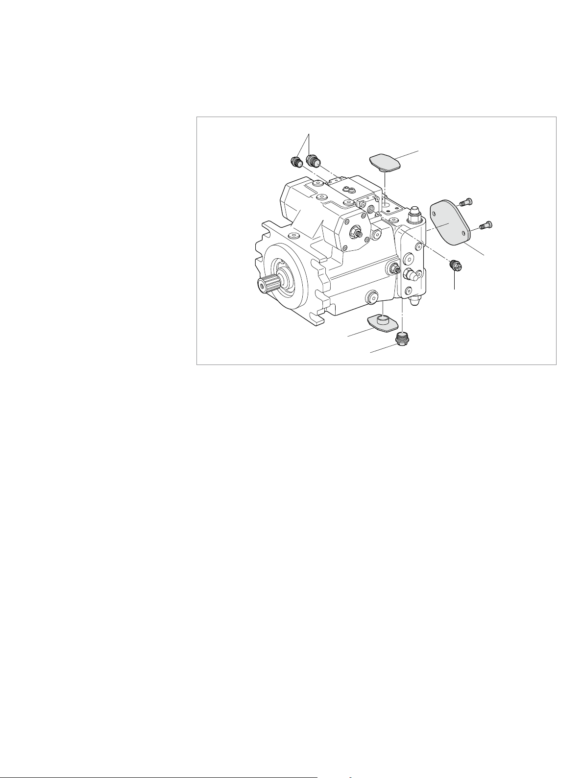
4 Scope of delivery
2
1
3
2
1
2
Fig. 1: Axial piston unit
The delivery includes the following:
• Axial piston unit as per order confirmation
The following parts are also assembled prior to delivery:
• Protective covers(1)
• Protective plug/threaded plug(2)
• For version with through drive, metallic protective cover and mounting bolts(3)
RE 92003-01-B/12.2015, A4VG Series 32, Bosch Rexroth AG
20/68 About this product
Closed circuit
5 About this product
5.1 Performance description
The axial piston variable pump generates, controls and regulates a hydraulic fluid
flow. It is designed for mobile applications such as construction machinery.
Refer to data sheet 92003 and the order confirmation for the technical data,
operating conditions and operating limits of the axial piston unit.
5.2 Product description
The A4VG is an axial piston variable pump with swashplate design for hydrostatic
drives in closed circuits. The flow is proportional to the drive speed and
displacement. The flow can be steplessly changed by controlling the cradle (12). For
axial piston units with swashplate design, the pistons are arranged axially relative to
the drive shaft.
In the closed circuit, the hydraulic fluid flows from the hydraulic pump to the
consumer, e.g. hydraulic motor and from there directly back to the hydraulic pump.
There is a high-pressure side and a low-pressure side which alternate depending on
which side is under load.
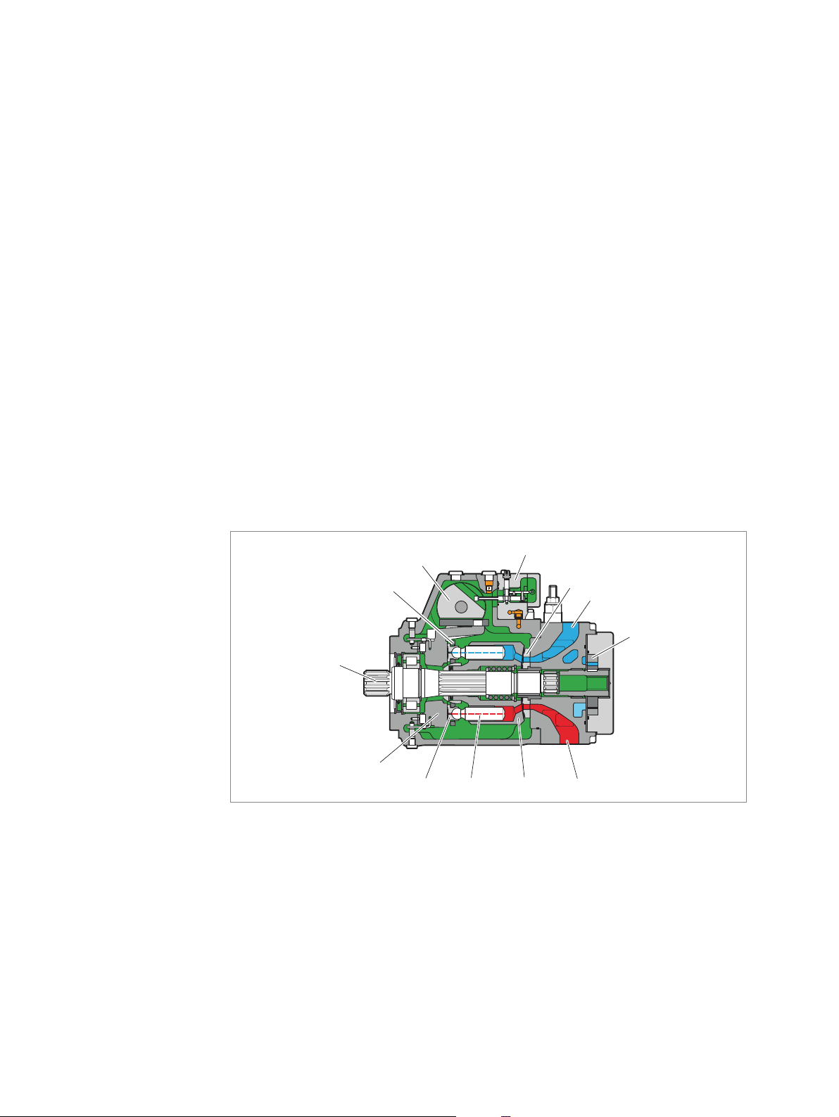
5.2.1 Layout of the axial piston unit
3
2
1
12
Fig. 2: Layout of the A4VG Series 32
1 Drive shaft
2 Retainer plate
3 Stroking piston
4 Control unit
(using the EP as
an example here)
5 Control plate
(distributor plate)
6 Low-pressure side
7 Boost pump
8 High-pressure side
4
5
6
7
891011
9 Cylinder
10 Piston
11 Slipper pad
12 Cradle
Bosch Rexroth AG, A4VG Series 32, RE 92003-01-B/12.2015

About this product 21/68
5.2.2 Functional description
Pump function
Torque and rotational speed are applied to the drive shaft(1) by a drive motor. The
drive shaft is connected by splines to the cylinder(9) to set this in motion. With every
revolution, the pistons(10) execute a stroke in the cylinder bores, the size of which
depends on the pitch of the cradle(12). The slipper pads (11) are held on with the
pistons and guided along the glide surface of the cradle by the retaining plate (2).
The pitch of the swashplate during a rotation causes each piston to move over the
bottom and top dead centers and back to its initial position.
Here, hydraulic fluid is fed in and drained out through the two control slots in the
control plate(5) according to the stroke displacement. On the high-pressure side(8)
the hydraulic fluid is pushed out of the cylinder chamber and into the hydraulic
system by the pistons. On the low-pressure side, (6) hydraulic fluid simultaneously
flows into the enlarging piston chamber – in a closed circuit this is supported by the
return and boost pressures.
Pressure cut-off
The working pressure is limited by the pressure cut-off.
The pressure cut-off corresponds to a pressure control which reduces the pump
capacity once the set specified pressure command value is reached so that the set
pressure is maintained but not exceeded.
High-pressure safeguarding
The two high-pressure relief valves protect the hydrostatic transmission (pump and
motor) from overloading. They limit the maximum pressure in the respective highpressure line and serve simultaneously as boost valves. High-pressure relief valves
are not working valves and are only suitable for pressure peaks or high rates of
pressure change.
Version with boost pump
The boost pump (7) continuously supplies a sufficient volume of fluid (boost volume)
from a small reservoir to the low-pressure side of the closed circuit via a check valve
to replenish the internal leakage of the variable pump and consumer. The boost
pump is an internal gear pump which is driven directly via the drive shaft.
Version without boost pump
(external feed in supply)
In order to replenish the internal leakage in the variable pump and consumers,
must be connected to an external source of boost pressure. The boost
portF
a
pressure relief valve is integrated.
Stroking chamber bypass
(optional)
The optional stroking chamber bypass connects both of the stroking chambers to
enable pressure equalization. The springs in the stroking chambers move the
stroking piston (3) towards the central position (neutral position). The reset function
is influenced by the current working pressure and the speed.
A bypass circuit for the two stroking chambers does not ensure that the pump goes
to the central position (neutral position).
▶ Use an appropriate emergency-off device to ensure that the drive can be brought
to a safe position at any time. The machine or system manufacturer is responsible
for the installation of a proper emergency-off device.
Sequence valve
(optional)
The optional sequence valve interrupts the active control pressure. The springs in
the stroking chambers move the stroking piston (3) towards the central position
(neutral position). The reset function is influenced by the current working pressure
and the speed.
Switching off the control pressure does not ensure that the pump goes to the central
position (neutral position).
▶ Use an appropriate emergency-off device to ensure that the drive can be brought
to a safe position at any time. The machine or system manufacturer is responsible
for the installation of a proper emergency-off device.
RE 92003-01-B/12.2015, A4VG Series 32, Bosch Rexroth AG
 Loading...