

Page 1
GOOD.BEETER>B OSCH
Instal lation / Operating Instructions
10P
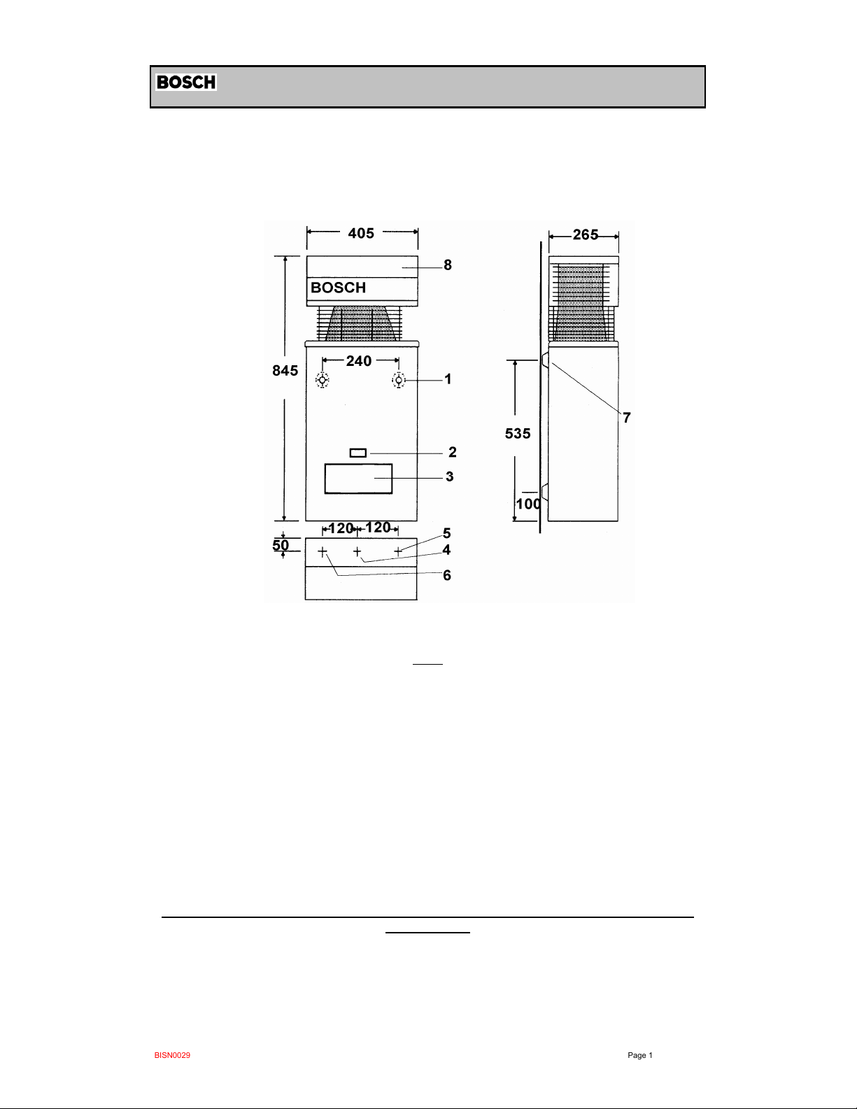
Continuous Flow Gas Water Heater
1 Main Cover 5 Cold Water Inlet
2 Inspection Window 6 Hot Water Supply
3 Access Panel 7 Mounting Point
4 Gas Inlet 8 Horizontal Flue
This appliance must be installed in accordance with the manufacturer’s installation instructions
AG 601, NZ 5261, AS3500.4.2
and all Local W ater,Building and Gas fitting regulations
Fig. 1
,
To be installed and serviced only by an authorised person
This applianc e is not suitable for use as a pool heater
The “authorised installing person” is responsible for :
1. Correct commissioning of this appliance.
2. Ensure unit performs to the specifications stated on the rating label.
3.. Demonstrate operation of unit to customer before leaving.
4. Hand these instructions to customer.
Failure to install this appliance in accordance with these installation instructions may
void warranty
In t he interest of co nt inued product im provement, Bosch reserves the right to alt er
these specificat ions without notice
BISN0029 Page 1
25/10/2011
Page 2
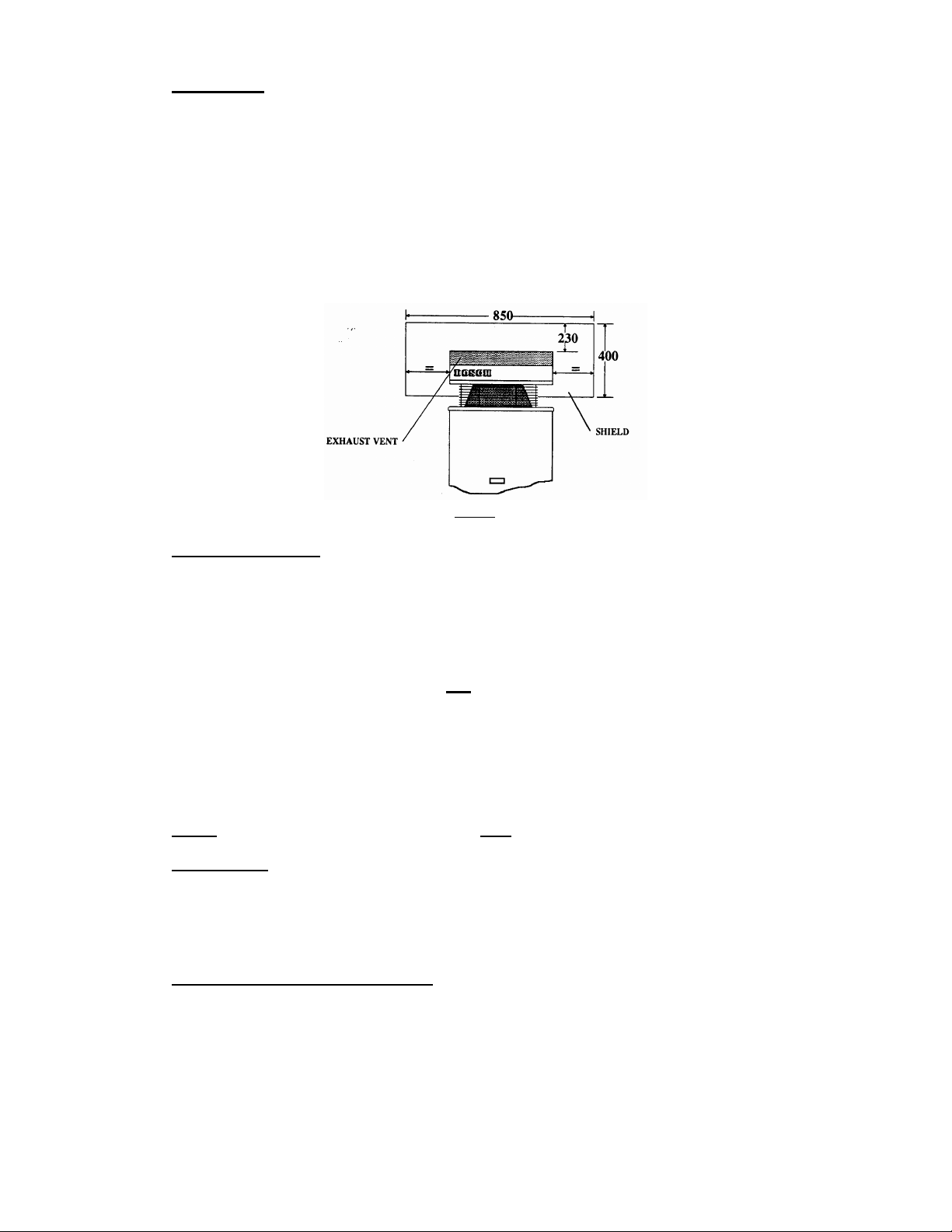
Installation
Install only on an external wall, as close as possible to the most frequently used hot
tap. Use a heat shield (accessory item part number 9 708 061 400) if the unit is to be installed
on a combustible surface. Allow minimum air gap of 10 mm between the flue and the heat
shield, (refer figure 2).
Ensure that the flue terminal is clear of any combustible material, and avoid
installation in a marine environment.
Install the appliance such that the base of the appliance is not more than 1.3 metres
and not less than 0.5 meters from the ground, and allow for easy access to service heater.
Secure heater to wall using two 10g X 5/16 hex head wood screws
Locate head of screw in the key hole of the top mounting bracket.
(Ramset 610041 or similar)
.
Fig. 2
Pip e Connections
Hot and Cold water ½" male
Natural gas ¾" female
L.P. gas ½" male
A gas cock must be installed in the gas supply line with provision to disconnect the
appliance. Install gate valve or full flow ball valve (fixed mechanism type) in cold water supply.
Refer to Fig. 1 for locations
A non return val ve m ust not be fitted. Example duo valve
We recommend that all hot water pipes be lagged if the runs are long or exposed, and
water-proof lagging should be used on all external hot water pipes. If the water supply
pressure exceeds 80% of the specified maximum, install a pressure limiting valve.
If installing a pressure limiting valve fit a cold expansion valve between the limiting valve and
the appliance. PLV = 500kPa Cold expansion = 700kPa
Refer to AG 601 and AS3500.1 for the relevant pipe size.
NOTE:
Service calls for incorrect pipe sizing will NOT be covered under warranty.
Water Filter
If sludge or foreign matter is or may be present in the water supply, it is recommended
that a suitable filter be incorporated in the water supply line to the heater. All pipes should be
well flushed before connection is made.
A water filter/strainer is installed in the inlet of the brass water valve inside the appliance.
Water Temperature Adjustment
Located inside the water heater, immediately below the gas controls, is a water
temperature selector knob.
To increase the water temperature ( decrease water flow ) turn the knob clockwise. To reduce
water temperature ( increase water flow ) turn the knob anti clockwise.
BISN0029 Page 2
25/10/2011
Page 3
Characteristic Data
Pilot orifice diameter (mm) NG 0.30
Burner injector diameter (mm) NG 1.20
Burner pressure ( kPa ) NG 0.87
Water flow selector at left hand stop.
Maximum water flow 10 litres / minute
Temperature rise 25°C
Minimum inlet pressure NG 90 kPa
Water flow selector at right hand stop
Minimum water flow 4.5 litres / minute
Temperature rise 55°C
Minimum inlet pressure NG 30 kPa
LPG 0.19
TG 0.56
TLP 0.56
LPG 0.75
TG 2.15
TLP 2.15
LPG 2. 0
TG 0.40
TLP 0.40
LP 55 kPa
LP 10 kPa
4
( 9.0 metres W.G.)
( 5.5 metres W.G.)
( 3 metres W.G. )
( 1 metre W.G. )
Refer to rating label located on the bottom right hand corner of the back panel for additional
data.
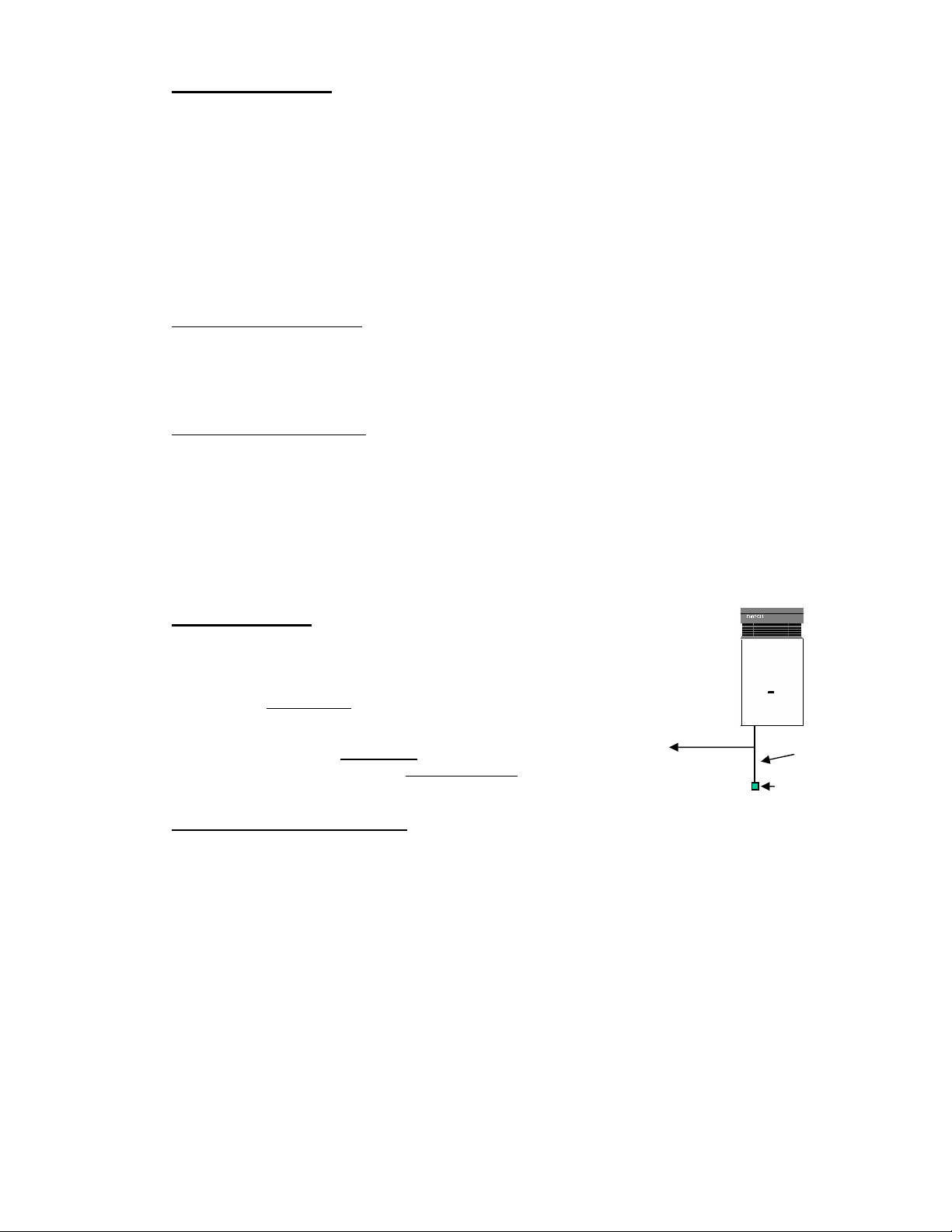
Freezing
Weather
In areas where the atmospheric temperature may drop below 0°C,
the heater must be drained to prevent damage by expansion of freezing
water. For appliances installed in locations where the temperature falls
below 0° C for brief periods , the installation of an EXOGEL expansion
valve, (part number H 707 060 151), will minimise the possibility of damage
to the appliance.
Hot Water
This water heater MUST NOT be installed in areas where the
temperature remains below 0°C for extended periods.
Conversion and Spare Parts
For spare parts or conversion of the heater to operate on a different gas that for which it was
originally manufactured, please contact your local gas authority, authorised service agent or
the manufacturer
1 Metre
minimum
Exogel
BISN0029 Page 3
25/10/2011
Page 4

Operating instruc tions
Open all hot water taps to expel any air prior to lighting
Remove front cover by loosening the two screws at the lower rear corners of the cabinet.
Check that gas and water valves are open, operate as indicated in Fig. 3
Refit front cover and tighten screws
Fig. 3
Warning - If the pilot light is extinguished, wait 5 minutes before attempting to
relight the appliance. If the appliance does not operate, burns with yellow
flame, leaks water or a gas smell is evident, turn off and contact the local gas
authority, the manufacturer or an authorised service person.
When attempting to light the appliance ensure that all hot water taps are
turned off
BISN0029 Page 4
.
25/10/2011
Page 5

Commissioning
Gas Inlet Pressure Adjustment
With the gas supply turned off, remove sealing screw from inlet pressure test point located on
the right hand side of the gas section refer Fig. 4 pos.A, attach manometer. Turn on gas and
light heater. Open hot water tap fully and adjust gas pressure regulator to 1.13kPa for NG
or 2.60kPa for LPG. Turn off gas and water, remove manometer, replace sealing screw
and test for escape.
Gas Burner Pressure Adjustment
Turn off gas supply, loosen captive screw in burner pressure test point, left hand side of
burner manifold refer Fig.5 Pos A, attach manometer turn on hot water tap fully and check
pressure.
Adjust pressure by turning the knurled wheel clockwise to increase gas pressure, anti
clockwise to decrease. refer Fig 4 Pos.E
Fig. 4
Fig 5
Maintenance
We recommend that the appliance be inspected and cleaned by an authorised person
periodically, depending upon the frequency and duration of its operation, but never less than
once a year.
BISN0029 Page 5
25/10/2011
Page 6

Fault Finding.
Problem Possible Cause Solution
Appliance does not light No gas supply
Blocked pilot
Pilot lights but no main burner Split/Distorted diaphragm Replace
Smell of gas Luminous flame
Loose gas connection
Yellow flame Burner venturi blocked Clean with venturi brush
Water leak on top of water valve lid Damaged O ring
Connect to supply
Replace pilot injector
Clean burner
Locate leak with soap solution
Replace O ring, grease with
#
Unisilkon L641
8709918413
Excessive pressure
Check water isolating valve
(Must be gat e valve or sim ilar)
.
Drain appliance or fit Exogel
Low burner flame, water does not
heat up.
Frost damage
Low inlet gas pressure
Low burner pressure
expansion valve
#
H707060151
Check supply regulator and pipe
size
Check appliance regulator
Check thermostat bellows
Check thermostat insert
Low water temperature Water flow rate set too high
Low gas pressure
Thermostat faulty/out of
Set flow rate
Check pressure
Replace/Adjust thermostat
adjustment
Low water flow Low water pressure
Blocked water valve
Blocked heat exchanger
Blocked shower rose or tap
Check and adjust
Clean filter
Descale
Clean
aerator
Shower goes hot & cold Low flow water saver shower rose Replace with less restrictive rose.
Check operation at other tap
Operates only at high water flow Relief valve spring corroded
Installed incorrectly, cold supply to
Replace valve
Correct installation
hot outlet
Cuts off when operating Thermostat faulty/out of
Replace/Adjust thermostat
adjustment
Operates only with slow light valve
Wrong thermostat insert
Faulty diaphragm
Fit correct part
Replace
loose
Blocked passage between slow
Clean
light & venturi
Faulty slow light valve
BISN0029 Page 6
Clean/Replace
25/10/2011
Page 7

Water quality
All Bosch water heating appliances are constructed from high quality materials and
components and all are certified for compliance with relevant parts of Australian and New
Zealand gas, electrical and water standards.
Whilst Bosch water heaters are warranted against defects, the warranty is conditional upon
correct installation and use, in accordance with detailed instructions provided with the heater,
in the case of the water supplied to the heater, it is important that the water quality b e of
acceptable standard.
The water quality limits/parameters listed in water quality table are considered acceptable
and generally, Australian and New Zealand suburban water supplies fall within these
limits/parameters.
In areas of Australia and New Zealand where water may be supplied, either fully or partly,
from bores, artesian wells or similar, one or more of the important limits may well be
exceeded and the heater could, therefore, be at risk of failure.
Where uncertainty exists concerning water quality, intending appliance users should seek a
water analysis from the water supplying authority and in cases where it is established that the
water supply does not meet the quality requirements of the water quality table, the Bosch
warranty would not apply.
Water quali t y t able
Maxi mum levels
pH
6.5-9.0 +0.4 to -1.0
Table 8
BISN0029
Satur at ion
at 65 °C
Index( LSI)
(langelier )
Tot al
200
mg/ l
Har dness
250
mg/ l
Chl or ides
180
mg/ l1mg/ l
Sod ium
Ir on
25/10/2011
Page 7
Page 8

11
Warranty details
Robert Bosch (Australia) Pty Ltd
(Bosch) Manufacturer's Warranty
(Applicable for purchases from 1 January 2012)
All Bosch hot water units are carefully checked, tested and subject to stringent quality controls.
1. Warranty
Bosch offers, at its option, to repair or exchange this Bosch hot water unit or the relevant part listed in
clause 2 below at no charge, if it becomes faulty or defective in manufacture or materials during the
warranty period also stated in clause 2. This warranty is of fered in addition to any other rights or remedies
held by a consumer at law.
2. Warranty periods & coverage
(a) Domestic applications: 2 years (parts and labour)
(b) Heat exchangers used in domestic applications: 10 years (parts only)
(c) Commercial applications: 12 months (parts and labour)
(d) Heat exchangers used in Commercial applications 12 months (parts only)
All warranty periods commence on the date of purchase of the hot water unit by the end-user. However,
where the date of purchase by the end-user is more than 24 months after the date of manufacture, all
warranty periods will automatically commence 24 months after the date of manufacture.
3. Warranty exclusions
This warranty is VOID if any damage to or failure of the hot water unit is caused wholly or partly by:
(a) Faulty installation
(b) Neglect, misuse, accidental or non-accidental damage, failure to follow instructions
(c) Use of the unit for purposes other than which it was designed or approved
(d) Unauthorised repairs or alterations to the unit without Bosch's consent
(e) Use of unauthorised parts and accessories without Bosch's consent
(f) Use of non-potable water or bore water in the hot water unit (see product instructions for further details)
(g) Continued use after a fault becomes known or apparent.
This warranty DOES NOT include:
(a) Costs of consumables or accessories
(b) Wear and tear, normal or scheduled maintenance
(c) To the extent permitted by law, any damage to property, personal injury, direct or indirect loss,
consequential losses or other expenses
(d) Changes in the condition or operational qualities of the hot water unit due to incorrect storage or
mounting or due to climatic, environmental or other influences.
NOTE: Any service call costs incurred by the owner or user of the hot water unit for any matter not covered
by the terms of this warranty will not be reimbursed by Bosch, even if those costs are incurred during the
warranty period. If the hot water unit is located outside the usual operating area of a Bosch service agent,
the agent's travel, freight or similar costs are not covered by this warranty and must be paid by the owner or
user of the hot water unit.
4. Warranty conditions
(a) Proof of purchase may be required.
(b) The hot water unit must be installed by an authorised and licensed installer.
(c) Proof may be required of the date of installation and correct commissioning of the hot water unit has
BISN0029 Page 8
25/10/2011
6 720 6 08 9 92 ( 2011/ 12)
Page 9

been carried out to Bosch's satisfaction (such as a certificate of compliance).
(d) Repair or replacement of the hot water unit or any parts under this warranty does not lengthen or
renew the warranty period.
(e) This warranty is not transferable and is only offered to the original purchaser of the hot water unit.
(f) No employee or agent of Bosch is authorised to amend the terms of this warranty.
(g) This warranty only applies to Bosch hot water units purchased from an authorised reseller and
installed in Australia or New Zealand.
(h) To the extent that any condition or warranty implied by law is excludable, such condition or warranty
is excluded.
5. How to lodge a warranty claim and warranty procedure
Warranty claims must be made with the Bosch Customer Contact Centre
(a)
(Australia: ph 1300 307 037; New Zealand: ph 0800 543 352). Please be ready to provide the model and
serial numbers, date of installation, purchase details and a full description of the problem. Warranty claims
must be made before the end of the warranty period.
(b) All warranty service calls must conducted by an authorised Bosch service agent.
Invoices for attendance and repair of a hot water unit by third parties not authorised by Bosch will not
(c)
be accepted for payment by Bosch.
6. Privacy Act 1988 (Cth)
A customer's personal information collected during warranty claims may be used for the provision of
customer support, for t he provision of information about products and services and for other marketing
activities undertaken by Bosch and its Bosch Service Agents who are authorised to carry out warranty
repairs on behalf of Bosch (Purpose). Bosch is committed to protecting the privacy of its customers'
personal information. It will act in compliance with the National Privacy Principles and Privacy Act 1988
(Cth). Bosch will not forward customers' personal information to third parties other than for the Purpose. A
customer can object at any time to the use of their personal information for the purpose. Bosch will cease to
use a customer's personal information accordingly if an objection is made.
7. Bosch contact details
If you have any questions about this warranty or to lodge a warranty claim, please contact:
Robert Bosch (Australia) Pty Ltd
1555 Centre Road, Clayton, Victoria 3168
Tel: Australia: 1300 307 037
Tel: New Zealand: 0800 543 352
IMPORTANT NOTE FOR AUSTRALIAN CONSUMERS
Our goods come with guarantees that cannot be excluded under the Australian Consumer Law. You are
entitled to a replacement or refund for a major failure and for compensation for any other reasonably
foreseeable loss or damage. You are also entitled to have the goods repaired or replaced if the goods fail to
be of acceptable quality and the failure does not amount to a major failure.
BISN0029
6 720 608 992 ( 2011/ 12)
25/10/2011
Page 9
 Loading...