

Bosch 940 ESO Installation Manual
940 ESO
For Outdoor Installations Only
Temperature Modulated with Electronic Ignition
Suitable for heating potable water and space heating
(Intended for variable flow applications)
6720644956-00.1V
940 ESO - Natural Gas
940 ESO - Liquefied Petroleum (LP) Gas
6 720 644 956 (2010/09) US
Warning: If the information in this manual is not
followed exactly, a fire or explosion may result
causing property damage, personal injury or death.
Do not store or use gasoline or other flammable
vapors and liquids in the vicinity of this or any other
appliance.
Improper installation, adjustment, alteration,
service or maintenance can cause injury or
property damage. Refer to this manual. For
assistance or additional information consult a
qualified installer, service agency or the gas
supplier.
In the Commonwealth of Massachusetts this
product must be installed by a licensed plumber or
gas fitter.
Upon completion of the installation, these
instructions should be handed to the user of the
appliance for future reference.
What to do if you smell gas
• Close gas valve. Open windows.
• Do not try to light any appliance.
• Do not touch any electrical switch; do not use any
phone in your building.
• Immediately call your gas supplier from a neighbor’s
phone. Follow the gas supplier’s instructions.
• If you cannot reach your gas supplier, call the fire
department.
• Installation and service must be performed by a
qualified installer, service agency or the gas supplier.
6 720 644 956
2
Index
Index
1 Warning 3
2 Appliance details 5
2.1 Features 5
2.2 Specifications (Technical data) 5
2.3 Unpacking the heater 6
2.4 General rules to follow for safe operation 7
2.5 Dimensions and Min. installation clearances 8
3 Installation requirements 9
3.1 Specialized tools 9
3.2 Introduction 9
3.3 Proper location for installing your heater 9
4 Installation using Outdoor Kit (BTOK) 10
4.1 Warnings 10
4.2 Installing outdoor vent cap on the appliance 10
4.3 Selecting heater location 12
4.4 Mounting instructions 13
5 Installation using the Recess
Box (7 736 500 043) 14
5.1 Heater placement and clearances 14
6 Installation instructions 17
6.1 Gas piping & connections 17
6.2 Water connections 20
6.3 Water quality 20
6.4 Domestic hot water recirculation 21
6.5 Space heating applications 22
6.6 Measuring gas pressure 24
7 Electrical connections 25
7.1 Electrical power supply 25
7.2 Position of the fuses in control unit 25
8 Operation instructions 26
8.1 Description of LCD display 26
8.2 For your safety read before operating
your water heater 27
8.3 Power 27
8.4 Temperature selection 27
8.5 Use of optional remote control accessory
(part no. TSTAT2) 28
8.6 Operation 28
8.7 Reset button 28
8.8 Fan speed 29
8.9 Program button 31
8.10 Locked condition 31
9 Maintenance and service 31
9.1 Annual maintenance 31
9.2 Winterizing for seasonal use 32
9.3 Mineral scale build-up 32
9.4 Adjusting CO2 33
9.5 Program values 35
9.6 Control board diagnostics 36
10 Troubleshooting 37
10.1 Introduction 37
10.2 Burner does not ignite when hot
water is turned ON 37
10.3 Water is too hot 37
10.4 Water is not hot enough 37
10.5 Low water flow/pressure 38
10.6 Hot water temperature fluctuates
or goes cold at tap 38
10.7 Noisy burner/heater during operation 38
11 Problem solving 39
11.1 Error code diagnostics 39
12 Electrical diagram 43
13 Sensor resistance charts 44
14 GWH 940 ESO Functional scheme 46
15 Interior components diagram
and parts list 47
15.1 Interior components 47
15.2 Components diagram 49
16 Protecting the environment 55
17 Limited Warranty 56
6 720 644 956
Warning
3
1 Warning
For your safety
Do not store or use gasoline or other flammable,
combustible or corrosive vapors and liquids in the
vicinity of this or any other appliance.
Warning: Carefully plan where you
install the heater. Correct installation
location and proper combustion air
supply air supply are very important. If a
gas appliance is not installed correctly,
fatal accidents can result, such as
carbon monoxide poisoning or fire.
Warning: Exhaust gas must be vented
to outside.
Warning: Field wiring connections and
electrical grounding must comply with
local codes, or in the absence of local
codes, with the latest edition of the
National Electric Code, ANSI/NFPA 70,
or in Canada, all electrical wiring must
comply with the local codes and the
Canadian Electrical Code, CSA C22.1
Part 1.
Warning: Shock hazard: line voltage is
present. Before servicing the water
heater, unplug power supply cord from
outlet. Failure to do so could result in
severe personal injury or death.
Warning: The heater must be
disconnected from the gas supply
piping system during any pressure
testing of that system at test pressures
equal to or more than 0.5 psig.
Warning: The appliance should be
located in an area where leakage of the
heater or connections will not result in
damage to the area adjacent to the
appliance. When such locations cannot
be avoided, it is recommended that a
suitable drain pan, adequately drained,
be installed under the appliance. The
pan must not restrict combustion air
flow.
Warning: The maximum inlet gas
pressure must not exceed the value
specified by the manufacturer and the
minimum value listed is for the purpose
of input adjustment.
Warning: If a water heater is installed in
a closed water supply system, such as
one having a backflow preventer in the
cold water supply line, means shall be
provided to control thermal expansion.
Contact the water supplier or local
plumbing inspector on how to control
this situation.
Warning: Keep appliance area clear
and free from combustible materials,
gasoline and other flammable vapors
and liquids.
Warning: Do not obstruct the flow of
combustion and ventilation air.
Warning: Precautions must be taken
prior to manually operating the relief
valve to avoid contact with hot water
coming out of the relief valve and to
prevent water damage.
Caution: Label all wires prior to
disconnection when servicing controls.
Wiring errors can result in improper and
dangerous operation.
Verify proper operation after servicing.
Warning: If a relief valve discharges
periodically, this may be due to thermal
expansion in a closed water supply
system. Contact the water supplier or
local plumbing inspector on how to
correct this situation. Do not plug the
relief valve.
Warning: If the water heater is used in
a space heating application, all piping
and components connected to the
water heater must be suitable for use
with potable water.
Warning: Toxic chemicals, such as
those used for boiler treatment, shall not
be introduced into the potable water
used for space heating.
6 720 644 956
4
Warning
FCC:
This device complies with Part 15 of the FCC rules.
Operation is subject to the following two conditions: (1)
This device may not cause harmful interference, and (2)
this device must accept any interference received,
including interference that may cause undesired operation.
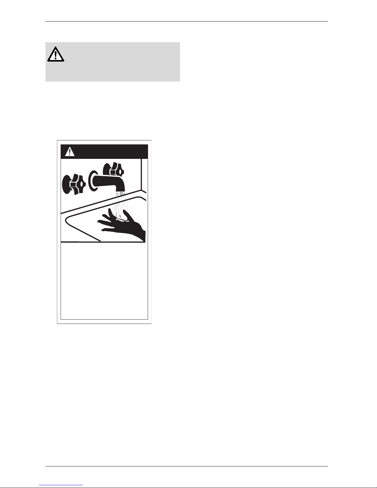
Fig. 1
Warning: A water heater which will be
used to supply potable water shall not
be connected to any heating system or
component(s) previously used with a
nonpotable water heating appliance.
HOT
BURN
D A N G E R
Watertemperatureover125°Fcan
causesevereburnsinstantlyor
deathfromscalds.
Children,disabledandelderlyare
athighestriskofbeingscalded.
Seeinstructionmanualbefore
settingtemperatureatwater
heater.
Feelwaterbeforebathingor
showering.
6720608643-16.1AL

6 720 644 956
Appliance details
5
2 Appliance details
2.1 Features
Parts
• Key Pad interface control
• High power pre-mix compact burner with low NOx
emissions
• Modulating Gas Valve with constant gas:air ratio
control
• Modulating water valve for improved comfort and
temperature control.
High quality materials for long working life
• Copper heat exchanger
• High efficiency Ceramat Burner
• Compact space saver: mounts on a wall with a
supplied bracket.
Features
• Real-time diagnostics for troubleshooting/
informational purposes
• LCD Display with backlight
• On/Off and Temperature control switches
• Reset button
• Program button (Selectable temperature default)
• Failure codes for easy diagnostics and repair
• Easily removable one-piece cover
• Built in freeze prevention1).
Accessories (Bosch part #)
• Optional wireless remote control accessory to
operate with the appliance (TSTAT2)
• Cascading kit (7709003962)
• External water filter (8703305356)
• Gas conversion kit (8719002176)
• Pipe Cover (PTPCES)
• Recess box (7736500043)
• Pressure relief valve (FWL-2).
2.2 Specifications (Technical data)
Approved in US/Canada
Capacity
Maximum flow rate: 7.15 GPM (27 l/min) at a 45°F
(25°C) rise.
Maximum output
160,500 Btu/h (47.0 kW)
Maximum input
199,000 Btu/h (58.3 kW)
Efficiency in %
Thermal efficiency > 82%
Min. Input
19,900 Btu/h (5.8 kW)
Temperature Control
Selection range: 100°F (38°C) - 140°F (60°C)
Default temperature: 122°F (50°C)
Stability: +/- 2°F (+/- 1°C)
Gas Requirement
Gas connection (inches) - ¾”
Inlet gas pressure under operation (with a high hot
water flow rate)*
• Propane: 8” - 13” water column
• Natural Gas: 3.5” - 10.5” water column.
* To measure gas pressure, see Measuring Gas
Pressure, chapter 6.6, page 24.
Water
• Hot water connection (inches) - ¾”
• Cold water connection (inches) - ¾”
• Water valve material: Polymer (PPS) (Polypropylene
Sulfid)
• Minimum water flow: 0.5 gallon/minute (1,9 l/m).
Note: Activation varies with inlet water temperatures
from 0.5 - 1.6 gallon/minute (1.9 - 6.1 l/m).
• Minimum recommended water pressure: 30 PSI
(2.07 bar).
• Minimum well pressure 40 psi, see page 20.
• Connections:
– Bottom of heater
Combustion
• NOx ≤ 40 Ng/J
(Nanograms of NOx (calculated as NO2) per
Joule of heat output).
• CO ≤ 250 ppm (measured)
• CO
2
level set from factory, see chapter 9.4, page 33.
1) The freeze prevention kit is designed to provide
protection for the water heater down to approximately
5°F for short term conditions only. It will not protect the
appliance in areas where the temperature is routinely
expected to be below freezing.
- The freeze prevention kit will not protect plumbing
outside the appliance from freezing. Precautions should
be taken.
i
BOSCH is constantly improving its
products, therefore specifications are
subject to change without prior notice.
6 720 644 956
6
Appliance details
Dimensions
• Depth (in): 11¼” (286 mm)
• Width (in): 17
7
/
8
” (452 mm)
• Height (in): 30½” (775 mm)
• Weight: 67 pounds (30.5 kg).
Gas types
Natural Gas.
LP Gas.
Voltage
120 V AC (60 Hz) nominal
Amperage
Idle - 40 mA
Operation - ≤ 2.5 A
Noise
45 - 65 db (A)
Safety devices
• Flame failure device (ionization flame rod sensor)
• Over heat prevention (temperature limiter)
• Inlet temperature sensor
• Outlet temperature sensor
• Back flow temperature sensor.
Water protection
IP X4 (protection against water drops)
2.3 Unpacking the heater
In order for proper installation, this water heater
must be installed with the outdoor kit (BTOK)
accessory.
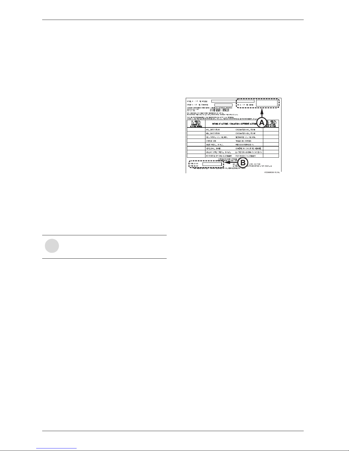
Before installing the unit, be certain you have the
correct heater for your type of Gas: Propane or
Natural Gas. Identification labels are found on
the shipping box, and on the rating plate which is
located on the right side panel of the cover.
Fig. 2 Rating plate
A Serial number
B Type of gas
The box includes:
• 940 ESO
• Bracket for wall hanging the heater
• Installation manual (manual can be downloaded at
www.boschpro.com)
• Product registration card
• Energy Guide label (in the front cover).
Please complete and return the enclosed product
registration card.
The 940 ESO is not approved or designed for:
• Manufactured (mobile) homes, boats or any
mobile installation. (Modular homes are
acceptable for installation).
• Use above 8000 ft A.S.L. altitude (see page 29).
• Outdoor installation without installation of
Outdoor kit (BTOK) or Recess Box (7 736 500
043).
• Applications where inlet water temperature is
higher than 140ºF (60°C). A 3-way valve or
mixing valve must be installed before the
appliance if inlet water temperature exceeds
this limit.
i
If appliance is installed at elevations above
2000ft, refer to Section 8.8.1 Fan speed
adjustment.
6 720 644 956
Appliance details
7
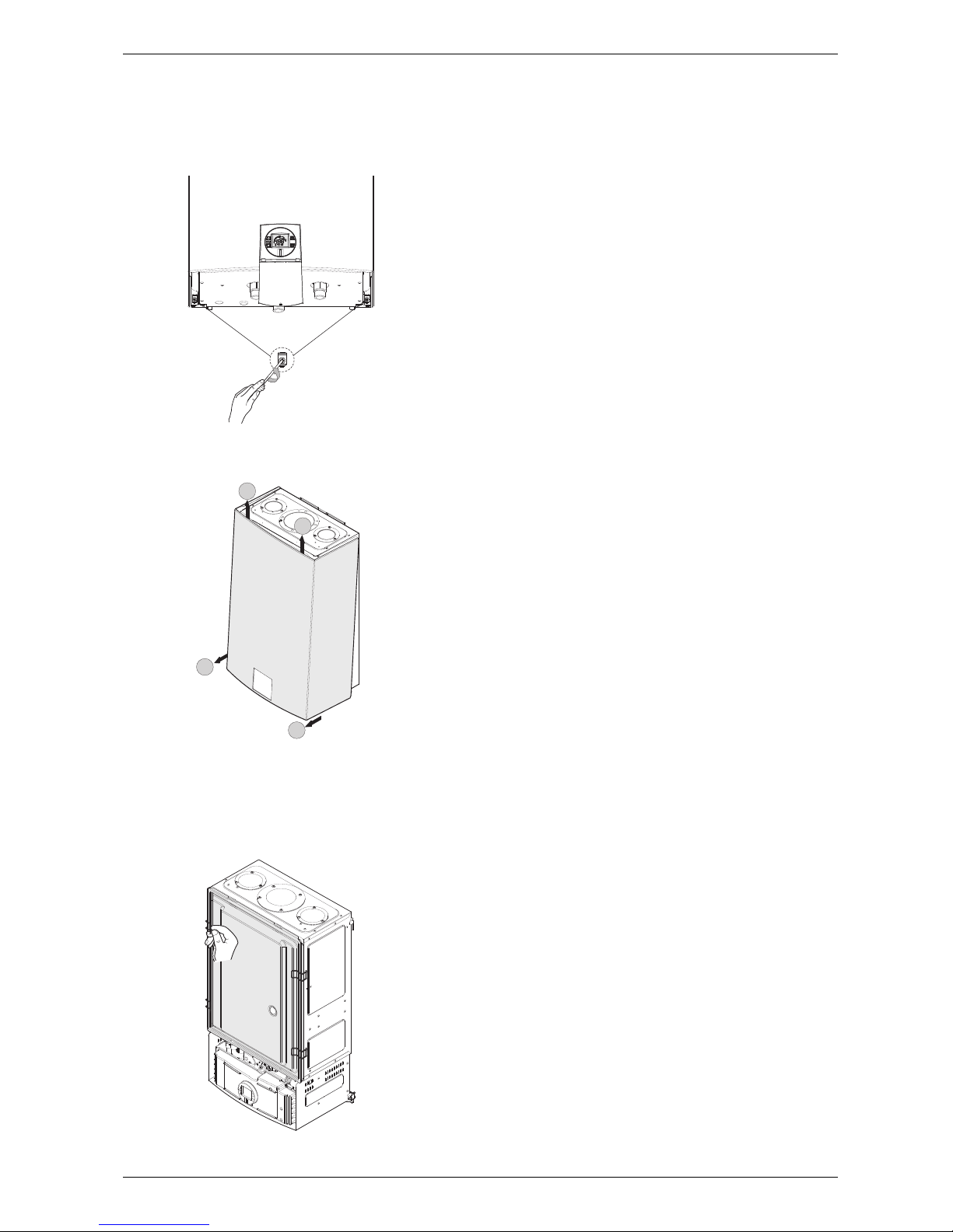
To remove front cover
B Loosen the two Phillips head screws located on
bottom rear of cover (see Fig. 3).
Fig. 3 Loosen the two screws
B Lift front cover panel upward and remove.
Fig. 4 Remove the front cover
To remove combustion cover (service only)
B Open the four clips and remove the combustion
cover see Fig. 5.
Fig. 5 Remove the combustion cover
2.4 General rules to follow for safe
operation
B
1. You must follow these instructions when you install
your heater. In the United States: The installation must
conform with local codes or, in the absence of local
codes, the National Fuel Gas Code ANSI Z223.1/
NFPA 54.
In Canada: The Installation must conform with CGA
B149.(1,2) INSTALLATION CODES and /or local
installation codes.
B 2. Carefully plan where you install the heater. If not
installed correctly, fatal accidents can occur, such as
carbon monoxide poisoning or fire.
B 3. The water heater must be installed outdoors using
the outdoor kit and/or recess box accessory.
B 4. You must vent your heater so that the exhaust
gases discharge to the outdoors.
B 5. The appliance and its gas connection must be leak
tested before placing the appliance in operation.
The appliance must be isolated from the gas supply
piping system by closing its individual manual gas
shutoff valve (not supplied with heater) during any
pressure testing at pressures in excess of ½ Psig (3.5
kPa).
B 6. Keep water heater area clear and free from
combustibles and flammable liquids. Do not locate
the heater over any material which might burn.
B 7. Correct gas pressure is critical for the proper
operation of this heater. Gas piping must be sized to
provide the required pressure at the maximum output
of the heater, while all the other gas appliances are in
operation. Check with your local gas supplier, and
see the section on connecting the gas supply, see
chapter 6.1
.
B 8. Should overheating occur or the gas supply fail to
shut off, turn off the gas supply at the manual gas shut
off valve, on the gas line. Note: manual gas shutoff
valve is not supplied with the heater but must be field
installed.
B 9. Do not use this appliance if any part has been
underwater. Immediately call a qualified service
technician to inspect the appliance and to replace any
part of the control system and any gas control which
has been underwater.
B
10. Failure to install heater correctly may lead to
unsafe operation and void the warranty.
6720644956-02.1V
1
2
1
6720644956-13.1V
2
6720644956-14.1V
6 720 644 956
8
Appliance details
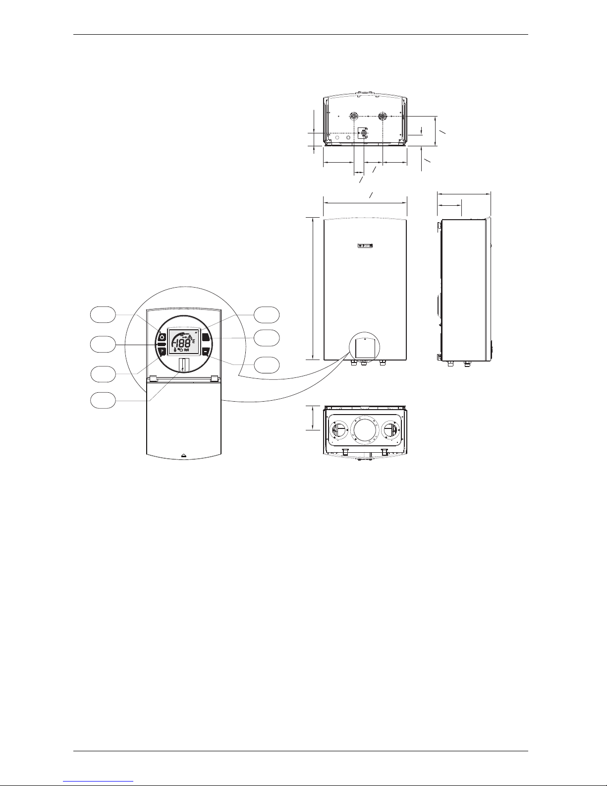
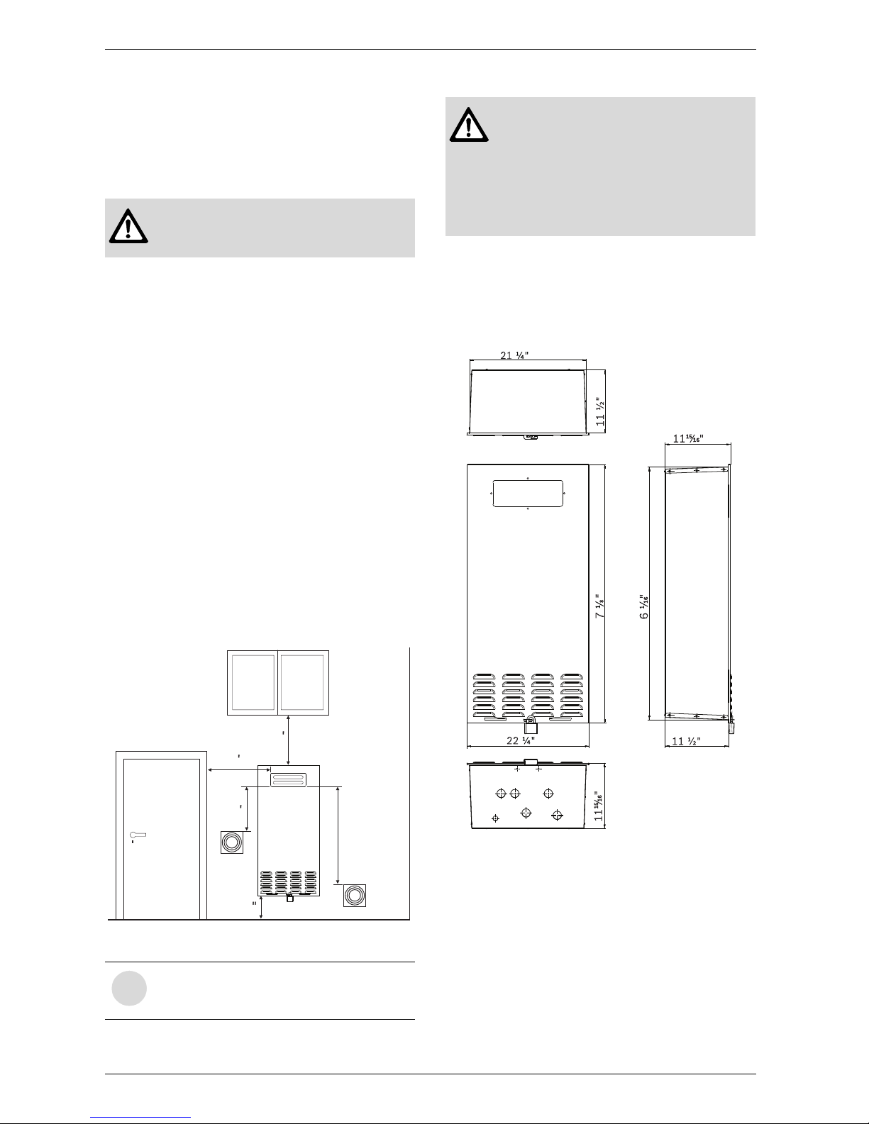
2.5 Dimensions and Minimum installation clearances
Fig. 6 Dimensions
1 On/Off button
2 Reset button
3 Program key
4 Power ON or stand-by LED
5 LCD display
6 Up button
7 Down button
6720644956-01.1V
2
3
1
6
5
7
4
5 ¼"
30 ½"
17 "
7
8
5 ¼"
11 ¼"
2 ¾"
6 ½"
2 "
16
5
5 ¼"
2 "
16
4 "
1
16
6 "
5
16
1
16
5
16
res et
P
+
6 720 644 956
Installation requirements
9
3 Installation requirements
3.1 Specialized tools
The following specialized tools may be required for
installation:
• Manometer
• Multi-meter
• Combustion Gas Analyzer.
3.2 Introduction
Please follow these instructions. Failure to follow
instructions may result in:
B Damage or injury.
B Improper operation.
B Loss of warranty.
If you are unable to perform the tasks required to install
this heater properly, please contact a locally licensed
plumber or gas technician.
3.3 Proper location for installing your
heater
Carefully select the location of the water heater. For
your safety and for proper heater operation, follow the
guidelines below:
B 1. Locate the heater where gas and plumbing
connections are feasible and convenient.
B 2. The hot water lines should be kept short and
insulated to save energy. Centrally locating the water
heater is recommended to keep hot water
distribution times even throughout the structure.
Warning: The water in this water
heater is cold and always remains cold
except for the times the burner is on. In
the event of power outage in
conjunction with freezing temperatures,
it is recommended that the heater be
drained.
See chapter 9.2, page 32 “Winterizing”
for draining instructions.
Warning: Flammable materials,
gasoline, pressurized containers, or any
other items or articles that are potential
fire hazards must NOT be placed on or
adjacent to the heater. The appliance
area must be kept free of all
combustible materials, gasoline and
other flammable vapors and liquids.
6 720 644 956
10
Installation using Outdoor Kit (BTOK)
4 Installation using Outdoor Kit (BTOK)
4.1 Warnings
Outdoor kit (BTOK) includes:
• Supports (2) with screws
• Sealing gasket
• Control panel shield
• Outdoor vent cap.
4.2 Installing outdoor vent cap on the
appliance
Replace the control panel shield
B Loosen the two Phillips head screws located on
bottom rear of cover (see Fig. 3).
Fig. 7 Loosen the two screws
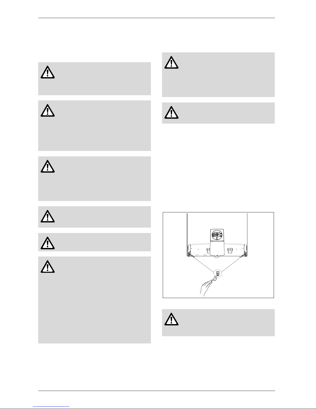
B 1. Attach the supports (A) to the appliance by fasten-
ing with the four provided screws, as shown in Fig. 8.
Danger: The top of the outdoor kit will
get very hot during operation. Keep
away from children. Install heater in a
location where the top of the kit cannot
be reached by small children.
Danger: Flue gas will be released
through the outdoor kit. Flue gas is very
hot and contains carbon monoxide. The
outdoor kit cannot be installed on a
water heater mounted indoors. To
prevent risk of fire and carbon monoxide
poisoning, maintain all clearances
indicated in these instructions.
Danger: Do not place or store any
combustible material within 5 feet of the
appliance. Maintain specified clearance
to combustibles on the wall where the
appliance is installed and any adjacent
walls or overhang. Observe all
clearances required in this manual.
Danger: Surface temperature of the kit
is less than 140°F, except highest top
surface which may reach 300°F.
Warning: Do not mount water heater
directly onto vinyl siding, see Fig. 14.
Danger: the freeze prevention kit on
the appliance is designed to provide
protection from temperatures down to
approximately 5°F for short term
conditions only. It will not protect the
appliance in areas where the
temperature is routinely expected
to be below freezing. The freeze
prevention kit will not protect plumbing
outside the appliance from freezing.
Precautions must be taken:
B Always drain the water heater if it will be
exposed to long term freezing conditions.
Danger: the water in this appliance is
cold and always remains cold except for
the times when the burner is on. In the
event of power outage in conjunction
with freezing temperatures, it is
recommended that the heater be
drained.
Warning: Damage to the appliance
from freezing is not covered under the
manufacturer's warranty.
Warning: The control panel shield
must always remain closed, except
when making adjustments, to prevent
damage to heater from weather.
6720644956-02.1V
6 720 644 956
Installation using Outdoor Kit (BTOK)
11
Fig. 8
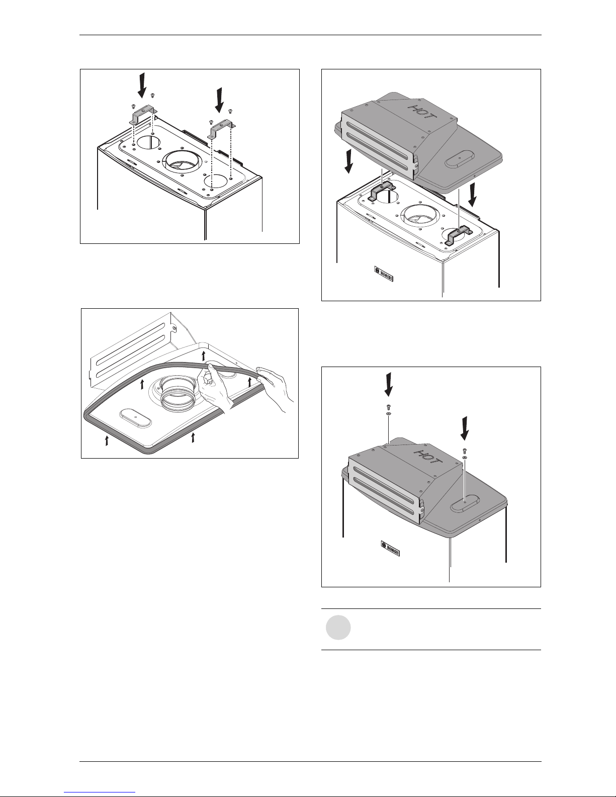
Before mounting the outdoor kit in the appliance:
B 3. Attach the gasket provided with the kit as shown
in Fig. 9.
Fig. 9
B Position the outdoor vent cap on the top of the
appliance, as shown in Fig. 10.
Fig. 10
B Attach the outdoor vent cap to the appliance by fas-
tening the two provided screws and washers, see
Fig. 11.
Fig. 11
A
6720644956-03.1V
A
6720645551-15.1V
i
NOTE: Once this kit is installed, the
outdoor vent cap will need to be removed
before removing the front cover.
6720645551-11.1V
6720645551-12.1V
6 720 644 956
12
Installation using Outdoor Kit (BTOK)
4.3
Selecting heater location
Before proceeding, read the water heater installation
manual. If the information in that manual is not followed
exactly, a fire, explosion or poisoning by carbon monoxide may result causing property damage, personal injury
or death.
B Choose an outside wall for the installation.
Installation on a wall protected by an overhang above
is recommended.
B Size the water and gas connections according to the
instructions in the water heater installation manual.
Use unions when connecting both water lines and
gas supply line to the heater.
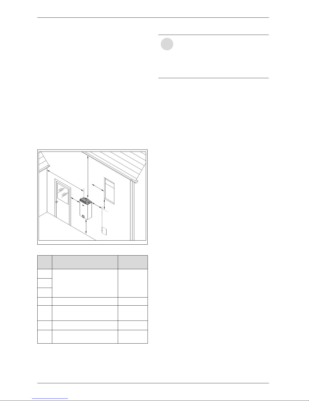
Minimum clearances
If the appliance is installed under an overhang, there
must be a 36” clearance from the top of the appliance
and the mounting area must be open in front and on the
sides of the appliance.
Fig. 12
Ref. Description
Min.
distances
A
Directly below or adjacent to
an opening; operable
windows, doors and any fresh
air openings
≥ 1 ft
B
C
D From any adjacent wall ≥ 1 ft
E
Below a gutter, sanitary
pipework, eaves or overhang
≥ 3 ft
F Above ground ≥ 1 ft
G
From a gas meter or gas
regulator
≥ 3 ft
Table 1 Clearances
6720645551-10.1V
D
A
B
G
E
C
F
i
Best practice note: The clearances in
Fig. 12 and table 1 are the minimum
allowed by the standard.
When possible consider maximizing the
clearances A, B, C, D and E to allow for
the effects of wind and frequently used
door and window openings.
6 720 644 956
Installation using Outdoor Kit (BTOK)
13
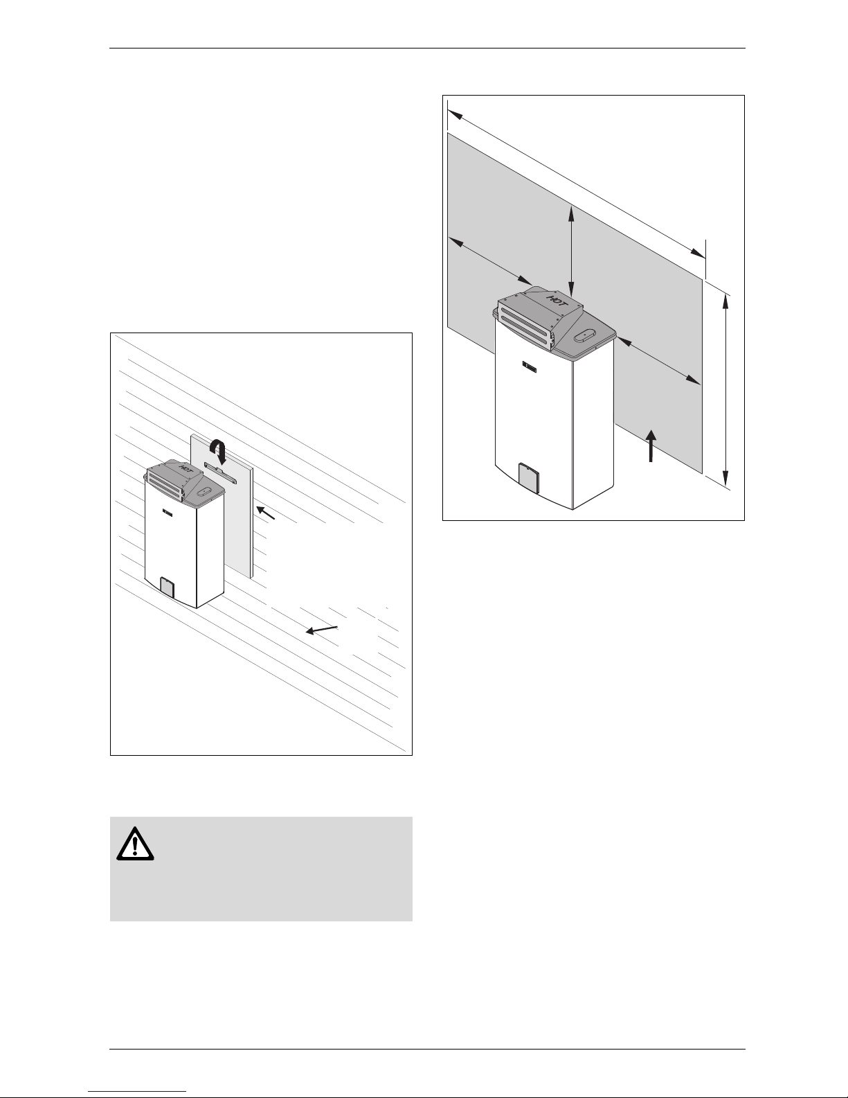
4.4
Mounting instructions
B The water heater is approved for installation directly
on an outside wall. Secure the wall mounting bracket
provided with the water heater to a wall surface. See
Fig. 13.
B The installation method of the mounting bracket will
depend on the type of mounting surface. Due to the
varieties of building siding or surfacing, the installer
must decide on how best to support and level the
heater on an outside wall. It is recommended that
horizontal or vertical support boards or plywood
sheathing (1/2” minimum) first be attached to the
wall surface. The heater must also be kept level on
the wall surface.
Fig. 13 Installation on wood siding
Fig. 14 Installation on vinyl siding
Warning: Do not mount heater directly
to vinyl siding. With vinyl siding, a 3½' x
4' area of the siding must first be
removed and then replaced with wood
or other non-plastic material. See
Fig. 14.
Plywood (½" minimum)
or other solid wood
material(s) to anchor the
wall support bracket and
keep the heater level
against wall surface
Wood
siding
6 7 2 0 6 0 8 5 4 7 - 0 8 . 1 J S
4’
Vinylsiding
Woodor
non-plastic
material
3½’
³12”
³12”
³12”
6 720 644 956
14
Installation using the Recess Box (7 736 500 043)
5 Installation using the Recess
Box (7 736 500 043)
5.1 Heater placement and clearances
The water heater is approved for installation on a
combustible wall (see chapter 4.4 Mounting
installation) provided the floor covering below
the heater is noncombustible. For installations in an
alcove or closet, maintain the minimum clearances to
combustible and non-combustible materials. See
chapter 2.5, page 8.
Do not install the Recess box:
• Under a deck or patio.
• Side of the building with prevailing winter winds.
• Close to plants or trees.
• In areas where people or animals can accidentally
touch louvered exhaust openings.
• Maintain a clean area in front of the appliance of 4
feet (1,2m).
The Recess box should be installed so the discharge
vent maintains the minimum allowable clearances as
required by the local authority. Where no local requirement exists, maintain the following minimum suggested
clearances from builing openings as shown in Fig. 15.
Fig. 15 Discharge vent clearances
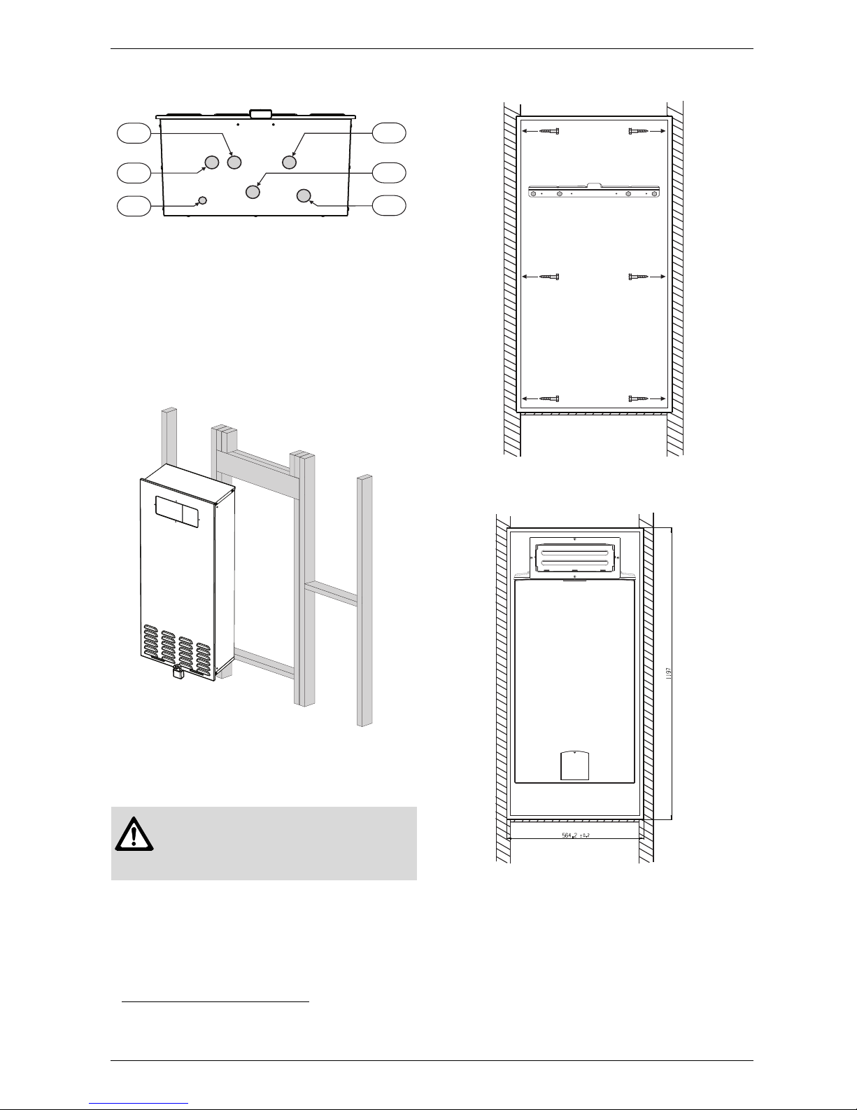
5.1.1 Wall cavity
Dimensions of Recess Box
When building the wall cavity for the recess box, make
preparations for the water and gas lines and electrical
wires as well.
Fig. 16 Recess box dimensions in inches (mm)
Warning: The water heater with recess
box accessory is intended for an outdoor installation only.
i
Top, front, and side clearances noted on
the front cover of the water heater are not
applicable when installed in a Recess box.
3
1
1
1
6720644960-01.1V
12
Warning: Improper installation!
This recess box has been designed to be
mounted in a wall cavity with exhaust vent
discharging to the outdoors. Do not install
the recess box in another configuration.
Damages resulting from an improper installation will not be covered by Bosch limited
warranty.
6720644960-02.1V
(540)
(303)
(293)
(1197)
(1170)
(564)
(293)
4
4
(303)
6 720 644 956
Installation using the Recess Box (7 736 500 043)
15
Fig. 17 Recess box plumbing/electrical openings
1 Hot water opening
2 Pressure relief valve opening
3 Electrical opening
4 Cold water opening
5 Gas opening
6 Condensing opening
1)
B Secure the wall mounting bracket provided with the
heater to the wall surface. The heater must be kept
level on the wall surface, see Fig. 19, page 15.
Fig. 18 Support boards
B Hang water heater on wall mounting bracket. Ensure
heater is level.
Fig. 19 Leveling the mounting bracket and screwing
the recess box on the studs
Fig. 20 Mounting the heater inside recess box
1) Not used with this appliance.
Caution: Ensure the outdoor kit
(BTOK) accessory has been installed on the water heater prior to
operating -see section 4.2.
1
4
6
3
6720644960-03.1V
2
5
6720644956-04.1V
6720644956-05.1V
6720644956-06.1V
6 720 644 956
16
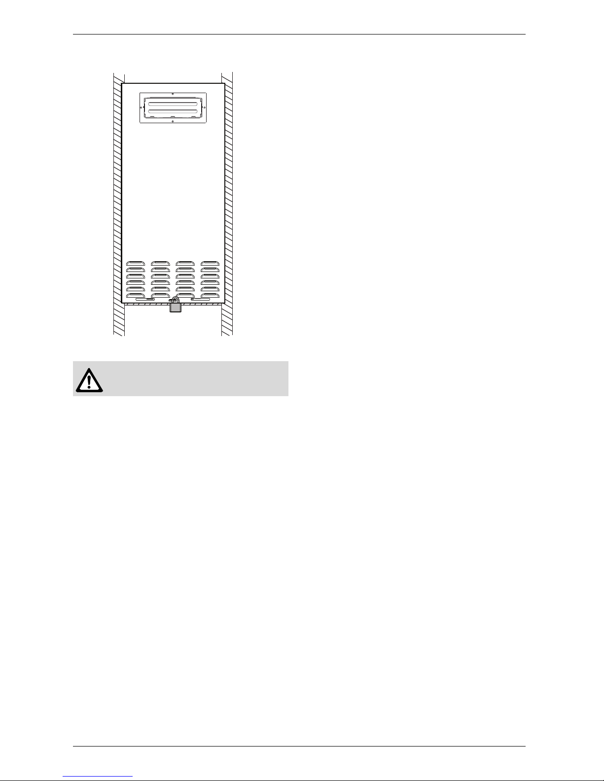
Installation using the Recess Box (7 736 500 043)
Fig. 21 Close the recess box cover with Padlock
Warning: Appliance must be installed
vertically.
6720644956-08.1V
6 720 644 956
Installation instructions
17
6 Installation instructions
6.1 Gas piping & connections
Before connecting the gas supply, check the rating
plate on the right side of the heater to be sure that the
heater is rated for the same gas to which it will be connected.
In the United States: The installation must conform with
local codes or, in the absence of local codes, the
National Fuel Gas Code ANSI Z223.1/NFPA 54.
In Canada: The Installation must conform to CSA B149
INSTALLATION CODES and/or local installation
codes.
GAS CONNECTIONS
B Install a manual gas shut off valve on the gas supply
line within easy reach of the appliance.
B Install a union when connecting gas supply.
B The minimum internal diameter required for
any appliance connector is ¾”, see Fig. 24 for
more details on pipe sizing.
B Undersized flexible appliance connector not permit-
ted.
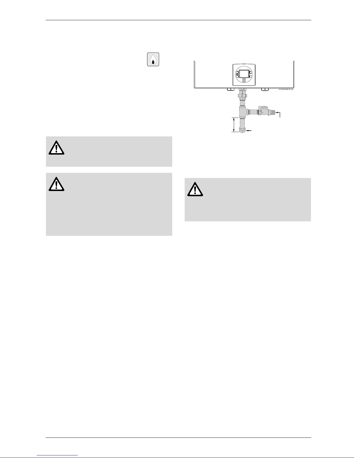
B National Fuel Gas Code requires that a sediment
trap (drip leg) be installed on gas appliances not so
equipped. The drip leg must be accessible and not
subject to freezing conditions. Install in accordance
with the recommendations of the serving gas
supplier, see Fig. 22.
Fig. 22 Gas connection (drip leg)
Once connections are made, check for gas leaks at all
joints. Apply some gas leak detection solution to all gas
fittings. Bubbles are a sign of a leak. A combustible gas
detector may also be used to detect for leaks.
Warning: DO NOT connect to an
unregulated or high pressure propane
line or to a high pressure commercial
natural gas line.
Warning: The heater must be isolated
from the gas supply piping system
during any pressure testing of that
system at test pressures equal to or
more than 0.5 psig. If overpressure has
occurred, such as through improper
testing of the gas lines or malfunction of
the supply system, the gas valve must
be checked for safe operation.
Danger: If you have a leak, shut off the
gas. Tighten appropriate fittings to stop
leak. Turn the gas on and check again
with a gas leak detection solution.
Never test for gas leaks using a match
or flame.
Gas supply
Cap
Minimum
3”
6 720 644 956
18
Installation instructions
GAS LINE SIZING
The gas supply piping for a single heater should be
sized for a maximum draw of 199,000 BTUH. Measure
the length of gas supply line and use the tables in
Fig. 24, page 19 or the gas line manufacturer’s sizing
tables to determine the pipe diameter necessary to
accommodate the 199,000 BTU demand of the heater.
If there are more gas appliances on the line, size the gas
line according to the total maximum amount of BTU
input rating for all appliances.
Note: Undersizing the gas line may result in diminished
hot water flow rate and temperature. See chapter 6.6,
page 24 for the procedure to confirm gas pressure.
Proper gas pressure must be confirmed at time of
installation.
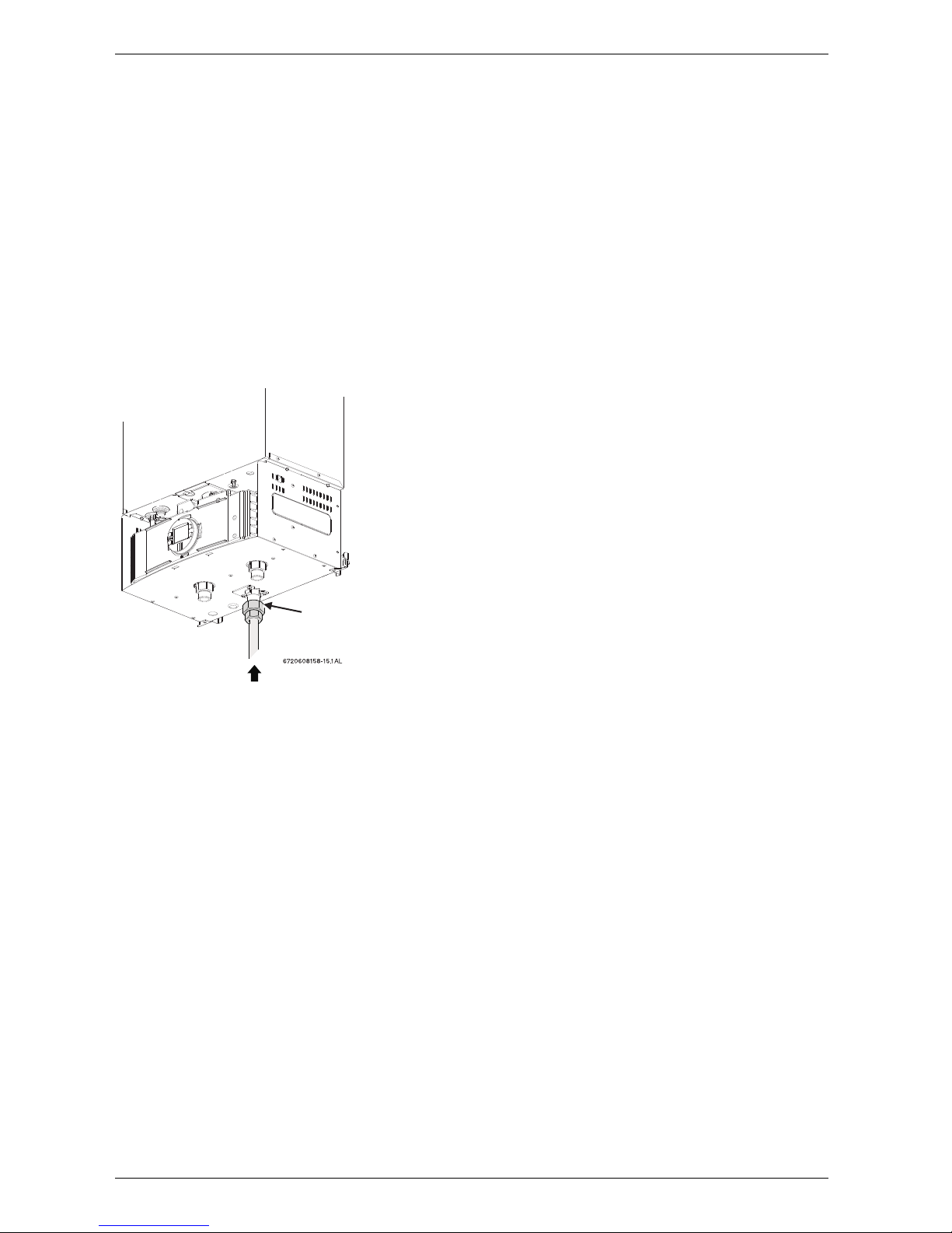
Fig. 23
Gas piping
Inlet gas particle screen
(included)
 Loading...