

Bosch 940 ES, 830 ES Installation Manual
940 ES
INDOOR MODEL
Temperature Modulated with Electronic Ignition
Suitable for heating potable water only and space heating
(Intended for variable flow applications)
940 ES - Natural Gas
940 ES - Liquefied Petroleum (LP) Gas
6 720 644 930 (2012/02) US
Warning: If the information in this manual is not
followed exactly, a fire or explosion may result
causing property damage, personal injury or death.
Do not store or use gasoline or other flammable
vapors and liquids in the vicinity of this or any other
appliance.
Improper installation, adjustment, alteration,
service or maintenance can cause injury or
property damage. Refer to this manual. For
assistance or additional information consult a
qualified installer, service agency or the gas
supplier.
In the Commonwealth of Massachusetts this
product must be installed by a licensed plumber or
gas fitter.
Upon completion of the installation, these
instructions should be handed to the user of the
appliance for future reference.
What to do if you smell gas
• Close gas valve. Open windows.
• Do not try to light any appliance.
• Do not touch any electrical switch; do not use any
phone in your building.
• Immediately call your gas supplier from a neighbor’s
phone. Follow the gas supplier’s instructions.
• If you cannot reach your gas supplier, call the fire
department.
• Installation and service must be performed by a
qualified installer, service agency or the gas supplier.

6 720 644 930
2
Index
Index
1Warning 3
2 Appliance details 4
2.1 Features 4
2.2 Specifications (Technical data) 5
2.3 Unpacking the heater 6
2.4 General rules to follow for safe operation 7
2.5 Dimensions and Minimum
installation clearances 8
3 Installation instructions 9
3.1 Specialized tools 9
3.2 Introduction 9
3.3 Venting 9
3.4 Combustion air requirements 23
3.5 Proper location for installing your heater 24
3.6 Heater placement and clearances 24
3.7 Mounting installation 24
3.8 Mounting installation for manufactured
(mobile) homes 26
3.9 Gas piping & connections 26
3.10 Water connections 29
3.11 Water quality 29
3.12 Domestic hot water recirculation 30
3.13 Space heating applications 31
3.14 Measuring gas pressure 33
4 Electrical connections 34
4.1 Electrical power supply 34
4.2 Position of the fuses in control unit 34
5 Operation instructions 35
5.1 Description LCD display 35
5.2 For your safety read before operating
your water heater 36
5.3 Power 36
5.4 Temperature selection 36
5.5 Use of optional remote control accessory
(part no. TSTAT2) 37
5.6 Operation 37
5.7 Reset button 37
5.8 Program button 37
5.9 Locked condition 38
6 Maintenance and service 38
6.1 Annual maintenance 38
6.2 Winterizing for seasonal use 39
6.3 Mineral scale build-up 39
6.4 Adjusting CO2 40
6.5 Program values 42
6.6 Diagnostic menu 43
7 Troubleshooting 44
7.1 Introduction 44
7.2 Burner do not ignite when hot water
is turned ON 44
7.3 Water is too hot 44
7.4 Water is not hot enough 44
7.5 Low water flow/pressure 45
7.6 Hot water temperature fluctuates at tap 45
7.7 Noisy burner/heater during operation 45
8 Problem solving 46
8.1 Error code diagnostics 46
9 Electrical diagram 50
10 Sensor resistance charts 51
11 Functional scheme 52
12 Interior components diagram
and parts list 53
12.1 Interior components 53
12.2 Components diagram 55
13 Protecting the environment 61
14 LIFETIME LIMITED WARRANTY
FOR BOSCH TANKLESS
WATER HEATERS 62
6 720 644 930
Warning
3
1 Warning
For your safety
Do not store or use gasoline or other flammable,
combustible or corrosive vapors and liquids in the
vicinity of this or any other appliance.
Warning: Carefully plan where you
install the heater. Correct combustion
air supply and flue pipe installation are
very important. If a gas appliance is not
installed correctly, fatal accidents can
result, such as carbon monoxide
poisoning or fire.
Warning: Exhaust gas must be vented
to outside using stainless steel vent
material suitable for category III vent
systems and temperatures up to 480°F.
Vent piping must be sealed gas-tight to
prevent possibility of flue gas spillage,
carbon monoxide emissions and risk of
fire, resulting in severe personal injury
or death. Approved vent terminators
must be used when penetrating to the
outside.
Warning: Place the heater in a location
where water leaks will do NO DAMAGE
to adjacent areas or lower floors.
Warning: Field wiring connections and
electrical grounding must comply with
local codes, or in the absence of local
codes, with the latest edition of the
National Electric Code, ANSI/NFPA 70,
or in Canada, all electrical wiring must
comply with the local codes and the
Canadian Electrical Code, CSA C22.1
Part 1.
Warning: Shock hazard: line voltage is
present. Before servicing the water
heater, unplug power supply cord from
outlet. Failure to do so could result in
severe personal injury or death.
Warning: The heater must be
disconnected from the gas supply
piping system during any pressure
testing of that system at test pressures
equal to or more than 0.5 psig.
Warning: The appliance should be
located in an area where leakage of the
heater or connections will not result in
damage to the area adjacent to the
appliance or to lower floors of the
structure. When such locations cannot
be avoided, it is recommended that a
suitable drain pan, adequately drained,
be installed under the appliance. The
pan must not restrict combustion air
flow.
Warning: The maximum inlet gas
pressure must not exceed the value
specified by the manufacturer and the
minimum value listed is for the purpose
of input adjustment.
Warning: If a water heater is installed in
a closed water supply system, such as
one having a backflow preventer in the
cold water supply line, means shall be
provided to control thermal expansion.
Contact the water supplier or local
plumbing inspector on how to control
this situation.
Warning: Keep appliance area clear
and free from combustible materials,
gasoline and other flammable vapors
and liquids.
Warning: Do not obstruct the flow of
combustion and ventilation air.
Warning: Precautions must be taken
prior to manually operating the relief
valve to avoid contact with hot water
coming out of the relief valve and to
prevent water damage.
Caution: Label all wires prior to
disconnection when servicing controls.
Wiring errors can result in improper and
dangerous operation.
Verify proper operation after servicing.
6 720 644 930
4
Appliance details
FCC:
This device complies with Part 15 of the FCC rules.
Operation is subject to the following two conditions: (1)
This device may not cause harmful interference, and (2)
this device must accept any interference received,
including interference that may cause undesired operation.
Fig. 1
2 Appliance details
2.1 Features
Parts
• Key Pad interface control
• High power pre-mix compact burner with low NOx
emissions
• Modulating Gas Valve with constant gas:air ratio
control
• Modulating water valve for improved comfort and
temperature control.
High quality materials for long working life
• Copper heat exchanger
• High efficiency Ceramat Burner
• Compact space saver: mounts on a wall with a
supplied bracket.
Features
• Real-time diagnostics for troubleshooting/
informational purposes
• LCD Display with backlight
• On/Off and Temperature control switches
• Reset button
• Program button (Selectable temperature default)
Warning: If a relief valve discharges
periodically, this may be due to thermal
expansion in a closed water supply
system. Contact the water supplier or
local plumbing inspector on how to
correct this situation. Do not plug the
relief valve.
Warning: If the water heater is used in
a space heating application, all piping
and components connected to the
water heater must be suitable for use
with potable water.
Warning: Toxic chemicals, such as
those used for boiler treatment, shall not
be introduced into the potable water
used for space heating.
Warning: A water heater which will be
used to supply potable water shall not
be connected to any heating system or
component(s) previously used with a
nonpotable water heating appliance.
Warning: Installation in mobile homes
shall conform to Title 24 CFR, Part
3280 and/or CAN/CSA Z240 MH Series, Mobile Homes.
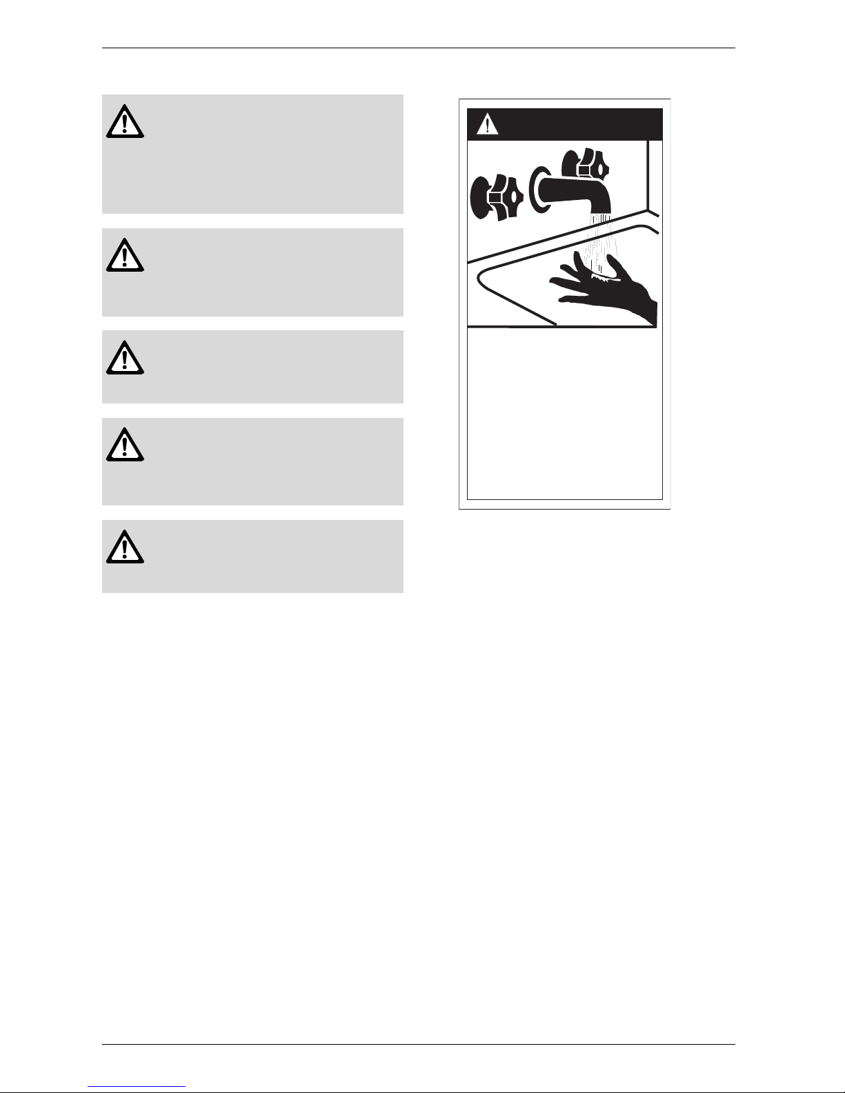
HOT
BURN
DANGER
Water temperature over 125°F can
cause severe burns instantly or
death from scalds.
Children, disabled and elderly are
at highest risk of being scalded.
See instruction manual before
setting temperature at water
heater.
Feel water before bathing or
showering.
6720608643-16.1AL

6 720 644 930
Appliance details
5
• Failure codes for easy diagnostics and repair
• Easily removable one-piece cover
• Built in freeze prevention.
Note: The freeze prevention kit is designed to provide
protection for the water heater down to approximately
5°F for short term conditions only. It will not protect the
appliance in areas where the temperature is routinely
expected to be below freezing.
- The freeze prevention kit will not protect plumbing outside the appliance from freezing. Precautions should be
taken.
Accessories (Bosch part #)
• Optional wireless remote control accessory to
operate with the appliance (TSTAT2)
• Cascading kit (77090003962)
• Outdoor kit (BTOK)
• External water filter (8703305356)
• Gas conversion kit (8719002176)
• Vertical vent kit (ESVVT)
• Concentric vent /air intake kit (ESHCK)
• Horizontal vent kit (4TWHVK3SII)
1)
• Stainless steel bird screen (L2594)
(fits into a 3” PCV fitting - Intake vent).
• Pipe Cover (PTPCES)
• High temperature kit (7736500074)
• Recess box kit (7736500043)
• Pressure relief valve (FWL-2).
2.2 Specifications (Technical data)
Approved in US/Canada
Capacity
Maximum flow rate: 7.15 GPM (27 l/min) at a 45°F
(25°C) rise.
Maximum output
160,500 Btu/h (47.0 kW)
Maximum input
199,000 Btu/h (58.3 kW)
Efficiency in %
Thermal efficiency > 82%
Min. Input
19,900 Btu/h (5.8 kW)
Temperature Control
Selection range: 100°F (38°C) - 140°F (60°C)
Default temperature: 122°F (50°C)
Stability: +/- 2°F (+/- 1°C)
Gas Requirement
Gas connection (inches) - ¾”
Inlet gas pressure under operation (with a high hot
water flow rate)*
• Propane: 8” - 13” water column.
• Natural Gas: 3.5” - 10.5” water column.
* To measure gas pressure, see Measuring Gas
Pressure, chapter 3.14, page 33.
Water
• Hot water connection (inches) - ¾”
• Cold water connection (inches) - ¾”
• Water valve material: Polymer (PPS) (Polypropylene
Sulfid)
• Minimum water flow: 0.5 gallon/minute (1,9 l/m).
Note: Activation varies with inlet water temperatures
from 0.5 - 1.6 gallon/minute (1,9 - 6.1 l/m).
• Minimum recommended water pressure: 30 PSI
(2.07 bar).
• Minimum well pressure 40 psi, see page 29.
• Connections:
– Bottom of heater
Combustion
• Design is NOx compliant with SCAQMD requirements - rule 1146,2 approved type 1 appliances
.
•CO 250 ppm (measured)
•CO
2
level set from factory, see chapter 6.4, page 40.
1) 4TWHVK3S vent kit is compatible with this appliance
but requires the purchase of an additional 12" piece of
straight pipe to meet minimum vent length requirements.
The aluminum flex piping included with this kit is not
permissible for use with this appliance.
i
BOSCH is constantly improving its
products, therefore specifications are
subject to change without prior notice.
6 720 644 930
6
Appliance details
Dimensions
• Depth (in): 11¼” (286 mm)
• Width (in): 17
7
/
8
” (452 mm)
• Height (in): 30½” (775 mm)
• Weight: 67 pounds (30.5 kg).
Gas types
Natural Gas.
LP Gas.
Voltage
120 V AC (60 Hz) nominal
Amperage
Idle - 40 mA
Operation - 2.5 A
Noise
45 - 65 db (A)
Safety devices
• Flame failure device (ionization flame rod sensor)
• Over heat prevention (temperature limiter)
• Inlet temperature sensor
• Outlet temperature sensor
• Back flow temperature sensor.
Water protection
IP X4 (protection against water drops)
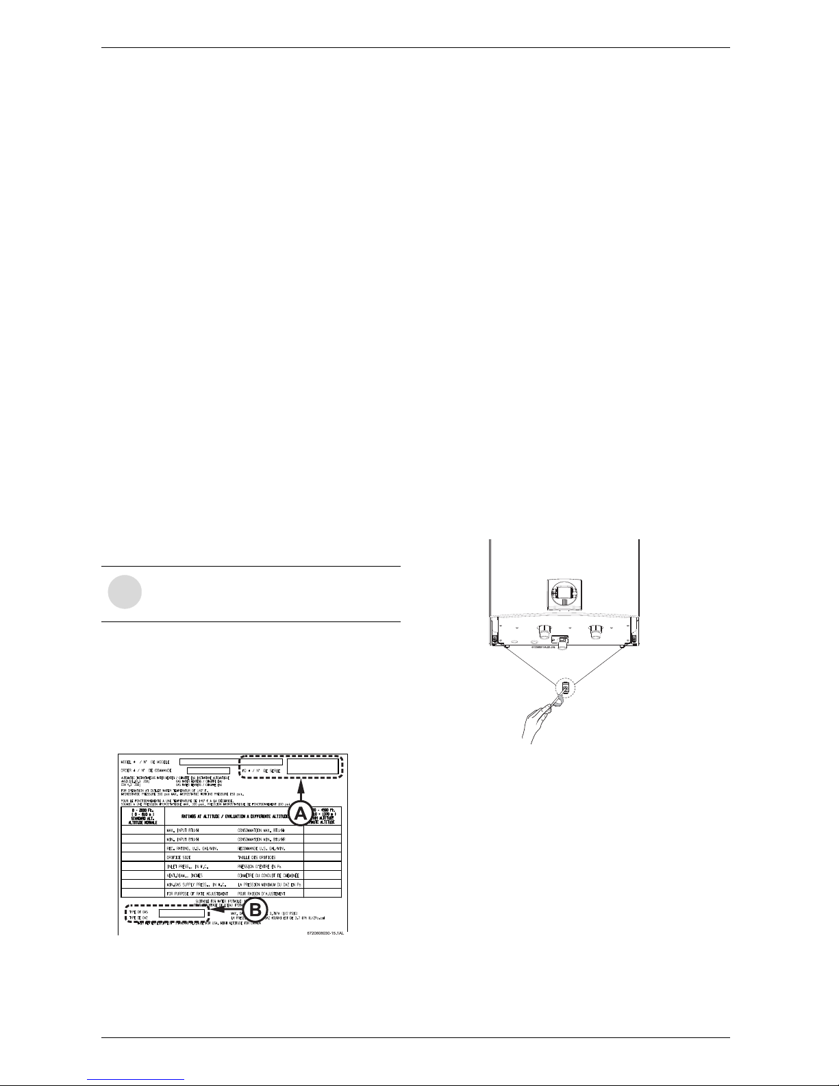
2.3 Unpacking the heater
Before installing the unit, be certain you have the
correct heater for your type of Gas: Propane or
Natural Gas. Identification labels are found on the
shipping box, and on the rating plate which is located on
the right side panel of the cover.
Fig. 2 Rating plate
A Serial number
B Type of gas
The box includes:
•940 ES
• Bracket for wall hanging the heater
• Exhaust vent adaptor (with 4 screws and gasket
provided)
• Combustion air inlet adaptor (with 3 screws and gasket provided)
• Installation manual (manual can be downloaded at
www.bosch-climate.us)
• Product registration card.
Please complete and return the enclosed product
registration card.
The 940 ES is not approved or designed for:
• Recreational vehicle (RV) or boat installations.
• Use above 8000 ft A.S.L. altitude (see page 20).
• Outdoor installation without installation of
Outdoor kit (BTOK).
• Applications where inlet water temperature is
higher than 140ºF (60°C). A 3-way valve or
mixing valve must be installed before the
appliance if inlet water temperature exceeds
this limit.
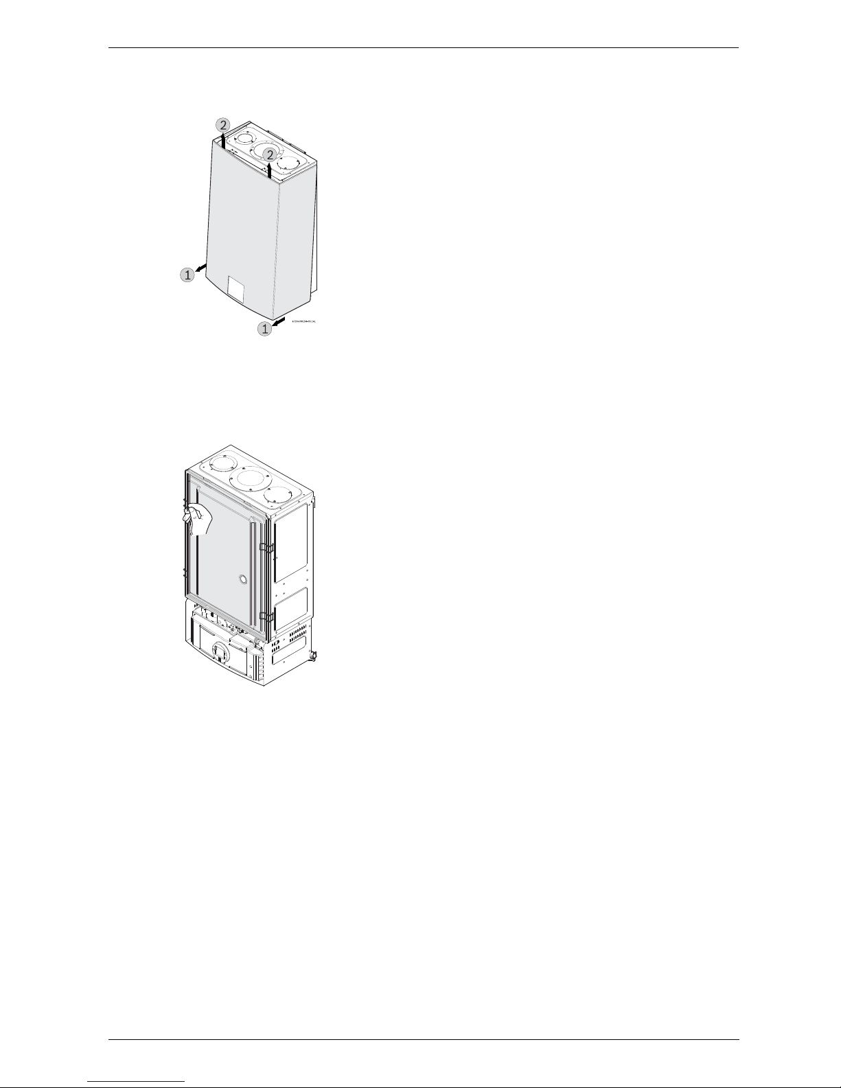
To remove front cover
B Loosen the two Philips head screws located on
bottom rear of cover (see Fig. 3).
Fig. 3 Loosen the two screws
i
If appliance is installed at elevations above
2000ft, refer to Section 3.3.8 Fan speed
adjustment.
6 720 644 930
Appliance details
7
B Lift front cover panel upward and remove.
Fig. 4 Remove the front cover
To remove combustion cover (service only)
B Open the four clips and remove the combustion
cover see Fig. 5.
Fig. 5 Remove the combustion cover
2.4 General rules to follow for safe
operation
B 1. You must follow these instructions when you install
your heater. In the United States: The installation must
conform with local codes or, in the absence of local
codes, the National Fuel Gas Code ANSI Z223.1/
NFPA 54.
In Canada: The Installation must conform with CGA
B149.(1,2) INSTALLATION CODES and /or local
installation codes.
B 2. Carefully plan where you install the heater. Correct
combustion air supply and vent pipe installation are
very important. If not installed correctly, fatal
accidents can occur, such as carbon monoxide
poisoning or fire.
B 3. When the unit is installed indoors and ROOM
SEALED (twin pipe) it is permitted to be located in
bathrooms, bedrooms and occupied rooms that are
normally kept closed. See chapter
3.3 (page 9). If the
unit will be installed indoors and use indoor
combustion air, the place where you install the heater
must have enough ventilation. The National Fuel
Gas Code does not allow UNSEALED gas fired
water heater installations in bathrooms,
bedrooms or any occupied rooms normally
kept closed. See chapter
3.5, page 24 and 3.4,
page 23.
B 4. You must vent your heater. See chapter 3.3, page
9
on VENTING.
B 5. The appliance and its gas connection must be leak
tested before placing the appliance in operation.
The appliance must be isolated from the gas supply
piping system by closing its individual manual gas
shutoff valve (not supplied with heater) during any
pressure testing at pressures in excess of ½ Psig (3.5
kPa).
B 6. Keep water heater area clear and free from
combustibles and flammable liquids. Do not locate
the heater over any material which might burn.
B 7. Correct gas pressure is critical for the proper
operation of this heater. Gas piping must be sized to
provide the required pressure at the maximum output
of the heater, while all the other gas appliances are in
operation. Check with your local gas supplier, and
see the section on connecting the gas supply, see
chapter 3.9.
B 8. Should overheating occur or the gas supply fail to
shut off, turn off the gas supply at the manual gas shut
off valve, on the gas line. Note: manual gas shutoff
valve is not supplied with the heater but must be field
installed.
B 9. Do not use this appliance if any part has been
underwater. Immediately call a qualified service
technician to inspect the appliance and to replace any
part of the control system and any gas control which
has been underwater.
B 10. Failure to install heater correctly may lead to
unsafe operation and void the warranty.
6720644956-11.1V
6 720 644 930
8
Appliance details
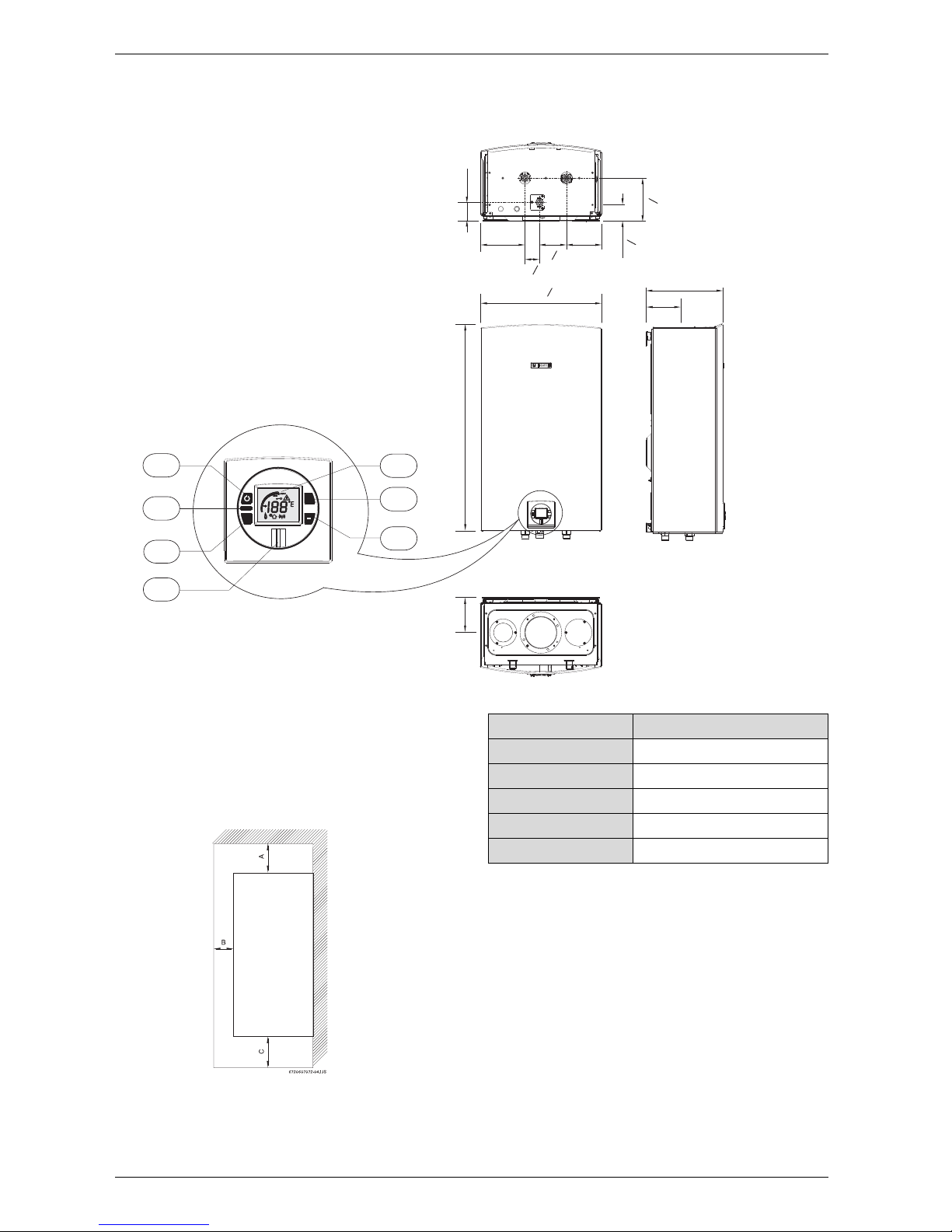
2.5 Dimensions and Minimum installation clearances
Fig. 6 Dimensions
1 On/Off button
2 Reset button
3 Program key
4 Power ON or stand-by LED
5 LCD display
6 Up button
7 Down button
Fig. 7 Minimum clearances
Note: For servicing access, a 2ft clearance to front
cover is recommended.
6720608158-04.2AL
2
3
1
6
5
7
4
reset
P
+
5¼"
30 ½"
17 "
7
8
5¼"
11 ¼"
2 ¾"
6 ½"
2 "
16
5
5¼"
2 "
16
4 "
1
16
6 "
5
16
1
16
5
16
Model 940 ES
TOP (A) 12”
FRONT (B) 1”
BACK 0”
SIDES 1”
FLOOR (C) 12”
Table 1 Minimum clearances
6 720 644 930
Installation instructions
9
3 Installation instructions
3.1 Specialized tools
The following specialized tools may be required for
installation:
• Manometer
• Multi-meter
• Combustion Gas Analyzer.
3.2 Introduction
Please follow these instructions. Failure to follow
instructions may result in:
B Damage or injury.
B Improper operation.
B Loss of warranty.
If you are unable to perform the tasks required to install
this heater properly, please contact a locally licensed
plumber or gas technician.
3.3 Venting
3.3.1 Vent material
Establish vent clearances that comply with the vent
manufacturer's specifications. In all cases, follow local
codes. See Table 2.
Horizontal venting systems only:
An optional stainless concentric vent/air intake
termination can be used to provide only one penetration
point through the exterior wall (see Fig. 8, 9 & 10). The
concentric vent/air intake kit can be ordered from your
local wholesaler. (Part# ESHCK). Note: Only tee
terminals are approved for use with the
concentric vent/air intake kit (see Table 3). Vent
piping and tee terminal used with kit must be
from the same vent pipe manufacturer. The
appliance can also be installed with separate air
intake and exhaust piping (see Fig. 16 ).
i
Common installation practice is to determine the venting/intake system layout and
penetration and then work back to the
heater.
Warning: Do not reduce the vent
(exhaust and combustion) pipe sizes
and do not common vent with any other
vented appliance or stove.
Warning: Failure to vent the exhaust
gases to the outside with sealed
stainless steel vent pipe (AL29-4C)
may result in dangerous flue gases
filling the structure in which it is
installed.
Warning: Do not mix vent pipe or
joining methods from different
manufacturers.
Warning: Approved terminators must
be used for inlet and exhaust vent systems to prevent rain from entering the
appliance. Failure to do so may result in
damage to the appliance. This failure is
not covered under the manufacturer’s
warranty.
Caution: The vent system must be
installed by a qualified installer in
accordance with these instructions. If
improperly installed, a hazardous
condition such as explosion or carbon
monoxide poisoning could result.
Bosch Water Heating will not be
responsible for improperly installed
appliances.
Warning: In areas where outside
temperatures routinely come close to
freezing, sealed combustion operation
is required. Use separate terminations
for combustion and vent, which must be
installed on the same wall or roof
surface, however never facing the
direction of prevailing winds. Failure to
do so may result in heat exchanger
freezing up and bursting. This failure is
not covered under the manufacturer's
warranty.
Diam. Material
Exhaust
Vent
3 or 4 inches Sealed single wall stainless steel
(AL29-4C)
Intake
Vent
3 or 4 inches Sealed PVC or any other rigid pipe
Table 2 Venting Specifications
6 720 644 930
10
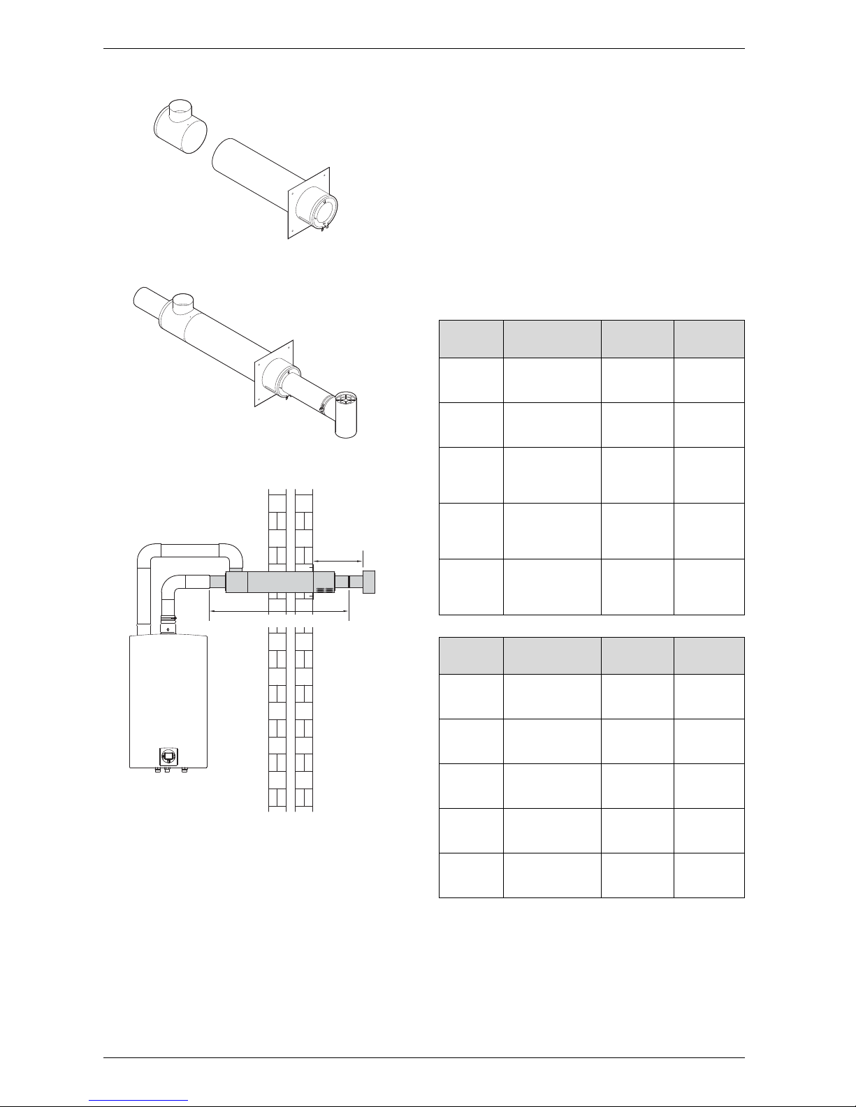
Installation instructions
Fig. 8 Concentric kit part # ESHCK
Fig. 9 Concentric kit vent assembly
Fig. 10 Concentric kit installation
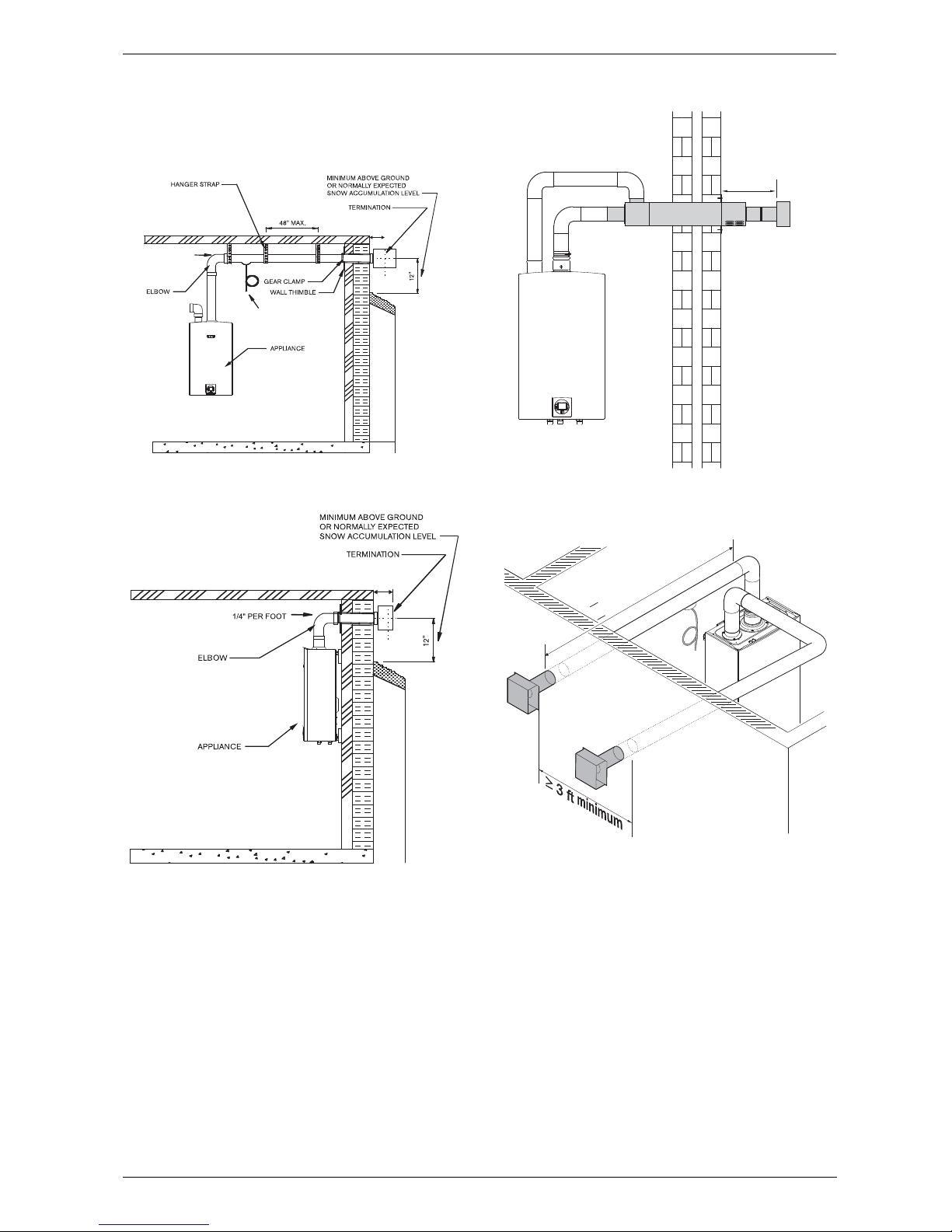
3.3.2 Venting Specifications
Install appliance as close to point of vent termination as
possible. The exhaust piping must vent directly to the
outside of the structure.
Horizontal sections of vent must pitch upward towards
termination ¼" for every foot of horizontal length, to
prevent the pooling of condensate, and be supported at
4 foot intervals with overhead hangers.
Exception: horizontal run between last elbow and
termination must pitch down to termination 1/4" per
foot. Note: For horizontal terminations, venting must
terminate once it penetrates to the outside of the
structure. There must be no sections of vent pipe
exposed to the outdoors other than the termination.
Note: Listed thimbles or collars are necessary where
venting passes through wall and ceiling partitions. If the
vent system passes through combustible areas where
the vent clearance requirements cannot be maintained,
it is permissible to chase straight sections of sealed 3
inch single wall vent through 4 inch (or greater) Type-B
vent. The distance to combustibles using this chase
technique is 1 inch. Note: Type-B vent must never be
used as the actual exhaust vent system for the
appliance, as it is not gas tight and illegal for use with
this appliance. This will create a serious health hazard
and void the warranty.
For specific questions concerning vent material, specifications, usage or installation, please contact the vent
manufacturer directly.
6720608782-09.1Av
6720608782-10.1Av
12"
6720608782-11.1Av
3” stainless steel pipe
3”
VENTING
Z flex Protech Heat Fab
3"
90° elbow
2SVEEWCF0390 FSELB9003 9314
3" Tee
Terminal
2SVSTTF03 FSTT3 9390TEE
3”
Horizontal
Terminal
2SVSTB03 FSTB3 N/A
3" horiz.
terminal
with damper
2SVSHTD03 N/A N/A
3” Vertical
Terminal
2SVSRCF03 FSRC3 5300CI
Table 3 3" Terminator Part Numbers
4”
VENTING
Z flex Protech Heat Fab
4"
90° elbow
2SVEEWCF0490 FSELB9004 9414
4" Tee
Terminal
2SVSTTF04 FSTT4 9490TEE
4”
Horizontal
Terminal
2SVSTB04 FSTB4 N/A
4" horiz.
terminal
with damper
2SVSHTD04 FSRC4 5400CI
4"
vertical
terminal
2SVSRCF04 N/A N/A
Table 4 4" Terminator Part Numbers
6 720 644 930
Installation instructions
11
Condensate drain requirements
An external condensate drain (not supplied with the
heater) must be installed under the following
conditions:
• All vertical terminating vent installations.
• Horizontal terminating vent installations where the
total linear vent length is greater than 10 feet (3.1 m)
for 3" and 5 feet (1.5 m) for 4".
• Vent installations where any section of the exhaust
vent pipe passes through an unconditioned space.
Twin pipe termination clearances
The minimum clearance between exhaust vent and
combustion air inlet terminations for twin pipe
penetration is 3 feet.
Minimum combustion air and exhaust pipe
length
The minimum exhaust pipe length is 1 foot (0.3m) of
straight vent pipe. The minimum combustion air pipe
length is one 90° elbow.
Maximum combustion air and exhaust pipe
length
The following tables display the maximum allowable
straight pipe lengths for combustion air and exhaust
piping with consideration to the number of elbows
used. Reduce the equivalent length for each elbow
used from the maximum allowable length.
Use of elbows
It is recommended to limit the amount of elbows used in
the exhaust and combustion air piping to reduce friction
in the air flow. The following lists the maximum amount
of 90° elbows allowed in either the exhaust or combustion air piping:
Company Contact info
Z-flex www.z-flex.com
800-654-5600
ProTech Industries www.protechinfo.com
800-766-3473
Heat-Fab www.heatfab.com
800-772-0739
Table 5 Vent manufacturers
Venting Maximum
allowable
Exhaust
pipe length
Maximum
allowable
Combustio
n air pipe
length
Elbow
Equivalency
90° 45°
3"
28.5 ft 28.5 ft 2.5 ft 1.25 ft
4"
61.25 ft 61.25 ft 1.25 ft .75 ft
Table 6 Maximum Allowable Exhaust and Combustion
Air Lengths
90° elbows
3"
Venting
4"
Venting
Max number of elbows 5 7
Table 7
i
Two 45° elbows are equal to one 90°
elbow. Any combination of 45° and
90° elbows may be used in the vent
system as long as the combination
does not exceed the maximum listed
in table 7 above.
6 720 644 930
12
Installation instructions
Calculation example for 3" venting:
Exhaust
Combustion air
Calculation example for 4" venting:
Exhaust
Combustion air
System used Concentric
Number of 90° elbows needed: 1
Number of 45° elbows needed: 2
Table 8
Calculation of example
Max. length 28.5’
90° elbow reduction - 2.5’
sub-total = 26’
45° elbow reduction - 2.5’
Total = 23.5’
Table 9
i
For this example, the maximum allowable
exhaust pipe length is 23.5 feet.
System used Concentric
Number of 90° elbows needed: 2
Number of 45° elbows needed: 1
Table 10
Calculation of example
Max. length 28.5’
90° elbow reduction - 5’
sub-total = 23.5’
45° elbow reduction - 1.25’
Total = 22.25’
Table 11
i
For this example, the maximum allowable
combustion air pipe length is 22.25 feet.
System used Twin pipe
Number of 90° elbows needed: 2
Number of 45° elbows needed: 2
Table 12
Calculation of example
Max. length 61.25’
90° elbow reduction - 2.5’
sub-total = 58.75’
45° elbow reduction - 1.5’
Total = 57.25’
Table 13
i
For this example, the maximum allowable
exhaust pipe length is 57.25 feet.
System used Twin pipe
Number of 90° elbows needed: 1
Number of 45° elbows needed: 2
Table 14
Calculation of example
Max. length 61.25’
90° elbow reduction - 1.25’
sub-total = 60’
45° elbow reduction - 1.5’
Total = 58.5’
Table 15
i
For this example, the maximum allowable
combustion air pipe length is 58.5 feet.
6 720 644 930
Installation instructions
13
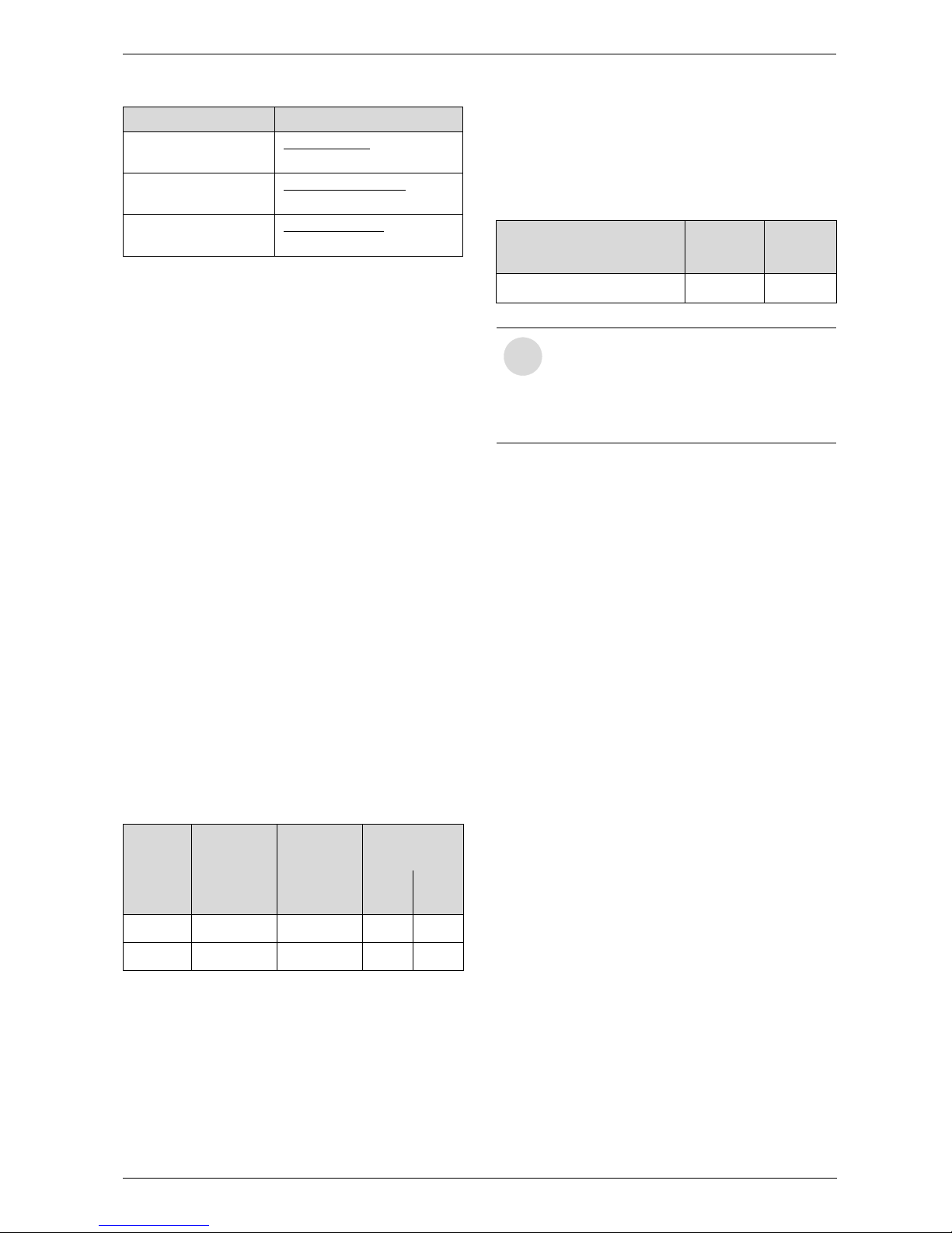
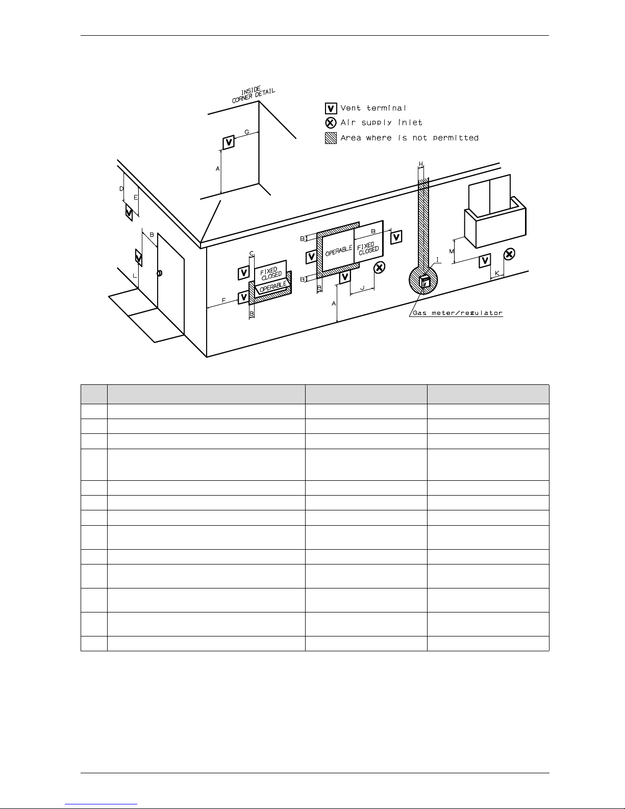
Required direct vent terminal clearances (twin pipe / concentric penetration)
Fig. 11
* For clearances not specified in ANSI Z223.1 / NFPA 54 or CSA-B149.1, one of the following shall be indicated:
a) A minimum clearance value determined by testing in accordance with section 2.20, or;
b) A reference to the following footnote:
“Clearance in accordance with local installation codes and the requirements of the gas supplier.”
6720608836-23.1Av
Canadian installations
1)
U.S. installations
2)
A Clearance above grade, veranda, porch, deck or balcony 12 in. 12 in.
B Clearance to window or door that may be opened 36 in. 12 in.
C Clearance to permanently closed window * *
D Vertical clearance to ventilated soffit located above the vent
terminator within a horizontal distance of 2 feet (61cm) from the
center line of the terminator
**
E Clearance to unventilated soffit * *
F Clearance to outside corner * *
G Clearance to inside corner * *
H Clearance to each side of center line extended above meter/
regulator assembly
36 in. within a height 15 feet above
meter/ regulator assembly
*
I Clearance to service regulator vent outlet 36 in. *
J Clearance to non-mechanical air supply inlet to building or the
combustion air inlet to any other application
36 in. 12 in.
K Clearance to mechanical air supply inlet 72 in. 36 in. above if within 10 feet
horizontally
L Clearance above paved sidewalk or paved driveway located on
public property
84 in.
3)
*
M Clearance under veranda, porch deck or balcony 12 in.
4)
*
Table 16
1) In accordance with the current CSA B149.1 Natural Gas and Propane Installation Code
2) In accordance with the current ANSI Z223.1 / NFPA 54 National Fuel Gas Code
3) A vent shall not terminate directly above a sidewalk or paved driveway that is located between two single family dwellings and serves both dwellings.
4) Permitted only if veranda, porch, deck or balcony is fully open on a minimum of two sides beneath the floor.
6 720 644 930
14
Installation instructions
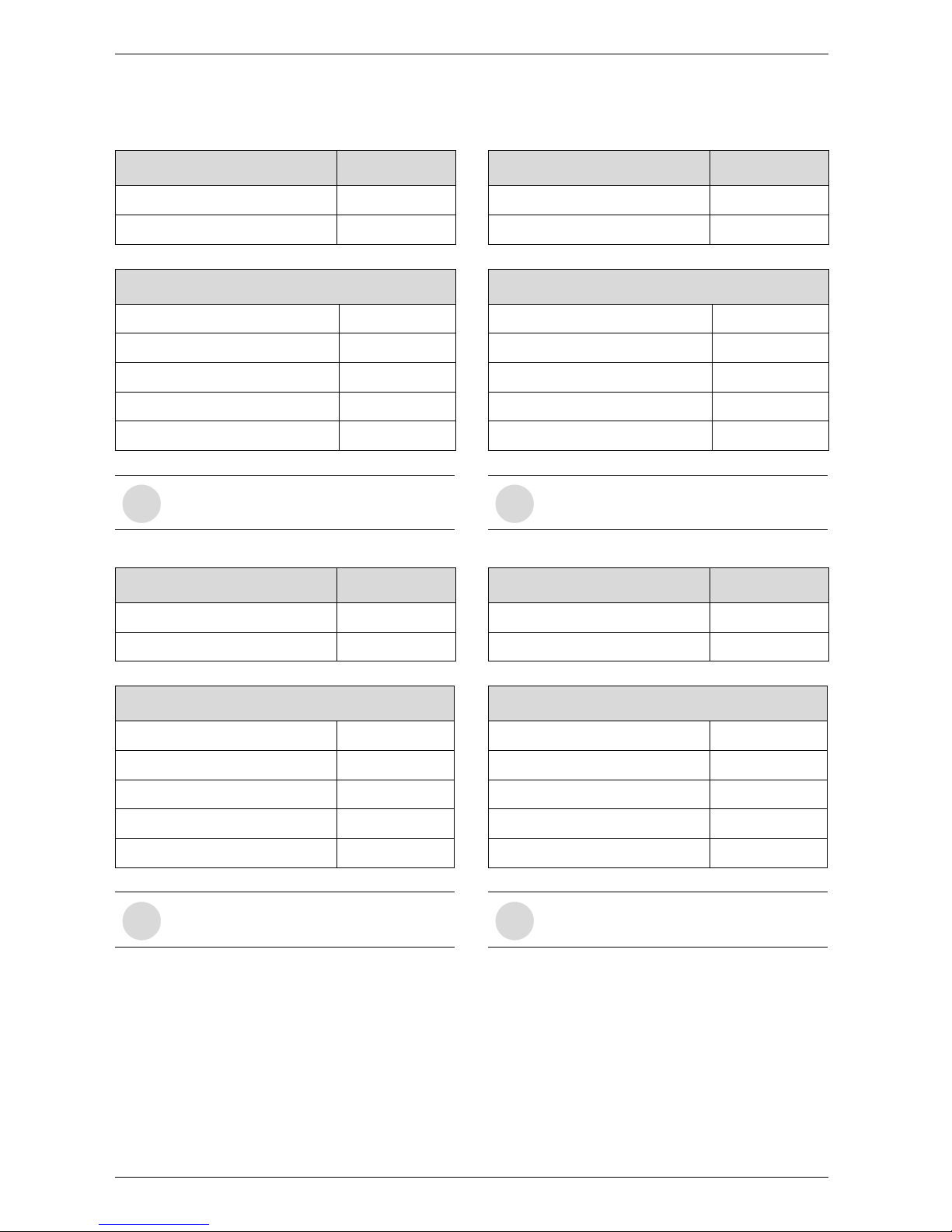
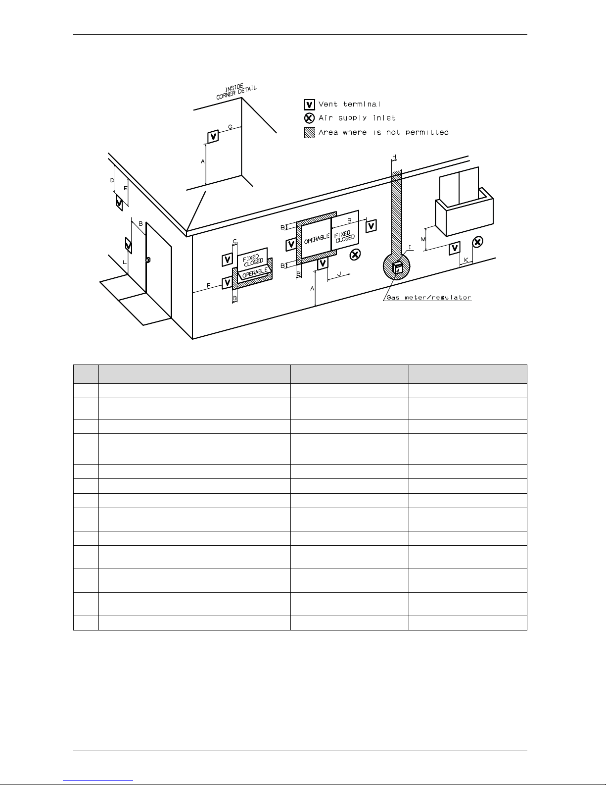
Required other than direct vent terminal clearances (single pipe penetration)
Fig. 12
* For clearances not specified in ANSI Z223.1 / NFPA 54 or CSA-B149.1, one of the following shall be indicated:
a) A minimum clearance value determined by testing in accordance with section 2.20, or;
b) A reference to the following footnote:
“Clearance in accordance with local installation codes and the requirements of the gas supplier.”
6720608836-23.1Av
Canadian installations
1)
U.S. installations
2)
A Clearance above grade, veranda, porch, deck or balcony 12 in. 12 in.
B Clearance to window or door that may be opened 36 in. 4 feet below or to side of opening;
1 foot above opening
C Clearance to permanently closed window * *
D Vertical clearance to ventilated soffit located above the vent
terminator within a horizontal distance of 2 feet (61cm) from the
center line of the terminator
**
E Clearance to unventilated soffit * *
F Clearance to outside corner * *
G Clearance to inside corner * *
H Clearance to each side of center line extended above meter/
regulator assembly
36 in. within a height 15 feet above
meter/ regulator assembly
*
I Clearance to service regulator vent outlet 36 in. *
J Clearance to non-mechanical air supply inlet to building or the
combustion air inlet to any other application
36 in. 4 feet below or to side of opening;
1 foot above opening
K Clearance to mechanical air supply inlet 72 in. 36 in. above if within 10 feet
horizontally
L Clearance above paved sidewalk or paved driveway located on
public property
84 in.
3)
84 in.
M Clearance under veranda, porch deck or balcony 12 in.
4)
*
Table 17
1) In accordance with the current CSA B149.1 Natural Gas and Propane Installation Code
2) In accordance with the current ANSI Z223.1 / NFPA 54 National Fuel Gas Code
3) A vent shall not terminate directly above a sidewalk or paved driveway that is located between two single family dwellings and serves both dwellings.
4) Permitted only if veranda, porch, deck or balcony is fully open on a minimum of two sides beneath the floor.
6 720 644 930
Installation instructions
15
3.3.3 Venting configuration examples
Below are approved examples of horizontal
venting installations.
Fig. 13 Horizontal side wall venting installation (single
pipe penetration)
Fig. 14 Horizontal venting installation (combustion air
piping not shown)
Warning: Single pipe penetration should be used in
non-freezing climates only!
Important:
Note: Pitch horizontal runs down toward the heater,
except horizontal run between last elbow and termination which must slope down to termination 1/4" per
foot.
Note: For horizontal terminations, venting must
terminate once it penetrates to the outside of the
structure. There must be no sections of vent pipe
exposed to the outdoors.
Fig. 15 Horizontal venting installation (concentric
penetration)
Fig. 16 Horizontal twin pipe penetration
Below are approved examples of vertical venting
installations.
Important:
Note: Pitch horizontal runs down toward the heater,
1/4" per foot.
4"
6720608542-02.2AL
HORIZONTALRUN
1/4" PER FOOT
DOWN TO
TERMINATOR.
CONDENSATE
DRAIN
4"
HORIZONTAL RUN
DOWN TO
TERMINATOR.
SIDE
OF
WATER
HEATER
NOTE:
MINIMUM 1FT OF
STRAIGHT VENT PIPE
REQUIRED
6720608542-10.1V
12"
6720608782-11.2V
6720608542-05.3V
<
<
26ft with 3" venting
60ft with 4" venting
6 720 644 930
16
Installation instructions
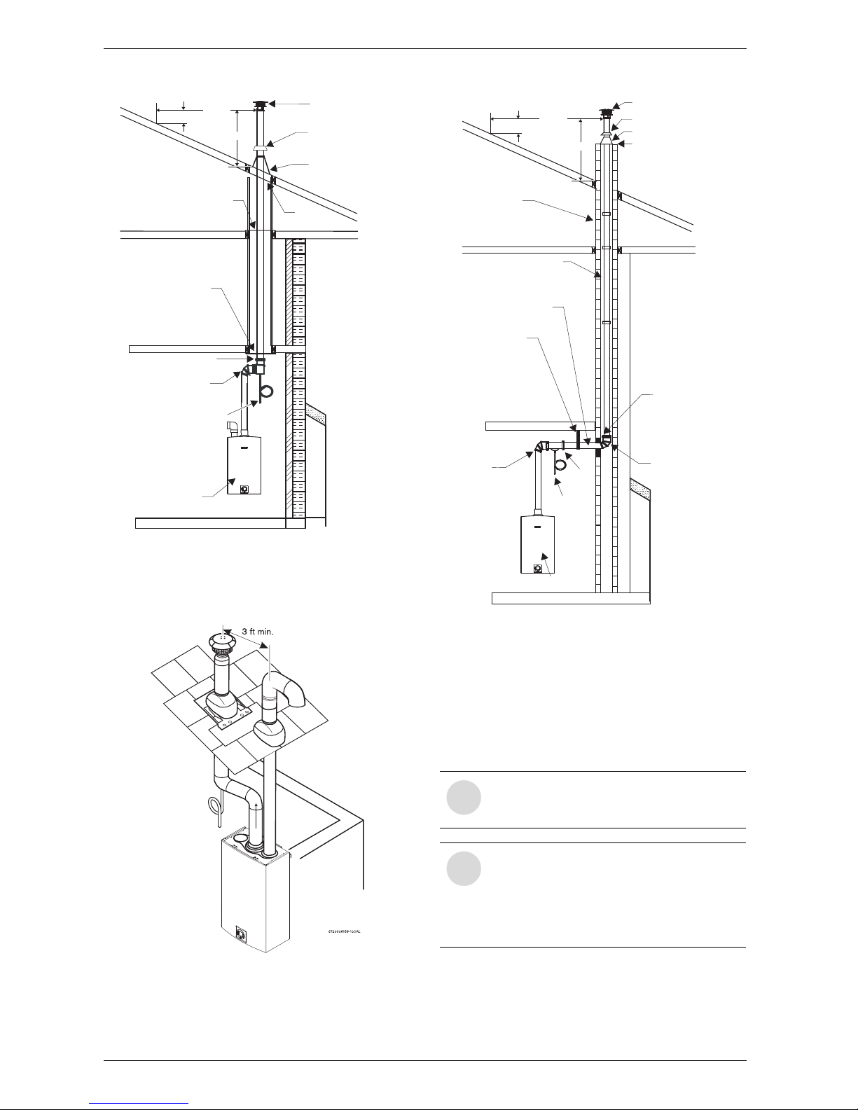
Fig. 17 Vertical venting installation (single pipe pene-
tration)
Warning: Single pipe penetration should be used
in non-freezing climates only!
Fig. 18 Vertical venting installation (twin pipe penetra-
tion)
Fig. 19 Vertical venting installation - Masonry Chim-
ney (combustion air piping not shown)
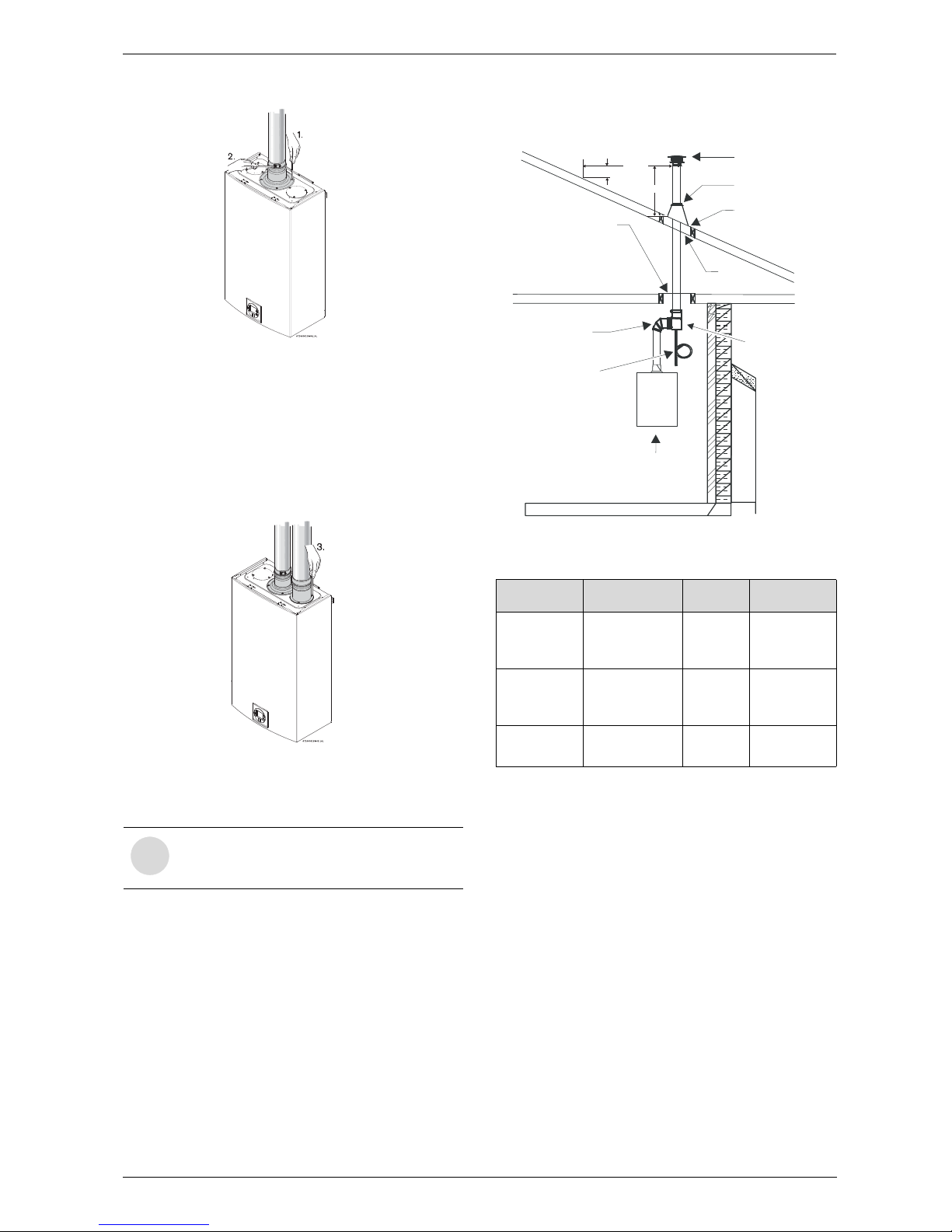
3.3.4 Vent connections
B Attach the flue gas exhaust accessory (8 705 504
151) to the top of the unit (position 1) using the 4
screws and gasket provided. Fully insert stainless
steel vent pipe 1.5” minimum into the accessory and
tighten the clamp (position 2).
FIRESTOP SUPPORT
ELBOW
APPLIANCE
HOSE
CLAMP
RAIN CAP
STORM COLLAR
FLASHING
FIRESTOP SUPPORT
4" MIN.
AIR SPACE
6720608158-91.2Av
CONDENSATE
DRAIN
2' MIN.
10' MIN.
3' MIN.
i
If using the 4” vent, a 3” to 4” increaser is
required immediately off the top of the
heater.
i
NOTE: Vent pipe must be completely vertical when inserting or gasket inside exhaust accessory can become displaced.
Exhaust accessory can be removed with
vent pipe attached to check gasket position.
CHIMNEY
MORTAR
HANGER STRAP
HORIZONTAL RUN
1/4" RISE/FT
ELBOW
APPLIANCE
MAY BE INSULATED
IF NECESSARY
6720608158-14.2AL
HOSE
CLAMP
ELBOW
RAIN CAP
STORM COLLAR
SILICONE SEAL
FLASHING
CONDENSATE
DRAIN
2' MIN.
10' MIN.
3' MIN.
6 720 644 930
Installation instructions
17
Fig. 20
B Attach the combustion air inlet accessory (8 705
504 154) to the top of the unit (position 3) using the
3 screws and gasket provided, and install air intake
pipe over the accessory. NOTE: The appliance has
the option to mount the combustion air inlet accessory on the top right or on the top left side of the
heater. The combustion air inlet that is not used must
be kept sealed.
Fig. 21
B Ensure that exhaust vent pipe is fully inserted in collar
to enable proper connection.
3.3.5 Condensate drain installation
Note: Do not install condensate drain in areas where it
may freeze.
1. Install condensate drain as close to heater as possi-
ble.
2. Use 3/8" ID high temperature silicone tube to con-
nect to condensate drain port. Do not use copper piping for any portion of the condensate drain.
3. Form a condensate trap by means of a 3" loop par-
tially filled with water.
4. To increase the tube length, connect to end of the
high temperature silicone tubing with vinyl tubing, PVC
or CPVC pipe. Do not reduce the internal diameter at
any point.
5. Dispose of condensate according to local codes.
Fig. 22 Condensate drain installation (combustion air
piping not shown)
3.3.6 Freeze prevention
In cold climates, components of a tankless water heater
can freeze and burst from negative draft. A leading
cause of negative draft is combustion appliances in the
building not being supplied with sufficient combustion
air. A wood stove or furnace can pull its combustion air
from the water heater‘s vent pipe, allowing the cold
incoming air to freeze the cold water in the heat
exchanger. Supplying more combustion air for all combustion appliances is the solution. A HVAC specialist
should be consulted to design solutions for providing
more combustion air.
Listed below are additional measures designed to further limit backdraft in extreme conditions assuming all
other possible causes have been addressed.
i
Exhaust venting must be 3" or 4" sealed
single wall stainless steel (AL29-4C) vent
pipe.
3" Venting Z-flex ProTech Heat Fab
90°
Condensate
Drain Tee
2SVEVWCF03 FST3 &
FSDF3
93PPLSTEE
Horizontal
Condensate
Drain
2SVEDWCF03 FSHDT3 9321
Condensate
Drain Tube
2SVEDTK24 N/A 7000TUBE
Table 18 Approved Condensate Drain Part Numbers
RAIN CAP
STORM COLLAR
FLASHING
4" MIN.
AIR SPACE
CONDENSATE
APPLIANCE
6720608782-04.2Av
ELBOW
FIRESTOP SUPPORT
DRAIN TRAP
TO DRAIN - DISPOSE
OF CONDENSATE
ACCORDING TO
LOCAL CODES
DRAIN TEE
2' MIN.
10' MIN.
3' MIN.
6 720 644 930
18
Installation instructions
Solution One
The Z-flex vent termination hood is the preferred option
for limiting backdraft under the following conditions
(see Fig. 23):
• The vent hood is only to be used in the exhaust vent
piping.
• The vent hood can only be used for horizontal terminations.
• The vent hood is able to meet the required clearances outlined in the venting section of the water
heater‘s installation manual.
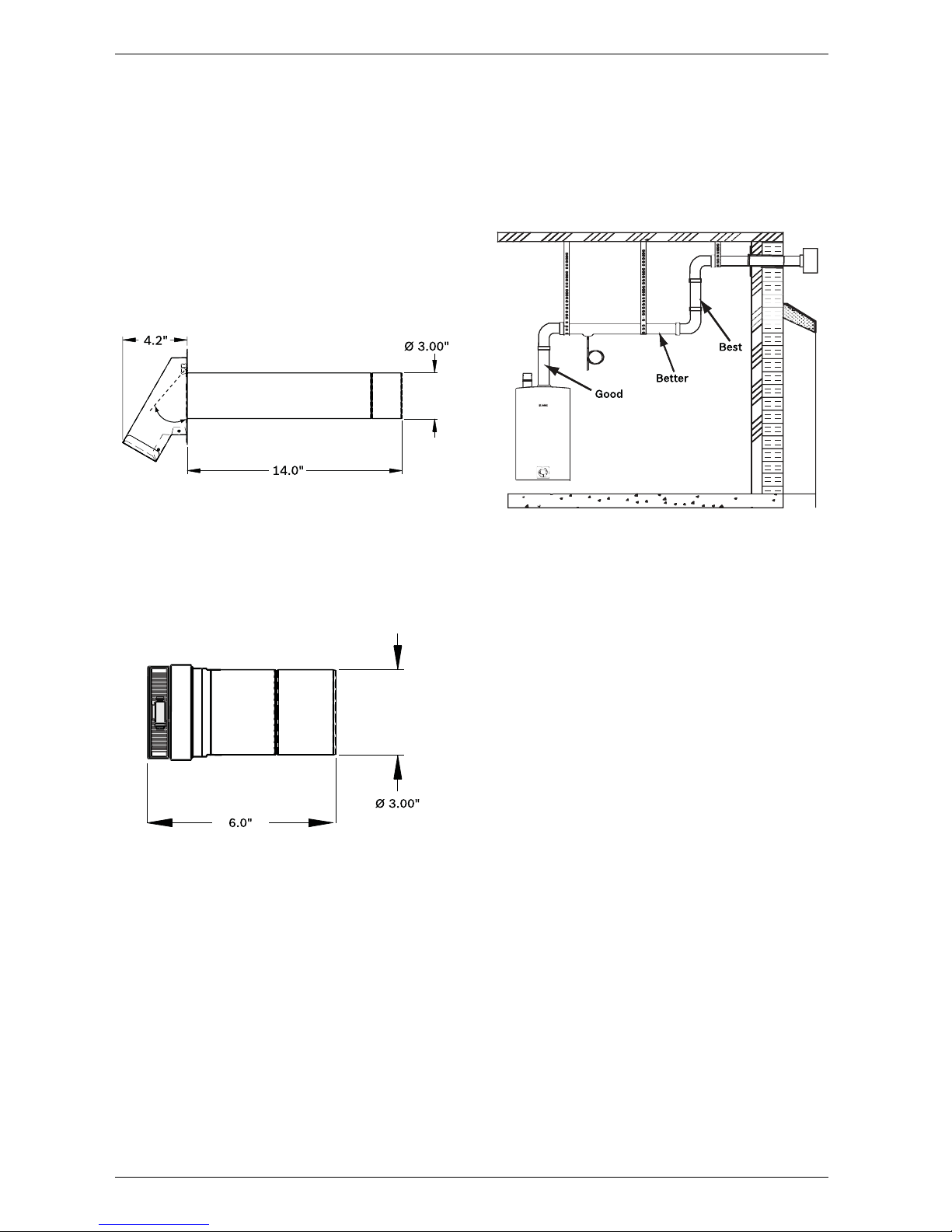
Fig. 23 Part nr. 2SVSHTD03 for 3" venting
Part nr. 2SVSHTD04 for 4" venting
Solution Two
If the required clearances of the Zflex termination hood
cannot be met, the Zflex damper is the preferred alternative (see Fig. 24).
Fig. 24 Part nr. 2ZVBP03 for 3" venting
Part nr. 2ZVBP04 for 4" venting
Installation
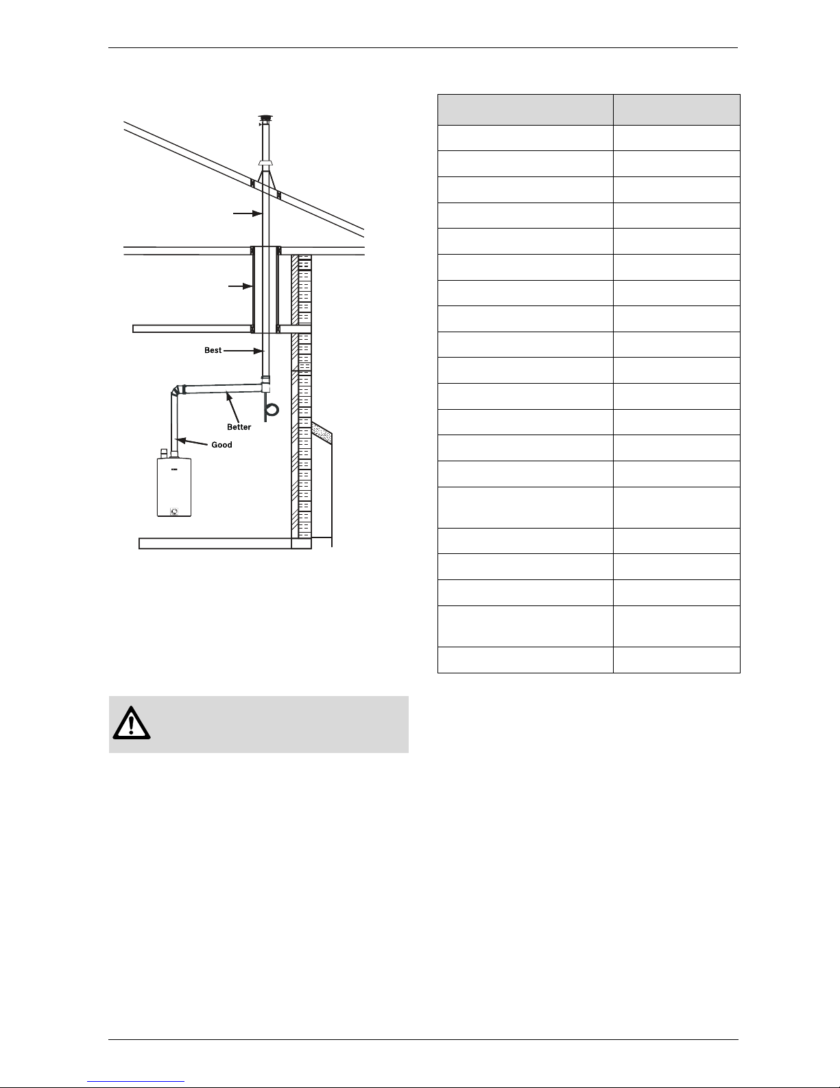
For these solutions to be effective, the internal flapper
must be 100% closed when the water heater is not running. Refer to Fig. 25 and 26 for preferred installation
positions in the vent system.
If using the Zflex damper:
• Ensure directional arrow on damper label faces in the
same direction as exhaust flow.
• If installed horizontally, the axis must be horizontal or
slightly pitched up towards termination to ensure
damper closes 100% when heater is not running.
• To allow accessibility, damper must not be installed
in an enclosed section of vent pipe.
• Do not install damper in unconditioned spaces (e.g.
attics) Condensation can build up while the heater is
running which can later freeze and potentially block
the flapper.
Fig. 25 Combustion air piping not shown for clarity
purposes
Good - Vertical directly on top of the heater.
Better - Closer to the termination horizontally installed in a condi-
tioned space.
Best - Closer to the termination vertically installed in a conditioned
space.
6720608542-07.1V
6720608542-08.1V
6720608542-06.1V
6 720 644 930
Installation instructions
19
Fig. 26 Combustion air piping not shown for clarity
purposes
Good - Vertical directly on top of the heater.
Better - Closer to the termination horizontally installed in a condi-
tioned space.
Best - Closer to the termination vertically installed in a conditioned
space.
3.3.7 Venting for manufactured (mobile) homes
When this appliance is installed in a mobile home, it is
required that the venting be installed such that all combustion air is provided from outside the structure. As
such, single pipe venting installations are forbidden in
mobile home installations. Appropriate flue gas venting
parts are listed in the table 19:
Warning: In a manufactured (mobile)
home installation, combustion air shall
not be supplied from occupied spaces.
Preferred damper position for vertical terminations
Unconditioned
space. Do not
install damper.
Enclosed vent
pipe. Do not
install damper.
6720608542-09.1V
3" Venting Z-flex Venting
24" Drain Tube Kit 2SVEDTK24
3" x 45° Elbow 2SVEEWCF0345
3" x 90° Elbow 2SVEEWCF0390
3" x 6" Pipe 2SVEPWCF03.5
3" x 12" Pipe 2SVEPWCF0301
3" x 18" Pipe 2SVEPWCF0301.5
3" x 2' Pipe 2SVEPWCF0302
3" x 3' Pipe 2SVEPWCF0303
3" x 4' Pipe 2SVEPWCF0304
Inline Vertical Tee 2SVEVDP03
3" Roof Flashing 0/12-6/12 2SVSADJF03
3" Roof Flashing 7/12-12/12 2SVSADJSF03
3" Rain Cap 2SVSRCF03
3" Custom Wall Thimble 2SVSWTCEC03
3" Exhaust/Intake Vent Hood
w/10" Sleeve (Qty 2)
2SVSTB03
3" Adjustable Adapter 4ZVAL03
3" Gear Clamps (Qty 2) 7HS44XX
3" Storm Collar 2SVSLSF03
Extreme Weather Termination*
2SVSHRC03
Horizontal Drain Tee 2SVEDWCF03
Table 19 Z-Flex Venting list
6 720 644 930
20
Installation instructions
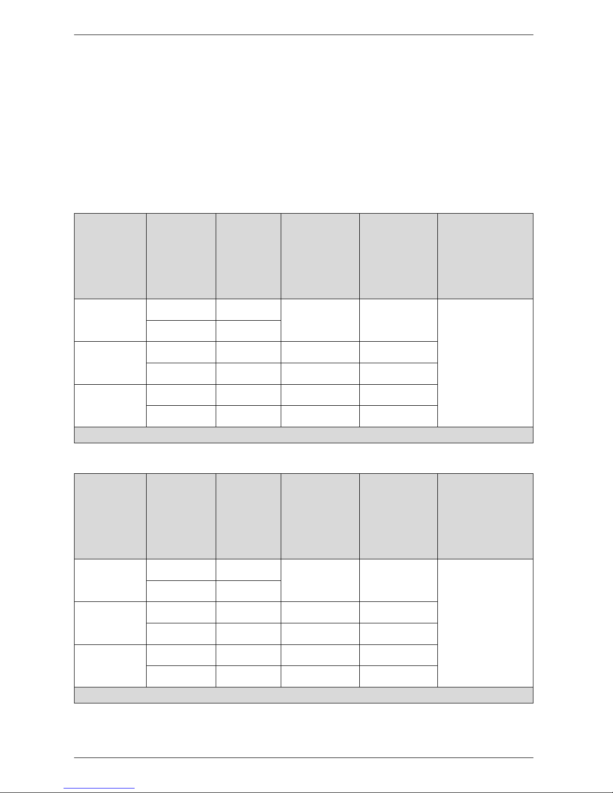
3.3.8 Fan speed adjustment
IMPORTANT! Installation adjustment:
After installing the water heater, the fan speed values for minimum power (P2) and maximum power (P1) may need
adjustment due to variations in altitude and vent pipe length.
Failure to make necessary adjustments to fan speed values may result in improper operation of the appliance.
First calculate the total equivalent vent length. This is the straight pipe length of both exhaust and combustion air plus
the number of elbows used. To determine the length equivalency of each elbow refer to table 6.
Use the equivalent vent length value to determine the appropriate fan speed values found in Table 20 and 21. Refer
to page 21 on how to adjust the fan speeds if an adjustment is necessary. After changing fan speed values, proceed
to section 6.4 to confirm CO2 values are within specified ranges.
Fan speed adjustment
Natural Gas Liquid propane
Altitude
(above sea
level)
Total
equivalent
vent length
1)
1) Full equivalent length (inlet + outlet piping + fittings)
Minimum
power fan
speed (P2)
Maximum
power fan speed
(P1)
Maximum
power fan speed
(P1)
0 - 2000 ft
(0 - 610 m)
3.5 - 32 ft
7
No
modification required
No
modification required
For operation at elevations
above 2,000 ft (610 m) the
equipment ratings shall be
reduced at the rate of 4% for
each 1,000 ft (305 m) above sea
level
33 - 57 ft
8
2000 - 4500 ft
(610 - 1372 m)
3.5 - 32 ft 8* 54* 47*
33 - 57 ft 8* 55* 48*
4500 - 8000 ft
(1372 - 2439 m)
3.5 - 32 ft 9* 55*
48*
33 - 57 ft 9* 55* 49*
* Above 2000 ft, CO2 levels must be checked with a combustion gas analyzer, see section 6.4 for instructions.
Table 20 Fan speed adjustment for 3" piping
Natural Gas Liquid propane
Altitude
(above sea
level)
Total
equivalent
vent length
1)
1) Full equivalent length (inlet + outlet piping + fittings)
Minimum
power fan
speed (P2)
Maximum
power fan speed
(P1)
Maximum
power fan speed
(P1)
0 - 2000 ft
(0 - 610 m)
2.25 - 59 ft
7
No
modification required
No
modification required
For operation at elevations
above 2,000 ft (610 m) the
equipment ratings shall be
reduced at the rate of 4% for
each 1,000 ft (305 m) above sea
level
60 - 122.5 ft
8
2000 - 4500 ft
(610 - 1372 m)
2.25 - 59 ft 8* 54* 47*
60 - 122.5 ft 8* 55* 48*
4500 - 8000 ft
(1372 - 2439 m)
2.25 - 59 ft 9* 55*
48*
60 - 122.5 ft 9* 55* 49*
* Above 2000 ft, CO2 levels must be checked with a combustion gas analyzer, see section 6.4 for instructions.
Table 21 Fan speed adjustment for 4" piping
 Loading...