

Bosch 8981 021 140 Assembly Manual
Ergonomic Workstations
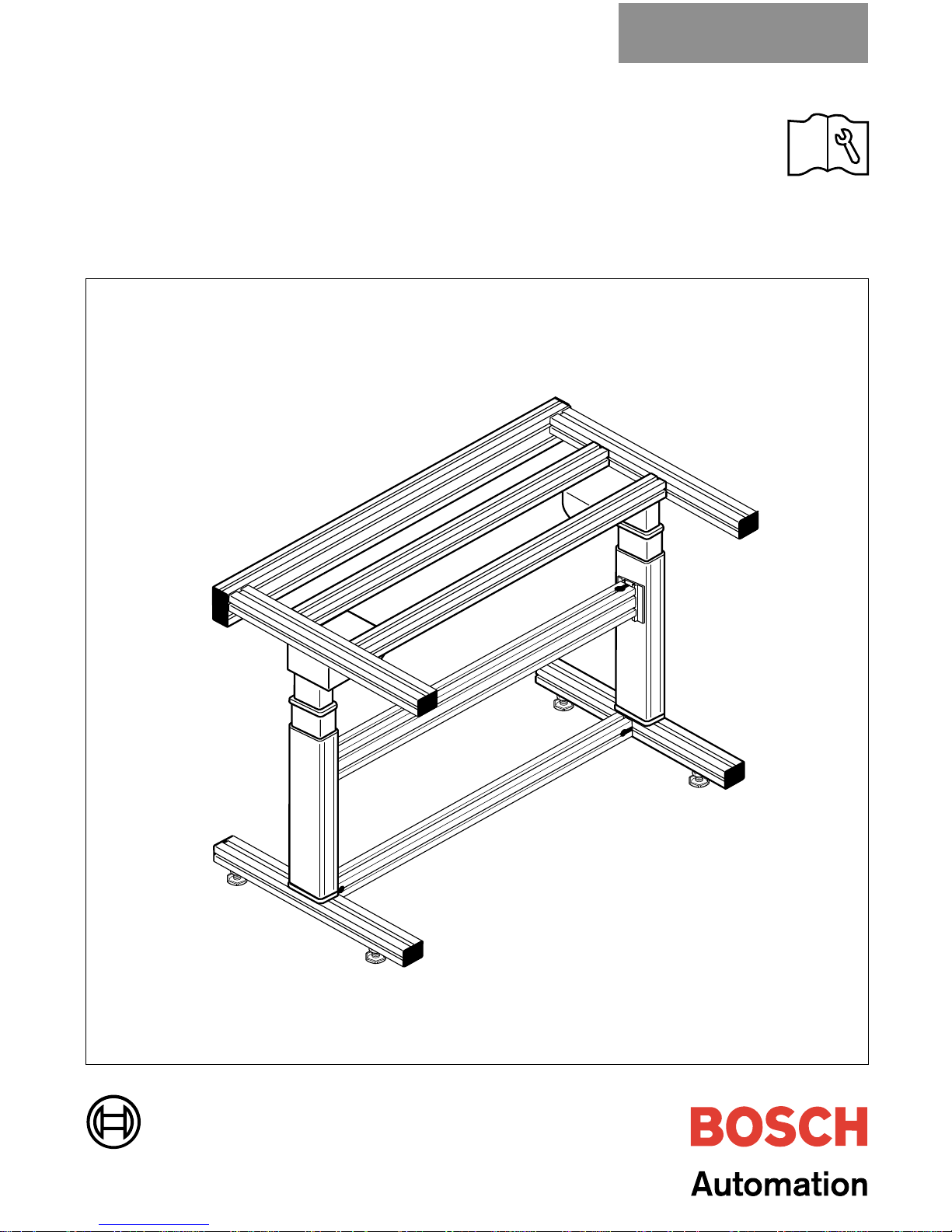
Adjustable Height Workstation Kit
Assembly Guide
Installation and Maintenance
Publication Number: 8981 500 300 7/02
Adjustable Height Workstation

2
Table of Contents
Important Safety Information ........................................................................................................................................3
About This Manual ..........................................................................................................................................................5
Technical Data .................................................................................................................................................................6
Application and Function...............................................................................................................................................6
Recommended Tools .....................................................................................................................................................7
Design and Detailed Description ................................................................................................................................8
Parts List............................................................................................................................................................................8
Before You Begin......................................................................................................................................................... 10
Table Top Assembly ....................................................................................................................................................11
Using T-bolts and T-nuts ............................................................................................................................................13
Joining Profiles ..............................................................................................................................................................13
Attaching the Cross Braces ......................................................................................................................................14
Attaching the Table Top ............................................................................................................................................. 15
Control Box Mounting .................................................................................................................................................16
Installing the Cross Brace..........................................................................................................................................17
Mounting Telescoping Acturator Assembly........................................................................................................... 18
Assembling the Base Frame...................................................................................................................................... 20
Mounting Base Frame to the Telescoping Acturators ........................................................................................ 21
Final Assembly ..............................................................................................................................................................22
Operation and Maintenance ...................................................................................................................................... 23
Warranty Information ................................................................................................................................................... 24
Liability ............................................................................................................................................................................24
Environmental Protection ...........................................................................................................................................24
All rights are held by BOSCH REXROTH CORPORATION and
ROBERT BOSCH GMBH, also regarding patent claims. We retain
all powers of disposition, such as for copying and/or for passing-on to
third parties.
We reserve the right to make technical changes at any time
without notice.
Errors and omissions excepted.
© 2002 Bosch Rexroth Corporation
IMPORTANT SAFETY INFORMATION
IMPORTANT: This assembly and operation manual should be reviewed
with all equipment operators as part of your operator training program.
3
SAFETY FIRST!
Important safety information is contained throughout
this manual to alert you to potentially dangerous
situations and help prevent accidental injury and
property damage.
The safety warning symbol above has been included
to warn you of hazards that can hurt or kill you and
others, and/or cause serious damage to the equipment
and other property.
In addition, the following safety alert words are used:
DANGER! Means that you or others will
be seriously or fatally injured if
instructions are not followed.
WARNING! Means that you or others may
be seriously or fatally injured if
instructions are not followed.
Material Hazards:
Some components, such as gearboxes, contain
lubricants or other materials that can represent a
potential health hazard if handled, stored, or disposed
of improperly.
Please contact Bosch for copies of the Material
Safety Data Sheets (MSDS) for the lubricating oil
used in gearboxes and other potentially hazardous
materials.
Review All Safety Information:
Please review the safety information included on
page 4 and throughout this manual with all installers,
operators, and maintenance personnel of this
equipment.
CAUTION! Means that you or others may
be injured if instructions are
not followed.
4
IMPORTANT SAFETY INFORMATION
WARNING!
Please read all assembly, and maintenance instructions
carefully before beginning set-up of the components in
this document.
Where appropriate, warning symbols have been
included in this publication to alert you of potential or
impending danger.
• Be sure to read and observe all safety warnings in
this document as well as those attached to the
individual modules. Failure to do so could result in
potential risks to your health and safety as well as
those around you.
• Covers and guards have been designed to
eliminate pinch points and exposure to moving
components. DO NOT operate the adjustable
height workstation or any machinery with the
guards removed. Serious injury may result!
• All set-up maintenance and repair work should
be performed only by properly trained, qualified
personnel. All operators must be properly trained
in the use of this equipment.
holders, balancers, lights, parts bins and power
strips. Maximum workstation load must not exceed
400 lb (181.5 kg), either centered or distributed.
Exceeding published specifications will result in
premature wear, damage, or failure of the motor,
gearbox, seals and/or other components.
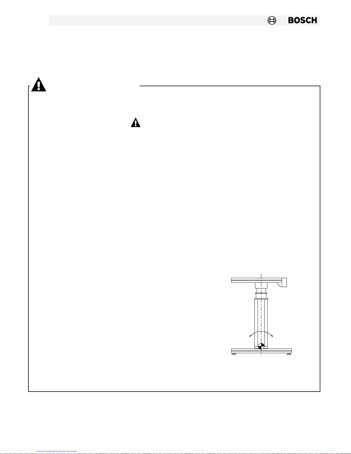
• CAUTION–Tip over hazard! Extension arms with
tool holders and parts bins can present a potential
tip over hazard under certain height and load
conditions. Table tops with overhangs also present
a potential for tip over. Be sure the load is always
centered on the table top. If it is not possible to
center the load, be sure it is evenly distributed
from side to side and front to back. DO NOT sit,
stand or lean on table tops! DO NOT exceed the
maximum allowable moment of 500 Nm as shown
in the diagram below! For maximum stability and
safety Bosch Rexroth recommends anchoring the
workstation to the floor. A number of floor
anchoring options can be found in the Bosch
aluminium structural framing catalog available
through your local distributor.
• Be sure to follow all local, state and federal
regulations when installing electrical devices of
any type
• Unplug the workstation before beginning
maintenance or repair work of any type on the
adjustable height workstation.
• The adjustable height workstation is designed to be
used in assembly operations where ergonomic
considerations dictate the need for a height
adjustable workstation. Table top maximum width is
1400 mm. The minimum width is 1000 mm.
It will accommodate extension arms for tool
SAVE THESE INSTRUCTIONS!
Allowable Moment=
500 Nm Maximum

About this manual
5
The manual is divided into the following sections to
make it easier to use:
• Technical Data – Provides the most important
technical specifications.
• Application and Function – Gives general
information about the Adjustable Height
Workstation.
• Design and Detailed Description – Supplies an
overview of the modules that make up the
Adjustable Height Workstation. This section will
familiarize you with the modules individual
components.
• Assembly – Lists step-by-step assembly
instructions for the Adjustable Height Workstation.
• Operation – provides valuable operating
information.
• Maintenance – None required over life of unit.
If this module was ordered as CE compliant, please
contact our applications engineering department for
a copy of the latest manufacturer's CE declaration, if
required for your records.
6
Technical Data
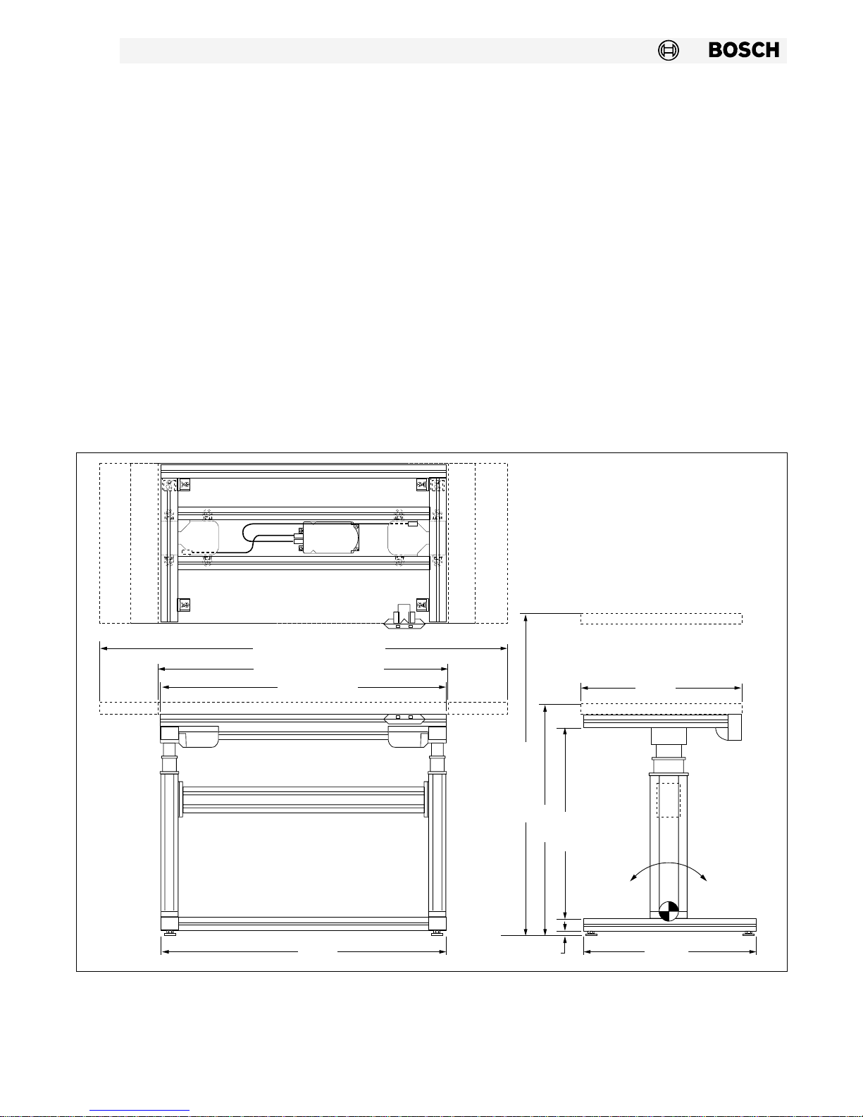
Functional dimensions for the Adjustable Height Table
Frame Kit are shown in Figure 1 below.
The minimum height is nominal since the position of
the height adjustment studs and thickness of the table
top will effect this dimension.
The table frame is constructed of 6063 T6 aluminum
profile. It is clear anodized to give a professional
finished appearance.
The Adjustable Height Table Frame Kit is powered by
two 110 VAC, 60 Hz motors. The telescoping actuators
have a maximum adjustment range of 500 mm, and will
support a maximum load of 400 lb (181.5 kg).
Application and Function
The Adjustable Height Table Frame Kit is used in
assembly operations where ergonomic considerations
dictate the need for height adjustability.
Height adjustment is accomplished with simple pushbutton up/down control supplied with the unit. 110
VAC motors inside the telescoping actuators supply
the power for the height adjustment. The two motors
are synchronized electronically by a control module
also supplied with the unit.
Figure 1
Table Top Max. 1400mm
Table Top Min. 1000mm
Frame 990mm
595mm
Max. 1302mm
15mm
802mm
640mm
555mm
500 Nm
Maximum
Moment
595mm
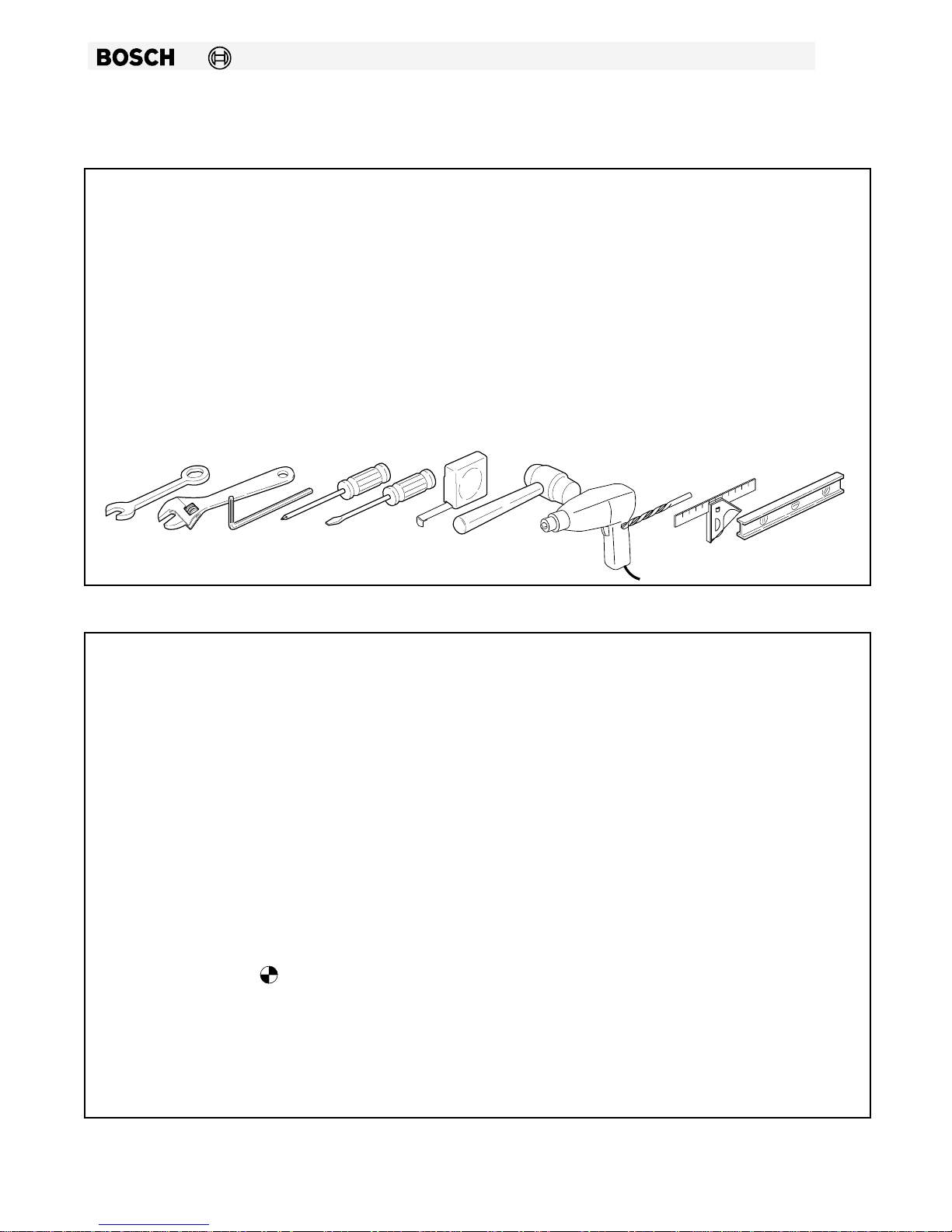
Recommended Tools
The following tools are recommended to assemble the Adjustable Height Table Frame Kit:
7
1 13 mm and 19 mm combination wrench
1 5, 6, 8, and 10 mm allen wrenchs
1 flat tip screwdriver
1 electric drill
1 soft faced mallet
1 adjustable wrench
1 #1 and #2 phillips screwdriver
1 tape measure
1 square
1 2 mm and 3 mm drill bits for drilling pilot holes
in the table top.
1 level
Specifications
Adjustable Height Workstation Kit Part Number........................................................................... 8981 021 140
Frame Height.................................................................................................................. 802 – 1302 mm Adjustable
Frame Width................................................................................................................................. 990 mm (38.976 in)
Table Top Width.....................................................................................................1000 mm min. – 1400 mm max.
Frame Depth................................................................................................................................. 595 mm (23.425 in)
Maximum Load, Centered .............................................................................................................. 400 lb (181.5 kg)
Maximum Load, Distributed ........................................................................................................... 400 lb (181.5 kg)
Maximum Moment @
Shipping Weight W/Out Table Top:
Carton 1 – Telescoping Actuators and Components ...........................................................40.5 lb (18.4 kg)
Carton 2 – Frame Components..................................................................................................45.5 lb (20.7 kg)
....................................................................................................................500 Nm (Static)

8
Design and Detailed Description
The Adjustable Height Table Frame Kit contains all of
the components necessary to build an electric lift
height adjustable table frame. The lift mechanism
consist of two motors synchronized with an electrotonic
control. The frame components are made from extruded
aluminum profiles. Tabletops are sold separately and
include 4 mounting screws and flatwashers.
Parts List
Item No. Qty. Part Number Description
1 2 8981 992 026/870 Profile, 45x45 –/–
2 1 3842 990 644/867 Profile, 45x45 D17/D17
3 2 8981 021 266 Profile, 45x60 W/S12x30 screws
4 2 8981 021 148 Profile W/Inserts, P45x60H
5 1 8981 021 147 Profile, 45x90H D17/D17 SPCL
6 1 8981 021 145 Profile, 45x90L D9.5/D9.5 SPCL
7 2 8981 021 127 Telescoping Actuator (TMA) with 8–Hex Nuts
8 2 8981 021 129 Plate, Mounting
9 2 3842 500 923 Bolt Connector Kit, 90 mm
10 2 3842 500 921 Bolt Connector Kit, 45 mm
11 16 3842 197 091 T-bolt
12 16 3842 345 081 M8 Flange Nut
13 8 3842 242 493 T-Nut, 10mm, M8
14 16 2910 131 238 Screw, DIN 7984-M8x16-8.8-CZ
15 4 3842 513 560 Economy Leveling Stud, M12
16 2 2915 051 119 Nut, ISO4036-M-12
17 4 3842 502 387 WS58N12 Washer, Lock (Zinc)
18 4 2910 141 350 Screw, DIN 912-M12x50-8.8-CZ
19 8 2910 141 207 Screw, DIN 912-M6x35-8.8-CZ
20 8 3842 502 384 WS58N6 Washer, Lock (Zinc)
21 4 2910 611 014 3.5x22-CH-CA screw (DIN7981-ST)
22 4 8981 021 193 Rectangular Nut
23 8 3842 523 537 Plastic Adapter, 8mm to 10mm
24 8 3842 515 473 Adjustable Angle Gusset
25 10 3842 523 558 Gusset, 45x45
26 6 3842 523 563 Round Cover Cap, 45x45
27 6 3842 515 122 End Cap, 45x60 H Black
28 2 3842 511 783 End Cap, 45x90 H Black
29 1 8981 021 190 Control Box
30 1 8981 021 192 Switch W/Mounting Bracket
31 4 3842 506 739 Cable Carrier, 10mm
Not shown 4 8981 010 500 Cable Tie, Black 8.0 x 0.1 in
Not Shown 2 8981 021 191 Cable
Not Shown 1 8981 500 290 Layout Template
 Loading...