

Bosch 830 ES, 940 ES User Manual
Temperature Modulated with Electronic Ignition Suitable for heating potable water and space heating
(Intended for variable flow applications)
INDOOR MODEL
830 ES
Warning: If the information in this manual is not followed exactly, a fire
or explosion may result causing property damage, personal injury or
death.
Do not store or use gasoline or other flammable vapors and liquids in the
vicinity of this or any other appliance.
Installation and service must be performed by a trained and certified
installer, service agency or the gas supplier.
Improper installation, adjustment, alteration, service or maintenance
can cause injury or property damage. Refer to this manual. For assistance or additional information consult a qualified installer, service
agency or the gas supplier.
In the Commonwealth of Massachusetts this product must be installed
by a licensed plumber or gas fitter.
Upon completion of the installation, these instructions should be
handed to the user of the appliance for future reference.
What to do if you smell gas
•
Turn off the gas shut-off valve. Open windows and doors.
• Do not try to light any appliance.
• Do not touch any electrical switch, telephone, and do not use outlets.
• Extinguish all open flames. Do not smoke! Do not use lighters!
• Warn all occupants of the building. Do not ring doorbells!
• If you can hear gas leaking, leave the building immediately. Prevent
others from entering the building and notify the police and fire
department from outside the building.
• From outside the building, call the gas utility company and a trained
and certified installer.
830 ES - Natural Gas / 830 ES - Liquefied Petroleum (LP) Gas
6 720 644 936 (2013/01) US

2 | Table of contents
830 ES6 720 644 936 (2013/01)
Table of contents
1 Key to symbols and safety instructions . . . . . . . . . . . . . . . . . . . 3
1.1 Key to symbols . . . . . . . . . . . . . . . . . . . . . . . . . . . . . . . . . 3
1.2 Safety instructions . . . . . . . . . . . . . . . . . . . . . . . . . . . . . . 3
2 FCC rules . . . . . . . . . . . . . . . . . . . . . . . . . . . . . . . . . . . . . . . . . . . . . 6
3 Appliance details . . . . . . . . . . . . . . . . . . . . . . . . . . . . . . . . . . . . . . 6
3.1 Features . . . . . . . . . . . . . . . . . . . . . . . . . . . . . . . . . . . . . . . 6
3.2 Specifications (Technical data) . . . . . . . . . . . . . . . . . . . . 7
3.3 Unpacking the heater . . . . . . . . . . . . . . . . . . . . . . . . . . . . 7
3.4 General rules to follow for safe operation . . . . . . . . . . . . 8
3.5 Dimensions and minimum installation clearances . . . . . 9
4 Installation instructions . . . . . . . . . . . . . . . . . . . . . . . . . . . . . . 10
4.1 Specialized tools . . . . . . . . . . . . . . . . . . . . . . . . . . . . . . 10
4.2 Introduction . . . . . . . . . . . . . . . . . . . . . . . . . . . . . . . . . . 10
4.3 Venting . . . . . . . . . . . . . . . . . . . . . . . . . . . . . . . . . . . . . 10
4.4 Combustion air requirements . . . . . . . . . . . . . . . . . . . . 23
4.5 Proper location for installing your heater . . . . . . . . . . 23
4.6 Heater placement and clearances . . . . . . . . . . . . . . . . 24
4.7 Hanging appliance on the wall . . . . . . . . . . . . . . . . . . . 24
4.8 Mounting installation for manufactured
(mobile) homes . . . . . . . . . . . . . . . . . . . . . . . . . . . . . . . 25
4.9 Gas piping & connections . . . . . . . . . . . . . . . . . . . . . . 26
4.10 Water connections . . . . . . . . . . . . . . . . . . . . . . . . . . . . 28
4.11 Water quality . . . . . . . . . . . . . . . . . . . . . . . . . . . . . . . . . 28
4.12 Domestic hot water recirculation . . . . . . . . . . . . . . . . . 29
4.13 Space heating applications . . . . . . . . . . . . . . . . . . . . . . 29
4.14 Measuring gas pressure . . . . . . . . . . . . . . . . . . . . . . . . 31
5 Electrical connections . . . . . . . . . . . . . . . . . . . . . . . . . . . . . . . 31
5.1 Electrical power supply . . . . . . . . . . . . . . . . . . . . . . . . . 31
5.2 Position of the fuses in control unit . . . . . . . . . . . . . . . 32
6 Operation instructions . . . . . . . . . . . . . . . . . . . . . . . . . . . . . . . 32
6.1 Description LCD Display . . . . . . . . . . . . . . . . . . . . . . . . 32
6.2 For your safety read before operating
your water heater . . . . . . . . . . . . . . . . . . . . . . . . . . . . . . 33
6.3 Power . . . . . . . . . . . . . . . . . . . . . . . . . . . . . . . . . . . . . . . 33
6.4 Temperature selection . . . . . . . . . . . . . . . . . . . . . . . . . 33
6.5 Use of optional remote control accessory
(part no. TSTAT2) . . . . . . . . . . . . . . . . . . . . . . . . . . . . . . 34
6.6 Operation . . . . . . . . . . . . . . . . . . . . . . . . . . . . . . . . . . . . 35
6.7 Reset button . . . . . . . . . . . . . . . . . . . . . . . . . . . . . . . . . 35
6.8 Program button . . . . . . . . . . . . . . . . . . . . . . . . . . . . . . . 35
6.9 Locked condition . . . . . . . . . . . . . . . . . . . . . . . . . . . . . . 35
7 Maintenance and service . . . . . . . . . . . . . . . . . . . . . . . . . . . . . . 35
7.1 Annual maintenance . . . . . . . . . . . . . . . . . . . . . . . . . . . . 35
7.2 Winterizing for seasonal use . . . . . . . . . . . . . . . . . . . . . . 36
7.3 Mineral scale build-up . . . . . . . . . . . . . . . . . . . . . . . . . . . 36
7.4 Adjusting CO2 . . . . . . . . . . . . . . . . . . . . . . . . . . . . . . . . . 36
7.5 Program values . . . . . . . . . . . . . . . . . . . . . . . . . . . . . . . . 38
7.6 Control board diagnostics . . . . . . . . . . . . . . . . . . . . . . . 38
8 Troubleshooting . . . . . . . . . . . . . . . . . . . . . . . . . . . . . . . . . . . . . 40
8.1 Introduction . . . . . . . . . . . . . . . . . . . . . . . . . . . . . . . . . . . 40
8.2 Burner does not ignite when hot water is turned ON . . 40
8.3 Water is too hot . . . . . . . . . . . . . . . . . . . . . . . . . . . . . . . . 40
8.4 Water is not hot enough . . . . . . . . . . . . . . . . . . . . . . . . . 40
8.5 Low water flow/pressure . . . . . . . . . . . . . . . . . . . . . . . . 40
8.6 Hot water temperature fluctuates at tap . . . . . . . . . . . . 41
8.7 Noisy burner/heater during operation . . . . . . . . . . . . . . 41
9 Problem solving . . . . . . . . . . . . . . . . . . . . . . . . . . . . . . . . . . . . . . 42
9.1 Error code diagnostics . . . . . . . . . . . . . . . . . . . . . . . . . . 42
10 Electrical diagram . . . . . . . . . . . . . . . . . . . . . . . . . . . . . . . . . . . . 45
11 Sensor resistance charts . . . . . . . . . . . . . . . . . . . . . . . . . . . . . . 46
12 Functional scheme . . . . . . . . . . . . . . . . . . . . . . . . . . . . . . . . . . . 47
13 Interior components diagram and parts list . . . . . . . . . . . . . . 48
13.1 Interior components . . . . . . . . . . . . . . . . . . . . . . . . . . . . 48
13.2 Components diagram . . . . . . . . . . . . . . . . . . . . . . . . . . . 50
14 Protecting the environment . . . . . . . . . . . . . . . . . . . . . . . . . . . 56
15 LIMITED WARRANTY FOR BOSCH THERM AND GREENTHERM
TANKLESS WATER HEATERS . . . . . . . . . . . . . . . . . . . . . . . . . . 57
16 Installer Checklist to be completed by installer upon
installation . . . . . . . . . . . . . . . . . . . . . . . . . . . . . . . . . . . . . . . . . 58
Key to symbols and safety instructions | 3
6 720 644 936 (2013/01)830 ES
1 Key to symbols and safety instructions
1.1 Key to symbols
Warnings
The following keywords are defined and can be used in this document:
• NOTICE indicates that damage to property may occur.
• CAUTION indicates that personal injury may occur.
• WARNING indicates that severe personal injury may occur.
• DANGER indicates that severe personal injury or death may occur.
Important information
Additional symbols
1.2 Safety instructions
Read all instructions before installing. Perform the steps in the indicated
sequence. Have the water heater inspected by a trained service
technician at least once every year. Failure to comply with these
instructions can result in severe, possibly fatal, personal injury as well as
damage to property and equipment.
Installation and servicing
▶ Risk of fire when soldering and brazing!
Take appropriate protective measures when soldering and brazing
around combustible and flammable material.
▶ Ensure that only a licensed contractor installs or services the water
heater.
▶ On hot components use only material with adequate temperature
stability.
Installation and commissioning
▶ In the Commonwealth of Massachusetts, the water heater must be
installed by a licensed plumber.
▶ Do not install this device in rooms with a high moisture level
(e.g. bathrooms, saunas).
Function
▶ To ensure that the water heater functions properly, follow these
installation and maintenance instructions.
▶ Never close the blow-off line of the T&P safety valve. For safety
reasons, water may escape during heating.
If you smell gas
▶ Turn off the gas shut-off valve.
▶ Open windows and doors.
▶ Do not try to light the appliance.
▶ Do not touch any electrical switch, telephone, and do not use outlets.
▶ Extinguish all open flames. Do not smoke! Do not use lighters!
▶ Warn all occupants of the building. Do not ring doorbells!
▶ If you can hear gas leaking, leave the building immediately.
▶ Prevent others from entering the building and notify the police and
fire department from outside the building.
▶ From outside the building, call the gas utility company and a trained
and certified installer.
If you smell flue gas
▶ Switch off the appliance.
▶ Open windows and doors.
▶ Inform a trained and certified installer.
Insufficient ventilation may cause toxic flue gas to escape. Risk of
poisoning.
▶ Never close off or reduce the size of the air intake and outlet openings.
▶ The appliance must not be operated until any obstructions have been
removed.
▶ Inform the system operator in writing of the problem and the
associated dangers.
Danger from escaping flue gases
▶ Ensure all vent pipes and chimneys are not damaged or blocked.
▶ Connect only one appliance to each vent system or chimney liner.
▶ The venting system piping must not feed into another air extraction
duct.
▶ Do not route the flue system piping through or inside another air
extraction duct.
Danger of explosion of flammable gases
▶ Work on gas components may only be carried out by a trained and
certified installer.
▶ Installation, gas and flue connection, initial commissioning, electrical
connections and annual maintenance must only be carried out by a
trained and certified installer.
Combustion air
▶ Keep the combustion air free of corrosive substances (halogenated
hydrocarbons that contain chlorine or fluorine compounds).
Never shut off safety valves!
▶ Water may escape from the safety valve at any time when the water is
being heated.
Inspection/maintenance
▶ Servicing and repairs may only be carried out by a trained and
certified installer.
▶ Immediately correct all faults to prevent system damage.
▶ Use only Bosch spare parts! Damage caused by the use of parts not
supplied by Bosch may void the warranty.
Instruct the customer
▶ Explain to the customer how the appliance works and how to operate
it.
▶ Inform the customer that he/she must not carry out any alterations or
repairs.
Warnings in this document are identified by a warning
triangle printed against a grey background.
Keywords at the start of a warning indicate the type and
seriousness of the ensuing risk if measures to prevent
the risk are not taken.
Important information in cases where there is no risk of
personal injury or material losses is identified by the
symbol shown on the left. It is bordered by horizontal
lines above and below the text.
Symbol Explanation
▶ Step in an action sequence
Cross-reference to another part of the document
• List entry
– List entry (second level)
Table 1

4 | Key to symbols and safety instructions
830 ES6 720 644 936 (2013/01)
Danger from electric shock
▶ Ensure that only an authorized contractor performs electrical work.
▶ Before performing electrical work, disconnect the power and secure
the unit against unintentional reconnection.
▶ Ensure the system has been disconnected from the power supply.
Risk of scalding at the hot water draw-off point
▶ When the water heater is in operation, temperatures in excess of
122 °F (50 °C) can occur. To limit the temperature at the tap, install a
thermostatic DHW mixing valve.
▶ Water heated for washing the laundry, dishes and for other cleaning
purposes can cause scalding and permanent injuries.
▶ Children, elderly, and handicapped persons are more likely to be
permanently injured by hot water. Never leave such individuals in the
tub or shower unattended under any circumstances. Children must
not be allowed to operate hot water faucets themselves or to fill a
bathtub.
▶ If the building has occupants in the above groups who operate hot
water faucets, or state laws / local ordinances stipulate specific water
temperatures, take the following precautions:
– Use the lowest possible temperature setting.
– To prevent scalding, install a tempering device, such as an
automatic mixing valve, at hot water tap or water heater. Select and
install the automatic mixing valve in accordance with the valve
manufacturer's recommendations and instructions.
▶ Water exiting from drain valves can be extremely hot. To avoid
injuries:
– Check that all connections are tight.
– Direct exiting water away from people.
▶ Measures must be taken to protect against excessive temperature and
pressure! Installation of a T&P safety valve is required.
To protect against corrosion and ensure compliance with the rules for
electrical safety, observe the following points:
▶ Use metal fittings for potable water heating systems with plastic
piping.
▶ Use only original accessories from the manufacturer.
▶ When installation of the water heater is complete, inspect the ground
conductor (including metal fittings).
Maintenance
Customers are advised to:
▶ Sign a maintenance and inspection contract with an authorized
contractor. Inspect and maintain the water heater as necessary and
on a yearly basis. Service as needed.
▶ Use only genuine spare parts.
Flooding
▶ After a flood, do not use the appliance if any part has been
submerged. Damage to appliances that have been submerged can be
quite severe and pose numerous safety risks.
▶ Every appliance that has been submerged must be replaced.
Key to symbols and safety instructions | 5
6 720 644 936 (2013/01)830 ES
For your safety
▶ Do not store or use gasoline or other flammable, combustible or
corrosive vapors and liquids in the vicinity of this or any other
appliance.
DANGER: Fatal accidents!
Carbon monoxide poisoning.
▶ Carefully plan where you install the heater. Correct
combustion air supply and flue pipe installation are
very important. If a gas appliance is not installed
correctly, fatal accidents can result such as carbon
monoxide poisoning or fire.
DANGER:
Carbon monoxide poisoning.
▶ Exhaust gas must be vented to outside using
approved vent material. See table 8, page 11 (In
Canada use only ULCS636 approved material). Vent
and combustion air connector piping must be sealed
gas-tight to prevent flue gas spillage, carbon
monoxide emissions and risk of fire, resulting in
severe personal injury or death. Approved vent
terminations must be used when penetrating to the
outside.
DANGER: Electric shock!
▶ Field wiring connections and electrical grounding
must comply with local codes, or in the absence of
local codes, with the latest edition of the National
Electric Code, ANSI/NFPA 70, or in Canada, all
electrical wiring must comply with the local codes and
the Canadian Electrical Code, CSA C22.1 Part 1.
DANGER: Electric shock!
Shock hazard: line voltage is present.
▶ Before servicing the water heater, unplug power
supply cord from outlet. Failure to do so could result
in severe personal injury or death.
WARNING: Damage to the appliance from over
pressure.
▶ The heater must be disconnected from the gas supply
piping system during any pressure testing of that
system at test pressures equal to or more than 0.5
psi.
NOTICE:
▶ The appliance should be located in an area where
leakage of the heater or connections will not result in
damage to the area adjacent to the appliance or to
lower floors of the structure. When such locations
cannot be avoided, it is recommended that a suitable
drain pan, adequately drained, be installed under the
appliance. The pan must not restrict combustion air
flow.
WARNING:
▶ The maximum inlet gas pressure must not exceed the
value specified by the manufacturer and the minimum
value listed is for the purpose of input adjustment.
NOTICE:
▶ If a water heater is installed in a closed water supply
system, such as one having a backflow preventer in
the cold water supply line, means shall be provided to
control thermal expansion. Contact the water
supplier or local plumbing inspector on how to control
this situation.
WARNING: Fire danger!
▶ Keep appliance area clear and free from combustible
materials, gasoline and other flammable vapors and
liquids.
NOTICE:
▶ Do not obstruct the flow of combustion and
ventilation air.
NOTICE: Appliance malfunction!
▶ If power is lost while appliance is operating. Turn off
both water and power for 15 seconds to reset device.
WARNING: Risk of scalding and property damage.
▶ Precautions must be taken prior to manually
operating the relief valve to avoid contact with hot
water discharged from the relief valve and to prevent
water damage.
NOTICE: Appliance damage!
▶ Label all wires prior to disconnection when servicing
controls. Wiring errors can result in improper and
dangerous operation. Verify proper operation after
servicing.
WARNING: System damage!
▶ If a relief valve discharges periodically, this may be
due to thermal expansion in a closed water supply
system. Contact the water supplier or local plumbing
inspector on how to correct this situation. Do not plug
the relief valve.
WARNING: Property damage!
▶ If the water heater is used in a space heating
application, all piping and components connected to
the water heater must be suitable for use with potable
water.
WARNING: Personal Injury from toxic chemicals.
▶ Toxic chemicals, such as those used for boiler
treatment, shall not be introduced into the potable
water used for space heating.
WARNING: Personal Injury from toxic chemicals.
▶ A water heater which will be used to supply potable
water shall not be connected to any heating system or
component(s) previously used with a nonpotable
water heating appliance.
6 | FCC rules
830 ES6 720 644 936 (2013/01)
2 FCC rules
FCC: This device complies with Part 15 of the FCC rules. Operation is
subject to the following two conditions: (1) This device may not cause
harmful interference, and (2) this device must accept any interference
received, including interference that may cause undesired operation.
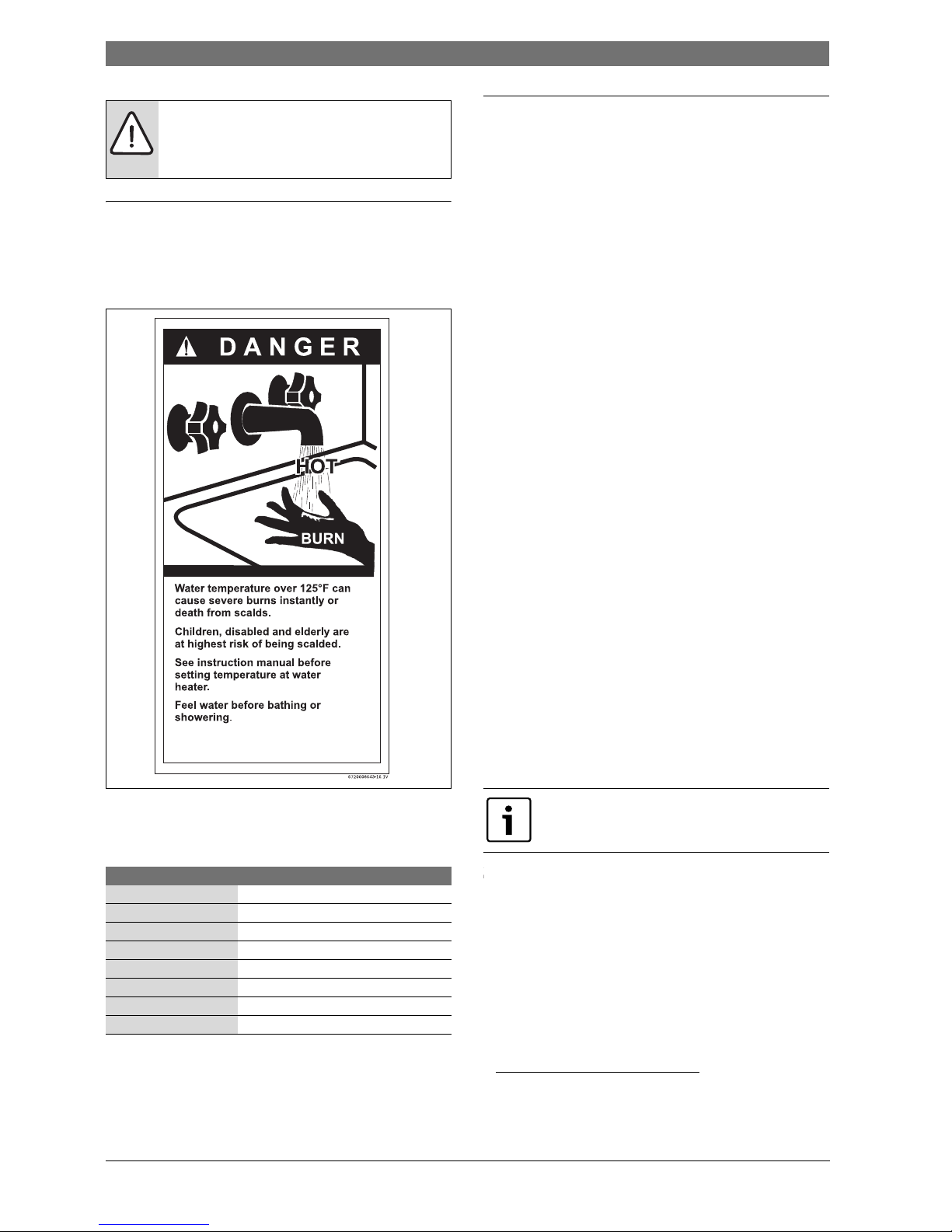
Fig. 1
The chart below shows the relationship between water temperature and
time until there is a risk of scalding. It can be used as the basis for
determining the safest water temperature for your application.
3 Appliance details
3.1 Features
Parts
• Key Pad interface control.
• High power pre-mix compact burner with low NOx emissions.
• Modulating Gas Valve with constant gas:air ratio control.
• Modulating water valve for improved comfort and temperature
control.
High quality materials for long working life
• Copper heat exchanger.
• High efficiency Ceramat Burner.
• Compact space saver: mounts on a wall with a supplied bracket.
Features
• Easily removable one-piece cover.
• On/Off and Temperature control switches.
• Reset button.
• Program button (Selectable temperature default).
• Failure codes for easy diagnostics and repair.
• Real-time diagnostics for troubleshooting/informational purposes.
• Built in freeze prevention.
Note: The freeze prevention kit is designed to provide protection for the
water heater down to approximately 5°F for short term conditions only.
It will not protect the appliance in areas where the temperature is
routinely expected to be below freezing.
- The freeze prevention kit will not protect plumbing outside the
appliance from freezing. Precautions should be taken.
Accessories (Bosch part #)
• Optional wireless remote control to operate with the appliance
(TSTAT2)
• Cascading kit (7 709 003 962)
• Outdoor kit (BTOK)
• Concentric termination kit (196016)
• Exhaust/Intake bird screen (L2594)
• Pipe Cover (PTPCES)
• High temperature kit (7736500074)
• Recess box kit (7736500043)
• Pressure relief valve (7 738 001 152)
• Horizontal vent kit (4TWHVK3SII)
1)
WARNING: Installation in mobile homes.
▶ Installation in mobile homes shall conform to Title 24
CFR, part 3280 and/or CAN/CSA Z240 MH Series,
Mobile Homes.
Temperature Time to severe scalding
1)
1) Source: Moritz, A.R. and Henriques, F.C., Jr. (1947). Studies of thermal injury. II.
The relative importance of time and surface temperature in the causation of
cutaneous burns, Am J of Pathol, 23, 695-720.
120 °F (48 °C) longer than 5 minutes
125 °F (51 °C) 1.5 to 2 minutes
130 °F (54 °C) approx. 30 seconds
135 °F (57 °C) approx. 10 seconds
140 °F (60 °C) less than 5 seconds
145 °F (62 °C) less than 3 seconds
150 °F (65 °C) approx. 1.5 seconds
155 °F (68 °C) approx. 1 second
Table 2 Approximate time-temperature relationship until there is a risk
of scalding
1) 4TWHVK3S vent kit is compatible w ith this appliance but requires the purchase of
an additional 12"
piece of straight pipe to meet minimum vent length
requirements. The aluminum flex piping included with this kit is not permissible
for use with this appliance.
BOSCH is constantly improving its products, therefore
specifications are subject to change without prior
notice.
Appliance details | 7
6 720 644 936 (2013/01)830 ES
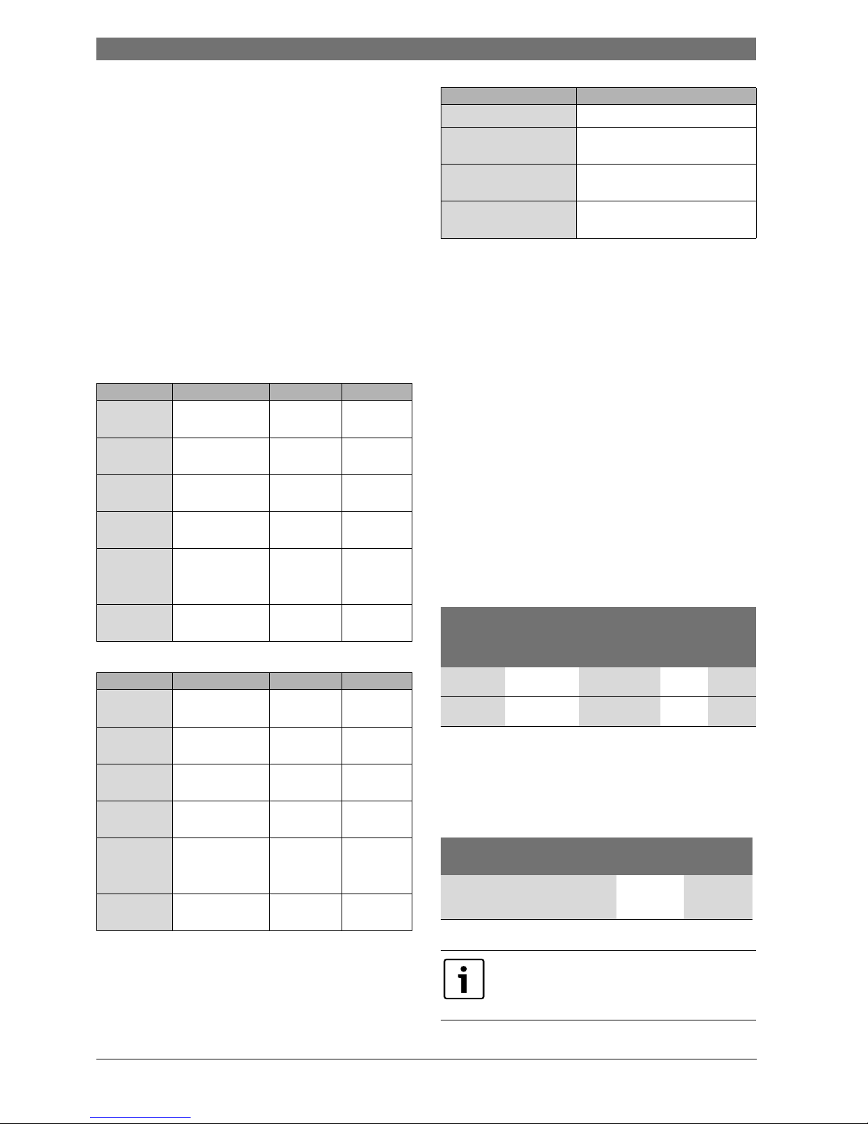
3.2 Specifications (Technical data)
Approved in US/Canada
Safety devices
• Flame failure device (ionization flame rod sensor)
• Overheat prevention (temperature limiter)
• Inlet temperature sensor
• Outlet temperature sensor
• Back flow temperature sensor
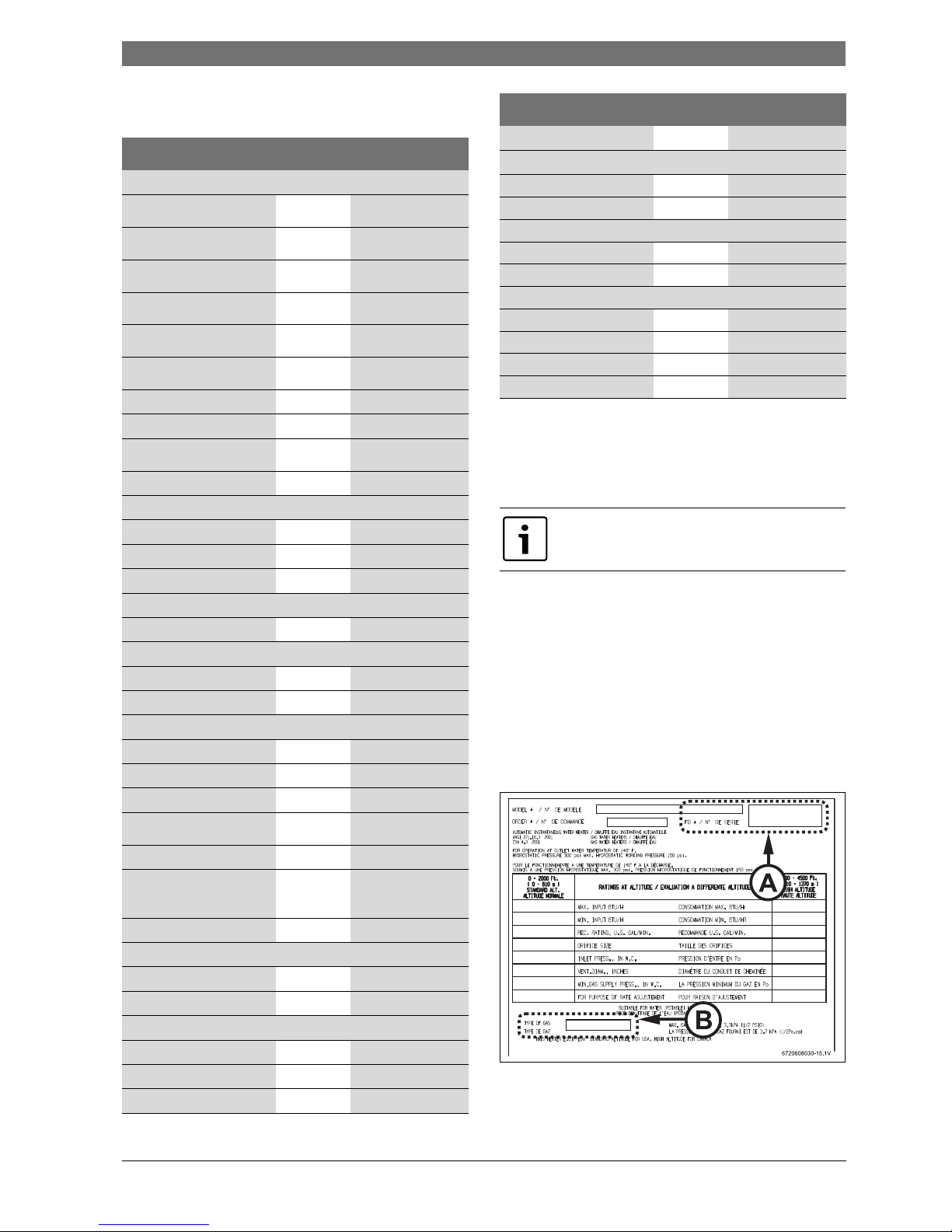
3.3 Unpacking the heater
Before installing the unit, be certain you have the correct heate r for
your type of Gas - Propane or Natural Gas. Identification labels are
found on the shipping box, and on the rating plate which is located on the
right side panel of the cover.
Fig. 2 Rating plate
[A] Serial number
[B] Type of gas
Technical characteristics Units 830 ES
Capacity
Maximum flow rate at a 25 °F
(13.9 °C) rise
GPM (l/min) 11.6 (43.8)
Maximum flow rate at a 35 °F
(19.4 °C) rise
GPM (l/min) 8.3 (31.3)
Maximum flow rate at a 45 °F
(25 °C) rise
GPM (l/min) 6.4 (24.4)
Maximum flow rate at a 55 °F
(30.6 °C) rise
GPM (l/min) 5.3 (19.9)
Maximum flow rate at a 75 °F
(41.7 °C) rise
GPM (l/min) 3.9 (14.6)
Maximum flow rate at a 90 °F
(50 °C) rise
GPM (l/min) 3.2 (12.2)
Maximum output BTU/hr (kW) 147,000 (43)
Maximum input BTU/hr (kW) 175,000 (51.2)
Thermal efficiency (Efficiency
in %)
% > 83%
Minimum Input BTU/hr (kW) 19,900 (5.8)
Temperature Control
Selection range °F ( °C) 100 - 140 (38 - 60)
Default temperature °F ( °C) 122 (50)
Stability °F ( °C) 2 ( 1)
Gas Requirement
Gas connection inches ¾"
Peak load inlet gas pressure
1)
Propane water column 8” - 13”
Natural Gas water column 3.5” - 10.5”
Water
Hot water connection inches ¾"
Cold water connection inches ¾"
Minimum water flow
2)
GPM (l/min) 0.5 (1.9)
Minimum recommended
water pressure
PSI (bar) 30 (2.07)
Minimum well pressure PSI 40
Water valve material Polymer (PPS)
(Polypropylene
Sulfide)
Connections: Bottom of heater
Combustion
CO level ppm 250 (measured)
CO2 level (set from factory) % see table 35
Dimensions
Depth inches (mm) 11 ¼ (286)
Width inches (mm) 17 7/8 (452)
Height inches (mm) 30½ (775)
Table 3
Weight pounds (kg) 67 (30.5)
Gas types
Natural Gas
LP Gas
Voltage
Nominal V AC 120
Frequency Hz 60
Amperage
Idle mA 40
Operation A 2.5
Noise db (A) 45 - 65
Water protection
3)
IP X4D
1) To measure Gas Pressure, see Measuring Gas Pressure, chapter 4.14, page 31.
2) Activation varies with inlet water temperatures from 0.5 - 1.6 gallon/minute (1.9
- 6.1 l/m).
3) Protection against water drops.
If appliance is installed at elevations above 2000ft, refer
to chapter 4.3.8 Fan speed adjustment.
Technical characteristics Units 830 ES
Table 3
8 | Appliance details
830 ES6 720 644 936 (2013/01)
3.3.1 The box includes
• 830 ES
• Bracket for wall hanging the heater
• Exhaust vent adaptor (with 4 screws and gasket provided)
• Combustion air inlet adaptor (with 3 screws and gasket provided)
• Installation manual (manual can be downloaded at www.boschclimate.us)
• Product registration card
Please complete and return the enclosed product registration card.
The 830 ES is not approved or designed for:
• Manufactured (mobile) homes, boats or any mobile installation.
(Modular homes are acceptable for installation).
• Use above 8000 ft A.S.L. altitude (see page 21).
• Outdoor installation without installation of Outdoor kit (BTOK).
• Applications where inlet water temperature is higher than 140°F
(60°C). A 3-way valve or mixing valve must be installed before
the appliance if inlet water temperature exceeds this limit.
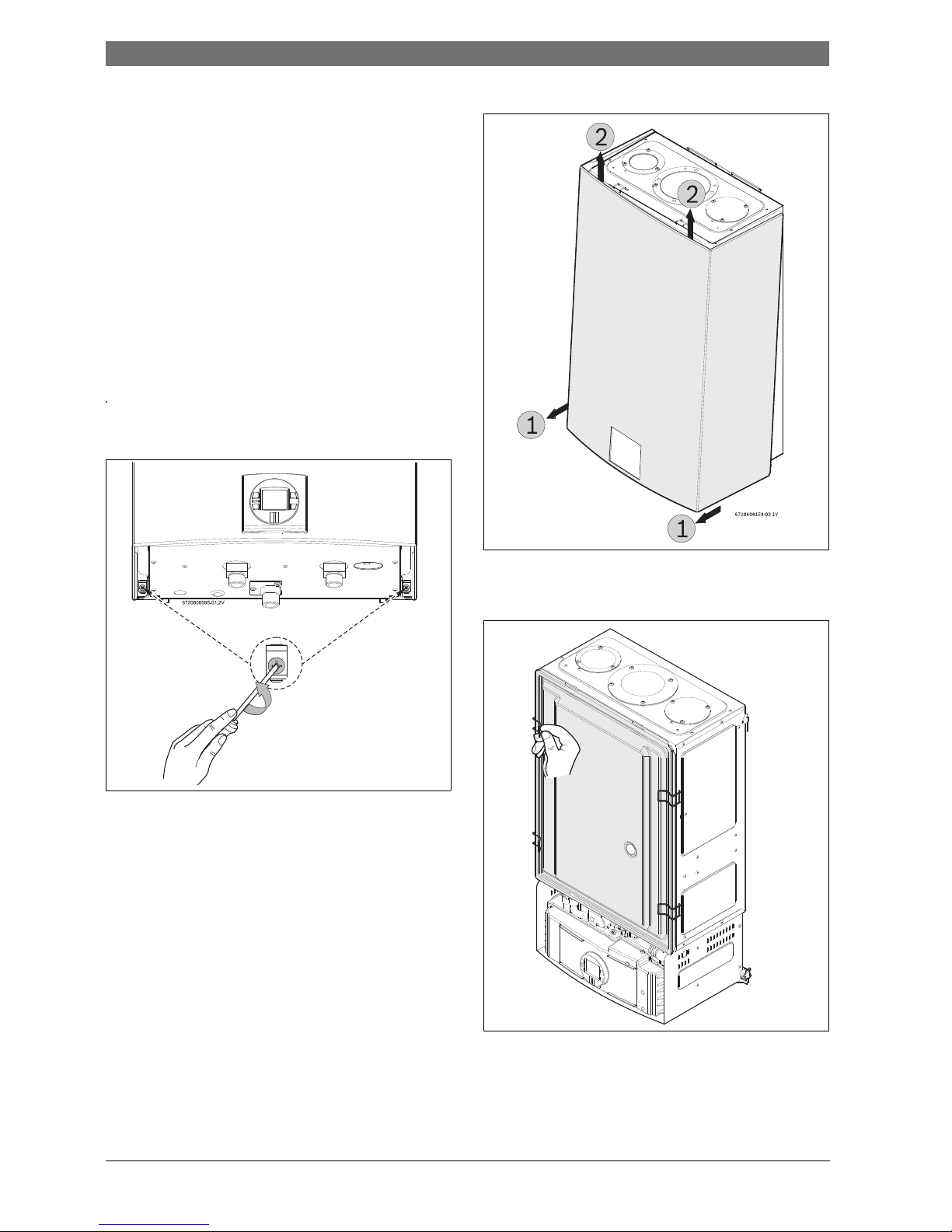
3.3.2 Remove front cover
▶ Loosen the two Phillips head screws located on bottom rear of cover.
Fig. 3 Loosen the two screws
▶ Lift front cover panel upward and remove.
Fig. 4 Remove the front cover
3.3.3 Remove combustion cover (service only)
▶ Open the four clips and remove the combustion cover.
Fig. 5 Remove the combustion cover
3.4 General rules to follow for safe operation
• 1. You must follow these instructions when you install your heater. In
the United States: The installation must conform with local codes or,
in the absence of local codes, the National Fuel Gas Code ANSI
Z223.1/NFPA 54.
6720644956-11.1V
Appliance details | 9
6 720 644 936 (2013/01)830 ES
In Canada: The Installation must conform with CSA B149.(1,2)
INSTALLATION CODES and /or local installation codes.
• 2. Carefully plan where you install the heater. Correct combustion air
supply and vent pipe installation are very important. If not installed
correctly, fatal accidents can occur, such as carbon monoxide
poisoning or fire.
• 3. When the unit is installed indoors and ROOM SEALED (twin pipe) it
is permitted to be located in bathrooms, bedrooms and occupied
rooms that are normally kept closed. See chapter 4.3 (page 10). If the
unit will be installed indoors and use indoor combustion air, the place
where you install the heater must have enough ventilation. The
National Fuel Gas Codes do not allow UNSEALED gas fired water
heater installations in bathrooms, bedrooms or any occupied
rooms normally kept closed. See chapter 4.4 (page 23).
• 4. You must correctly vent your heater. See chapter 4.3 (page 10) on
VENTING.
• 5. The appliance and its gas connection must be leak tested before
placing the appliance in operation.
The appliance must be isolated from the gas supply piping system by
closing its individual manual gas shutoff valve (not supplied with
heater) during any pressure testing at pressures in excess of ½ Psig
(3.5 kPa).
• 6. Keep water heater area clear and free from combustibles and
flammable liquids. Do not locate the heater over any material which
might burn.
• 7. Correct gas pressure is critical for the proper operation of this
heater. Gas piping must be sized to provide the required pressure at
the maximum output of the heater, while all the other gas appliances
are in operation. Check with your local gas supplier, and see the
section on connecting the gas supply. See chapter 4.9 (page 26).
• 8. Should overheating occur or the gas supply fail to shut off, turn off
the gas supply at the manual gas shut off valve, on the gas line. Note:
manual gas shutoff valve is not supplied with the heater but must be
field installed.
• 9. Do not use this appliance if any part has been underwater.
Immediately call a qualified service technician to inspect the
appliance and to replace any part of the control system and any gas
control which has been underwater.
• 10. Failure to install heater correctly may lead to unsa fe operation and
void the warranty.
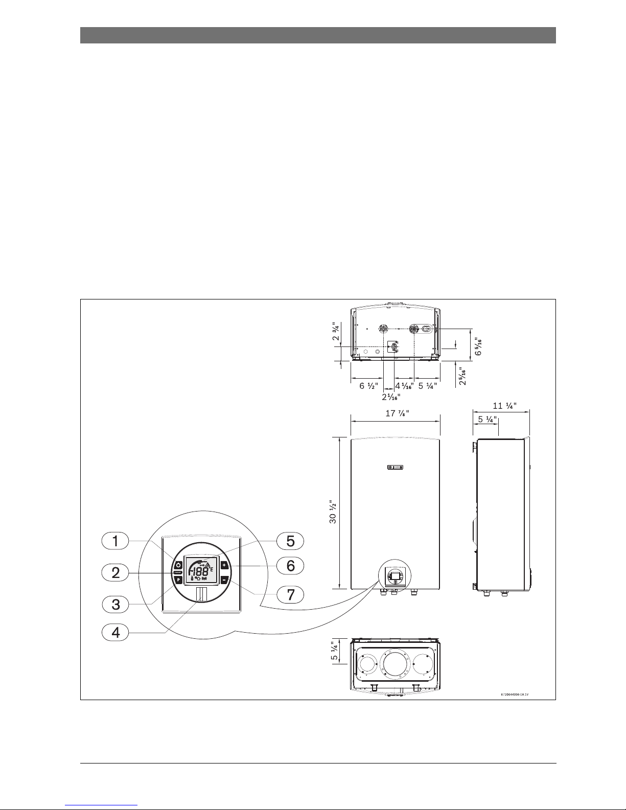
3.5 Dimensions and minimum installation clearances
Fig. 6 Dimensions
[1] On/Off button
[2] Reset button
[3] Program key
[4] Power ON or stand-by LED
[5] LCD display
[6] Up button
[7] Down button
10 | Installation instructions
830 ES6 720 644 936 (2013/01)
Fig. 7 Side view
4 Installation instructions
4.1 Specialized tools
The following specialized tools may be required for installation:
•Manometer
• Multi-meter
• Combustion Gas Analyzer
4.2 Introduction
Please follow these instructions. Failure to follow instructions may
result in:
▶ Damage or injury.
▶ Improper operation.
▶ Loss of warranty.
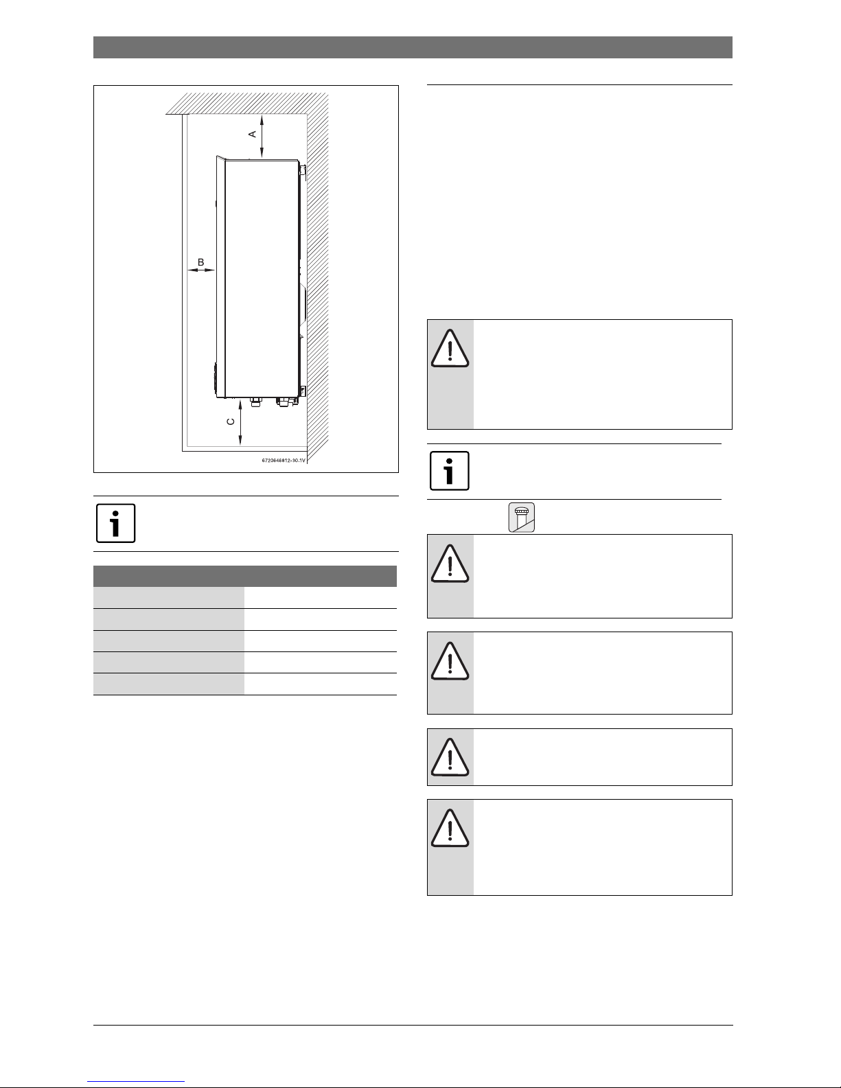
4.3 Venting
For servicing access, a 2ft clearance is recommended to
the front cover.
Model 830 ES
TOP (A) 12”
FRONT (B) 1”
BACK 0”
SIDES 1”
FLOOR (C) 12”
Table 4 Minimum clearances
DANGER:
▶ The water heater must be installed by a qualified
installer in accordance with these instructions. If
improperly installed, a hazardous condition such as
explosion or carbon monoxide poisoning could result.
Bosch Thermotechnology Corp. is not responsible for
improperly installed appliances.
Common installation practice is to first determine the
venting/combustion air point of termination, then
design the piping layout back to the heater.
NOTICE:
▶ Do not reduce the exhaust or combustion air vent pipe
sizes.
▶ D o not common vent with any other vented appliance
or stove.
DANGER: Flue gas poisoning!
▶ Failure to vent the exhaust gases to the outside with
sealed stainless steel vent pipe (AL29-4C) may result
in dangerous flue gases filling the structure in which it
is installed.
WARNING:
▶ Do not mix vent pipe or joining methods from
different manufacturers.
WARNING:
▶ Approved terminators must be used for inlet and
exhaust vent systems to prevent rain from entering
the appliance. Failure to do so may result in damage to
the appliance. This failure is not covered under the
manufacturer’s warranty.
Installation instructions | 11
6 720 644 936 (2013/01)830 ES
4.3.1 Vent material
Establish vent clearances that comply with the vent manufacturer's
specifications. In all cases, follow local codes. See table 5:
Horizontal venting systems only:
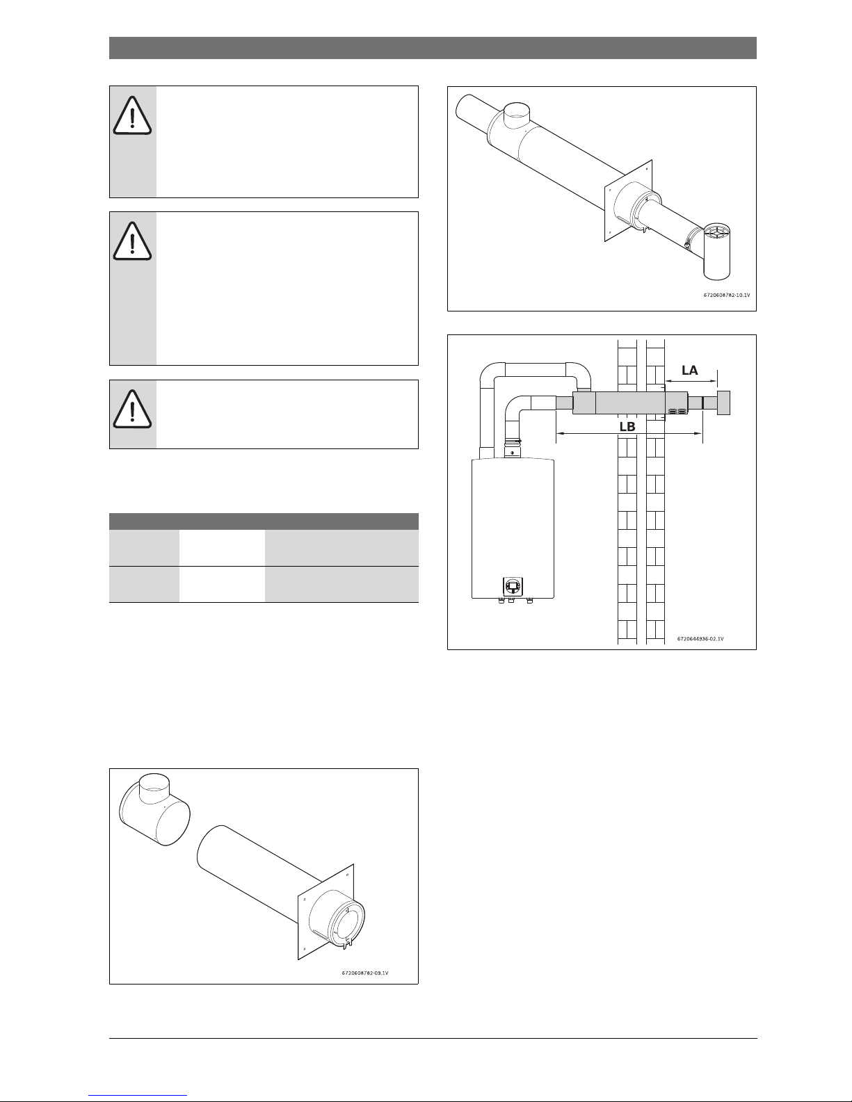
An optional stainless concentric vent/air intake termination can be used
to provide only one penetration point through the exterior wall (see fig.
8, 9 & 10). The concentric vent/air intake kit can be ordered from your
local wholesaler. (Part# ESHCK). Note: Only tee terminals are approved
for use with the concentric vent/air intake kit (see Table 6). Vent piping
and tee terminal used with kit must be from the same vent pipe
manufacturer. The appliance can also be installed with separate air
intake and exhaust piping (see Fig.16).
Fig. 8 Concentric kit part # ESHCK
Fig. 9 Concentric kit vent assembly
Fig. 10 Concentric kit installation
[LA] 12 inches
[LB] 3 inches stainless steel pipe
CAUTION:
▶ The vent system must be installed by a qualified
installer in accordance with these instructions. If
improperly installed, a hazardous condition such as
explosion or carbon monoxide poisoning coul d result.
Bosch Water Heating will not be responsible for
improperly installed appliances.
NOTICE:
▶ In areas where outside temperatures routinely come
close to freezing, sealed combustion operation is
required. Concentric termination or separate
terminations for combustion and vent, must be
installed on the same wall or roof surface; however,
never facing the direction of prevailing winds. Failure
to do so may result in heat exchanger freezing and
bursting. This failure is not covered under the
manufacturer's warranty.
WARNING: Appliance malfunction!
▶ Protect the exhaust and inlet from leaves and debris
by installing a screen on the end of the termination.
¼ " mesh minimum opening recommen ded on screen.
Item Diam. Material
Exhaust Vent 3 or 4 inches Sealed single wall stainless steel
(AL29-4C)
Intake Vent PVC Sealed PVC or any other rigid pipe
Table 5 Venting Specifications
12 | Installation instructions
830 ES6 720 644 936 (2013/01)
4.3.2 Vent specifications
Install appliance as close to point of vent termination as possible. The
exhaust piping must vent directly to the outside of the structure.
Horizontal sections of vent must pitch upward towards termination ¼"
for every foot of horizontal length, to prevent the pooling of condensate,
and be supported at 4 foot intervals with overhead hangers.
Exception: horizontal run between last elbow and termination must
pitch down to termination 1/4" per foot. Note: For horizontal
terminations, venting must terminate once it penetrates to the outside of
the structure. There must be no sections of vent pipe exposed to the
outdoors other than the termination. Note: Listed thimbles or collars are
necessary where venting passes through wall and ceiling partitions. If
the vent system passes through combustible areas where the vent
clearance requirements cannot be maintained, it is permissible to chas e
straight sections of sealed 3 inch single wall vent through 4 inch (or
greater) Type-B vent. The distance to combustibles using this chase
technique is 1 inch. Note: Type-B vent must never be used as the actual
exhaust vent system for the appliance, as it is not gas tight and illegal for
use with this appliance. This will create a serious health hazard and void
the warranty.
For specific questions concerning vent material, specifications, usage or
installation, please contact the vent manufacturer directly.
Condensate drain requirements
An external condensate drain (not supplied with the heater) must be
installed under the following conditions:
• All vertical terminating vent installations.
• Horizontal terminating vent installations where the total linear vent
length is greater than 10 feet (3.1 m) for 3" and 5 feet (1.5 m) for 4".
• Vent installations where any section of the exhaust vent pipe passes
through an unconditioned space.
Twin pipe termination clearances
The minimum clearance between exhaust vent and combustion air inlet
terminations for twin pipe penetration is 3 feet.
Minimum combustion air and exhaust pipe length
The minimum exhaust pipe length is 1 foot (0.3m) of straight vent pipe.
The minimum combustion air pipe length is one 90° elbow.
Maximum combustion air and exhaust pipe length
The following tables display the maximum allowable straight pipe
lengths for combustion air and exhaust piping with consideration to the
number of elbows used. Reduce the equivalent length for each elbow
used from the maximum allowable length depending on the system
used.
Use of elbows
It is recommended to limit the amount of elbows used in the exhaust and
combustion air piping to reduce friction in the air flow. The following lists
the maximum amount of 90° elbows allowed in either the exhaust or
combustion air piping:
3" VENTING Z flex Protech Heat Fab
3"
90° elbow
2SVEEWCF0390 FSELB9003 9314
3" Tee
Terminal
2SVSTTF03 FSTT3 9390TEE
3" Horizontal
Terminal
2SVSTB03 FSTB3 N/A
3" horiz.
terminal
with damper
2SVSHTD03 N/A N/A
3" Vertical
Terminal
2SVSRCF03 FSRC3 5300CI
Table 6 3" Terminator Part Numbers
4" VENTING Z flex Protech Heat Fab
4"
90° elbow
2SVEEWCF0490 FSELB9004 9414
4" Tee
Terminal
2SVSTTF04 FSTT4 9490TEE
4" Horizontal
Terminal
2SVSTB04 FSTB4 N/A
4" horiz.
terminal
with damper
2SVSHTD04 FSRC4 5400CI
4" vertical
terminal
2SVSRCF04 N/A N/A
Table 7 4" Terminator Part Numbers
Company Contact info
Z-flex www.z-flex.com
800-654-5600
ProTech Industries www.protechinfo.com
800-766-3473
Heat-Fab www.heatfab.com
800-772-0739
Table 8 Vent manufacturers
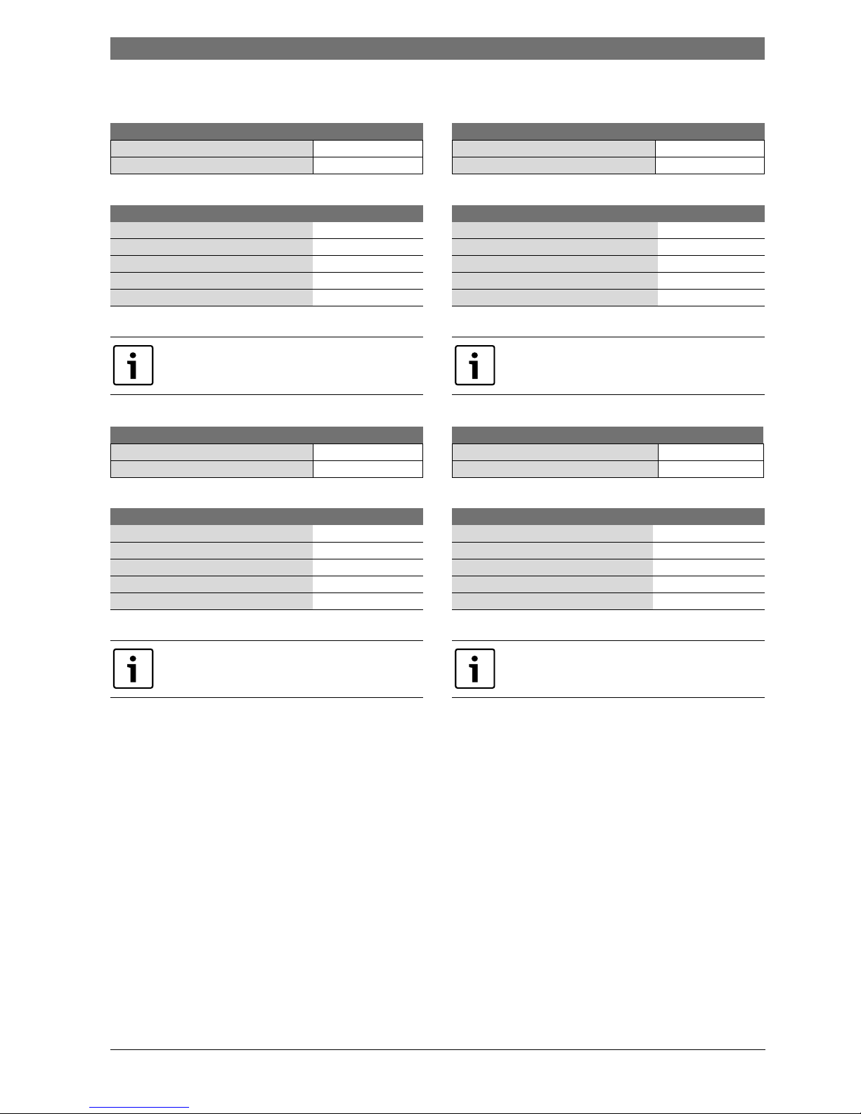
Venting Maximum
allowable
Exhaust pipe
length
Maximum
allowable
Combustion air
pipe length
Elbow Equivalency
90° 45°
3" 28,5 ft 28,5 ft 2,5 ft 1,25 ft
4" 61,25 ft 61,25 ft 1,25 ft 0,75 ft
Table 9 Maximum Allowable Exhaust and Combustion Air Lengths
Max. number of 90° elbows 3" venting 4" venting
Max number of elbows 5 7
Table 10
Two 45° elbows are equal to one 90° elbow. Any
combination of 45° and 90° elbows may be used in
the vent system as long as the combination does not
exceed the maximum listed in table 9 above.
Installation instructions | 13
6 720 644 936 (2013/01)830 ES
Calculation example for 3" venting:
Exhaust
Combustion air
Calculation example for 4" venting:
Exhaust
Combustion air
System used Concentric
Number of 90° elbows needed: 1
Number of 45° elbows needed: 2
Table 11
Calculation of example
Max. length 28,5’
90° elbow reduction - 2,5’
sub-total = 26’
45° elbow reduction - 2,5’
Total = 23,5’
Table 12
For this example, the maximum allowable exhaust pipe
length is 23,5 feet.
System used Concentric
Number of 90° elbows needed: 2
Number of 45° elbows needed: 1
Table 13
Calculation of example
Max. length 28,5’
90° elbow reduction - 5’
sub-total = 23,5’
45° elbow reduction - 1,25’
Total = 22,25’
Table 14
For this example, the maximum allowable combustion
air pipe length is 22,25 feet.
System used Twin pipe
Number of 90° elbows needed: 2
Number of 45° elbows needed: 2
Table 15
Calculation of example
Max. length 61,25’
90° elbow reduction - 2,5’
sub-total = 58,75’
45° elbow reduction - 1,5’
Total = 57,25’
Table 16
For this example, the maximum allowable exhaust pipe
length is 57,25 feet.
System used Twin pipe
Number of 90° elbows needed: 1
Number of 45° elbows needed: 2
Table 17
Calculation of example
Max. length 61,25’
90° elbow reduction - 1,25’
sub-total = 60’
45° elbow reduction - 1,5’
Total = 58,5’
Table 18
For this example, the maximum allowable combustion
air pipe length is 58,5 feet.
14 | Installation instructions
830 ES6 720 644 936 (2013/01)
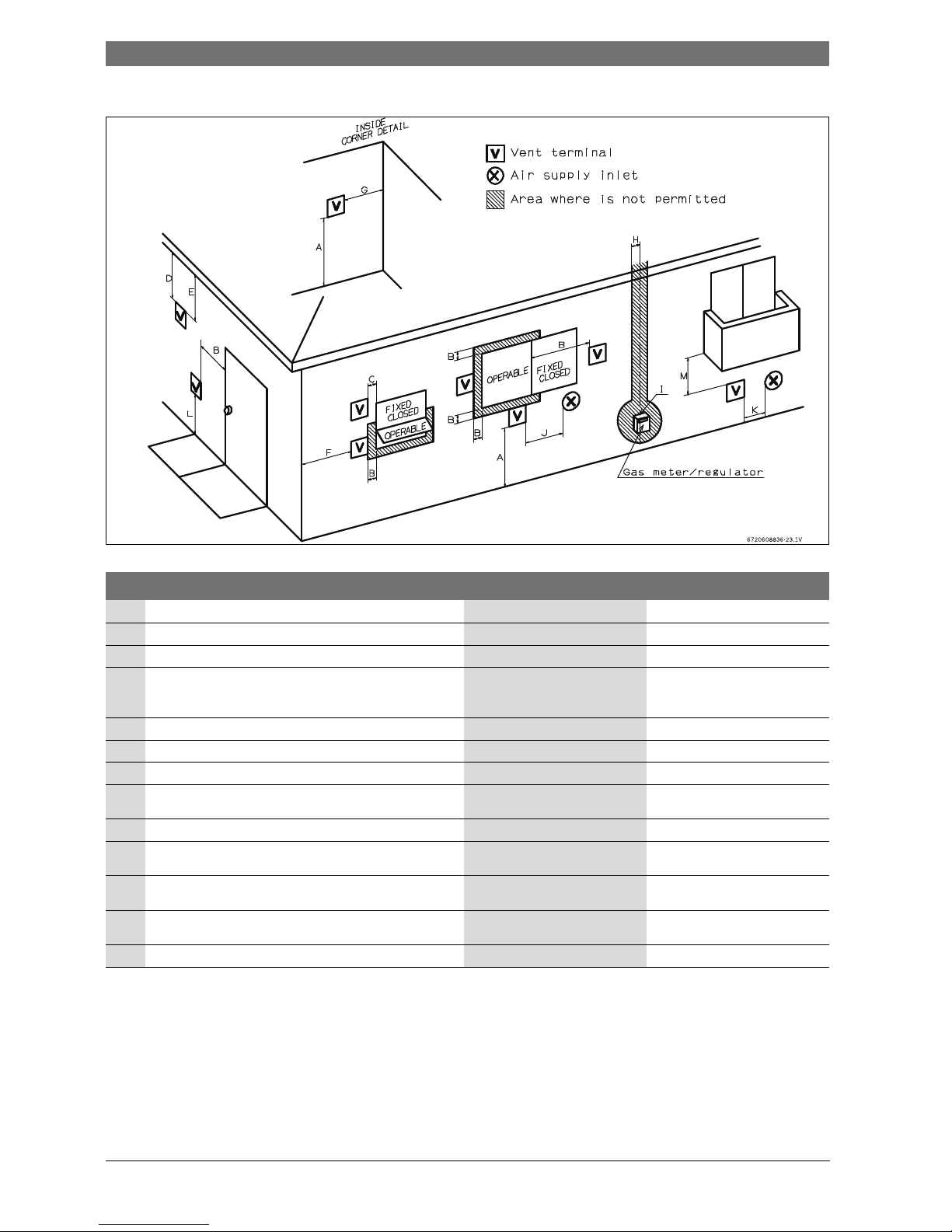
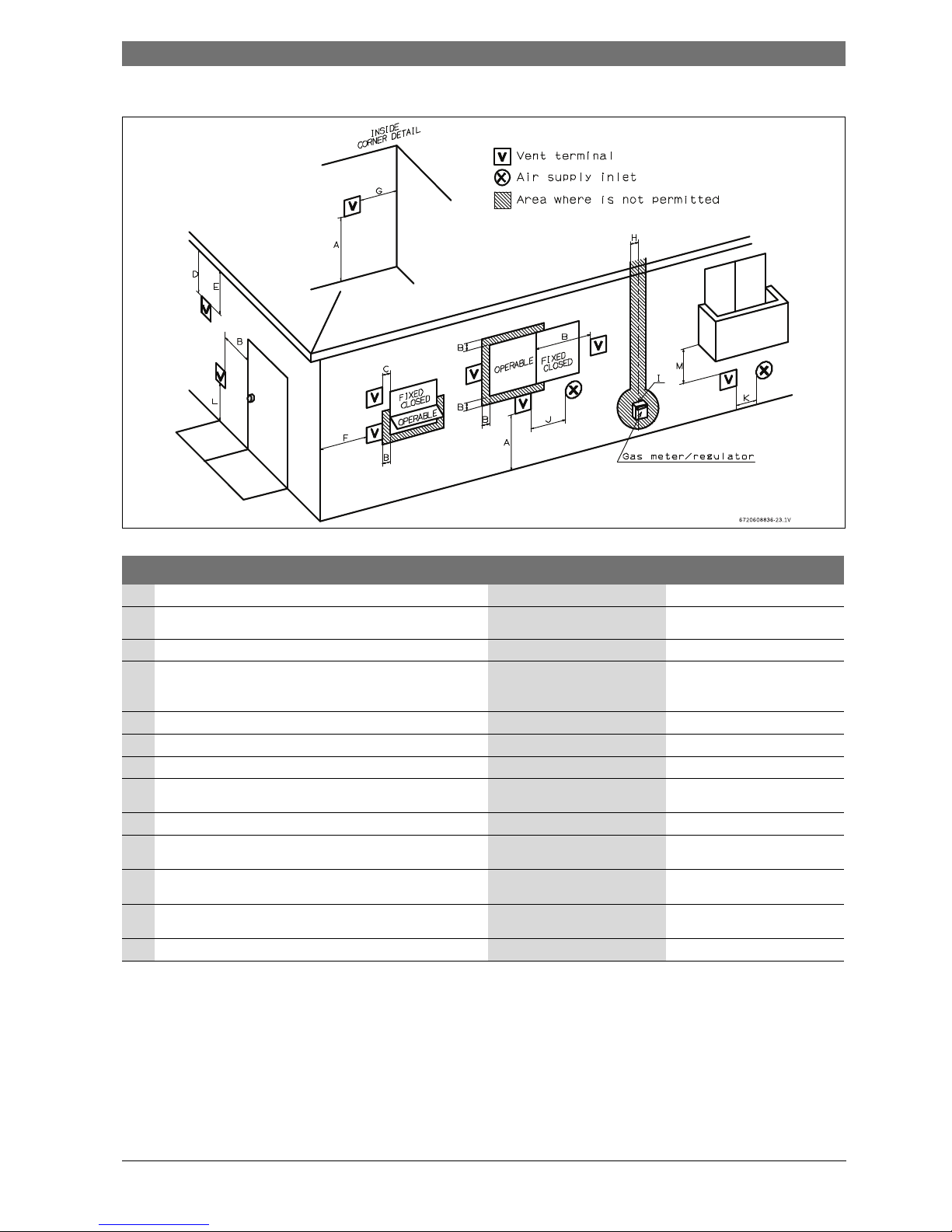
Required direct vent terminal clearances (twin pipe / concentric penetration)
Fig. 11
[*] For clearances not specified in ANSI Z223.1 / NFPA 54 or CSA-B149.1, one of the following shall be indicated:
a) A minimum clearance value determined by testing in accordance with section 2.20, or;
b) A reference to the following footnote:
“Clearance in accordance with local installation codes and the requirements of the gas supplier.”
Canadian installations
1)
U.S. installations
2)
A Clearance above grade, veranda, porch, deck or balcony 12 in. 12 in.
B Clearance to window or door that may be opened 36 in. 12 in.
C Clearance to permanently closed window **
D Vertical clearance to ventilated soffit located above the vent
termination within a horizontal distance of 2 feet (61cm) from
the center line of the termination
**
E Clearance to unventilated soffit **
F Clearance to outside corner **
G Clearance to inside corner **
H Clearance to each side of center line extended above meter/
regulator assembly
36 in. within a height 15 feet above
meter/ regulator assembly
*
I Clearance to service regulator vent outlet 36 in. *
J Clearance to non-mechanical air supply inlet to building or the
combustion air inlet to any other application
36 in. 12 in.
K Clearance to mechanical air supply inlet 72 in. 36 in. above if within 10 feet
horizontally
L Clearance above paved sidewalk or paved driveway located on
public property
84 in.
3)
*
M Clearance under veranda, porch deck or balcony 12 in.
4)
*
Table 19
1) In accordance with the current CSA B149.1 Natural Gas and Propane Installation Code.
2) In accordance with the current ANSI Z223.1 / NFPA 54 National Fuel Gas Co de.
3) A vent shall not terminate directly above a sidewalk or paved driveway that is located between two single family dwellings and serves both dwellings.
4) Permitted only if veranda, porch, de ck or balcony is fully open on a minimum of two sides beneath the floor.
Installation instructions | 15
6 720 644 936 (2013/01)830 ES
Required other than direct vent terminal clearances (single pipe penetration)
Fig. 12
[*] For clearances not specified in ANSI Z223.1 / NFPA 54 or CSA-B149.1, one of the following shall be indicated:
a) A minimum clearance value determined by testing in accordance with section 2.20, or;
b) A reference to the following footnote:
“Clearance in accordance with local installation codes and the requirements of the gas supplier.”
Canadian installations
1)
U.S. installations
2)
A Clearance above grade, veranda, porch, deck or balcony 12 in. 12 in.
B Clearance to window or door that may be opened 36 in. 4 feet below or to side of opening;
1 foot above opening
C Clearance to permanently closed window **
D Vertical clearance to ventilated soffit located above the vent
termination within a horizontal distance of 2 feet (61cm) from the
center line of the termination
**
E Clearance to unventilated soffit **
F Clearance to outside corner **
G Clearance to inside corner **
H Clearance to each side of center line extended above meter/
regulator assembly
36 in. within a height 15 feet above
meter/ regulator assembly
*
I Clearance to service regulator vent outlet 36 in. *
J Clearance to non-mechanical air supply inlet to building or the
combustion air inlet to any other application
36 in. 4 feet below or to side of opening;
1 foot above opening
K Clearance to mechanical air supply inlet 72 in. 36 in. above if within 10 feet
horizontally
L Clearance above paved sidewalk or paved driveway located on
public property
84 in.
3)
84 in.
M Clearance under veranda, porch deck or balcony 12 in.
4)
*
Table 20
1) In accordance with the current CSA B149.1 Natural Gas and Propane Installation Code
2) In accordance with the current ANSI Z223.1 / NFPA 54 National Fuel Gas Co de
3) A vent shall not terminate directly above a sidewalk or paved driveway that is located between two single family dwellings and serves both dwellings.
4) Permitted only if veranda, porch, de ck or balcony is fully open on a minimum of two sides beneath the floor.
16 | Installation instructions
830 ES6 720 644 936 (2013/01)
4.3.3 Vent configuration examples
Below are approved examples of vertical and horizontal venting
installations.
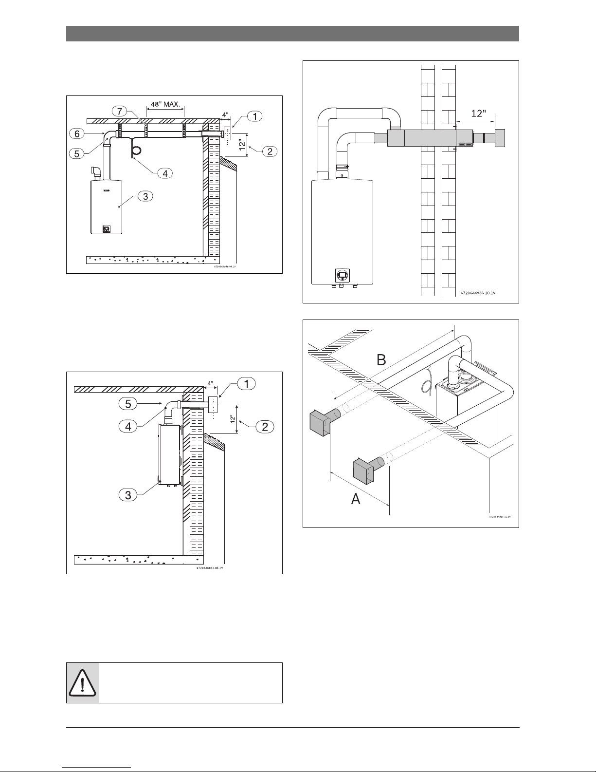
Fig. 13 Horizontal side wall venting installation (single pipe penetration)
[1] Termination
[2] Minimum above ground or normally expected snow accumulation
level
[3] Appliance
[4] Drain tee
[5] Elbow (note: minimum 1ft of straight vent pipe required)
[6] Horizontal run ¼ " per foot down to termination
[7] Hanger strap
Fig. 14 Horizontal venting installation (combustion air piping not
shown)
[1] Termination
[2] Minimum above ground or normally expected snow accumulation
level
[3] Appliance
[4] Elbow (note: minimum 1ft of straight vent pipe required)
[5] Horizontal run ¼ " per foot down to termination
Fig. 15 Horizontal venting system (concentric vent)
Fig. 16 Horizontal parallel venting system (twin pipe direct vent)
[A] 3 ft minimum
[B] 26 ft with 3" venting
60 ft with 4" venting
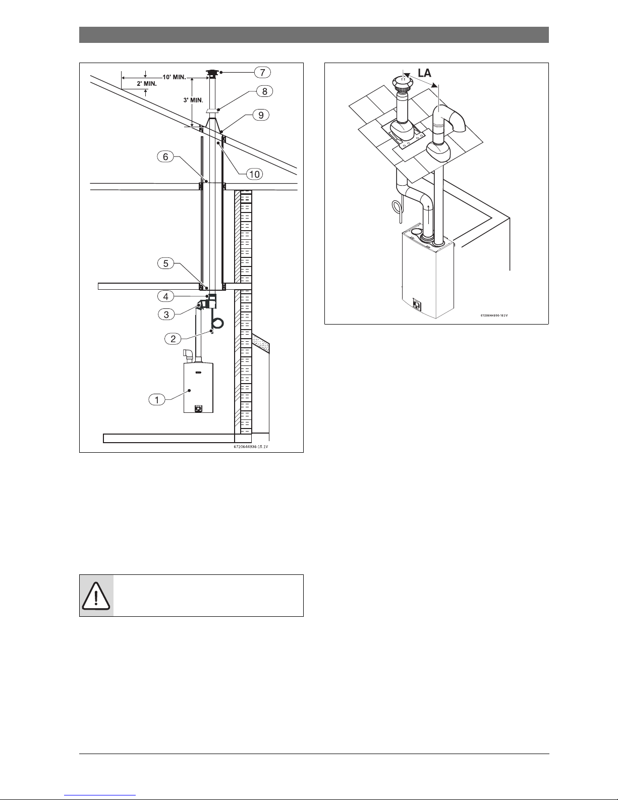
Below are approved examples of vertical venting installations.
Important:
Note: Pitch horizontal runs down toward the heater, ¼ " per foot.
WARNING:
▶ Single pipe penetration should be used in non-
freezing climates only!
Installation instructions | 17
6 720 644 936 (2013/01)830 ES
Fig. 17
[1] Appliance
[2] Condensate drain
[3] Elbow
[4] Hose clamp
[5] Firestop support
[6] Firestop support
[7] Rain cap
[8] Storm collar
[9] Flashing
[10] 4" minimum air space
Fig. 18
[LA] 3ft minimum
WARNING:
▶ Single pipe penetration should be used in non-
freezing climates only!
18 | Installation instructions
830 ES6 720 644 936 (2013/01)
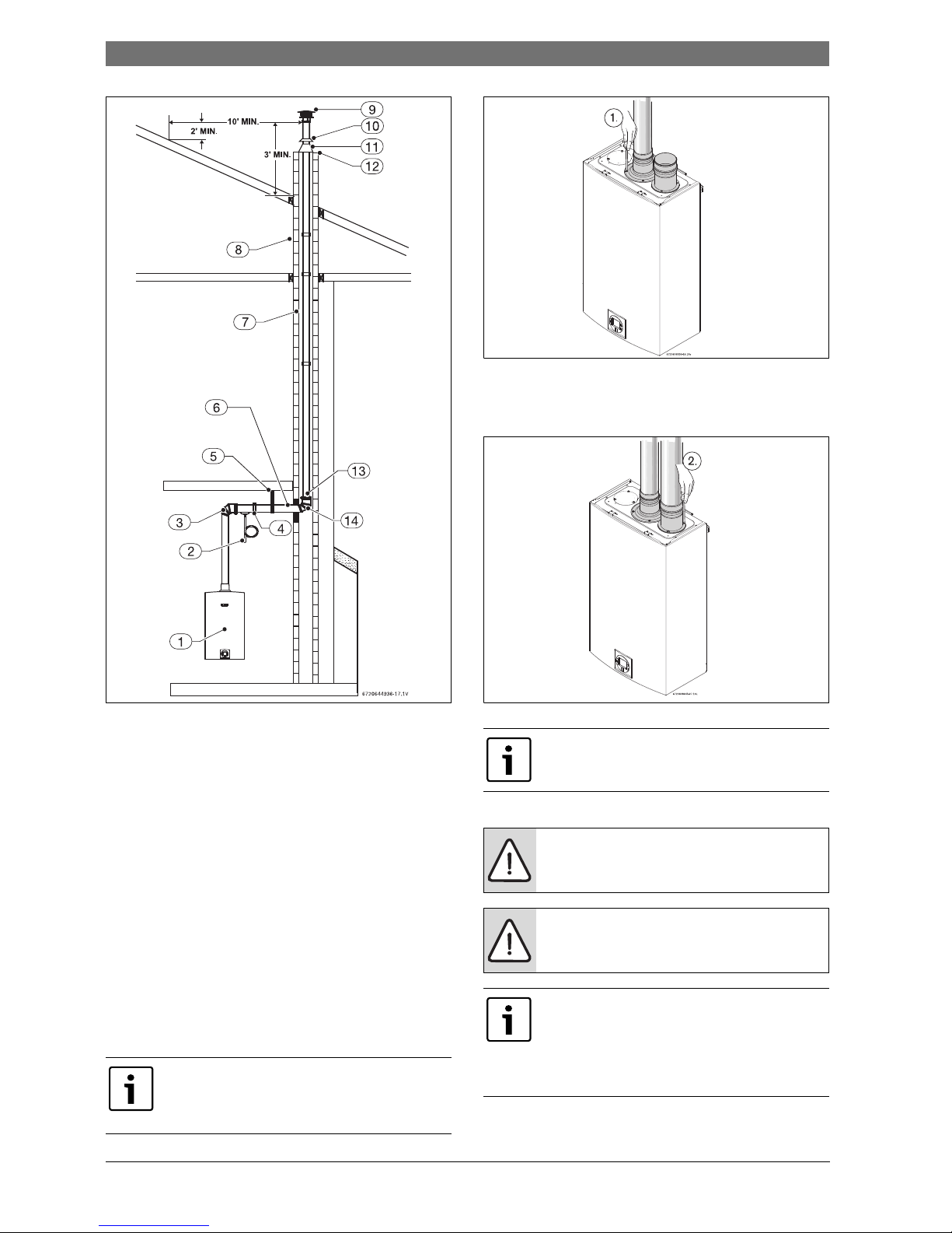
Fig. 19
[1] Appliance
[2] Condensate drain
[3] Elbow
[4] Hose clamp
[5] Hanger strap
[6] Horizontal run ¼ " rise/ft
[7] May be insulated if necessary
[8] Chimney
[9] Rain cap
[10] Storm collar
[11] Flashing
[12] Silicone seal
4.3.4 Vent connections
Attaching the exhaust and air inlet connection adaptors to the top of
the heater
▶ Attach the flue gas exhaust accessory to the top of the unit fig. 20
(position 1) using the 4 screws and gasket provided, and fully insert
vent pipe into the accessory. If using 4" venting, a 3" to 4" increaser
should be installed directly after this accessory.
Fig. 20 Exhaust connection
▶ Attach the combustion air inlet accessory to the top of the unit fig. 21
(position 2) using the 3 screws and gasket provided, and install 3" air
intake pipe over the accessory.
Fig. 21 Inlet connection
4.3.5 Connecting the external condensate water drain
If an external condensate drain (installer supplied) must be installed
(chapter 4.3.2), the following is recommended:
NOTE: Vent pipe must be completely vertical when
inserting or blue gasket inside exhaust accessory can
become displaced. Exhaust accessory can be removed
with vent pipe attached to check gasket position.
NOTE: The combustion air accessory can be installed on
the top right or on the top left side of the heater. The
combustion air inlet that is not used must be kept sealed.
NOTICE: Risk of appliance freezing!
▶ Failure to properly install condensate drain can
damage the appliance and will void the warranty.
NOTICE: Risk of appliance freezing!
▶ Do not install condensate drain tubing in areas where
it may freeze.
Use materials approved by the authority having
jurisdiction. In the absence of other authority, PVC, and
CPVC pipe must comply with ASTM D1785, F441
orD2665. Cement and primer must comply with ASTM
D2564 or F493. For Canada, use CSA or ULC certified
PVC or CPVC pipe, fittings and cement, see table 5.
 Loading...