

Page 1
VideoJet 8008 / VideoJet 8004
Page 2

Copyright
This manual is copyright protected by Bosch Security Systems. All rights
reserved. No part of this document may be reproduced or transmitted for any
purpose, by whatever method and by whatever means, electronically or mechanically, without the express written permission of Bosch Security Systems.
Issue: July 2006 (Software version 1.5)
© Copyright 2006 Bosch Security Systems
Note
This manual has been prepared with all due care and all information contained
in it has been thoroughly checked. The description was complete and correct at
the time of going to press. Our products are constantly developed and upgraded;
as such, the content of the manual is subject to change without notice.
Bosch Security Systems accepts no liability for losses that arise directly or indirectly as a result of errors, incompleteness or discrepancies between the manual
and the product described.
Trade marks
All of the hardware and software names used in this manual are highly likely to
be registered trade marks and must be treated as such.
Page 3

VideoJet 8008 / VideoJet 8004 | Installation and Operating Manual
EN | 3
Content 0
Chapter 1 Preface
Conventions . . . . . . . . . . . . . . . . . . . . . . . . . . . . . . . . . . . . . . . . .5
Intended use. . . . . . . . . . . . . . . . . . . . . . . . . . . . . . . . . . . . . . . . .6
EU Directives . . . . . . . . . . . . . . . . . . . . . . . . . . . . . . . . . . . . . . . . 6
Rating plate . . . . . . . . . . . . . . . . . . . . . . . . . . . . . . . . . . . . . . . . .6
Chapter 2 Safety information
Electric shock hazard . . . . . . . . . . . . . . . . . . . . . . . . . . . . . . . . . . 7
Installation and operation . . . . . . . . . . . . . . . . . . . . . . . . . . . . . . .8
Maintenance and repair . . . . . . . . . . . . . . . . . . . . . . . . . . . . . . . .8
Chapter 3 Product description
Components supplied. . . . . . . . . . . . . . . . . . . . . . . . . . . . . . . . . .9
System requirements for setup . . . . . . . . . . . . . . . . . . . . . . . . . .9
Configuration requirements . . . . . . . . . . . . . . . . . . . . . . . . . . . .10
Operational requirements. . . . . . . . . . . . . . . . . . . . . . . . . . . . . .10
Overview of functions . . . . . . . . . . . . . . . . . . . . . . . . . . . . . . . . . 11
Connections on the rear panel . . . . . . . . . . . . . . . . . . . . . . . . . . 14
Front panel . . . . . . . . . . . . . . . . . . . . . . . . . . . . . . . . . . . . . . . . .15
Chapter 4 Installation
Installing in a switch cabinet. . . . . . . . . . . . . . . . . . . . . . . . . . . .18
Connections . . . . . . . . . . . . . . . . . . . . . . . . . . . . . . . . . . . . . . . .20
Power on/Power off . . . . . . . . . . . . . . . . . . . . . . . . . . . . . . . . . .24
Setup using a terminal program . . . . . . . . . . . . . . . . . . . . . . . . .25
Chapter 5 Configuration using a Web browser
Connecting . . . . . . . . . . . . . . . . . . . . . . . . . . . . . . . . . . . . . . . . .29
Choosing the configuration mode. . . . . . . . . . . . . . . . . . . . . . . . 31
Unit overview . . . . . . . . . . . . . . . . . . . . . . . . . . . . . . . . . . . . . . . 33
Configuration menu . . . . . . . . . . . . . . . . . . . . . . . . . . . . . . . . . .63
Function test. . . . . . . . . . . . . . . . . . . . . . . . . . . . . . . . . . . . . . .117
Chapter 6 Operation
Operation with Microsoft Internet Explorer . . . . . . . . . . . . . . . . 119
The LIVEPAGE . . . . . . . . . . . . . . . . . . . . . . . . . . . . . . . . . . . .121
Saving snapshots . . . . . . . . . . . . . . . . . . . . . . . . . . . . . . . . . . . 124
Bosch Security Systems | 2006-07 | V1.5
Page 4

EN | 4
Installation and Operating Manual | VideoJet 8008 / VideoJet 8004
Recording video sequences . . . . . . . . . . . . . . . . . . . . . . . . . . .124
Running recording program . . . . . . . . . . . . . . . . . . . . . . . . . . .125
The MEDIA-REPLAY page . . . . . . . . . . . . . . . . . . . . . . . . . . .126
Backup . . . . . . . . . . . . . . . . . . . . . . . . . . . . . . . . . . . . . . . . . . .130
Installing MPEG viewer . . . . . . . . . . . . . . . . . . . . . . . . . . . . . .131
Hardware connections between video servers. . . . . . . . . . . . . 132
Operation with decoder software . . . . . . . . . . . . . . . . . . . . . . . 134
Operating options on the front panel . . . . . . . . . . . . . . . . . . . .135
Chapter 7 Maintenance and upgrades
Testing the network connection . . . . . . . . . . . . . . . . . . . . . . . .139
Restart (Reset) . . . . . . . . . . . . . . . . . . . . . . . . . . . . . . . . . . . . .139
Repairs . . . . . . . . . . . . . . . . . . . . . . . . . . . . . . . . . . . . . . . . . . .140
Transfer and disposal. . . . . . . . . . . . . . . . . . . . . . . . . . . . . . . . 140
Chapter 8 Appendix
Troubleshooting . . . . . . . . . . . . . . . . . . . . . . . . . . . . . . . . . . . .141
LEDs. . . . . . . . . . . . . . . . . . . . . . . . . . . . . . . . . . . . . . . . . . . . .143
RS232/485 interface. . . . . . . . . . . . . . . . . . . . . . . . . . . . . . . . .144
RS232 interface (audio versions only) . . . . . . . . . . . . . . . . . . .145
Terminal block . . . . . . . . . . . . . . . . . . . . . . . . . . . . . . . . . . . . .146
Second terminal block (audio versions only) . . . . . . . . . . . . . .147
Glossary . . . . . . . . . . . . . . . . . . . . . . . . . . . . . . . . . . . . . . . . . .148
Technical data: VideoJet 8008 . . . . . . . . . . . . . . . . . . . . . . . . .150
Technical data: VideoJet 8008 with audio . . . . . . . . . . . . . . . . 152
Technical data: VideoJet 8004 . . . . . . . . . . . . . . . . . . . . . . . . .154
Technical data: VideoJet 8004 with audio . . . . . . . . . . . . . . . . 156
Chapter 9 Index
Bosch Security Systems | 2006-07 | V1.5
Page 5
VideoJet 8008 / VideoJet 8004 | Installation and Operating Manual
EN | 5
Preface 1
This manual is intended for persons responsible for the installation and operation of the VideoJet 8008 or VideoJet 8004. International, national and any
regional electrical engineering regulations must be followed at all times. Relevant knowledge of network technology is required. The manual describes the
installation and operation of the unit.
Conventions
In this manual, the following symbols and notations are used to draw attention
to special situations:
Caution
This symbol indicates that failure to follow the safety instructions described
may endanger persons and cause damage to the unit or other equipment.
It is associated with immediate, direct hazards.
Note
This symbol refers to features and indicates tips and information for easier,
more convenient use of the unit.
Bosch Security Systems | 2006-07 | V1.5 Preface
Page 6

EN | 6
Installation and Operating Manual | VideoJet 8008 / VideoJet 8004
Intended use
The VideoJet 8008 and VideoJet 8004 network video servers transmit video and
control signals over data networks (Ethernet LAN, Internet). The integrated hard
drive allows you to use the device as a DVR. Audio signals can also be transmitted with the audio versions of the units. The units are designed for use in
CCTV systems. Various functions can be triggered automatically by incorporating external alarm sensors. Other applications are not permitted.
In the event of questions concerning the use of the units which are not answered
in this manual, please contact your sales partner or:
Bosch Sicherheitssysteme GmbH
Robert-Koch-Straße 100
85521 Ottobrunn
Germany
www.bosch-sicherheitssysteme.de
EU Directives
The VideoJet 8008 and VideoJet 8004 network video servers comply with the
requirements of EU Directives 89/336 (Electromagnetic Compatibility) and
73/23, amended by 93/68 (Low Voltage Directive).
Rating plate
For exact identification, the model name and serial number are inscribed on the
bottom of the housing. Please make a note of this information before installation
if necessary so as to have it to hand in case of questions or when ordering spare
parts.
Preface Bosch Security Systems | 2006-07 | V1.5
Page 7

VideoJet 8008 / VideoJet 8004 | Installation and Operating Manual
EN | 7
Safety information 2
Electric shock hazard
❚ Never attempt to connect the unit to any power network other than the type
for which it is intended.
❚ Never open the housing.
❚ If a fault occurs, disconnect the unit from the power supply and from all other
units.
❚ Install the unit only in dry, weather-protected locations.
❚ If safe operation of the unit cannot be ensured, remove it from service and
secure it to prevent unauthorized operation. Safe operation is no longer possible in the following cases:
– if there is visible damage to the unit or power cables,
– if the unit no longer operates correctly,
– if the unit has been exposed to rain or moisture,
– if foreign bodies have penetrated the unit,
– after long storage under adverse conditions, or
– after exposure to extreme stress in transit.
In such cases, have the unit checked by Bosch Security Systems.
Bosch Security Systems | 2006-07 | V1.5 Safety information
Page 8

EN | 8
Installation and Operating Manual | VideoJet 8008 / VideoJet 8004
Installation and operation
❚ The relevant electrical engineering regulations and guidelines must be com-
plied with at all times during installation.
❚ Relevant knowledge of network technology is required to install the unit.
❚ Before installing or operating the unit, make sure you have read and under-
stood the documentation for the other equipment connected to it, such as
cameras. The documentation contains important safety instructions and
information about permitted uses.
❚ Perform only the installation and operation steps described in this manual.
Any other actions may lead to personal injury, damage to property or damage
to the equipment.
Maintenance and repair
❚ Never open the housing of a VideoJet 8008 or VideoJet 8004. The units do
not contain any user-serviceable parts.
❚ Ensure that all maintenance or repair work is carried out only by qualified per-
sonnel (electrical engineers or network technology specialists).
Safety information Bosch Security Systems | 2006-07 | V1.5
Page 9

VideoJet 8008 / VideoJet 8004 | Installation and Operating Manual
EN | 9
Product description 3
Components supplied
❚ VideoJet 8008 or VideoJet 8004 network video server
(basic version or audio version)
❚ Power supply cable
❚ Configuration cable
❚ Mounting kit for installation in 19-inch racks
❚ Quick Installation Guide
❚ Product CD with the following content:
– Quick Installation Guide
– Manual
– System Requirements document
– MPEG ActiveX control
– MPEG viewer
– DirectX control
– Microsoft Internet Explorer
– Microsoft Virtual Machine
– Adobe Acrobat Reader
System requirements for setup
❚ Computer with Windows 2000/XP operating system, access to a network and
Microsoft Internet Explorer (version 6.0 or higher)
or
❚ Computer with Windows 2000/XP operating system, free serial interface and
terminal program
Bosch Security Systems | 2006-07 | V1.5 Product description
Page 10
EN | 10
Installation and Operating Manual | VideoJet 8008 / VideoJet 8004
Configuration requirements
❚ Computer with Windows 2000/XP operating system, access to a network and
Microsoft Internet Explorer (version 6.0 or higher)
or
❚ Computer with Windows 2000/XP operating system, access to a network and
receiver software, such as VIDOS
Note
Also note the information in the System Requirements document on the
product CD supplied.
Make sure the graphics card is set to 16- or 32-bit color depth and that
Microsoft Virtual Machine is installed and activated on your PC.
If necessary, you can install the required software and controls from the
product CD supplied (see Components supplied, page 9).
Operational requirements
❚ Computer with Windows 2000/XP operating system, access to a network and
Microsoft Internet Explorer (version 6.0 or higher)
or
❚ Computer with Windows 2000/XP operating system, access to a network and
receiver software, such as VIDOS
or
❚ MPEG-4 compatible hardware decoder from Bosch Security Systems
(for example VIP XD) as a receiver and connected video monitor
Note
Also note the information in the System Requirements document on the
product CD supplied.
Make sure the graphics card for reception on the computer monitor is set
to 16- or 32-bit color depth and that Microsoft Virtual Machine is installed
and activated on your PC. If necessary, you can install the required software and controls from the product CD supplied (see Components sup-
plied, page 9).
Product description Bosch Security Systems | 2006-07 | V1.5
Page 11

VideoJet 8008 / VideoJet 8004 | Installation and Operating Manual
EN | 11
Overview of functions
Network video server
VideoJet 8008 and VideoJet 8004 are network video servers for eight independent video channels. They are primarily designed for encoding video and control
data for transmission over an IP network. With the audio versions, audio signals
can also be transmitted to and from compatible units. The use of existing networks means that integration with CCTV systems or local networks can be
achieved quickly and easily.
The VideoJet 8008 offers full D1/4CIF resolution at a complete image rate of
25 images per second for 8 channels. The VideoJet 8004 is the more economic
variant with half the image rate per channel.
VideoJet 8008 and VideoJet 8004 are designed as desktop units and intended for
installation in the switch cabinet. Mounting in a 19-inch rack using the mounting kit
supplied is a quick and easy operation.
Receiver
Compatible MPEG-4 enabled hardware decoders (for example the VIP XD) can
be used as receivers. Computers with decoding software such as VIDOS or
computers with the Microsoft Internet Explorer Web browser can also be used
as receivers.
Video encoding
VideoJet 8008 and VideoJet 8004 use the MPEG-4 video compression standard. Thanks to efficient encoding, the data rate remains low even with high
image quality and can also be adapted to local conditions within wide limits. In
this manner, the simultaneous encoding of all eight video channels is supported.
Dual Streaming in the VideoJet 8008
Dual Streaming allows the incoming data stream to be encoded simultaneously
according to two different, individually customized profiles. With VideoJet 8008,
two data streams are created per camera that can serve different purposes, for
example, one can be used for local recording and one can be optimized for
transmission over the LAN.
The VideoJet 8004 does not offer Dual Streaming.
Bosch Security Systems | 2006-07 | V1.5 Product description
Page 12

EN | 12
Installation and Operating Manual | VideoJet 8008 / VideoJet 8004
Multicast
In suitably configured networks, the multicast function enables simultaneous
real-time video transmission to multiple receivers. The UDP and IGMP V2 protocols must be implemented on the network for this function.
DVR
The integrated hard drive means that VideoJet 8008 and VideoJet 8004 can be
used as digital video recorders for local long-term recording. Both units support
ANR technology, which guarantees seamless recording without gaps with
VIDOS-NVR, even during network failures.
Remote control
For remote control of external units such as pan or tilt heads for cameras or
motorized zoom lenses, control data is transmitted via the bidirectional serial
interface. This interface can also be used to transmit transparent data.
Configuration
The units can be configured with a Web browser via the local network (Intranet)
or via the Internet. In the same way, firmware updates and fast loading of device
configurations are possible.
Snapshots
Individual video images (snapshots) can be called up from the unit, stored on the
computer's hard drive or displayed in a separate browser window in JPEG format.
Backup
The LIVEPAGE and MEDIA-REPLAY pages both contain an icon for saving the
video images shown as a file on your computer's hard drive. Video sequences
can be stored by means of a mouse click and can be redisplayed using the
MPEG viewer supplied as part of the scope of delivery.
Product description Bosch Security Systems | 2006-07 | V1.5
Page 13

VideoJet 8008 / VideoJet 8004 | Installation and Operating Manual
EN | 13
Summary
VideoJet 8008 and VideoJet 8004 offer the following main functions:
❚ Video and data transmission over IP data networks
❚ Dual Streaming function for every encoder to allow simultaneous encoding
based on two individually definable profiles (only VideoJet 8008)
❚ Multicast function for simultaneous image transmission to multiple receivers
❚ Eight independent analog BNC composite video inputs (PAL/NTSC)
❚ Video encoding to international standard MPEG-4
❚ Integrated Ethernet port (10/100/1000 Base-T)
❚ Transparent, bidirectional data channel via RS232/RS422/RS485 serial inter-
face
❚ Local long-term recording on integrated hard drive
❚ Remote control for all internal functions with TCP/IP
❚ Password protection to prevent unauthorized connection or configuration
changes
❚ Ten alarm inputs for external sensors (such as door contacts)
❚ Built-in video sensor for motion and tamper alarms
❚
Event-controlled automatic connection (for example at switch-on and for alarms)
❚ Fast and convenient configuration using built-in Web server and browser
❚ Firmware update using flash memory
❚ Convenient uploading of configuration data
The various audio versions also offer:
❚ Transmission and receipt of audio signals
❚ Bidirectional audio (mono) for line or microphone/speaker links
❚ Audio encoding to international standard G.711
❚ Five relay outputs for switching external units (such as lamps or sirens)
❚ Additional RS232 serial interface
Bosch Security Systems | 2006-07 | V1.5 Product description
Page 14
EN | 14
Installation and Operating Manual | VideoJet 8008 / VideoJet 8004
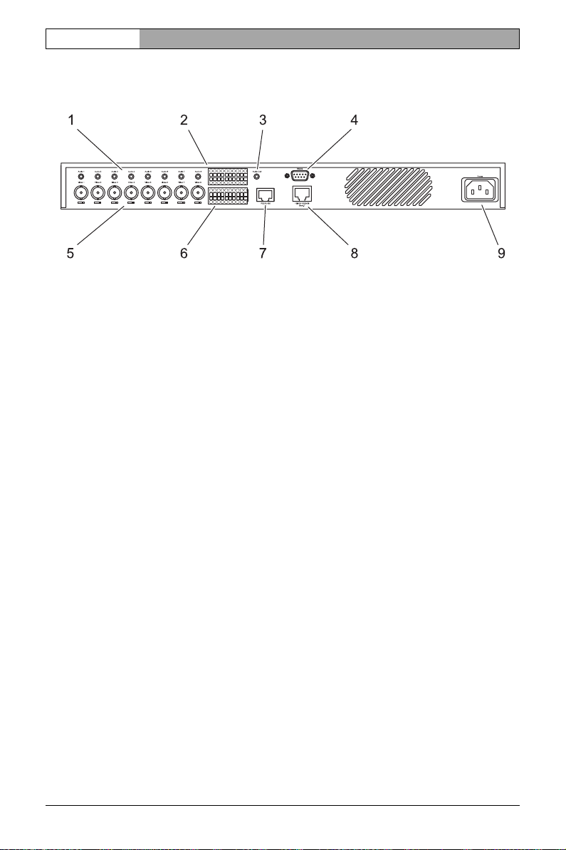
Connections on the rear panel
1 Eight audio ports (Mono): Audio 1 to Audio 8 (audio versions only)
3.5 mm stereo sockets for connecting audio cables
2 Additional terminal block (audio versions only)
Relay outputs, serial interface, audio port for microphone and loudspeaker
(speaking level)
3 Audio Out audio output (audio versions only)
3.5 mm stereo socket, stereo output with line-out level
4 RS232 serial interface (audio versions only)
9-pin sub-D socket (m) as additional serial interface
5 Eight video inputs: Video 1 to Video 8
BNC sockets for connecting the video sources,
each with a switch for 75 Ohm terminating resistance
6 Ten alarm inputs: IN
1 to IN10
Push-in terminal for connecting external signal sources or switches
7 RS232/485 serial interface
RJ45 socket for transmitting control data (standards RS232, RS422 and
RS485) and for configuration using a terminal program
8 10/100/1000 MBit Base-T RJ45 socket
for connecting to an Ethernet LAN (local network)
incl. green network connection LED (left) and
orange data transmission LED (right)
9Power socket
for connecting the power supply cable
Product description Bosch Security Systems | 2006-07 | V1.5
Page 15
VideoJet 8008 / VideoJet 8004 | Installation and Operating Manual
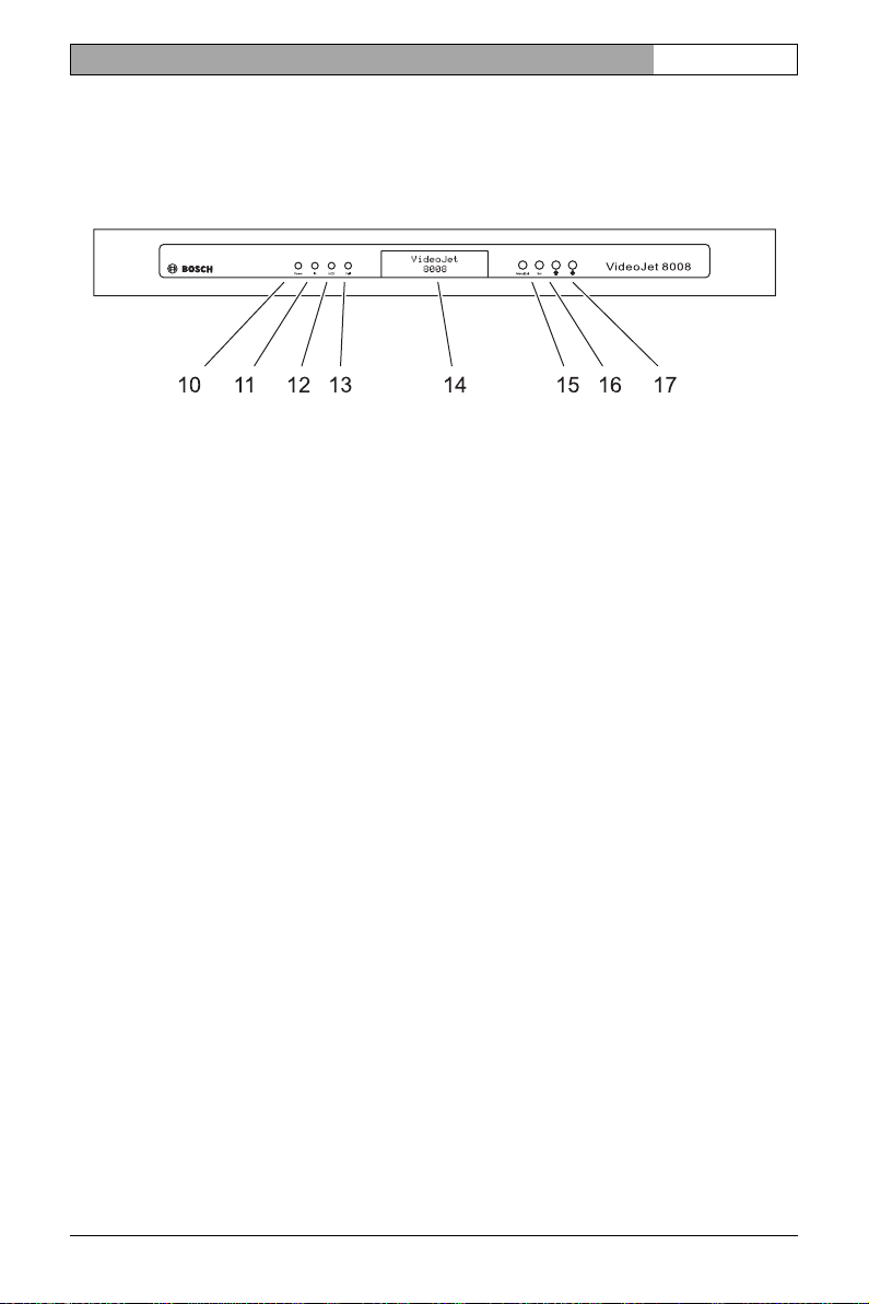
Front panel
10 Power LED
lights up green when ready for operation
11 IR diode
infrared receiver (for future function extensions)
12 HDD LED
flashes red during data transmission to and from the hard drive
13 Fail LED
flashes red during hardware error (defective fans)
EN | 15
14 Display
for displaying operating parameters
15 Menu/Exit key
for activating and deactivating the configuration menu
16 Set key
for saving changes to the operating parameters
(for future function extensions)
17 Arrow keys
for navigation in the display menu
For more information about the LEDs, see page 143.
Bosch Security Systems | 2006-07 | V1.5 Product description
Page 16

EN | 16
Installation and Operating Manual | VideoJet 8008 / VideoJet 8004
Product description Bosch Security Systems | 2006-07 | V1.5
Page 17
VideoJet 8008 / VideoJet 8004 | Installation and Operating Manual
EN | 17
Installation 4
VideoJet 8008 and VideoJet 8004 are designed as desktop units and intended
for installation in a switch cabinet. Mounting in a 19-inch rack using the mounting
kit supplied is a quick and easy operation.
For desktop operation, four self-adhesive, non-slip rubber feet are included,
which you can stick to the bottom of the unit.
Caution
The unit is designed for indoor operation. Select a suitable location for installation where the unit will not be subjected to conditions of extreme temperature or humidity. The ambient temperature must be between 0 and
+40 °C (+32 and +104 °F), and the relative humidity must not exceed 80%
(non-condensing).
The unit heats up during operation, so you should ensure that there is adequate ventilation and enough clearance between the unit and heat-sensitive objects or equipment.
Please ensure the following installation conditions:
❚ Do not install the unit close to heaters or other heat sources. Avoid locations
exposed to direct sunlight.
❚ Allow sufficient space for running cables.
❚ Ensure that the unit has adequate ventilation. Bear the total heat output in
mind, particularly when installing multiple units in a switch cabinet.
❚ When making connections, use only the cables supplied or use appropriate
cables immune to electromagnetic interference.
❚ Position and run all cables so that they are protected from damage, and pro-
vide adequate cable strain relief where needed.
❚ Avoid impacts, blows and severe vibrations as these can irreparably damage
the unit.
Bosch Security Systems | 2006-07 | V1.5 Installation
Page 18
EN | 18
Installation and Operating Manual | VideoJet 8008 / VideoJet 8004
Installing in a switch cabinet
VideoJet 8008 and VideoJet 8004 are set up for installation in a 19-inch rack.
The necessary mounting kit is already supplied.
Caution
When installing in a switch cabinet, ensure that there is sufficient ventilation
for each unit: There must be at least 5 cm (1.97 in.) of free space to the left
and right of the unit and at least 10 cm (3.94 in.) at the rear.
The ambient temperature must be between 0 and +40 °C
(+32 and +104 °F), and the relative humidity must not exceed 80%.
The unit heats up during operation, so you should ensure that there is
enough clearance between the unit and other heat-sensitive equipment or
objects.
When mounting additional units, direct contact is permitted, provided that
the surface temperature of the adjacent units does not exceed +40 °C
(+104 °F).
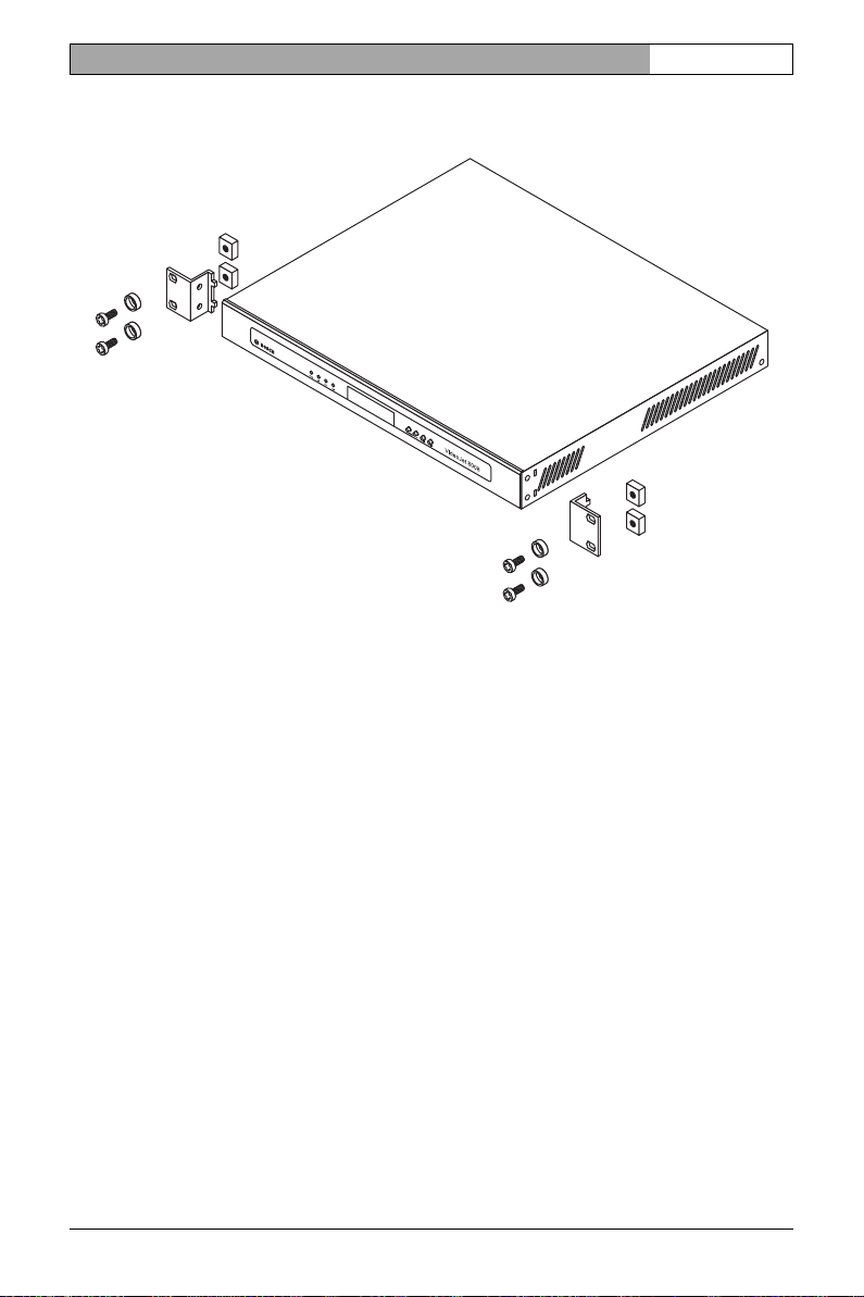
Installing the unit
– On the left and right-hand sides of the housing, loosen the two screws on
the front panel and remove them completely.
– Insert the two angle brackets from the mounting kit into the slots next to the
screw holes on the housing and secure them with the four housing screws.
– Set the unit in the switch cabinet frame and secure the angle brackets using
the four screws, washers and lock nuts provided.
– Connect the rubber connector of the power cable supplied to the
Power socket on the rear panel of the unit.
Installation Bosch Security Systems | 2006-07 | V1.5
Page 19
VideoJet 8008 / VideoJet 8004 | Installation and Operating Manual
Installation overview
EN | 19
Bosch Security Systems | 2006-07 | V1.5 Installation
Page 20
EN | 20
Installation and Operating Manual | VideoJet 8008 / VideoJet 8004
Connections
Cameras
You can connect a maximum of eight standard video sources (such as CCTV
cameras). Any cameras and other video sources that produce a standard PAL
or NTSC signal are suitable.
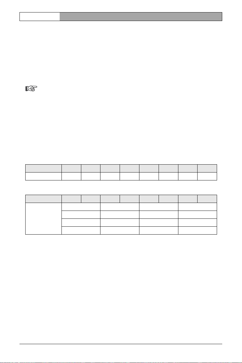
Note
On the VideoJet 8008, the maximum resolution at the complete image rate
for each camera input is Full D1/4CIF. The VideoJet 8004 only supports
the Full D1/4CIF resolution when every other camera input is assigned,
that is, when the four uneven inputs (Video 1, 3, 5, 7) or the four even inputs (Video 2, 4, 6, 8) are assigned. If all eight inputs are assigned, the
VideoJet 8004 supports a maximum resolution of 2CIF at the full image
rate. Mixed assignment is also possible: for example, assign Video 1 to
Video 4 (2CIF) and then only Video 5 and Video 7 (4CIF each).
VideoJet 8008 Video 1 Video 2 Video 3 Video 4 Video 5 Video 6 Video 7 Video 8
4CIF 4CIF 4CIF 4CIF 4CIF 4CIF 4CIF 4CIF
VideoJet 8004 Video 1 Video 2 Video 3 Video 4 Video 5 Video 6 Video 7 Video 8
4CIF — 4CIF — 4CIF — 4CIF —
—4CIF—4CIF—4CIF—4CIF
2CIF 2CIF 2CIF 2CIF 2CIF 2CIF 2CIF 2CIF
2CIF 2CIF 2CIF 2CIF 4CIF — 4CIF —
– Connect the cameras or other video sources with a video cable
(75 Ohm, BNC plug) to the BNC Video 1 to Video 8 sockets.
–Set the 75 Ω sliding switch under the BNC sockets to ●, in order to terminate
the video input, if the video signal is not looped through.
Installation Bosch Security Systems | 2006-07 | V1.5
Page 21
VideoJet 8008 / VideoJet 8004 | Installation and Operating Manual
EN | 21
Data interface
The bidirectional data interface is used to control connected units, such as a
dome camera with motorized lens. The range of controllable equipment is
expanding constantly. The manufacturers of the relevant equipment provide
specific information on installation and control.
The
RS232/485
standards. The serial interface is designed as a RJ45 socket. See
connection supports the RS232, RS422 and RS485 transmission
page
144 for
the pin assignment.
Caution
Please take note of the appropriate documentation when installing and operating the unit to be controlled. The documentation contains important
safety instructions and information about permitted uses.
Note
A video connection is necessary to transmit transparent data.
Network
You can connect the unit to a 10/100/1000 Base-T network using a standard
UTP category 5 cable with RJ45 connectors.
– Connect the unit to the network via the 10/100/1000 MBit Base-T socket.
Alarm inputs
VideoJet 8008 and VideoJet 8004 offer ten alarm inputs via an orange terminal
block. The alarm inputs are used to connect to external alarm devices such as
door contacts or sensors. When configured appropriately, an alarm device can,
for example, trigger the unit to automatically establish a connection with a
remote station.
A zero potential make contact or switch can be used as the actuator. You can
find the pin assignment on page 146.
Note
If possible, use a bounce-free contact system as the actuator.
– Connect the lines to the appropriate terminals of the orange terminal block
and check that the connection is secure.
Bosch Security Systems | 2006-07 | V1.5 Installation
Page 22
EN | 22
Installation and Operating Manual | VideoJet 8008 / VideoJet 8004
Audio connections (audio versions only)
The audio versions of VideoJet 8008 and VideoJet 8004 have several audio ports
for audio line signals as well as a microphone input and a loudspeaker output.
The audio signals are transmitted two-way and in sync with the video signals. As
a result, you can connect a speaker or door intercom system at the destination
point, for example. When transmitting audio signals, a maximum of one input
and one output current is possible at the same time. However, several audio outputs can be connected with the same audio stream. Selection is carried out
using the software user interface.
The following specific audio ports are available:
Audio 1 to Audio 8 Socket, input/output, mono, line level
Audio Out Socket, output, stereo, line level
AI Terminal connector, input, mono, speaking level
AO Terminal connector, output, mono, speaking level
Note
If possible you should use the line ports of the intercom for transmitting audio signals on the intercom systems. The following specifications should
be complied with in all cases.
Audio 1 to 8 Line In: Impedance 50 kOhm typ.,
1 V
max. input voltage
p-p
Audio 1 to 8 Line Out: Impedance 8 Ohm min.,
1 V
max. output voltage
p-p
Audio Out: 2 × 5 W @ 8 Ohm / 2.5 W @ 4 Ohm
AI (microphone): Impedance 2 kOhm typ.,
2.8 V
max. input voltage,
p-p
–20 dB in, supply 2.3 V typ.
AO (loudspeaker): Impedance 4 Ohm min.,
6 V
max. output voltage,
p-p
power output RMS 1 W
Installation Bosch Security Systems | 2006-07 | V1.5
Page 23
VideoJet 8008 / VideoJet 8004 | Installation and Operating Manual
EN | 23
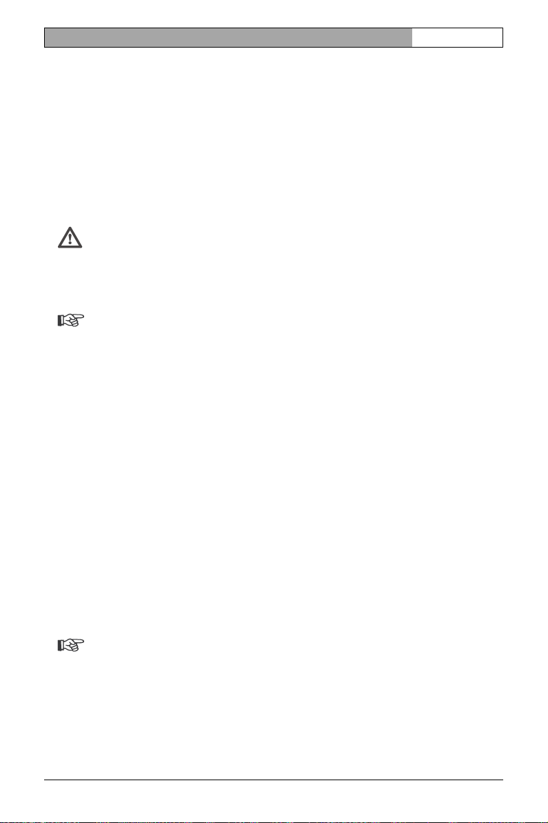
The stereo socket plugs must be connected as follows:
Contact Audio 1 to Audio 8 Audio Out
Tip Line Out Left channel
Middle ring Line In Right channel
Lower ring Ground Ground
– Connect the desired audio sources with line level to the Audio 1 to Audio 8
sockets with a 3.5 mm stereo plug.
– If necessary, connect two loudspeakers to the Audio Out socket.
If you wish to connect a microphone and a loudspeaker directly:
– Connect the microphone cords to the AI and ground connections on the
push-in terminal.
– Connect the loudspeaker cords to the AO and ground connections on the
push-in terminal.
Relay outputs (audio versions only)
The audio versions of VideoJet 8008 and VideoJet 8004 have five relay outputs
for connecting external units such as lamps or alarm sirens. You can operate
these relay outputs manually while there is an active connection to the device.
The output can also be configured to automatically activate sirens or other alarm
units in response to an alarm signal. The relay outputs are also located on the
orange terminal block.
Caution
A maximum load of 30 V and 2 A may be applied to the relay contacts.
– Connect the lines to the appropriate R1 to R5 terminals of the orange terminal
block and check that the connections are secure.
Second RS232 data interface (audio versions only)
The audio versions of VideoJet 8008 and VideoJet 8004 have a second serial
interface. The RS232 connection is designed as a 9-pin sub-D socket and supports the RS232 transmission standard.
Bosch Security Systems | 2006-07 | V1.5 Installation
Page 24
EN | 24
Installation and Operating Manual | VideoJet 8008 / VideoJet 8004
Power on/Power off
Power supply
The VideoJet 8008 and VideoJet 8004 are supplied with a power supply cable
and rubber connector. The units do not have a power switch. After you have connected the unit to the power supply and the unit has booted, it is ready for use.
Caution
Where necessary, use suitable equipment to ensure that the power supply
is free from interference such as voltage surges, spikes or voltage drops.
Caution
You should only connect the unit to the mains once all other connections
have been made.
– Plug the rubber connector of the power supply cable into the Power socket.
– Connect the power supply cable to a fused mains socket. The green Power
LED on the front panel of the unit lights up. As soon as the text VideoJet 8008
or VideoJet 8004 is displayed on the screen after the unit has booted, the unit
is ready for use.
If the network connection has been correctly set up, the green LED of the
10/100/1000 MBit Base-T RJ45 socket on the back of the unit is illuminated.
The flashing orange LED signals that data packets are being transmitted across
the network.
Installation Bosch Security Systems | 2006-07 | V1.5
Page 25
VideoJet 8008 / VideoJet 8004 | Installation and Operating Manual
EN | 25
Setup using a terminal program
Data terminal
You can connect a data terminal to the unit for setup and local control. The data
terminal consists of a computer with a terminal program. Use the configuration
cable supplied to establish the connection.
HyperTerminal, a communications accessory included with Microsoft Windows,
can be used as the terminal program.
Note
Information on installing and using HyperTerminal can be found in the
manuals or in the online help for MS Windows.
– Disconnect the unit from the data network before working with the terminal
program.
– Connect the unit's RS232/485 RJ45 socket to a free serial interface on the
computer.
Configuring the terminal
Before the terminal program can communicate with the unit, the transmission
parameters must be matched. Make the following settings for the terminal program:
❚ 19,200 bit/s
❚ 8 data bits
❚ No parity check
❚ 1 stop bit
❚ No protocol
Bosch Security Systems | 2006-07 | V1.5 Installation
Page 26
EN | 26
Installation and Operating Manual | VideoJet 8008 / VideoJet 8004
Command inputs
After the connection has been established, you must log onto the unit to access
the main menu. Other submenus and functions can be accessed using the
on-screen commands.
– If necessary, turn off the local echo so that entered values are not repeated
on the display.
– Enter one command at a time.
– When you have entered a value (such as an IP address), check the charac-
ters you have entered before pressing the [ENTER] key to transfer the values
to the unit.
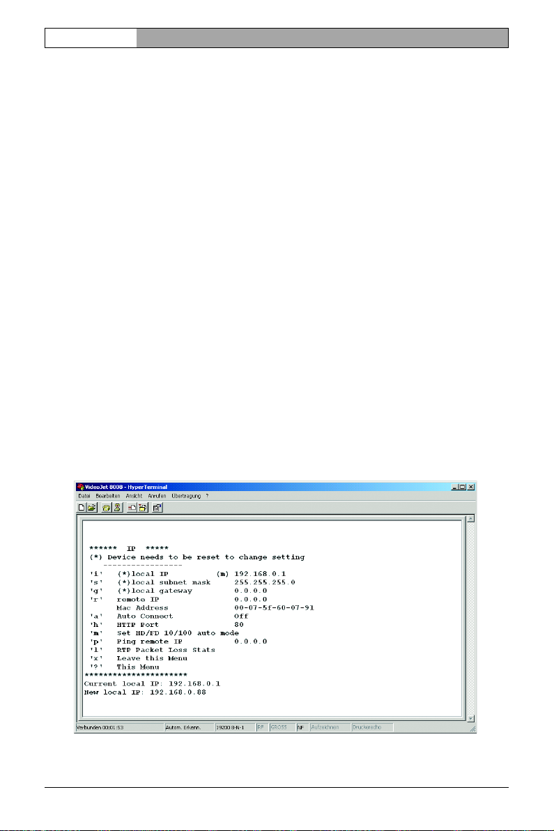
Assigning an IP Address
To use a VideoJet 8008 or VideoJet 8004 in your network, you must assign it an
IP address that is valid for your network.
The following default address is preset at the factory: 192.168.0.1
– Start a terminal program such as HyperTerminal.
–First enter ? and then service as the user name. The terminal program dis-
plays the main menu.
– Enter command i to open the IP menu.
Installation Bosch Security Systems | 2006-07 | V1.5
Page 27
VideoJet 8008 / VideoJet 8004 | Installation and Operating Manual
EN | 27
– Enter i again. The terminal program displays the current IP address and
prompts you to enter a new IP address.
– Enter the desired IP address and press [ENTER]. The terminal program dis-
plays the new IP address.
– If necessary, enter command s and a new subnet mask.
Note
You must restart to activate the new IP address, a new subnet mask or a
gateway address.
Restart
Briefly disconnect the power supply from the unit (unplug the power supply cable
and plug it in again after a few seconds).
Additional parameters
You can use the terminal program to check other basic parameters and modify
them where necessary. Use the on-screen commands in the various submenus
to do this.
Bosch Security Systems | 2006-07 | V1.5 Installation
Page 28

EN | 28
Installation and Operating Manual | VideoJet 8008 / VideoJet 8004
Installation Bosch Security Systems | 2006-07 | V1.5
Page 29
VideoJet 8008 / VideoJet 8004 | Installation and Operating Manual
EN | 29
Configuration using a Web browser 5
Connecting
The integrated HTTP server provides you with the option to configure the unit
over the network with a Web browser. This option is significantly more comprehensive and convenient than configuration using a terminal program and also
offers you the option of displaying live video images.
Note
Make sure the graphics card is set to 16- or 32-bit color depth and that Microsoft Virtual Machine is installed and activated on your PC. If necessary,
you can install the required software and controls from the product CD
supplied (see Components supplied, page 9).
Instructions for using the Web browser can be found in its online help.
System requirements
❚ Microsoft Internet Explorer (version 6.0 or higher)
❚ Monitor resolution 1024 × 768 pixels
❚ Network access (Intranet or Internet)
Note
Also note the information in the System Requirements document on the
product CD supplied.
Installing MPEG ActiveX
Note
Suitable MPEG ActiveX software must be installed on the computer to allow the live video images to be played back. If necessary, you can install
the required software and controls from the product CD supplied (see
Components supplied, page 9).
Bosch Security Systems | 2006-07 | V1.5 Configuration using a Web browser
Page 30
EN | 30
Installation and Operating Manual | VideoJet 8008 / VideoJet 8004
– Insert the CD into the computer's CD-ROM drive. If the CD does not start
automatically, open the root directory of the CD in Windows Explorer and
double click MPEGAx.exe.
– Follow the on-screen instructions.
Establishing the connection
To operate the unit in your network, it must have a valid IP address for your network.
The following default address is preset at the factory: 192.168.0.1
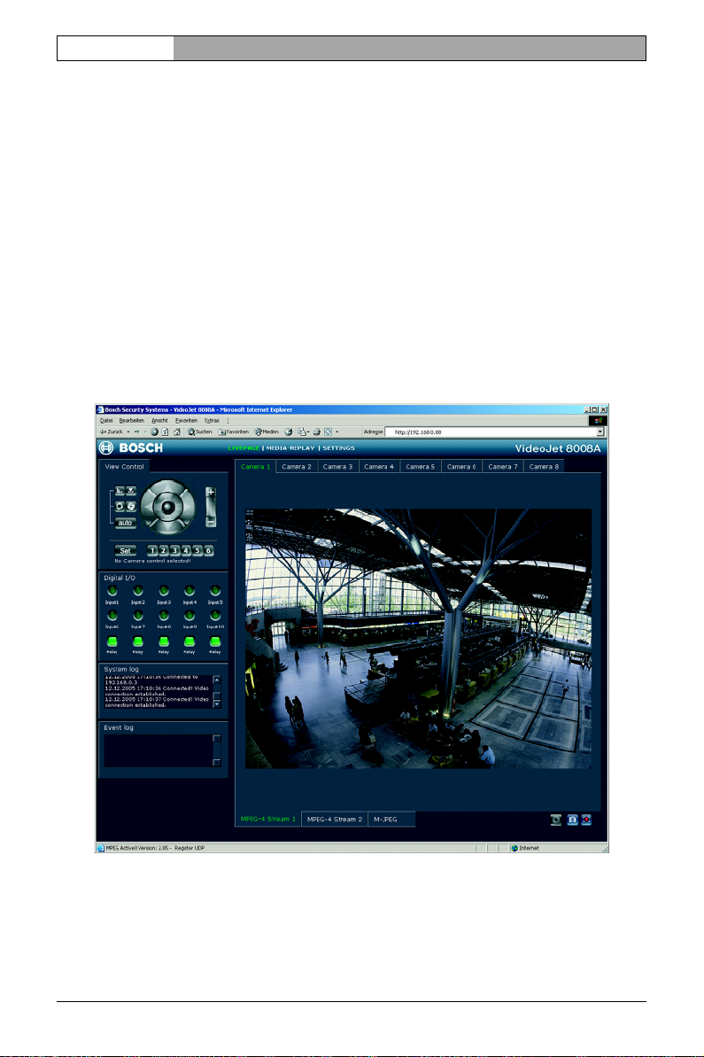
– Start the Web browser.
– Enter the unit's IP address as the URL. The connection is established and
after a short time you will see the LIVEPAGE with the video image.
Configuration using a Web browser Bosch Security Systems | 2006-07 | V1.5
Page 31

VideoJet 8008 / VideoJet 8004 | Installation and Operating Manual
EN | 31
Note
The screen display can differ from that shown above, depending on the
unit variants that you use.
If you do not connect, the device may have reached its maximum number of connections. The maximum number of connections depends on the unit and network configuration.
Protected unit
If the unit is password protected against unauthorized access, the Web browser
displays a message to that effect and prompts you to enter the password when
you call up access-protected areas.
Note
The unit offers the option of limiting access across various authorization
levels (see pages 48 and 65).
– Enter the user name and associated password in the corresponding text fields.
– Click OK. If the password is entered correctly, the Web browser displays the
page that was called up.
Choosing the configuration mode
There are two options for configuring the unit or checking the current settings:
❚ the unit overview or
❚ the configuration menu.
All settings are stored in the unit's memory so that they are retained even if the
power supply is interrupted.
Unit overview
The unit overview shows the most important parameters summarized into six
groups. This overview allows you to change the basic settings with just a few
clicks and entries.
Bosch Security Systems | 2006-07 | V1.5 Configuration using a Web browser
Page 32

EN | 32
Installation and Operating Manual | VideoJet 8008 / VideoJet 8004
Configuration menu
The configuration menu is recommended for expert users or system administrators. You can access all unit parameters in this mode. Settings that affect the
fundamental functioning of the unit (such as firmware updates) can only be
made using the configuration menu.
Starting configuration
Click the SETTINGS link in the upper section of the LIVEPAGE window.
The Web browser opens a new page containing the configuration menu (see
Configuration menu, page 63) and the unit overview (see Unit overview,
page 33):
Note
The screen display can differ from that shown above, depending on the
unit variants that you use.
Configuration using a Web browser Bosch Security Systems | 2006-07 | V1.5
Page 33

VideoJet 8008 / VideoJet 8004 | Installation and Operating Manual
EN | 33
Unit overview
The unit overview is a graphic presentation of the various areas of the configuration. The individual configuration parameters are arranged in groups and displayed in separate windows. You can access the individual areas directly.
– Click one of the graphic symbols. A new window will open.
– Click in the text fields to enter values or use the other controls that are avail-
able, such as buttons, checkboxes or list fields.
– Click the SETTINGS link at the top of the window to close the window without
saving the changes made.
Making changes
After making changes in a window, click the Set button to send the new settings
to the unit and to save them there.
Caution
Save the changes made in each window by clicking Set. If you click the
Set button, only the settings in the current window are saved.
The following sections describe the individual windows that can be accessed
using the graphic symbols in the unit overview.
Bosch Security Systems | 2006-07 | V1.5 Configuration using a Web browser
Page 34

EN | 34
Installation and Operating Manual | VideoJet 8008 / VideoJet 8004
Encoder settings
For encoding the video signal, you can select a profile for each camera, and for
Dual Streaming compatible units you can select two profiles each.
You can identify the Dual Streaming compatible units from the additional
MPEG-4 Stream 2 tab.
Selecting a profile
You can configure the MPEG-4 data transmission in accordance with the operating environment (for example network structure, bandwidth, data load). For
Dual Streaming compatible units, each encoder can create two data streams at
the same time, with different compression settings, such as for transmission and
local saving.
Note
The settings must be made individually for each camera input and stream.
The numbering is the same as the labeling of the video inputs on the rear
panel of the unit.
Pre-programmed profiles are available, each giving priority to different perspectives.
Configuration using a Web browser Bosch Security Systems | 2006-07 | V1.5
Page 35

VideoJet 8008 / VideoJet 8004 | Installation and Operating Manual
❚ Profile 1: Low bandwidth (CIF)
High quality for low bandwidth connections,
resolution 352 × 288/240 pixels
❚ Profile 2: Low delay (1/2 D1)
High quality with low delay,
resolution 352 × 576/480 pixels
❚ Profile 3: High resolution (D1/4CIF)
High resolution for high bandwidth connections,
resolution 704 × 576/480 pixels
❚ Profile 4: DSL
For DSL connections at 500 kBit/s,
resolution 352 × 288/240 pixels
❚ Profile 5: ISDN (2B)
For ISDN connections via two B channels,
resolution 352 × 288/240 pixels
❚ Profile 6: ISDN (1B)
For ISDN connections via one B channel,
resolution 352 × 288/240 pixels
❚ Profile 7: Modem
For analog modem connections at 20 kBit/s,
resolution 352 × 288/240 pixels
EN | 35
❚ Profile 8: GSM
For GSM connections at 9,600 baud,
resolution 176 × 144/120 pixels
Active profile for video 1 to Active profile for video 8:
Here, you can select the desired profile.
– Dual Streaming compatible units only: Click a tab to select the relevant stream.
– Select the desired setting from the list.
Note
Dual Streaming compatible units only: For alarm connections and automatic connections, stream 2 is always transmitted. Bear this fact in mind
when assigning the profile. Stream 2 is also used for local recording.
Bosch Security Systems | 2006-07 | V1.5 Configuration using a Web browser
Page 36

EN | 36
Installation and Operating Manual | VideoJet 8008 / VideoJet 8004
Note
When local recording is running, the profile set as the Recording profile
for the relevant video input is active (see page 45).
Changing profiles
You can change individual parameter values within a profile and you can also
change the name. You can switch between the profiles by clicking the appropriate tab.
Caution
The profiles are rather complex. They include a large number of parameters that interact with one another, so it is generally best to use the default
profiles. Change the profiles only once you are fully familiar with all the
configuration options.
Note
All parameters combine to make up a profile and are dependent on one
another. If you enter a parameter that is outside the permitted range, the
nearest permitted value will automatically be substituted when the settings
are saved.
Configuration using a Web browser Bosch Security Systems | 2006-07 | V1.5
Page 37

VideoJet 8008 / VideoJet 8004 | Installation and Operating Manual
EN | 37
Profile name:
You can enter a new name for the profile here. The name is then displayed in
the MPEG-4 encoder field in the list of selectable profiles.
Target data rate:
You can limit the data rate for the unit to optimize utilization of the bandwidth in
your network. The target data rate should be set according to the desired picture
quality for typical scenes with no excessive motion.
For complex images or frequent changes of image content due to frequent
movements, this limit can be temporarily exceeded up to the value you enter in
the Max. data rate field.
Max. data rate:
This maximum data rate is not exceeded under any circumstances. Depending
on the video quality settings for the I- and P-frames, this fact can result in individual images being skipped.
The value entered here should be at least 10% higher than the value entered in
the Target data rate field.
P-frame video quality:
This setting allows you to adjust the image quality of the P-frames depending on
the movement within the image. The Auto option automatically adjusts to the
optimum combination of movement and image definition (focus). Selecting Man-
ual allows you to set a value between 4 and 31 on the slide bar. The value
4 represents the best image quality with, if necessary, a lower frame refresh rate
depending on the settings for the maximum data rate. A value of 31 results in a
very high refresh rate and lower image quality.
I-frame video quality:
This setting allows you to adjust the image quality of the I-frames. The Auto
option automatically adjusts the quality to the settings for the P-frame video
quality. Selecting Manual allows you to set a value between 4 and 31 on the
slide bar. The value 4 represents the best image quality with, if necessary, a
lower frame refresh rate depending on the settings for the maximum data rate.
A value of 31 results in a very high refresh rate and lower image quality.
Bosch Security Systems | 2006-07 | V1.5 Configuration using a Web browser
Page 38

EN | 38
Installation and Operating Manual | VideoJet 8008 / VideoJet 8004
I-frame distance:
This parameter allows you to set the intervals in which the I-frames will be
coded. 0 means auto mode, whereby the video server inserts I-frames as necessary. An entry of 1 indicates that I-frames are continuously generated.
An entry of 2 indicates that only every second image is an I-frame, and 3 only
every third image etc.; the frames in between are coded as P-frames.
Encoding interval:
The figure selected here determines the interval at which images are encoded
and transmitted. For example, entering 4 means that only every fourth image is
encoded, the following three are skipped - this can be particularly advantageous
with low bandwidths.
Video resolution:
Here you can select the desired resolution for the MPEG-4 video image.
The following resolutions are available:
❚ QCIF 176 × 144/120 pixels
❚ CIF 352 × 288/240 pixels
❚ 1/2 D1 352 × 576/480 pixels
❚ 2CIF 704 × 288/240 pixels
❚ D1/4CIF 704 × 576/480 pixels
Reset of profile:
Click Default to return the profile to the factory default values.
Configuration using a Web browser Bosch Security Systems | 2006-07 | V1.5
Page 39

VideoJet 8008 / VideoJet 8004 | Installation and Operating Manual
EN | 39
Recording parameters
Here, you can set all parameters for recording on the local hard drive. Recording
can be performed continuously or only in the case of an alarm.
Partition:
Select the partition in which you want to record. Recording is performed for
every video input in a separate partition.
Activating a partition for recording
After configuration, you can activate the partition for recording by clicking the
Start button.
Bosch Security Systems | 2006-07 | V1.5 Configuration using a Web browser
Page 40

EN | 40
Installation and Operating Manual | VideoJet 8008 / VideoJet 8004
After starting, the Time recording, Alarm recording and Properties pages for the
activated partition are displayed in gray and the configuration cannot be modified.
The graphic in the lower section of the pages indicates this partition's recording
activity. You will see an animated graphic while recording is taking place.
You can terminate recording at any time and deactivate one, multiple or all partitions.
– Click the Start button to activate the currently selected partition for recording.
– Click the Start all button to activate all the partitions set up for the recording.
– Click the Stop button to deactivate the currently selected partition for record-
ing. Recordings that are currently running will be interrupted and the configuration can be modified.
– Click the Stop all button to deactivate all the partitions set up for the record-
ing. Running recordings are interrupted and the configuration can be
changed.
Time recording
You can specify the times during which continuous recording to the hard drive
should take place.
Separate selection fields per partition are available for each day of the week,
allowing settings to be made per camera input. You can select up to 16 individual
recording time intervals for each day of the week.
Note
If a period is already selected for alarm recording, you cannot select it for
time recording (see Alarm recording, page 42).
– Left-click the point in the schedule at which recording should start and hold
the button down.
– Drag the selected field to the desired recording end and then release the
mouse key.
– Right-click a highlighted time interval to delete it.
– Click the Select all button to highlight all time intervals.
– Click the Clear button to delete all highlighted time intervals.
Configuration using a Web browser Bosch Security Systems | 2006-07 | V1.5
Page 41

VideoJet 8008 / VideoJet 8004 | Installation and Operating Manual
EN | 41
Used filetracks on partition:
Within a partition, up to 128 filetracks are created automatically. Each new
recording has its own track.
In Linear mode (see page 45), no more new recordings are made when the
128 tracks are written; old recordings must first be deleted. In Ring mode,
the 129th recording is written in the first track again etc., so that the oldest
recording is overwritten with the most recent recording.
Used space on partition:
This displays how much space is already used in the partition.
Free space on partition:
This displays how much space is still available in the partition.
Recording status:
The graphic indicates the recording activity in this partition. You will see an animated graphic while recording is taking place.
Bosch Security Systems | 2006-07 | V1.5 Configuration using a Web browser
Page 42

EN | 42
Alarm recording
Installation and Operating Manual | VideoJet 8008 / VideoJet 8004
Here, you can specify the times during which continuous recording to the hard
drives should take place in the event of an alarm.
As with time recording, there are separate selection fields for each partition and
thus for each camera input. You can select up to 16 separate periods for each day
of the week. Alarm recording occurs only during the highlighted time intervals.
Note
If a period is already selected for time recording, you cannot select it for
alarm recording (see Time recording, page 40).
Caution
Alarm tracks must be set up in the required partition for alarm recording
(see Number of alarm tracks, page 43).
The unit uses a special recording mode during alarm recording for optimal usage
of storage capacity: as soon as a time gap for alarm recording begins, a recording is continuously made on one segment, which is the size of a complete alarm
sequence (pre- and post-alarm time).
Configuration using a Web browser Bosch Security Systems | 2006-07 | V1.5
Page 43

VideoJet 8008 / VideoJet 8004 | Installation and Operating Manual
EN | 43
This segment in the partition functions in a similar manner to a ring buffer and is
overwritten until an alarm is actually triggered. Recording occurs on the segment
only for the duration of the preset post-alarm time and a new segment subsequently used in the same manner.
This ensures that the alarm recorded is always secured for its entire duration
and the space required to save each alarm recording is easy to calculate.
Number of alarm tracks:
Select the number of alarm tracks to be used in the partition. One alarm event
can be recorded in each alarm track. Accordingly, the number of alarms entered
can be recorded and archived. A partition can contain a maximum of 128 alarm
recordings.
If the Ring mode option (see page 45) is set for the partition, the latest alarm
recordings are always saved in the preset number. If the Linear mode option is
set for the partition, the recording stops as soon as all the alarm tracks have
been written.
Pre-alarm duration:
Select the period to be covered by pre-alarm recording.
Post-alarm duration:
Select the period to be covered by alarm recording.
Used alarm tracks on partition:
This displays how many of the alarm tracks created have already been used.
Used space on partition:
This displays how much space is already used in the partition.
Free space on partition:
This displays how much space is still available in the partition.
Recording status:
The graphic indicates the recording activity in this partition. You will see an animated graphic while recording is taking place.
Bosch Security Systems | 2006-07 | V1.5 Configuration using a Web browser
Page 44

EN | 44
Properties
Installation and Operating Manual | VideoJet 8008 / VideoJet 8004
You can view the current properties for the partition selected in each case
directly in the recording scheduler and modify them if necessary. You can also
activate the alarms that should trigger recording. Similarly, you can also select
the profile for recording.
Configuration using a Web browser Bosch Security Systems | 2006-07 | V1.5
Page 45

VideoJet 8008 / VideoJet 8004 | Installation and Operating Manual
EN | 45
Caution
All modifications result in the reorganization of the partition and the loss of
all sequences on this partition.
Consequently, you should back up all important sequences on the computer's hard drive.
Partition name:
You can enter a new name for the partition.
Video input:
The number of the associated video input and the stream used for the recording
are displayed here. The numbering is the same as the labeling of the video
inputs on the rear panel of the unit.
Note
On Dual Streaming compatible units, stream 2 is always used for the recording.
Type of recording:
Select the required recording type.
In the case of Ring mode the recording proceeds continuously. If the maximum
hard drive space has been reached, the oldest recordings are automatically
overwritten.
In the case of
Linear mode
the recording proceeds until the entire hard drive
space is full. The recording is then stopped until old recordings have been deleted.
Video recording:
The recording format is displayed here for information.
Recording profile:
Select the profile that is to be active during recording. You can view and modify
the properties for the profiles (see Encoder settings, from page 34).
Note
The recording profile can differ from the standard setting Active profile for
the video input set and is only used during an active recording.
Bosch Security Systems | 2006-07 | V1.5 Configuration using a Web browser
Page 46

EN | 46
Installation and Operating Manual | VideoJet 8008 / VideoJet 8004
Alarm recording at:
You can select the alarm sensor that is to trigger a recording. You can also use
the motion and video alarm for a camera to trigger the alarm recording by
another camera.
Note
The alarm sensor must be active to be able to trigger the recording. The
alarm inputs and video loss alarms are activated on the Alarm settings
page (see page 51). The motion alarms are configured and activated for
each camera on the Motion detector page (see page 99).
– Check the box for the alarm sensor that is to trigger a recording. The selected
check boxes are marked with a tick.
Note
The numbers of the alarm input check boxes correspond to the labeling of
the alarm inputs on the rear panel of the unit. The motion and video loss
alarm numbers correspond to the labeling of the video inputs.
Partition total size:
This displays how much storage space the partition occupies on the hard drive.
Remaining for recording:
This displays the maximum remaining recording time. The value is automatically
updated after the parameters have been modified.
Free space on partition:
This displays how much space is still available in the partition.
Recording status:
The graphic indicates the recording activity in this partition. You will see an animated graphic while recording is taking place.
Format
You can delete all recordings in a partition at any time.
Caution
Check the recordings before deleting and back up important sequences on
the computer's hard drive.
–Click the
Configuration using a Web browser Bosch Security Systems | 2006-07 | V1.5
Format
button to delete all recordings on the currently selected partition.
Page 47

VideoJet 8008 / VideoJet 8004 | Installation and Operating Manual
EN | 47
System settings
Here you can set or select various basic data for the unit.
Unit identification
Unit name:
You can give the unit a name to make it easier to identify. The name simplifies
the management of multiple units in larger systems, for example using the
VIDOS program.
Note
The unit name is used for the remote identification of a unit, in the event of
an alarm, for example, or to make it easier to call up a unit when using a
DNS server. Enter a name that makes it as easy as possible to quickly
identify the location.
Unit ID:
Every unit should be assigned a unique identifier that you enter here as an additional means of identification.
Bosch Security Systems | 2006-07 | V1.5 Configuration using a Web browser
Page 48

EN | 48
Installation and Operating Manual | VideoJet 8008 / VideoJet 8004
Password
A unit is generally protected by a password to prevent unauthorized access to
the unit. You can use different authorization levels to limit access.
Note
Proper password protection is only guaranteed when all higher authorization levels are also protected with a password. If a live password is assigned, for example, a service and a user password must also be set.
When assigning passwords, you should therefore always start from the
highest authorization level.
User name:
The unit operates with three user names: service, user and live, which correspond to different authorization levels.
The service user name is the highest authorization level. After entering the correct password, this user name allows you to use all the functions of the unit and
change all configuration settings.
The user user name is the middle authorization level. You use it to operate the
unit and also to control cameras, for example, but you cannot change the configuration.
The live user name is the lowest authorization level. It can only be used to view
the live video image and switch between the different live image displays.
Password:
You can define and change a separate password for each user name if you are
logged in as service or if the unit is not password protected.
Enter the password for the selected user name here.
Configuration using a Web browser Bosch Security Systems | 2006-07 | V1.5
Page 49

VideoJet 8008 / VideoJet 8004 | Installation and Operating Manual
Confirm password:
Enter the new password a second time to eliminate typing mistakes.
Note
The new password is only saved when you click the Set button. You
should therefore click the Set button immediately after entering and confirming the password, even if you also wish to subsequently assign a password to another user name.
Language
Website language:
Select the language for the user interface here.
Date and time
EN | 49
Date format:
Select your required date format
(Europe: DD.MM.YYYY; USA: MM.DD.YYYY; Japan: YYYY/MM/DD).
Bosch Security Systems | 2006-07 | V1.5 Configuration using a Web browser
Page 50

EN | 50
Installation and Operating Manual | VideoJet 8008 / VideoJet 8004
Unit date and Unit time:
If there are multiple devices operating in your system or network, it is important
to synchronize their internal clocks. For example, it is only possible to identify
and correctly evaluate simultaneous recordings when all units are operating on
the same time.
– Enter the current date. Since the unit time is controlled by the internal clock,
there is no need to enter the day of the week - it is added automatically.
– Enter the current time or click the Synchr. PC button to copy your computer's
system time to the unit.
Version information
The hardware and firmware version numbers are for information only and cannot
be changed. Keep a record of these numbers in case technical assistance is
required.
Hardware version:
The hardware version number of the unit is displayed.
Firmware version:
The firmware version number of the unit is displayed.
Configuration using a Web browser Bosch Security Systems | 2006-07 | V1.5
Page 51

VideoJet 8008 / VideoJet 8004 | Installation and Operating Manual
EN | 51
Alarm settings
In this option you can make your settings for the alarm sources and alarm connections.
Alarm sources
You can configure the possible alarm triggers for the unit (for example, the alarm
inputs).
Alarm input 1 to Alarm input 10:
Select the On option to activate the alarm by the corresponding external alarm
sensor. Otherwise, select Off.
Select Active high if the alarm is to be triggered by closing the contact. Select
Active low if the alarm is to be triggered by opening the contact.
Bosch Security Systems | 2006-07 | V1.5 Configuration using a Web browser
Page 52

EN | 52
Installation and Operating Manual | VideoJet 8008 / VideoJet 8004
Name:
You can enter a name for each alarm input, which is then displayed below the
icon for the alarm input on the LIVEPAGE if configured correctly
(see Livepage configuration, page 112).
Video loss alarm:
Activate the checkbox if you want an interruption of the video signal to trigger an
alarm. A selected video input is indicated by a check mark.
Note
The numbering is the same as the labeling of the video inputs on the rear
panel of the unit.
1. SNMP host address / 2. SNMP host address:
The unit supports the SNMP (Simple Network Management Protocol) for managing and monitoring network components and can send SNMP messages to
IP addresses. It supports SNMP MIB II and its traps in their full functionality in
the unified code. If you wish to send SNMP traps, enter the IP addresses of one
or two required target devices here. UDP Port 161 is generally used as the port
for the SNMP functionalities.
Configuration using a Web browser Bosch Security Systems | 2006-07 | V1.5
Page 53

VideoJet 8008 / VideoJet 8004 | Installation and Operating Manual
EN | 53
Alarm connections
You can select how the unit responds to an alarm. In the event of an alarm, the
unit can automatically connect to a pre-defined IP address. You can enter up to
ten IP addresses to which the unit will connect in sequence in the event of an
alarm, until a connection is made. You can also select which camera image
should automatically be shown first on the receiver in the event of an alarm.
Connect on alarm:
Select On so that the unit automatically connects to a predefined IP address in
the event of an alarm.
Note
Dual Streaming compatible units only: Stream 2 is always transferred for
alarm connections. Bear this fact in mind when assigning the profile
(see page 34).
Number of destination IP address:
Specify the numbers of the IP addresses to be contacted in the event of an
alarm. The unit contacts the remote stations one after the other in the numbered
sequence until a connection is made.
Destination IP address:
For each number, enter the corresponding IP address for the desired remote
station.
Destination password:
If the remote station is password protected, enter the password here.
Bosch Security Systems | 2006-07 | V1.5 Configuration using a Web browser
Page 54

EN | 54
Installation and Operating Manual | VideoJet 8008 / VideoJet 8004
Auto-connect:
Select the On option to automatically re-establish a connection to one of the
previously specified IP addresses after each restart, after a connection breakdown or after a network failure.
Note
Dual Streaming compatible units only: Stream 2 is always transferred for
alarm connections. Bear this fact in mind when assigning the profile
(see page 34).
Default camera:
Here you can select the camera whose image will be automatically displayed
first on the receiver when the alarm connection is made. Depending on the system configuration, the receiver can then select the other cameras as well.
Note
The numbering is the same as the labeling of the video inputs on the rear
panel of the unit.
Configuration using a Web browser Bosch Security Systems | 2006-07 | V1.5
Page 55

VideoJet 8008 / VideoJet 8004 | Installation and Operating Manual
EN | 55
Network settings
Here you can specify network addresses and configure multiple connections.
Network
The settings in this screen are used to integrate the unit into an existing network.
Caution
Changes to the IP address, subnet mask or gateway address are transferred to the unit by clicking Set. However, they only take effect after the
unit is restarted.
– Click Set after entering a new IP address.
– Enter the old IP address followed by /reset (for example
192.168.0.88/reset) in your Web browser's address bar. The unit restarts
and can then only be accessed at the new IP address.
Unit IP address:
Enter the desired IP address for the unit. The IP address must be valid for the
network.
Subnet mask:
Enter the appropriate subnet mask for the selected IP address here.
Bosch Security Systems | 2006-07 | V1.5 Configuration using a Web browser
Page 56

EN | 56
Installation and Operating Manual | VideoJet 8008 / VideoJet 8004
Gateway IP address:
If you want the unit to establish a connection to a remote location in a different
subnet, enter the IP address of the gateway here. Otherwise leave the box blank
(0.0.0.0).
Ethernet link type:
If the unit is connected to the network via a switch, both must have the same
default for the type of network connection. If necessary, ask your network administrator what value the switch is set to.
The Auto setting automatically detects the network connection. If necessary,
you can specify the value 10 or 100 MBit/s for full or half-duplex mode (FD or
HD) or 1 GBit/s FD.
Caution
Malfunctions such as image faults can occur if the network does not have
enough capacity to transmit the maximum data rate generated by the unit.
Dynamic DNS server IP address:
When operating a unit on the Internet, dynamic addresses are used to ensure
efficient use of the available IP address pool. That is, the unit is reassigned a
(changing) IP address each time a new connection is made. Access is easier if
the unit is listed in a DNS server. It registers there at regular intervals and leaves
the unit name and its IP address. If you wish to establish an Internet connection
to a unit, it is sufficient to enter the appropriate unit name together with the URL
of the DNS server. This then reports on the current Internet IP address used to
establish the connection.
Dynamic DNS contact interval:
Enter the desired refresh interval in seconds here.
Configuration using a Web browser Bosch Security Systems | 2006-07 | V1.5
Page 57

VideoJet 8008 / VideoJet 8004 | Installation and Operating Manual
EN | 57
Multicasting
In addition to a 1:1 connection between an encoder and a single receiver (unicast), the unit can enable multiple receivers to receive the video signal from an
encoder simultaneously. The device either duplicates the data stream itself and
then distributes it to multiple receivers (Multi-unicast) or it sends a single data
stream to the network, where the data stream is simultaneously distributed to
multiple receivers in a defined group (Multicast). For each of the eight encoders,
you can enter a separate multicast address and the relevant port for each
stream.
For Dual Streaming compatible units, you can toggle between the streams by
clicking the appropriate tab pages.
Note
Multicast operation requires a multicast-enabled network that uses the
UDP and the Internet Group Management IGMP protocols. Other group
management protocols are not supported. The TCP protocol does not support multicast connections.
A special IP address (class D address) must be configured for multicast operation in a multicast-enabled network.
The network must support group IP addresses and the Internet Group Management Protocol (IGMP V2). The address range is 224.0.1.0 to 239.255.255.255.
Bosch Security Systems | 2006-07 | V1.5 Configuration using a Web browser
Page 58

EN | 58
Installation and Operating Manual | VideoJet 8008 / VideoJet 8004
The multicast address can be the same for multiple streams. However, it will be
necessary to use a different port in each case so that multiple data streams are
not sent simultaneously using the same port and multicast address.
Note
The settings must be made individually for each video input and, on
Dual Streaming compatible units, for each stream. The numbering is the
same as the labeling of the video inputs on the rear panel of the unit.
Multicast address video 1 to Multicast address video 8:
Enter a valid multicast address for each stream from the relevant encoder to be
operated in multicast mode (duplication of the data streams in the network).
With the setting 0.0.0.0 the encoder for the relevant stream operates in multi-unicast mode (copying of data streams in the unit). The unit supports multi-unicast
connections for up to five simultaneously connected receivers.
Note
Duplication of data places a heavy demand on the unit and can lead to impairment of the image quality under certain circumstances.
Multicast port 1 to Multicast port 8:
Assign a different port to each data stream if there are simultaneous data
streams at the same multicast address.
Enter the port address of the required stream here.
Streaming:
Click the checkbox to activate multicast streaming mode for the relevant stream.
The selected check boxes are marked with a tick.
Multicast packet TTL:
You can enter a value to specify how long the multicast data packets are active
on the network. This value must be greater than one if multicast is to be run via
a router.
Multicast address audio: (audio versions only)
For special applications, you can enter a separate multicast address for the
audio data stream.
Configuration using a Web browser Bosch Security Systems | 2006-07 | V1.5
Page 59

VideoJet 8008 / VideoJet 8004 | Installation and Operating Manual
Note
Audio signals are only transmitted if the audio function is activated on the
Audio Stream configuration page (see page 78).
Multicast port 1: (audio versions only)
Enter the port address of the separate audio stream here.
EN | 59
Bosch Security Systems | 2006-07 | V1.5 Configuration using a Web browser
Page 60

EN | 60
Installation and Operating Manual | VideoJet 8008 / VideoJet 8004
COM settings
You can configure the parameters of the RS232/485 serial interface to meet
your requirements. On audio versions, you can also configure the parameters of
the second RS232 serial interface.
COM1
Note
If the unit is working in multicast mode (see page 57 onward), the first remote location to establish a video connection to the unit is also assigned
the transparent data connection. However, after about 15 seconds of inactivity the data connection is automatically terminated and another remote
location can exchange transparent data with the unit.
Serial port function:
Select a controllable unit from the list. If you wish to use the serial port to transmit
transparent data, select Transparent. Select Terminal if you wish to operate
the unit from a terminal.
Note
After selecting a unit, the remaining parameters in the window are set automatically and should not be changed.
Configuration using a Web browser Bosch Security Systems | 2006-07 | V1.5
Page 61

VideoJet 8008 / VideoJet 8004 | Installation and Operating Manual
EN | 61
Camera ID:
If necessary, enter the ID of the peripheral you wish to control (for example a
dome camera or pan/tilt head).
Note
If you are using a Bosch AutoDome, remember that the value of the Camera ID must always be selected one less than the Bosch camera number
(for example: Bosch camera number: 1, Camera ID: 0).
Baud rate:
Select the value for the transmission rate in bit/s.
Data bits:
The number of data bits per character cannot be changed.
Stop bits:
Select the number of stop bits per character.
Parity check:
Select the type of parity check.
Interface mode:
Select the desired protocol for the serial interface.
Half-duplex mode:
Choose the setting appropriate for your application.
Bosch Security Systems | 2006-07 | V1.5 Configuration using a Web browser
Page 62

EN | 62
Installation and Operating Manual | VideoJet 8008 / VideoJet 8004
COM2 (audio versions only)
Serial port function:
Select the desired function from the list. If you wish to use the additional
RS232 serial interface (9-pin sub-D socket) to transmit transparent data, select
Transparent. Select Terminal if you wish to operate the unit from a terminal.
Baud rate:
Select the value for the transmission rate in bit/s.
Data bits:
The number of data bits per character cannot be changed.
Stop bits:
Select the number of stop bits per character.
Parity check:
Select the type of parity check.
Configuration using a Web browser Bosch Security Systems | 2006-07 | V1.5
Page 63

VideoJet 8008 / VideoJet 8004 | Installation and Operating Manual
EN | 63
Configuration menu
The configuration menu allows you to configure all parameters of the unit. You
can view the current settings by opening one of the configuration screens. You
can change the settings by entering new values or by selecting a predefined
value from a list field.
Navigation
You see the configuration menu as well as the unit overview when you click the
SETTINGS link on the LIVEPAGE.
– Click one of the menu items in the left-hand margin of the window.
The associated submenu opens.
Note
The screen display can differ from that shown above, depending on the
unit variants that you use.
– Click one of the links in the submenu. The Web browser opens the corre-
sponding page.
Bosch Security Systems | 2006-07 | V1.5 Configuration using a Web browser
Page 64

EN | 64
Installation and Operating Manual | VideoJet 8008 / VideoJet 8004
Making changes
Each configuration screen shows the current settings. You can change the settings by entering new values or by selecting a predefined value from a list field.
– After each change, click Set to save the change.
Caution
Save each change with the associated Set button. Clicking the Set button
saves the settings only in the current field. Changes in any other fields are
ignored.
Unit identification
You can give the unit a name and ID to make it easier to identify. They both simplify the management of multiple units in larger systems, for example using the
VIDOS program.
Unit name:
Enter a name for the unit here.
Note
The unit name is used for the remote identification of a unit, in the event of
an alarm, for example, or to make it easier to call up a unit when using a
DNS server. Enter a name that makes it as easy as possible to quickly
identify the location.
Unit ID:
Every unit should be assigned a unique identifier that you enter here as an additional means of identification.
Configuration using a Web browser Bosch Security Systems | 2006-07 | V1.5
Page 65

VideoJet 8008 / VideoJet 8004 | Installation and Operating Manual
EN | 65
Password
A unit is generally protected by a password to prevent unauthorized access to the
unit. You can use different authorization levels to limit access.
Note
Proper password protection is only guaranteed when all higher authorization levels are also protected with a password. If a live password is assigned, for example, a service and a user password must also be set.
When assigning passwords, you should therefore always start from the
highest authorization level.
User name:
The unit operates with three user names: service, user and live, which correspond to different authorization levels.
The service user name is the highest authorization level. After entering the correct password, this user name allows you to use all the functions of the unit and
change all configuration settings.
The user user name is the middle authorization level. You use it to operate the
unit and also to control cameras, for example, but you cannot change the configuration.
The live user name is the lowest authorization level. It can only be used to view
the live video image and switch between the different live image displays.
Password:
You can define and change a separate password for each user name if you are
logged in as service or if the unit is not password protected.
Enter the password for the selected user name here.
Bosch Security Systems | 2006-07 | V1.5 Configuration using a Web browser
Page 66

EN | 66
Installation and Operating Manual | VideoJet 8008 / VideoJet 8004
Confirm password:
Enter the new password a second time to eliminate typing mistakes.
Note
The new password is only saved when you click the Set button. You
should therefore click the Set button immediately after entering and confirming the password, even if you also wish to subsequently assign a password to another user name.
Language
You can select the language of the user interface to make the unit easier to use.
Website language:
Select the desired language here.
Date and time
If there are multiple devices operating in your system or network, it is important
to synchronize their internal clocks. For example, it is only possible to identify
and correctly evaluate simultaneous recordings when all units are operating on
the same time.
Date format:
Select your required date format.
(Europe: DD.MM.YYYY; USA: MM.DD.YYYY; Japan: YYYY/MM/DD).
Unit date:
Enter the current date. Since the unit time is controlled by the internal clock,
there is no need to enter the day of the week - it is added automatically.
Configuration using a Web browser Bosch Security Systems | 2006-07 | V1.5
Page 67

VideoJet 8008 / VideoJet 8004 | Installation and Operating Manual
EN | 67
Unit time:
Enter the current time or click the Synchr. PC button to copy your computer's
system time to the unit.
Time server
The unit can receive the time signal of a time server via the Time Server Protocol
(RFC 868) and set the internal clock accordingly. The unit polls the time signal
automatically every ten minutes.
Time zone:
Select the time zone in which your system is located.
Time settings:
Check this box during daylight saving time to include the time change. Deactivate the box again to return to winter time.
Time server IP address:
Enter the IP address of a time server that uses the RFC 868 protocol.
Bosch Security Systems | 2006-07 | V1.5 Configuration using a Web browser
Page 68

EN | 68
Installation and Operating Manual | VideoJet 8008 / VideoJet 8004
Camera names
The camera name makes it easier to identify the remote camera location, in the
event of an alarm for example. It will be displayed in the video screen if configured to do so (see page 69). The camera name is also used by VIDOS, the program for managing video surveillance systems, and makes it easier to identify
the camera there.
Camera 1 to Camera 8:
Enter a unique and clear description as the camera name.
Note
The numbering is the same as the labeling of the video inputs on the rear
panel of the unit.
Configuration using a Web browser Bosch Security Systems | 2006-07 | V1.5
Page 69

VideoJet 8008 / VideoJet 8004 | Installation and Operating Manual
EN | 69
Display stamping
Various overlays or “stamps” in the video image provide important supplementary information. These overlays can be enabled individually and are arranged
on the image in a clear manner.
Note
The settings on this page apply to all camera inputs.
Camera name stamping:
This field sets the position of the camera name overlay. It can be displayed at
the Top, at the Bottom or at a position of your choice that you can then specify
using the Custom option. Or it can be set to Off for no overlay information.
Time stamping:
This field sets the position of the time overlay. It can be displayed at the Top,
Bottom or at a position of your choice that you have previously defined via
HyperTerminal using the Custom option. Or it can be set to Off for no overlay
information.
Alarm mode stamping:
Choose On to display a text message overlay in the event of an alarm. It can be
displayed at a position of your choice that you can then specify using the Cus-
tom option. Or it can be set to Off for no overlay information.
– Select the desired position from the lists.
– If you select the Custom option, additional fields are displayed where you
can specify the exact position (Position (XY):).
– In the Position (XY): fields enter the values for the desired position.
Bosch Security Systems | 2006-07 | V1.5 Configuration using a Web browser
Page 70

EN | 70
Installation and Operating Manual | VideoJet 8008 / VideoJet 8004
Displayed alarm message:
Enter the message to be displayed for an alarm. The maximum text length is
31 characters.
Video watermarking:
Choose On if you wish the transmitted video images to be “watermarked”. After
activation, all images are marked with a small green rectangle. A red rectangle
indicates that the sequence (live or saved) has been manipulated.
Configuration using a Web browser Bosch Security Systems | 2006-07 | V1.5
Page 71

VideoJet 8008 / VideoJet 8004 | Installation and Operating Manual
EN | 71
Picture settings
You can set the video image of each camera to suit your requirements. The current video image is displayed in the small window next to the slide controls as
confirmation. Your changes are effective immediately.
– Click a tab to select the corresponding camera.
– Set the slide bar to the desired position.
– Click Default to reset all settings to their default value.
Contrast (0...255):
You can use this function to adapt the contrast of the video image to your working environment.
Saturation (0...255):
You can use this function to adjust the color saturation so as to make the reproduction of colors on your monitor as realistic as possible.
Brightness (0...255):
You can use this function to adapt the brightness of the video image to your
working environment.
Bosch Security Systems | 2006-07 | V1.5 Configuration using a Web browser
Page 72

EN | 72
Installation and Operating Manual | VideoJet 8008 / VideoJet 8004
MPEG-4 encoder
For encoding the video signal, you can select a profile for each camera, and for
Dual Streaming compatible units you can select two profiles each.
You can identify the Dual Streaming compatible units from the additional
MPEG-4 Stream 2 tab.
Selecting a profile
You can configure the MPEG-4 data transmission in accordance with the operating environment (for example network structure, bandwidth, data load). For
Dual Streaming compatible units, each encoder can create two data streams at
the same time, with different compression settings, such as for transmission and
local saving.
Note
The settings must be made individually for each camera input and stream.
The numbering is the same as the labeling of the video inputs on the rear
panel of the unit.
Pre-programmed profiles are available, each giving priority to different perspectives.
❚ Profile 1: Low bandwidth (CIF)
High quality for low bandwidth connections,
resolution 352 × 288/240 pixels
❚ Profile 2: Low delay (1/2 D1)
High quality with low delay,
resolution 352 × 576/480 pixels
Configuration using a Web browser Bosch Security Systems | 2006-07 | V1.5
Page 73

VideoJet 8008 / VideoJet 8004 | Installation and Operating Manual
❚ Profile 3: High resolution (D1/4CIF)
High resolution for high bandwidth connections,
resolution 704 × 576/480 pixels
❚ Profile 4: DSL
For DSL connections at 500 kBit/s,
resolution 352 × 288/240 pixels
❚ Profile 5: ISDN (2B)
For ISDN connections via two B channels,
resolution 352 × 288/240 pixels
❚ Profile 6: ISDN (1B)
For ISDN connections via one B channel,
resolution 352 × 288/240 pixels
❚ Profile 7: Modem
For analog modem connections at 20 kBit/s,
resolution 352 × 288/240 pixels
❚ Profile 8: GSM
For GSM connections at 9600 baud,
resolution 176 × 144/120 pixels
Active profile for video 1 to Active profile for video 8:
EN | 73
Here, you can select the desired profile.
– Dual Streaming compatible units only: Click a tab to select the relevant
stream.
– Select the desired setting from the list.
Note
Dual Streaming compatible units only: For alarm connections and automatic connections, stream 2 is always transmitted. Bear this fact in mind
when assigning the profile. Stream 2 is also used for local recording.
Note
When local recording is running, the profile set as the recording profile
for the relevant video input is active (see page 45).
Bosch Security Systems | 2006-07 | V1.5 Configuration using a Web browser
Page 74

EN | 74
Installation and Operating Manual | VideoJet 8008 / VideoJet 8004
Changing profiles
You can change individual parameter values within a profile and you can also
change the name. You can switch between the profiles by clicking the appropriate tab.
Caution
The profiles are rather complex. They include a large number of parameters that interact with one another, so it is generally best to use the default
profiles. Change the profiles only once you are fully familiar with all the
configuration options.
Note
All parameters combine to make up a profile and are dependent on one
another. If you enter a parameter that is outside the permitted range, the
nearest permitted value will automatically be substituted when the settings
are saved.
Profile name:
You can enter a new name for the profile here. The name is then displayed in
the MPEG-4-Encoder field in the list of selectable profiles.
Configuration using a Web browser Bosch Security Systems | 2006-07 | V1.5
Page 75

VideoJet 8008 / VideoJet 8004 | Installation and Operating Manual
EN | 75
Target data rate:
You can limit the data rate for the unit to optimize utilization of the bandwidth in
your network. The target data rate should be set according to the desired picture
quality for typical scenes with no excessive motion.
For complex images or frequent changes of image content due to frequent
movements, this limit can be temporarily exceeded up to the value you enter in
the Max. data rate field.
Max. data rate:
This maximum data rate is not exceeded under any circumstances. Depending
on the video quality settings for the I- and P-frames, this fact can result in individual images being skipped.
The value entered here should be at least 10% higher than the value entered in
the Target data rate field.
P-frame video quality:
This setting allows you to adjust the image quality of the P-frames depending on
the movement within the image. The Auto option automatically adjusts to the
optimum combination of movement and image definition (focus). Selecting
Manual allows you to set a value between 4 and 31 on the slide bar. The value
4 represents the best image quality with, if necessary, a lower frame refresh rate
depending on the settings for the maximum data rate. A value of 31 results in a
very high refresh rate and lower image quality.
I-frame video quality:
This setting allows you to adjust the image quality of the I-frames. The Auto
option automatically adjusts the quality to the settings for the P-frame video
quality. Selecting Manual allows you to set a value between 4 and 31 on the
slide bar. The value 4 represents the best image quality with, if necessary, a
lower frame refresh rate depending on the settings for the maximum data rate.
A value of 31 results in a very high refresh rate and lower image quality.
I-frame distance:
This parameter allows you to set the intervals in which the I-frames will be
coded. 0 means auto mode, whereby the video server inserts I-frames as necessary. An entry of 1 indicates that I-frames are continuously generated. An
entry of 2 indicates that only every second image is an I-frame, and 3 only every
third image etc.; the frames in between are coded as P-frames.
Bosch Security Systems | 2006-07 | V1.5 Configuration using a Web browser
Page 76

EN | 76
Installation and Operating Manual | VideoJet 8008 / VideoJet 8004
Encoding interval:
The figure selected here determines the interval at which images are encoded
and transmitted. For example, entering 4 means that only every fourth image is
encoded, the following three are skipped - this can be particularly advantageous
with low bandwidths.
Video resolution:
Here you can select the desired resolution for the MPEG-4 video image.
The following resolutions are available:
❚ QCIF 176 × 144/120 pixels
❚ CIF 352 × 288/240 pixels
❚ 1/2 D1 352 × 576/480 pixels
❚ 2CIF 704 × 288/240 pixels
❚ D1/4CIF 704 × 576/480 pixels
Reset of profile:
Click Default to return the profile to the factory default values.
Configuration using a Web browser Bosch Security Systems | 2006-07 | V1.5
Page 77

VideoJet 8008 / VideoJet 8004 | Installation and Operating Manual
EN | 77
Video input
Note
The numbering follows the labeling of the video inputs on the actual unit.
Source type input 1 to Source type input 8:
To allow video recorders to be connected as a video source, you can change the
characteristic of the video source from the preset value of Camera to VCR.
Video recorders require a more tolerant setting for the internal PLL as a result of
jitter effects caused by the mechanical components of a video recorder.
Note
In some cases, selecting the Video recorder option can lead to an improvement in the video image even with a camera connected.
Bosch Security Systems | 2006-07 | V1.5 Configuration using a Web browser
Page 78

EN | 78
Installation and Operating Manual | VideoJet 8008 / VideoJet 8004
Audio stream (audio versions only)
The audio version of the unit has several audio ports for audio line signals as
well as a microphone input and loudspeaker output.
The audio signals are transmitted two-way and in sync with the video signals.
When transmitting audio signals, a maximum of one input and one output current is possible at the same time. However, several audio outputs can be connected with the same audio stream.
Here you can select the audio input and audio output that will be used.
Enable audio:
The audio signals are sent in a separate data stream parallel to the video data,
and so increase the network load. The audio data are encoded according to
G.711 and require an additional bandwidth of approx. 80 kBit/s per direction for
each connection. Select On if you wish to enable the audio function.
Audio input channel:
Note
The numbering follows the labeling of the audio sockets on the unit.
– Select the desired audio input from the list.
– Select audio input 8 from the list and check the Intercom use for input chan-
nel 8 box to select the station input AI (terminal connector).
Configuration using a Web browser Bosch Security Systems | 2006-07 | V1.5
Page 79

VideoJet 8008 / VideoJet 8004 | Installation and Operating Manual
EN | 79
Audio output channel:
Note
The numbering follows the labeling of the audio sockets on the unit. You
can connect outputs Audio 8 (Output 8), AO (Intercom) and Audio Out
(Stereo out) to the same audio stream simultaneously.
– Select the desired audio output from the list.
– Select audio output 8 from the list and check the Intercom box to select the
station output AO (terminal connector).
– Select audio output 8 from the list and check the Stereo out box to select the
Audio Out output via the stereo socket.
– Deactivate the Output 8 box if the Audio 8 output is not to be connected.
Bosch Security Systems | 2006-07 | V1.5 Configuration using a Web browser
Page 80

EN | 80
Installation and Operating Manual | VideoJet 8008 / VideoJet 8004
JPEG posting
You can save individual JPEG images on an FTP server at certain intervals.
You can then retrieve these images at a later date to reconstruct alarm events if
required.
JPEG format:
Select the resolution you wish the JPEG images to have:
❚ S 176 × 144 pixels (QCIF)
❚ M 352 × 288 pixels (CIF)
❚ XL 704 × 576 pixels (4CIF)
File name:
You can select which file names will be created for the individual images which
are transmitted.
❚ Overwrite: The same file name is always used and any existing file will be
overwritten with the current file.
❚ Increment: A number from 000 to 255 is added to the file name and automat-
ically incremented by 1. When it reaches 255 it starts again from 000.
❚ Date/time suffix: The date and time are automatically added to the file name.
When setting this parameter, ensure that the unit's date and time are always
correctly set. Example: the file snap011005_114530.jpg was stored on
October 1, 2005 at 11.45 and 30 seconds.
Configuration using a Web browser Bosch Security Systems | 2006-07 | V1.5
Page 81

VideoJet 8008 / VideoJet 8004 | Installation and Operating Manual
EN | 81
JPEG posting interval:
Enter the interval in seconds at which the images will be sent to an FTP server.
Enter zero if you do not want any images to be sent.
FTP server IP address:
Enter the IP address of the FTP server on which you wish to save the JPEG images.
FTP login name:
Enter your login name for the FTP server.
FTP password:
Enter the password that gives you access to the FTP server.
Path on FTP server:
Enter the exact path on which you wish to post the images on the FTP server.
Send JPEG from camera:
Click the check box to activate the camera input for the JPEG image. An enabled
camera input is indicated by a check mark.
Bosch Security Systems | 2006-07 | V1.5 Configuration using a Web browser
Page 82

EN | 82
Installation and Operating Manual | VideoJet 8008 / VideoJet 8004
Partitioning
Eight partitions can be set up for the unit's hard drive, in a similar manner to the
partitioning often found on computer hard drives. Parameters such as size, quality and type of video recording or compression standard used can be specified
for each partition. Modifying these parameters leads to reorganization, during
which stored data is lost.
The unit requires a dedicated partition for the recordings of each connected
camera. Each partition is linked to its own encoder or camera input: camera
input Video 1 with partition number 01, camera input Video 2 with partition
02 etc. This assignment cannot be modified. As a result, all numbers are always
displayed in the list, regardless of whether a corresponding partition is available
or has been deleted. For recording from eight cameras, it is necessary to configure all eight possible partitions. Eight partitions are already preset in the
default configuration.
All partitions are listed in the table on the Partitioning page together with their
partition name, number, quality type and size.
In addition, the page provides you with an overview of the drive data, for example total memory, number of partitions created and the partitioned and unpartitioned memory space. A pie chart indicates how much memory space is partitioned for recordings.
Configuration using a Web browser Bosch Security Systems | 2006-07 | V1.5
Page 83

VideoJet 8008 / VideoJet 8004 | Installation and Operating Manual
EN | 83
Creating a partition
Caution
Modifications to the size or number of partitions lead to the entire hard
drive being reorganized and the loss of all sequences stored on the drive.
Consequently, you should check the recordings before any modification to
the parameters mentioned and back up important sequences on the computer's hard drive.
Note
If the maximum number of eight partitions has been set up, you can only
create a new partition after deleting at least one of the existing partitions
(see page 86).
Creating a new partition is performed using separate help windows in which
information is presented to you and you are led step by step through the necessary settings.
The process most be completed for each partition to be set up on the hard drive.
After starting up the wizard, you can select the total number of partitions to be
set up. The wizard is then automatically started up as often as necessary to configure all the partitions.
Note
You can create multiple partitions of the same type in one process. To do
this, check the Apply same settings for all new partitions box in the first
window of the wizard.
Bosch Security Systems | 2006-07 | V1.5 Configuration using a Web browser
Page 84

EN | 84
Installation and Operating Manual | VideoJet 8008 / VideoJet 8004
– Click the Create partition button to start the wizard for creating partitions.
The first window of the wizard opens.
– You should always first read the information text in the upper section of the
window.
– Click in the text fields to enter values or use the other controls that are avail-
able, such as buttons, checkboxes or list fields.
– Click the Next>> button at the bottom of the window to continue with the next
step.
– Click the <<Back button at the bottom of the window to view the previous step
again.
– Click the Cancel button to cancel the process and close the wizard.
Making changes
After you have made all necessary settings, you must transfer the settings to the
unit and save them. To do this, you need to close the wizard in the last window
using the Finish button.
Configuration using a Web browser Bosch Security Systems | 2006-07 | V1.5
Page 85

VideoJet 8008 / VideoJet 8004 | Installation and Operating Manual
EN | 85
Caution
All modifications to settings are only effective if you complete the configuration in the last window of the wizard by clicking Finish.
– Switch to the last window of the wizard if necessary.
– Click Finish to complete the configuration. All settings are now transferred to
the unit and subsequently become effective.
Editing a partition
You can modify the configuration of a partition at any time.
Caution
All modifications result in the reorganization of the partition and the loss of
all sequences on this partition.
Changes to the size of a partition (
Partition total size
) lead to the entire
hard drive being reorganized and the loss of all sequences stored on the
drive.
Bosch Security Systems | 2006-07 | V1.5 Configuration using a Web browser
Page 86

EN | 86
Installation and Operating Manual | VideoJet 8008 / VideoJet 8004
Consequently, you should back up all important sequences on the computer's hard drive before modifying the partition.
You can perform the required modifications in the Partition properties window.
– In the list, click the partition that you want to modify in order to select this par-
tition.
– Click the Edit partition button. A new window with the entries for the selected
partition is opened.
– Make the desired changes.
– Click the Set button to save the modifications.
– After closing the window, click the Set button in the main window to transfer
the changes to the unit and to save them.
Deleting a partition
You can delete a partition at any time.
Caution
Deleting a partition leads to the entire hard drive being reorganized and the
loss of all sequences stored on the drive. Consequently, you should check
the recordings before deleting any partitions and back up important sequences on the computer's hard drive.
– Click a partition in the list in order to select the partition.
– Click the Delete partition button to delete the highlighted partition. The line
containing the associated number remains in the display. Only the partition
name is deleted and the size is indicated as 0.
– Click the Set button to transfer the changes to the unit and to save them.
Configuration using a Web browser Bosch Security Systems | 2006-07 | V1.5
Page 87

VideoJet 8008 / VideoJet 8004 | Installation and Operating Manual
Recording scheduler
Here, you can set all parameters for recording on the local hard drive.
Recording can be performed continuously or only in the case of an alarm.
EN | 87
Partition:
Select the partition in which you want to record. Recording is performed for
every video input in a separate partition.
Activating a partition for recording
After configuration, you can activate the partition for recording by clicking the
Start button.
After starting, the Time recording, Alarm recording and Properties pages for the
activated partition are displayed in gray and the configuration cannot be modified.
The graphic in the lower section of the pages indicates this partition's recording
activity. You will see an animated graphic while recording is taking place. You
can terminate recording at any time and deactivate one, multiple or all partitions.
Bosch Security Systems | 2006-07 | V1.5 Configuration using a Web browser
Page 88

EN | 88
Installation and Operating Manual | VideoJet 8008 / VideoJet 8004
– Click the Start button to activate the currently selected partition for recording.
– Click the Start all button to activate all the partitions set up for the recording.
– Click the Stop button to deactivate the currently selected partition for record-
ing. Recordings that are currently running will be interrupted and the configuration can be modified.
– Click the Stop all button to deactivate all the partitions set up for the record-
ing. Running recordings are interrupted and the configuration can be
changed.
Time recording
You can specify the times during which continuous recording to the hard drive
should take place.
Separate selection fields per partition are available for each day of the week,
allowing settings to be made per camera input. You can select up to 16 individual
recording time intervals for each day of the week.
Note
If a time interval has already been selected for alarm recording, you cannot
select it for time recording (see Alarm recording, page 90).
– Left-click the point in the schedule at which recording should start and hold
the button down.
– Drag the selected field to the desired recording end and then release the
mouse key.
– Right-click a highlighted time interval to delete it.
– Click the Select all button to highlight all time intervals.
– Click the Clear button to delete all highlighted time intervals.
Configuration using a Web browser Bosch Security Systems | 2006-07 | V1.5
Page 89

VideoJet 8008 / VideoJet 8004 | Installation and Operating Manual
EN | 89
Used filetracks on partition:
Within a partition, up to 128 filetracks are created automatically. Each new
recording has its own track.
In Linear mode (see page 93), no more new recordings are made when the
128 tracks are written; old recordings must first be deleted. In Ring mode, the
129th recording is written in the first track again etc., so that the oldest recording
is overwritten with the most recent recording.
Used space on partition:
This displays how much space is already used in the partition.
Free space on partition:
This displays how much space is still available in the partition.
Recording status:
The graphic indicates the recording activity in this partition. You will see an animated graphic while recording is taking place.
Bosch Security Systems | 2006-07 | V1.5 Configuration using a Web browser
Page 90

EN | 90
Alarm recording
Installation and Operating Manual | VideoJet 8008 / VideoJet 8004
Here, you can specify the times during which continuous recording to the hard
drives should take place in the event of an alarm.
As with time recording, there are separate selection fields for each partition and
thus for each camera input. You can select up to 16 separate periods for each day
of the week. Alarm recording occurs only during the highlighted time intervals.
Note
If a time interval has already been selected for time recording, you cannot
select it for alarm recording (see Time recording, page 88).
Caution
Alarm tracks must be set up in the required partition for alarm recording
(see Number of alarm tracks, page 91).
The unit uses a special recording mode during alarm recording for optimal usage
of storage capacity: as soon as a time gap for alarm recording begins, a recording is continuously made on one segment, which is the size of a complete alarm
sequence (pre- and post-alarm time).
Configuration using a Web browser Bosch Security Systems | 2006-07 | V1.5
Page 91

VideoJet 8008 / VideoJet 8004 | Installation and Operating Manual
EN | 91
This segment in the partition functions in a similar manner to a ring buffer and is
overwritten until an alarm is actually triggered. Recording occurs on the segment
only for the duration of the preset post-alarm time and a new segment subsequently used in the same manner.
This ensures that the alarm recorded is always secured for its entire duration
and the space required to save each alarm recording is easy to calculate.
Number of alarm tracks:
Select the number of alarm tracks to be used in the partition. One alarm event
can be recorded in each alarm track. Accordingly, the number of alarms entered
can be recorded and archived. A partition can contain a maximum of 128 alarm
recordings.
If the Ring mode option (see page 93) is set for the partition, the latest alarm
recordings are always saved in the preset number. If the Linear mode option is
set for the partition, the recording stops as soon as all the alarm tracks have
been written.
Pre-alarm duration:
Select the period to be covered by pre-alarm recording.
Post-alarm duration:
Select the period to be covered by alarm recording.
Used alarm tracks on partition:
This displays how many of the alarm tracks created have already been used.
Used space on partition:
This displays how much space is already used in the partition.
Free space on partition:
This displays how much space is still available in the partition.
Recording status:
The graphic indicates the recording activity in this partition. You will see an animated graphic while recording is taking place.
Bosch Security Systems | 2006-07 | V1.5 Configuration using a Web browser
Page 92

EN | 92
Properties
Installation and Operating Manual | VideoJet 8008 / VideoJet 8004
You can view the current properties for the partition selected in each case
directly in the recording scheduler and modify them if necessary. You can also
activate the alarms that should trigger recording. Similarly, you can also select
the profile for recording.
Caution
All modifications result in the reorganization of the partition and the loss of
all sequences on this partition.
Consequently, you should back up all important sequences on the computer's hard drive.
Partition name:
You can enter a new name for the partition.
Configuration using a Web browser Bosch Security Systems | 2006-07 | V1.5
Page 93

VideoJet 8008 / VideoJet 8004 | Installation and Operating Manual
EN | 93
Video input:
The number of the associated video input and the stream used for the recording
are displayed here. The numbering is the same as the labeling of the video
inputs on the rear panel of the unit.
Note
On Dual Streaming compatible units, stream 2 is always used for the recording.
Type of recording:
Select the required recording type.
In the case of Ring mode the recording proceeds continuously. If the maximum
hard drive space has been reached, the oldest recordings are automatically
overwritten.
In the case of Linear mode the recording proceeds until the entire hard drive
space is full. The recording is then stopped until old recordings have been
deleted.
Video recording:
The recording format is displayed here for information.
Recording profile:
Select the profile that is to be active during recording. You can view and modify
the parameters for the profile (see MPEG-4 encoder, from page 72).
Note
The recording profile can differ from the standard setting Active profile for
the video input set and is only used during an active recording.
Alarm recording at:
You can select the alarm sensor that is to trigger a recording. You can also use
the motion and video alarm for a camera to trigger the alarm recording by
another camera.
Note
The alarm sensor must be active to be able to trigger the recording.
The alarm inputs and video loss alarms are activated on the Alarm
sources page (see page 95). The motion alarms are configured and
activated for each camera on the Motion detector page (see page 99).
Bosch Security Systems | 2006-07 | V1.5 Configuration using a Web browser
Page 94

EN | 94
Installation and Operating Manual | VideoJet 8008 / VideoJet 8004
– Check the box for the alarm sensor that is to trigger a recording. The selected
check boxes are marked with a tick.
Note
The numbers of the alarm input check boxes correspond to the labeling of
the alarm inputs on the rear panel of the unit. The motion and video loss
alarm numbers correspond to the labeling of the video inputs.
Partition total size:
This displays how much storage space the partition occupies on the hard drive.
Remaining for recording:
This displays the maximum remaining recording time. The value is automatically
updated after the parameters have been modified.
Free space on partition:
This displays how much space is still available in the partition.
Recording status:
The graphic indicates the recording activity in this partition. You will see an animated graphic while recording is taking place.
Format
You can delete all recordings in a partition at any time.
Caution
Check the recordings before deleting and back up important sequences on
the computer's hard drive.
– Click the
Configuration using a Web browser Bosch Security Systems | 2006-07 | V1.5
Format
button to delete all recordings on the currently selected partition.
Page 95

VideoJet 8008 / VideoJet 8004 | Installation and Operating Manual
Alarm sources
EN | 95
You can configure the possible alarm triggers for the unit (for example, the alarm
inputs).
Alarm input 1 to Alarm input 10:
Select the On option to activate the alarm by the corresponding external alarm
sensor. Otherwise, select Off.
Select Active high if the alarm is to be triggered by closing the contact. Select
Active low if the alarm is to be triggered by opening the contact.
Name:
You can enter a name for each alarm input, which is then displayed below the
icon for the alarm input on the LIVEPAGE if configured correctly (see Livepage
configuration, page 112).
Video loss alarm:
Activate the checkbox if you want an interruption of the video signal to trigger an
alarm. The selected video inputs are marked with a tick.
Bosch Security Systems | 2006-07 | V1.5 Configuration using a Web browser
Page 96

EN | 96
Installation and Operating Manual | VideoJet 8008 / VideoJet 8004
Note
The numbers of the check boxes correspond to the labeling of the video
inputs on the rear panel of the unit.
1. SNMP host address / 2. SNMP host address:
The unit supports the SNMP (Simple Network Management Protocol) for managing and monitoring network components and can send SNMP messages to IP
addresses. It supports SNMP MIB II and its traps in their full functionality in the
unified code. If you wish to send SNMP traps, enter the IP addresses of one or
two required target devices here. UDP Port 161 is generally used as the port for
the SNMP functionalities.
Configuration using a Web browser Bosch Security Systems | 2006-07 | V1.5
Page 97

VideoJet 8008 / VideoJet 8004 | Installation and Operating Manual
EN | 97
Alarm connections
You can select how the unit responds to an alarm. In the event of an alarm, the
unit can automatically connect to a pre-defined IP address. You can enter up to
ten IP addresses to which the unit will connect in sequence in the event of an
alarm, until a connection is made. You can also select which camera image
should automatically be shown first on the receiver in the event of an alarm.
Connect on alarm:
Select On so that the unit automatically connects to a predefined IP address in
the event of an alarm.
Note
Dual Streaming compatible units only: Stream 2 is always transferred for
alarm connections. Bear this fact in mind when assigning the profile (see
page 72).
Number of destination IP address:
Specify the numbers of the IP addresses to be contacted in the event of an
alarm. The unit contacts the remote stations one after the other in the numbered
sequence until a connection is made.
Destination IP address:
For each number, enter the corresponding IP address for the desired remote
station.
Destination password:
If the remote station is password protected, enter the password here.
Bosch Security Systems | 2006-07 | V1.5 Configuration using a Web browser
Page 98

EN | 98
Installation and Operating Manual | VideoJet 8008 / VideoJet 8004
Auto-connect:
Select the On option to automatically re-establish a connection to one of the
previously specified IP addresses after each restart, after a connection breakdown or after a network failure.
Note
Dual Streaming compatible units only: Stream 2 is always transferred for
alarm connections. Bear this fact in mind when assigning the profile (see
page 72).
Default camera:
Here you can select the camera whose image will be automatically displayed
first on the receiver when the alarm connection is made. Depending on the system configuration, the receiver can then select the other cameras as well.
Note
The numbering is the same as the labeling of the video inputs on the rear
panel of the unit.
Configuration using a Web browser Bosch Security Systems | 2006-07 | V1.5
Page 99

VideoJet 8008 / VideoJet 8004 | Installation and Operating Manual
EN | 99
Motion detector
The unit has an integrated video sensor that can detect changes in the video signal on the basis of image processing. Such changes are due primarily to movements in the camera's field of view.
You can configure the video sensor for any encoder, i.e. for any connected camera.
The sensitivity of the video sensor can be adjusted, so that an alarm is generated
only if specified values are exceeded. Various options for tamper protection allow
you to set the reaction to tampering with cameras and video lines.
In order for the sensor to function, the following conditions must be met:
❚ The motion detector must be enabled.
❚ At least one sensor field must be activated.
❚ The individual parameters must be set for the operating environment and the
desired responses configured.
❚ The sensitivity must be set to a value greater than zero.
Bosch Security Systems | 2006-07 | V1.5 Configuration using a Web browser
Page 100

EN | 100
Installation and Operating Manual | VideoJet 8008 / VideoJet 8004
Caution
Reflections of light (off glass surfaces etc.), switching lights on or off or
changes in the light level caused by cloud movement on a sunny day can
trigger unintended responses from the video sensor and generate false
alarms. Run a series of tests at different times of the day and night to ensure that the video sensor is operating as intended.
For indoor surveillance, ensure constant lighting of the areas during the
day and at night.
– Click one of the tabs to open the configuration of the corresponding encoder
or camera.
– Enter the desired settings.
– If necessary, click the
Default
button to return all settings to their default values.
Detector:
Select On to activate the video sensor. The current video standard and the current alarm state are displayed.
Sensitivity
The basic sensitivity of the video sensor can be adjusted for the environmental
conditions to which the camera is subject.
The sensor reacts to variations in the brightness of the video image. The darker
the observation area, the higher the value that must be selected.
Min. object size
You can specify the number of sensor fields that a moving object must cover to
generate an alarm. This is to prevent objects that are too small from triggering
an alarm.
A minimum value of 4 is recommended. This value corresponds to four sensor
fields.
Configuration using a Web browser Bosch Security Systems | 2006-07 | V1.5
 Loading...