

Bosch 7736504945 User Manual

Bosch Remote Control
7736504945 [with Wi-Fi] | 7736504946
For: T9800SE 160/T9800SE 199/T9800SEO 160/T9800SEO
199/T9900SE 160/T9900SE 199/T9900i SE 199
6 720 813 643 (2018/04) US

2 | Contents
Contents
1 Explanation of symbols and safety instructions . . . . . . . . . . . 4
1.1 Guideline to symbols . . . . . . . . . . . . . . . . . . . . . . . . . . . . 4
1.2 Safety instructions . . . . . . . . . . . . . . . . . . . . . . . . . . . . . . 6
2 Remote control Kit . . . . . . . . . . . . . . . . . . . . . . . . . . . . . . . . . . . . 7
2.1 Scope of delivery, 7736504945 with Wi-Fi . . . . . . . . . 7
2.2 Scope of delivery, 7736504946 without Wi-Fi . . . . . . 8
2.3 Certification . . . . . . . . . . . . . . . . . . . . . . . . . . . . . . . . . . . 8
3 Technical data . . . . . . . . . . . . . . . . . . . . . . . . . . . . . . . . . . . . . . . 9
4 Installation . . . . . . . . . . . . . . . . . . . . . . . . . . . . . . . . . . . . . . . . . 10
4.1 Proper location for installation . . . . . . . . . . . . . . . . . . . 10
4.2 Mounting the remote control on the wall . . . . . . . . . . . 10
4.2.1 Power connection . . . . . . . . . . . . . . . . . . . . . . . . . . . . . 14
5 Controls . . . . . . . . . . . . . . . . . . . . . . . . . . . . . . . . . . . . . . . . . . . . 16
5.1 Power . . . . . . . . . . . . . . . . . . . . . . . . . . . . . . . . . . . . . . . 17
5.2 Temperature selection . . . . . . . . . . . . . . . . . . . . . . . . . 18
5.2.1 Programming the default setpoint temperature . . . . . 20
5.3 Main menu structure . . . . . . . . . . . . . . . . . . . . . . . . . . . 21
5.4 Service menu structure . . . . . . . . . . . . . . . . . . . . . . . . . 22
5.5 Information /Adjustments menu . . . . . . . . . . . . . . . . . . 23
6 720 813 643 (2018/04)
Contents | 3
5.5.1 “P4” - Information . . . . . . . . . . . . . . . . . . . . . . . . . . . . . 23
5.5.2 “P9” - Purge . . . . . . . . . . . . . . . . . . . . . . . . . . . . . . . . . . 25
5.5.3 SA - Settings . . . . . . . . . . . . . . . . . . . . . . . . . . . . . . . . . . 25
5.5.4 AU - Technical Settings . . . . . . . . . . . . . . . . . . . . . . . . . 39
5.6 Service menu - AU Technical Settings . . . . . . . . . . . . . 40
5.7 Factory default settings . . . . . . . . . . . . . . . . . . . . . . . . . 42
5.8 Water actuators calibration . . . . . . . . . . . . . . . . . . . . . . 42
5.8.1 MF main valve auto calibration . . . . . . . . . . . . . . . . . . . 42
5.8.2 BP bypass valve auto calibration . . . . . . . . . . . . . . . . . . 43
6 Troubleshooting . . . . . . . . . . . . . . . . . . . . . . . . . . . . . . . . . . . . . 44
6.1 Error codes diagnostics . . . . . . . . . . . . . . . . . . . . . . . . . 44
6.2 Remote control doesn’t turn on . . . . . . . . . . . . . . . . . . . 44
6.3 Error symbol . . . . . . . . . . . . . . . . . . . . . . . . . . . . . . . . . . 44
7 Environment / disposal . . . . . . . . . . . . . . . . . . . . . . . . . . . . . . . 45
6 720 813 643 (2018/04)
4 | Safety instructions
Safety instructions
▶ Read the following instructions very carefully to ensure correct operation.
▶ Follow safety instructions.
1 Explanation of symbols and safety instructions
1.1 Guideline to symbols
Warnings
Warnings in this document are identified by a warning triangle
printed against a grey background.
Keywords at the start of a warning indicate the type and
seriousness of the ensuing risk if measures to prevent the risk are
not taken.
Keywords at the start of a warning indicate the type and seriousness of the ensuing
risk if measures to prevent the risk are not taken. The following keywords are defined
and can be used in this document:
• DANGER indicates a hazardous situation which, if not avoided, will result in death
or serious injury.
• WARNING indicates a hazardous situation which, if not avoided, could result in
death or serious injury.
• CAUTION indicates a hazardous situation which, if not avoided, could result in
minor to moderate injury.
NOTICE: Contains no warning triangle and indicates a situation
that could result in damage to property or equipment, but no
personal injury.
6 720 813 643 (2018/04)
Explanation of symbols and safety instructions | 5
Important information
This symbol indicates important information where there is no risk
to people or property.
Important information for the proper use of the boiler is also
provided in this manual. You will find the information with a
symbol shown on the left and bordered by horizontal lines above
and below the text.
Additional symbols
Symbol Explanation
▶ Sequence of steps
Cross-reference to other points in this document or to other documents
• Listing/list entry
– Listing/list entry (2nd level)
Table 1
6 720 813 643 (2018/04)

6 | Explanation of symbols and safety instructions
1.2 Safety instructions
These installation instructions are intended for competent persons who are skilled in
dealing with water installations, heating and electrical systems.
▶ Read the installation instructions before starting the installation.
▶ Observe safety instructions and warnings.
▶ Observe national and regional regulations, technical rules and guidelines.
▶ Document all work performed.
Designated use
▶ Use the product only to control heating systems in single- or multi-family
dwellings.
Any other use is considered improper. Any resulting damage is excluded from the
manufacturer's warranty.
Installation, commissioning and maintenance
Installation, commissioning and maintenance may be performed only by a licensed
contractor.
▶ Never install the product in wet areas.
▶ Install only genuine spare parts.
Electric work
▶ Ensure that only an authorized contractor performs electrical work.
▶ Before performing electrical work, disconnect the power and secure the unit
against unintentional reconnection.
▶ Ensure the system has been disconnected from the power supply.
Handing over to the operator
Installing contractor - Please train the end user in proper use of this product.
▶ Explain operation – especially all safety-related actions.
▶ Point out that conversion or repair may be carried out only by a licensed
contractor.
▶ Provide a copy of these installation and operating instructions to the end user for
future reference.
6 720 813 643 (2018/04)
Remote control Kit | 7
Risk of damage from frost
The system can freeze if it is switched off:
▶ Observe the instructions for frost protection.
▶ Always leave the system switched on for additional functions.
▶ Immediately correct any faults that occur.
2 Remote control Kit
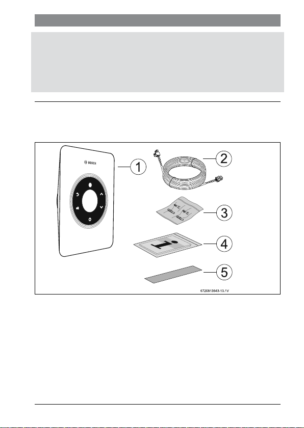
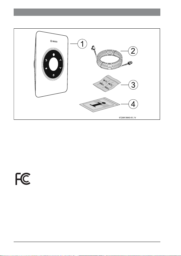
2.1 Scope of delivery, 7736504945 with Wi-Fi
Fig. 1 Scope of delivery
[1] Remote control
[2] Connection cable
[3] Screws
[4] Documentation
[5] Label
6 720 813 643 (2018/04)
8 | Remote control Kit
2.2 Scope of delivery, 7736504946 without Wi-Fi
Fig. 2 Scope of delivery
[1] Remote control
[2] Connection cable
[3] Screws
[4] Documentation
2.3 Certification
Wi-Fi certification by;
6 720 813 643 (2018/04)
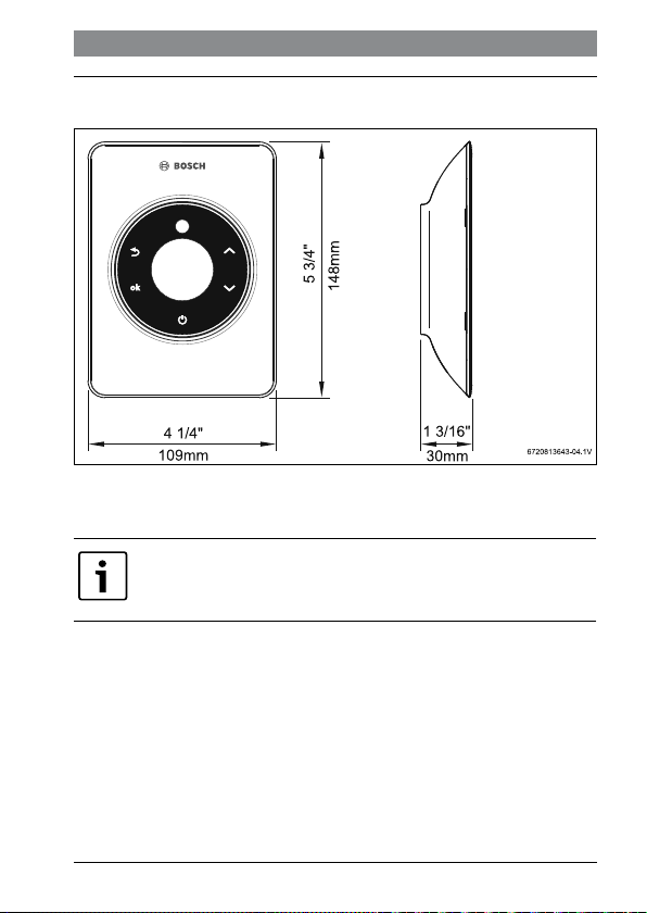
3 Technical data
Fig. 3 Dimensions
Remote control of Bosch water heaters.
Only connect to approved Bosch water heaters.
Technical data | 9
6 720 813 643 (2018/04)

10 | Installation
4 Installation
4.1 Proper location for installation
WARNING: Risk of scalding!
▶ Carefully select the location of the remote control to avoid
accidental water temperature settings.
Before installing the remote control,
▶ Check the Wi-Fi signal reception in the mounting vicinity.
If there is no Wi-Fi signal at the location of installation,
▶ Use a AP (Access Point) to increase Wi-Fi signal.
4.2 Mounting the remote control on the wall
CAUTION: Risk of damaging the remote control!
Humidity will damage the remote control.
▶ Do not install the remote control in bathrooms or other wet
rooms.
6 720 813 643 (2018/04)
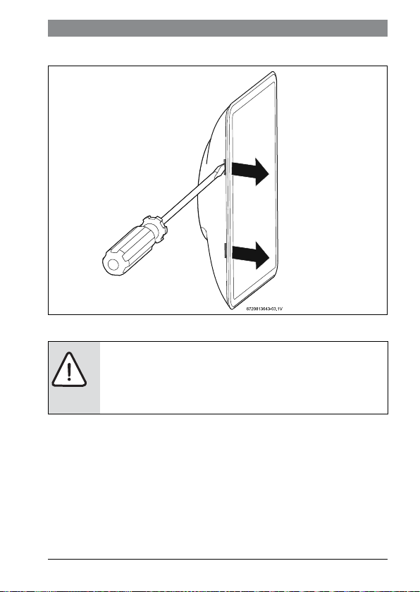
▶ Carefully open the remote control with a screw driver.
Fig. 4 Open remote control
CAUTION: Risk of damage the remote control internal
components!
Electrostatic discharge can damage internal components.
▶ Do not touch on the internal components.
Installation | 11
6 720 813 643 (2018/04)
12 | Installation
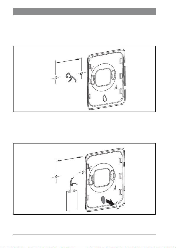
▶ Run the cable from the water heater to the mounting location.
▶ The cable can be either run inside the wall or outside the wall.
▶ Using the protruding cable as the center point, mark two level holes 2 3/8 inches
apart.
2 3/8 in
(60mm)
6720813643-06.2V
Fig. 5 Wires inside the wall
▶ Remove the cap from the base.
▶ Position the base level on the wall at the desired height.
▶ Mark two level holes within the screw guides in the base.
2 3/8 in
(60mm)
Fig. 6 Wires outside the wall
6720813643-07.1V
6 720 813 643 (2018/04)
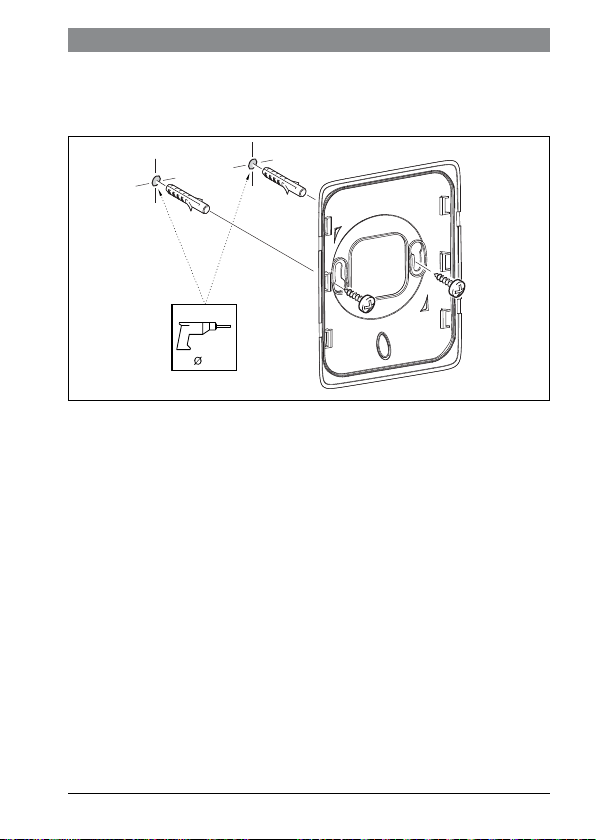
▶ Drill 1/4 inch holes in the marked locations.
▶ Insert the two supplied wall expansions.
▶ Mount the base using the two provided screws.
1/4 in
Fig. 7 Mounting the base
Installation | 13
6720813643-02.2V
6 720 813 643 (2018/04)
14 | Installation
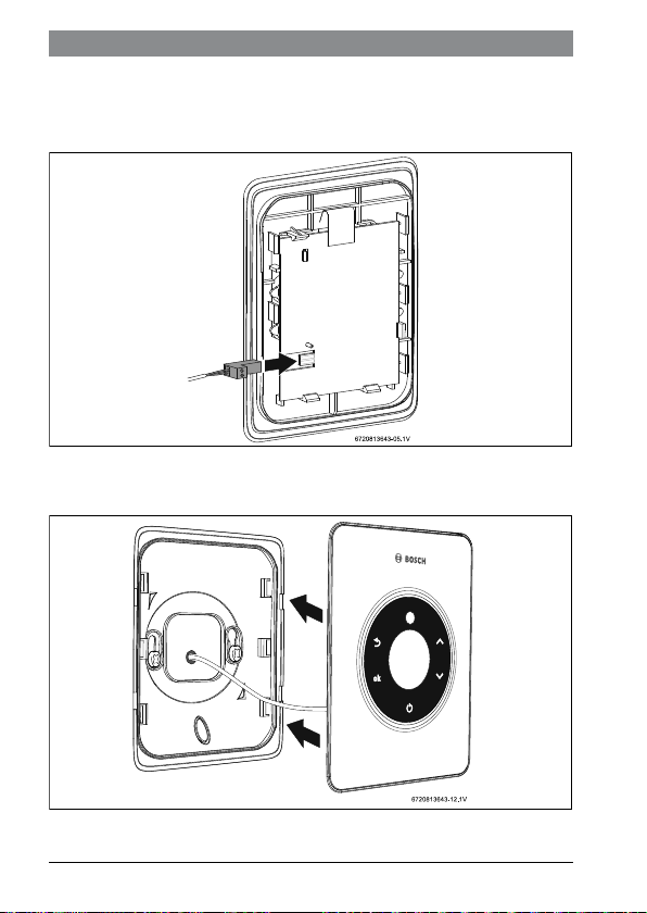
4.2.1 Power connection
Power is supplied to the remote control via supplied communication cable.
▶ Connect the communication cable to the remote control.
Fig. 8 Connection of the remote control
▶ Assemble the remote control interface to the mounted base.
Fig. 9 Assemble remote control
6 720 813 643 (2018/04)
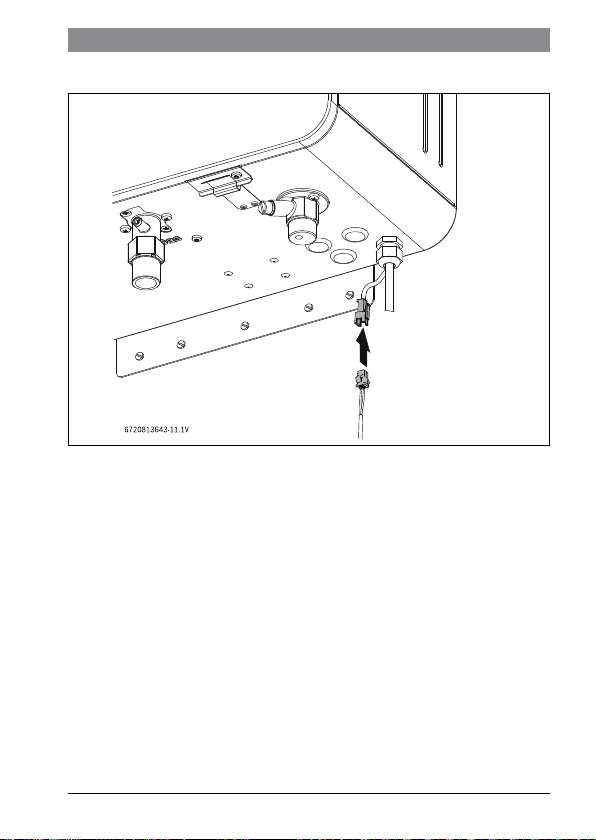
▶ Connect the communication cable to the water heater.
Fig. 10 Connection to the water heater
Installation | 15
6 720 813 643 (2018/04)
 Loading...