

Page 1

Room sealed gas continuous flow water heaters
6720808879-00.1V
Optiflow Professional
GWH12/16/20 1 CTD E23/31 F5 L
Installation Manual
Read installation manual prior to installation of this appliance!
Read user manual before putting this unit in operation!
Observe the warnings in the manuals!
The installation location must meet the requirements for sufficient ventilation!
Installation by an authorised person only!
6 720 810 560 (2016/06) AU
Page 2

2 | Index
Index
1 Key to symbols and safety instructions . . . . . . . . . . 3
1.1 Key to symbols . . . . . . . . . . . . . . . . . . . . . . . 3
1.2 Safety Information . . . . . . . . . . . . . . . . . . . . . 3
2 Product details . . . . . . . . . . . . . . . . . . . . . . . . . . . . . . . 5
2.1 Declaration of Conformity . . . . . . . . . . . . . . 5
2.2 Type overview . . . . . . . . . . . . . . . . . . . . . . . . 5
2.3 Included Items . . . . . . . . . . . . . . . . . . . . . . . . 5
2.4 Rating plate . . . . . . . . . . . . . . . . . . . . . . . . . . 5
2.5 Description of appliance . . . . . . . . . . . . . . . . 5
2.6 Accessory . . . . . . . . . . . . . . . . . . . . . . . . . . . 5
2.7 Dimensions and minimum clearances . . . . . 6
2.8 Appliance layout . . . . . . . . . . . . . . . . . . . . . . 7
2.9 Electrical wiring diagram . . . . . . . . . . . . . . . 8
2.10 Specification . . . . . . . . . . . . . . . . . . . . . . . . . 9
2.11 Flue accessories . . . . . . . . . . . . . . . . . . . . . 10
2.11.1 Selecting the Right Flue . . . . . . . . . . . . . . . 10
2.11.2 Vertical installation . . . . . . . . . . . . . . . . . . . 12
2.11.3 Horizontal installation . . . . . . . . . . . . . . . . . 12
3 Regulations . . . . . . . . . . . . . . . . . . . . . . . . . . . . . . . . . 12
4 Installation (only by an authorised technicians) . 12
4.1 Important information . . . . . . . . . . . . . . . . . 12
4.2 Choice of installation site . . . . . . . . . . . . . . 13
4.2.1 Regulations concerning the installation
site . . . . . . . . . . . . . . . . . . . . . . . . . . . . . . . . 13
4.2.2 Overall flue length of the installation . . . . . 13
4.3 Minimum clearances . . . . . . . . . . . . . . . . . . 13
4.4 Fitting hanging-plate . . . . . . . . . . . . . . . . . . 14
4.5 Installing the appliance . . . . . . . . . . . . . . . . 14
4.6 Water connection . . . . . . . . . . . . . . . . . . . . 14
4.7 Gas connection . . . . . . . . . . . . . . . . . . . . . . 14
4.8 Installation of flue accessories . . . . . . . . . . 15
4.9 Altitude of installation site . . . . . . . . . . . . . 15
4.10 Electrical connection (only by authorised
technicians) . . . . . . . . . . . . . . . . . . . . . . . . 16
4.10.1 Connecting the power cable . . . . . . . . . . . . 16
4.11 Commissioning of the appliance . . . . . . . . 16
4.12 Changing the setpoint limit temperature
(only for 55 °C preset appliances) . . . . . . . 16
4.13 Delivery temperature calibration . . . . . . . . 16
5 Regulating the gas (only for authorised
technicians) . . . . . . . . . . . . . . . . . . . . . . . . . . . . . . . . .17
5.1 Factory settings . . . . . . . . . . . . . . . . . . . . . . 17
5.2 Service function . . . . . . . . . . . . . . . . . . . . . 17
5.3 Adjusting the appliance . . . . . . . . . . . . . . . 17
5.3.1 Access to the test points . . . . . . . . . . . . . . . 17
5.3.2 Adjusting the maximum flow
(Parameter P1) . . . . . . . . . . . . . . . . . . . . . .17
5.3.3 Adjusting the minimum flow
(Parameter P2) . . . . . . . . . . . . . . . . . . . . . .18
5.3.4 Adjusting pressure at the burner
(Parameter P0) . . . . . . . . . . . . . . . . . . . . . .18
5.4 Factory default settings . . . . . . . . . . . . . . . 19
6 Maintenance (only by authorised service
technician) . . . . . . . . . . . . . . . . . . . . . . . . . . . . . . . . . .19
6.1 To remove the front panel . . . . . . . . . . . . . 19
6.2 Periodic maintenance . . . . . . . . . . . . . . . . . 20
6.3 Replacement of the fuse (electronic
control unit) . . . . . . . . . . . . . . . . . . . . . . . . .20
6.4 Start-up after completion of maintenance 20
6.5 Safe operation/ risk for prolonged use . . . 20
7 Troubleshooting . . . . . . . . . . . . . . . . . . . . . . . . . . . . . 21
8 Environmental considerations . . . . . . . . . . . . . . . . 23
9 Water quality . . . . . . . . . . . . . . . . . . . . . . . . . . . . . . . 23
10 Warranty details . . . . . . . . . . . . . . . . . . . . . . . . . . . . 24
6 720 810 560 (2016/06) Optiflow Professional
Page 3

Key to symbols and safety instructions | 3
1 Key to symbols and safety instructions
1.1 Key to symbols
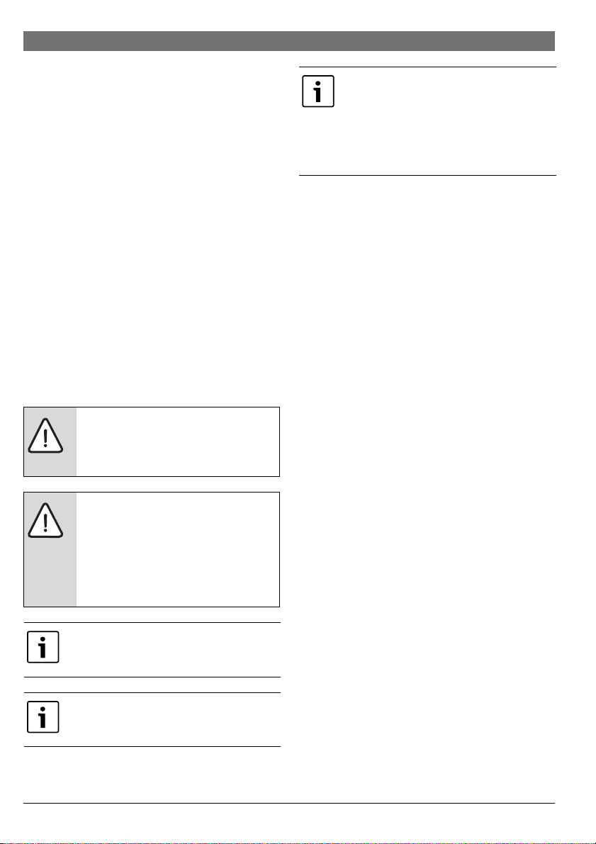
Warnings
Warnings in this document are identified by a
warning triangle printed against a grey
background.
Keywords at the start of a warning indicate
the type and seriousness of the ensuing risk
if measures to prevent the risk are not taken.
The following keywords are defined and used in this document:
• NOTICE indicates a situation that could result in damage to
property or equipment.
• CAUTION indicates a situation that could result in minor to
medium injury.
• WARNING indicates a situation that could result in severe
injury or death.
• DANGER indicates a situation that will result in severe
injury or death.
Important information
This symbol indicates important information
where there is no risk to people or property.
Additional symbols
Symbol Explanation
▶ Step in an action sequence
Cross-reference to another part of the document
•List entry
– List entry (second level)
Table 1
1.2 Safety Information
If you smell gas
A gas leak could potentia lly cause an explosion. If you smell gas,
observe the following rules.
▶ Avoid producing flames or sparks:
– Do not smoke, do not use a lighter or strike matches.
– Do not operate any electrical switches or unplug any
equipment.
– Do not use the telephone or ring doorbells.
▶ Turn off the gas supply at the main shut-off valve or at the
gas meter.
▶ Open windows and doors.
▶ Warn your neighbours and leave the building.
▶ Prevent anyone from entering the building.
▶ Stay well away from the building: call the emergency
services and the gas supplier.
If you notice dark combustion gases or sooting:
▶ Isolate the gas supply to the heater.
▶ Notify an authorised technician.
Installation, Assembly and Modifications
Installation, assembly and modifications to the heater must
only be performed by an authorised technician .
Maintenance
▶ The water heater is required to have a service and safety
inspection every two years.
▶ The installer is responsible for the safety and
environmental compatibility of the installation, according
to local regulations.
▶ The Owner/User is responsible for keeping the area around
the water heater free from debris.
▶ Safe access to inspect and service the water heater is the
responsibility of the property owner.
▶ Use only genuine Bosch spare parts.
Explosive and highly flammable material
▶ Do not store or use flammable material (paper, spray cans,
solvents, paints, etc) near the heater.
Combustion air and surrounding air
▶ The combustion air and surrounding air must be free from
corrosive substances.
▶ Do not spray aerosols or use chemicals around the heater
unless heater is disconnected from the power supply.
Risk of damage due to user error
User errors can result in injury and damage to property.
▶ Ensure that children never play with or operate this
appliance.
▶ Ensure that only personnel who can operate this appliance
correctly have access to it.
▶ Refer to the operating and user instructions before
adjusting the water heater.
To be installed and serviced only by an authorised person
The authorised installer is responsible for:
• Correct installation and commissioning of this appliance.
6 720 810 560 (2016/06)Optiflow Professional
Page 4
4 | Key to symbols and safety instructions
• Ensuring the appliance performs to the specifications
stated on the rating label.
• Demonstrating the operation of the appliance to the
customer before leaving.
• Handing the operating instructions to the customer.
THIS APPLIANCE IS NOT SUITABLE FOR POOL OR SPA POOL
APPLICATIONS.
NOT SUITABLE FOR COMMERCIAL BOOSTING OF A WARM
WATER RECIRCULATION SYSTEM
Regulations
All local by-laws and regulations pertaining to installation and
use of gas appliances must be observed.
This appliance must be installed in accordance with the
manufacturers installation instructions, AS/NZS5601, AS/
NZS3500, and all Local Building & Gas fitting regulations.
The appliance must not be installed outdoors. The appliance is
approved for indoor installation only. Do not install this
appliance with any modification or alteration.
Failure to install this appliance in accordance with these
installation instructions will void the warranty and may create
an unsafe situation.
Installation
DANGER: Explosion Risk!
▶ Always turn off the gas valve before
carrying out any work on components
which carry gas.
DANGER: Appliance malfunction!
This appliance must be installed with no
obstructions to the flue terminal.
▶ Periodic checking of the flue terminal to
ensure no blockage or obstruction of the
openings from plants, debris or insects
must be carried out.
The installation of gas, water, and electrical
supply, and the initial startup are to be
performed by an authorised person.
Not suitable for pool or spa pool applications.
Not suitable for commercial boosting of
warm water recirculation systems.
All gas appliances require adequate air intake
to ensure correct combustion. Insects and
dirt ingress may affect combustion causing
sooting. If you notice sooting from the flue
outlet the unit would require servicing. Pest
and dirt ingress is not covered by the
manufacturers warranty.
Important information
▶ Determine the most appropriate location for the appliance.
Install as close as possible to the most frequently used hot
water outlet.
▶ Ensure the mounting structure is capable of supporting the
weight of the appliance once installed. Secure the heater to
the wall using fixings suitable for the weight of the
appliance and the wall material.
▶ Install gas and water isolation valves as close as possible to
the appliance. Only use a gate valve or full flow ball valve
(fixed mechanism type) for cold water.
▶ Check the cold water supply pressure to ensure it meets
the required supply pressure for the appliance. (see
table 5, page 9).
▶ If inlet water pressure exceeds 800 kPa a pressure limiting
valve (500 kPa) MUST be fitted. The preferable location for
the pressure limiting valve is at the water meter.
▶ Where the pressure limiting valve is less than 3 metres from
the hot water unit, it must be fitted in conjunction with a
cold water expansion valve (700 kPa), between the water
heater and the pressure limiting valve.
▶ Failure to comply with this requirement may void the
warranty.
▶ Refer to AS/NZS5601 for the relevant gas pipe sizing.
▶ After finishing the gas piping system, the pipes must be
thoroughly purged and leak tested. This test must be
performed with the gas isolation valve of the appliance
closed.
▶ Ensure the gas pressure and flow through the regulator are
appropriate for the consumption of the heater (see table 5,
page 9). Refer to AS/NZS5601 and AS3500, for the
relevant pipe size.
Note: Incorrect pipe sizing or gas supply pressure may cause
the appliance to under perform. Service calls for incorrect pipe
sizing and/or gas pressure, will NOT be covered under
warranty.
6 720 810 560 (2016/06) Optiflow Professional
Page 5

Product details | 5
Safety of electrical appliances for domestic use and similar
purposes
The following requirements apply in accordance with EN
60335-1 in order to prevent hazards from occurring when
using electrical appliances:
“This appliance can be used by children of 8 years and older, as
well as by people with reduced physical, sensory or mental
capabilities or lacking in experience and knowledge, if they are
supervised and have been given instruction in the safe use of
the appliance and understand the resulting dangers. Children
must not play with the appliance. Cleaning and user
maintenance must not be performed by children without
supervision.”
“If the power cable is damaged, it must be replaced by the
manufacturer, its customer service department or a similarly
qualified person, so that risks are avoided.”
2 Product details
2.1 Declaration of Conformity
The appliance has been tested and certified to Australia
Standards.
Model GWH12/16/20 1 CTD E23/31 F5 L...
Table 2
2.2 Type overview
GWH 12 1CTDE23 F5 L
GWH 12 1CTDE31 F5 L
GWH 16 1CTDE23 F5 L
GWH 16 1CTDE31 F5 L
GWH 20 1CTDE23 F5 L
GWH 20 1CTDE31 F5 L
Table 3
[GWH] Gas continuous flow water heater
[12] Capacity (l/min)
[1] Generation
[CT] Thermostatic
[D] Digital user interface
[E] Electric ignition
[23] Appliance set for natural gas
[31] Appliance set for Universal LP gas
[F5] Tight chamber
[L] Locked water temperature adjustment
• Appliance documentation
2.4 Rating plate
The rating plate is located on the outside of the appliance, on
the bottom.
The rating plate has the indications on the performance of the
appliance, approval data and the serial number.
2.5 Description of appliance
• Room sealed wall-mounted appliance for internal
installation
• Multifunctional display panel
• Suitable for Natural Gas or Universal LPG
• Electronic ignition
•Water flow sensor
•Water valve
• Temperature sensors for monitoring the temperature of the
incoming and outgoing water of the appliance.
•Safety devices:
–Flame sensor rod
–Thermal fuse
– Hot water temperature sensor
– Electronic control unit
–Air temperature sensor
– Frost protection device
• Electrical connection: 230 V, 50 Hz
2.6 Accessory
• Flue accessories
• Mains remote control (optional).
• Bathroom remote control (optional).
2.3 Included Items
• Gas continuous flow water heater
• Fixing bracket
6 720 810 560 (2016/06)Optiflow Professional
Page 6

6 | Product details
2.7 Dimensions and minimum clearances
Fig. 1 Dimensions (in mm)
Connections
A B C D E Cold Hot Nat. Universal
GWH12 300 570 170 120 107
GWH20 364 570 175 142 137
Table 4 Dimensions (in mm)
6 720 810 560 (2016/06) Optiflow Professional
Water Gas
LPG
½“ ½“ ½“ ½“GWH16 364 570 175 142 137
Page 7
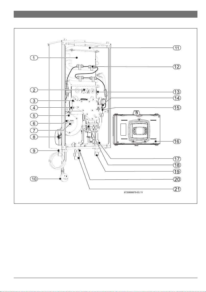
2.8 Appliance layout
Product details | 7
Fig. 2
[1] Heat exchanger
[2] Flame sensor rod
[3] Burner
[4] Air pressure test point
[5] Fan
[6] Air temperature sensor
[7] Thermal fuse
[8] Hot water temperature sensor
[9] Hot water outlet
[10] Power cord and plug
[11] Combustion gas collector
[12] Frost protection device
[13] Ignition electrode
[14] Burner pressure test point
[15] Water flow sensor and Water valve
[16] Electronic control unit
[17] Cold water temperature sensor
[18] Gas shut-off valve
[19] Cold water inlet
[20] Gas pressure test point
[21] Gas inlet
6 720 810 560 (2016/06)Optiflow Professional
Page 8
8 | Product details
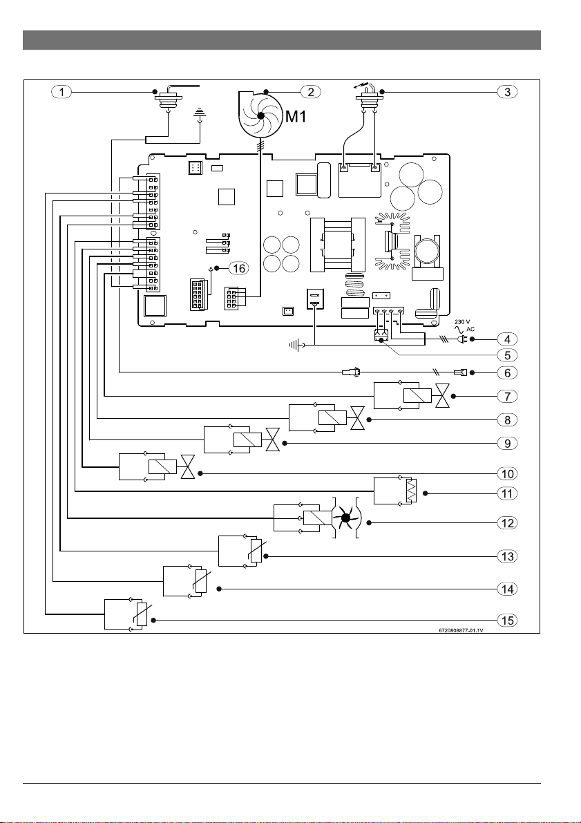
2.9 Electrical wiring diagram
Fig. 3 Electrical diagram
[1] Flame sensor rod
[2] Fan
[3] Ignition electrode
[4] Power supply
[5] Connection for frost protection
[6] Connection for remote control
[7] Modulation electrovalve (gas)
[8] Segmentation electrovalve 1 (gas)
6 720 810 560 (2016/06) Optiflow Professional
[9] Segmentation electrovalve 2 (gas)
[10] Safety electrovalve (gas)
[11] Thermal fuse
[12] Water flow sensor
[13] Air temperature sensor
[14] Hot water temperature sensor
[15] Cold water temperature sensor
[16] Water valve
Page 9

Product details | 9
2.10 Specification
Technical features Units GWH12 GWH16 GWH20
Performance
Nominal Gas Consumption MJ/h 90.0 120.2 149.0
Minimum gas consumption MJ/h 11.9 18.0 18.0
Efficiency at 100% of nominal load % 82.4 82.4 82.4
Gas supply data
Gas supply pressure (flowing)
Natural gas (when operating) kPa 1.13 1.13 1.13
Universal LP gas (when operating) kPa 2.75 2.75 2.75
Water supply data
Maximum permissible pressure (static) kPa 1000 1000 1000
Minimum operating pressure kPa 100 100 100
Start-up flow l/min 2.0 2.0 2.0
Maximum flow, corresponding to a temperature increase of 25 °C l/min 12.0 16.0 20.0
Maximum inlet temperature °C 50 50 50
Electrical circuit
Power supply voltage V
AC
Frequency Hz 50 50 50
Maximum power consumption W 228 228 228
230 230 230
Appliance enclosure rating IPX4D
General data
Weight (unpacked) kg 10 11 12
Height mm 570 570 570
Width mm 300 364 364
Depth mm 170 175 175
Table 5
6 720 810 560 (2016/06)Optiflow Professional
Page 10

10 | Product details
2.11 Flue accessories
Bosch 4000S coaxial flue must be used with
this appliance. Failure to use Bosch 4000S
flue could result in appliance failure.
DANGER: Install the flue gas pipe so that
there are no leaks.
▶ Non compliance with this requirement
may cause combustion gases to leak
through the appliance installation
compartment and may result in personal
injury or death.
Type Description Reference
AZ369 Vertical Flue Kit (Fixed 1.4m) 7 716 050 071
2.11.1 Selecting the Right Flue
▶ Map your flue configuration.
▶ Check that the configuration, including bends, is within the
maximum flue limits.
▶ Calculate whether a condensate trap is required using
Fig. 4.
▶ Choose the flue kit that best suits your application. The kit
includes the appliance adapter and terminal.
▶ Add any flue lengths, bends, or condensate traps required
for your configuration.
▶ Place your order using the Bosch part numbers shown
below.
Below is a list of accessories. Only use
original accessories.
AZ361 Telescopic Horizontal Flue Kit 500-725mm 7 716 050 063
AZ362 Horizontal Flue Kit (Fixed 0.8m) 7 716 050 064
--- Horizontal Flue Kit w/ Adaptor Ø 60/100 7 736 995 083
Table 6 Flue gas accessories Ø60/100 mm
6 720 810 560 (2016/06) Optiflow Professional
Page 11

Type Description Reference
(A)
10 m
9 m
7 m
6 m
8 m
5 m
4 m
3 m
2 m
1 m
0 m
0°C-5°C-10°C 5°C 10°C 15°C 20°C 25°C
(B)
6720809968-04.3V
--- Flue Elbow Ø 60/100 90° 7 736 995 079
--- Flue Elbow Ø 60/100 45° 7 736 995 071
--- Flue Terminal Extension DN60/100 350mm 7 736 995 059
--- Flue Terminal Extension DN60/100 750 mm 7 736 995 063
--- Flue Terminal Extension DN60/100 1500 mm 7 736 995 067
--- Horizontal Condensate Trap Ø 60/100 7 736 995 087
--- Vertical Flue Condensate Trap Ø 60/100 7 736 995 089
Table 6 Flue gas accessories Ø60/100 mm
Add note on using 100m 2 pce clips.
Product details | 11
Flue condensate collector
We advise using a condensate trap when the flue length and the
lowest average inlet air temperature is likely to result in
condensate forming during operation.
When the intersection of the flue length and lowest average
inlet air temperature is in the white section of the graph, a
condensate trap is required. (See Fig. 4)
Fig. 4
[A] Flue pipe length
[B] Lowest average inlet air temperature
Bosch 4000S flue components
All 4000S coaxial flue components have an internal pipe
diameter of 60 mm and an external pipe diameter of 100 mm.
6 720 810 560 (2016/06)Optiflow Professional
Page 12

12 | Regulations
2.11.2 Vertical installation
Maximum lengths (Lmax)
Lmax
Concentric pipes
GWH12
GWH16
GWH20 10 m
Table 7
2.11.3 Horizontal installation
Maximum lengths (Lmax)
GWH12 8 m
GWH16
GWH20 6 m
Table 8
In case of horizontal flue, ensure that the
installations has a fall of 3°.
Equivalent
lengths (Leq)
Ø
Ø 60/100 45° elbow
Ø 60/100 90° elbow 2 m 0.375 m
Table 9
Accessory Leq Min Length
12 m
Lmax
Concentric pipes
3Regulations
Any local by-laws and regulations pertaining to ins tallation and
use of gas-fired appliances must be observed.
This appliance must be installed in accordance with the
manufacturers installation instructions, AS/NZS5601 and all
Local Building & Gas fitting regulations
It is recommended that sanitary fixtures used for the purpose
of personal hygiene have a temperature limiting device such as
a tempering valve be fitted as per AS3498.
4 Installation (only by an authorised
technicians)
DANGER: Explosion!
▶ Always shut off the gas valve before
carrying out work on gas pipes.
The appliance installation, electrical
connection, gas connection, connection of
the flue system, and the initial start-up, are
operations to be carried out by authorised
technicians only.
NOTICE: Damage to the appliance!
▶ Do not place the device on the floor with
the connections facing downwards as
this may damage the appliance.
Installation in marine environments can lead
to premature corrosion. Premature
corrosion due to the installation environment
would not be covered by warranty.
Not suitable for pool or spa pool applications.
WARNING: Scalding!
This appliance can deliver water exceeding
50 °C.
▶ Please refer to AS/NZS 3500.4 local
requirements and installation
instructions to determine if additional
delivery temperature control is requ ired.
4.1 Important information
▶ Before carrying out the installation, consult the gas supply
company and the standard on gas appliances and
ventilation of rooms.
▶ Install in accordance with AS/NZS5601, AS/NZS3500.4,
NZS5261 and all local building, water and gas fitting
regulations.
6 720 810 560 (2016/06) Optiflow Professional
Page 13

4.2 Choice of installation site
6720817545-09.2V
N
C
J
B
J
A
C
A
K
G
A
H
N
F
J
A
C
K
B
B
B
G
K
H
Flue terminal positions
for water heaters in accordance
with AS/NZ5601
D
D
GM
P
K
E
E
4.2.1 Regulations concerning the installation site
▶ The water heater may not be installed over a heat source.
▶ Comply with the minimum installati on clearances indicated
in fig. 5 and table 10.
▶ Ensure there is a socket for electrical connection near the
water heater and it is easily accessible after the installation
of the water heater.
Location of the appliance
The combined air intake and flue terminal must terminate
outdoors in a well ventilated area away from vegetation and
other obstructions.
In order to prevent corrosion, the combustion air must not
contain any corrosive substances.
Substances classed as corrosion-promoting include
halogenated hydrocarbons containing chlorine and fluorine
compounds. They may be found in solvents, paints, adhesives,
aerosol propellants and household cleaners, for example.
If these conditions cannot be guaranteed, a different site must
be chosen for the appliance.
4.2.2 Overall flue length of the installation
The overall flue length may not exceed the values indicated in
the tables 7 and 8, and must not be less than the values
indicated in table 9 (Min length).
In determining the overall length of the installation, the
equivalent length (Leq) of each accessor y must be considered.
Installation (only by an authorised technicians) | 13
Fig. 5 Minimum distances
[A] Side 1 cm
[B] 40 cm
[C] Front 2 cm
Minimum distances to exhaustion points
In horizontal installations, the first elbow
positioned just at the outlet of the appliance
must not be considered for the purposes of
calculation.
Surface temperature
The maximum surface temperature of the appliance is below
85 °C. No special safety precautions are required with regard
to flammable building materials and cabinetry.
▶ Ensure that local building codes and regulations are
followed.
4.3 Minimum clearances
Consider the following limitations when determining the
installation location:
▶ Maximum length of the power cord.
▶ Allowances for service work while considering the
minimum distances indicated in fig. 6.
Fig. 6 Minimum flue clearances
6 720 810 560 (2016/06)Optiflow Professional
Page 14

14 | Installation (only by an authorised technicians)
Item Min.clea-
rance (mm)
A Below eaves, balconies and other
300
projections
B From the ground, above a balcony or other
surface
1)
C From a return wall or external corn er
300
1)
300
D From a gas meter (GM) 1000
E From an electricity meter or fuse box (P)
2)
500
F From a drain pipe or soil pipe 75
G Horizontally from any building structure 1)
500
or obstruction facing a terminal
H From any other flue terminal, cowl, or
combustion air intake
1)
300
J Horizontally from an openable window, door, non-
mechanical air inlet, or any other opening into a building
with the exception of sub-floor ventilation:
Appliances up to 150 MJ/h input
Appliances over 150 MJ/h input up to 200
MJ/h input
1)
K From a mechanical air inlet, including a spa
1)
300
300
1000
blower
N Vertically below an openable window, non-mechanical air
inlet, or any other opening into a building with the
exception of sub-floor ventilation:
Appliances over 50 MJ/h input and up to
1000
150 MJ/h input
Appliances over 150 MJ/h input 1500
Table 10
1) unless appliance is certified for closer installation
2) Prohibited area below electricity meter or fuse box extends
to ground level
4.4 Fitting hanging-plate
Before fitting the hanging-plate, ensure that
the water, gas, and flue connections can be
installed in this area.
No special wall protection is necessary. The wall has to be
capable of supporting the weight of the appliance.
▶ Find a suitable location.
▶ Drill the required holes.
▶ Fix the hanging plate using appropriate fixings (not
supplied).
4.5 Installing the appliance
NOTICE: The appliance may be damaged if
dirt is allowed to enter via the gas or water
connections.
▶ Purge the pipes to eliminate
possible foreign bodies.
▶ Remove the appliance from the packaging.
▶ Check that all the items indicated are included (section
2.3).
▶ Remove the covers from the gas and water connections.
▶ Check that the gas type available matches that shown on
the sticker on the front of appliance, and on its dataplate.
CAUTION:
▶ Never support or balance the water
heater on the water and gas
connections.
Packaging materials can be recycled.
4.6 Water connection
▶ Identify the cold and hot water pipe to avoid possible cross
connection.
▶ Install a pressure reducing valve if required. It's preferable
to install this valve close to the water meter.
▶ Complete the cold (fig. 2. [18]) and hot (fig. 2, [8]) water
connections.
4.7 Gas connection
DANGER:
Non-compliance with applicable legal
standards may cause, material damage,
personal injury, or even death.
The gas connection to the water heater must comply with the
AS/NZS5601.
▶ First ensure that the water heater corresponds to the gas
type available.
▶ Fit a gas isolation valve on the gas supply line as close as
possible to the appliance.
▶ After installation of the gas supply line, thorough purging
and a tightness test must be carried out.
6 720 810 560 (2016/06) Optiflow Professional
Page 15

Size gas supply as per AS/NZS5601.
Incorrect gas pipe sizing will not be covered
by the warranty.
4.8 Installation of flue accessories
The instructions in the respective manual mu st be followed for
the installation of the accessories.
DANGER: Install the flue gas pipe so that
there are no leaks!
▶ Non compliance with this requirement
may cause combustion gases to leak
through the appliance case and may
result in personal injury or death.
CAUTION:
Ensure that the flue is installed to the
requirements of AS/NZS5601.
▶ Once the connection of the flue is completed, ensure that
the seal is air tight.
Flue configuration
Bosch 4000S supplied flue must be used with these
appliances.
Cutting coaxial flue to length
When cutting flue to length please ensure that:
• All cuts are made on the male end of each flue component.
• The cuts are square (not on an angle) so that a complete
seal can be achieved on installation.
• The burrs are removed from the cut lengths of flue. If burrs
are not removed they may damage the internal seals in the
flue.
Maximum distance to the facade
In case of horizontal flue termination:
▶ Ensure that the distance between the end of the inlet air
pipe and the facade is no greater than 30 mm (Fig. 7).
Installation (only by an authorised technicians) | 15
Fig. 7 Dimensions
4.9 Altitude of installation site
To en sur e c or re ct o pe ra ti on o f t he ap pli an ce , a t al ti tu de s ab ov e
500m, the altitude setting must be adjusted.
▶ Enter the Service function (section 5.2).
Display will show “P2”.
▶ Press until the display shows “P4”.
▶ Press the button .
Display will show “E”.
▶ Press until the display shows “AS”.
▶ Press the button .
Display will show “1”.
▶ Press the button or and select the altitude of the
installation site according with table below.
Display Altitude
1 < 500 m
2 500 m - 1 000 m
3 1 000 m - 1 500 m
4 1 500 m - 2 000 m
5 2 000 m - 2 500 m
6 > 2500 m
Table 11
6 720 810 560 (2016/06)Optiflow Professional
Page 16

16 | Installation (only by an authorised technicians)
4.10 Electrical connection (only by authorised technicians)
DANGER: Due to electric shock!
▶ Before carrying out work on electrical
components, disconnect the power
supply (230 V AC) (by isolating switch
and removing the power plug from the
electrical socket) secure against
unintentional reconnection.
All the regulating, control and safety devices in the appliance
are factory supplied already connected and ready to operate.
4.10.1 Connecting the power cable
The electrical connection must be done in
accordance with AS/NZS3000.
If the power cable is damaged, it must be
replaced with a Bosch supplied spare part.
▶ Connect the power cable to a power socket.
4.11 Commissioning of the appliance
▶ Open the gas and water isolation valves and check the
tightness of all the connections.
When a hot water tap is turned on, the movement of water
through the flow sensor (fig. 2, [15]) sends a signal to the
control box. This signal triggers the following actions:
• The fan to start working.
• The ignition sequence and the gas valve (fig. 2, [18])
delivers gas to the burner.
• The burner ignites. Initially only a part of the burner is lit.
• The flame sensor rod (fig. 2, [2]) detects the flame.
• The temperature of the water is checked automatically by
the sensors. The appliance adjusts the gas flow and water
flow to achieve the temperature selected.
• Depending on the output required, the rest of the burner
will ignite.
Safety shut-down when the safety time is exceeded
If the appliance does not maintain a flame within the safety
interval stipulated, a safety shut-off is carried out.
Air in the gas supply line may cause a delay or difficulty when
igniting.
If the ignition attempt is unsuccessful after a period of time, the
safety devices block the op eration of the appliance, and air will
have to be purged from the circuit.
Safety shut-down due to an excessively high water temperature
The electronic control unit detects the temperature of the
water through the thermistor placed at the hot water outlet. If
the appliance detects an excessive temperature, a safety
shutoff will occur.
Safety shut-off due to incorrect flue conditions
If the appliance detects an incorrect flue condition, a safety
shut-off will occur.
Re-start after a safety shut-off
To put the appliance back into operation after a safety shut-off:
▶ Close all hot water taps.
▶ Reset the appliance by switching it off at the socket and
unplugging the cord.
4.12 Changing the setpoint limit temperature (only for 55 °C preset appliances)
The maximum temperature is preset to 55 °C. If required it can
be increased to 60 °C or 70 °C.
▶ Enter the Service function (section 5.2).
Display will show "P2".
▶ Press until the display shows "P4".
▶ Press the button .
Display will show "E".
▶ Press until the display shows "SL".
▶ Press the button .
Display will show "55"
▶ Press until the display shows "60" or “70”.
▶ Press the button for 3 seconds.
The value flashes to confirm the new setpoint limit.
4.13 Delivery temperature calibration
If the delivery temperature at the closest hot water outlet to the
appliance does not match the setpoint it can be adjusted as
follows:
▶ Enter the Service function (section 5.2).
Display will show "P2".
▶ Press until the display shows "P4".
▶ Press the button .
Display will show "E".
▶ Press until the display shows "SC".
▶ Press the button .
Display will show "0"
▶ Press or to adjust the delivery temperature as
required.
The setpoint can be adjusted between -5 °C and +5 °C.
6 720 810 560 (2016/06) Optiflow Professional
Page 17

Regulating the gas (only for authorised technicians) | 17
A
B
-
+
6720804089-11.1V
▶ Press the button for 3 seconds.
The value flashes to confirm the new setpoint limit.
Calibration example
Setpoint Water temp. at tap Calibration
50 °C 48 °C +2 °C
Table 12
5 Regulating the gas (only for authorised
technicians)
5.1 Factory settings
The data plate on the each appliance will show the factory
setting of that appliance.
Natural gas
The appliance must not be operated if the
dynamic connection pressure is less than
1.13 kPa or greater than 2.75 kPa.
Universal LPG
The appliance must not be operated if the
dynamic connection pressure is less than
2.5 kPa or greater than 4.5 kPa.
DANGER:
▶ The operations described below must only
be carried out by an authorised service
technician.
5.2 Service function
Accessing the service function
▶ Press and hold down at the same time , ,and
for 3 seconds.
Fig. 8 Service function
The display will show "P2".
The service function is now activated.
5.3 Adjusting the appliance
5.3.1 Access to the test points
▶ Remove the front of the appliance.
Fig. 9
[A] Air pressure test point
[B] Gas pressure test point
5.3.2 Adjusting the maximum flow (Parameter P1)
▶ Turn on the appliance using the ON/OFF button.
▶ Loosen the test point screw of the gas pressure test
point.[B]
▶ Connect the pressure gauge connection "+" to the gas
pressure test point [B].
6 720 810 560 (2016/06)Optiflow Professional
Page 18

18 | Regulating the gas (only for authorised technicians)
▶ Loosen the test point screw of the air pressure test
point.[A]
▶ Connect the negative "-" side of the pressure gauge to the
air pressure test point.[A]
▶ Press until the display shows "P1".
▶ Press the button .
Display will show "E".
▶ Press until the display shows "L1".
▶ Press the button .
The appliance is now ready for adjustment of the maximum
gas flow.
▶ Open a hot water tap.
▶ Press or until the pressure gauge shows the
value indicated in tab. 13.
If it is not possible to reach the differential
pressure value:
▶ Adjust the pressure in the burner
(section 5.3.4) and repeat the
procedure for adjusting maximum flow.
▶ Press for 3 seconds.
The displayed value flashes as a sign of confirmation.
▶Press .
Display will show "L1".
▶ Close the hot water tap.
▶ Press until the display shows "E".
▶ Press the button .
Display will show "P1".
The adjustment of the maximum gas flow is complete.
5.3.3 Adjusting the minimum flow (Parameter P2)
▶ Press until the display shows "P2".
▶ Press the button .
Display will show "E".
▶ Press until the display shows "L2".
▶ Press the button .
▶ Open a hot water tap.
The appliance is now ready for adjustment of the minimum
gas flow.
▶ Press or until the pressure gauge shows the
value indicated in tab. 13.
If it is not possible to reach the differential
pressure value:
▶ Adjust the pressure in the burner
(section 5.3.4) and repeat the
procedure for adjusting minimum flow.
▶ Press for 3 seconds.
The displayed value flashes as a sign of confirmation.
▶ Press .
Display will show "L2".
▶ Close the hot water tap.
▶ Press until the display shows "E".
▶ Press the button .
Display will show "P2".
▶ Simultaneously press the , and for 3
seconds.
Display will show the temperature selected.
▶ Disconnect the pressure gauge from the test points [A] and
[B].
▶ Tighten the shutter screws of the test points [A] and [B].
The adjustment of the minimum gas flow is complete.
Natural gas H Universal
LP gas
Øinjector
Dynamic
connection
pressure
(kPa)
Burner
pressure
(kPa) - P0
Differential
pressure of
the burner
MAX (kPa) P1
Differential
pressure of
the burner
MIN (kPa) P2
GWH12
GWH16
GWH20
GWH12
GWH16
GWH20
GWH12
GWH16
GWH20
GWH12
GWH16
GWH20
GWH12
GWH16
GWH20
1.7 1.3
2.0 + 1.7 1.5 + 1.3
1.13 2.75
0.12
0.46 - 0.50 0.63 - 0.67
0.37 - 0.41 0.63 - 0.67
0.33 - 0.37 0.44 - 0.49
0.05 - 0.08 0.05 - 0.08
0.05 - 0.07 0.05 - 0.07
0.04 - 0.08 0.05 - 0.08
Table 13 Pressure of the burner
5.3.4 Adjusting pressure at the burner (Parameter P0)
Burner pressure adjustment is only required
if “L1” and “L2” cannot be achieved
according to table 13.
6 720 810 560 (2016/06) Optiflow Professional
Page 19

▶ Enter the service mode by pressing and holding down the
, , and buttons simultaneously for 3
seconds (section 5.2).
Display will show "P2".
▶ Press until the display shows "P0".
▶ Press the button .
▶ Open a hot water tap.
With the pressure gauge connected, let the value measured
stabilise.
▶ Press or until the pressure gauge shows the
value indicated in tab. 13.
▶ Press for 3 seconds.
The displayed value flashes as a sign of confirmation.
▶ Press to exit this function.
Display will show "P0".
▶ Close the hot water tap.
The adjustment of the burner pressure is complete.
5.4 Factory default settings
▶ Enter the service mode by pressing and holding down the
, , and buttons simultaneously for 3
seconds (section 5.2).
Display will show "P2".
▶ Press until the display shows "P4".
▶ Press the button .
Display will show “E”.
▶ Press until the display shows "rP".
▶ Press the button .
Display will show "P1"
▶ Press for 3 seconds.
The displayed value flashes as a sign of confirmation.
▶Press .
Display will show "P1"
▶ Press until the display shows "P2".
▶ Press the button for 3 seconds.
The displayed value flashes as a sign of confirmation.
▶Press .
Factory default settings are now restored.
Maintenance (only by authorised service technician) | 19
6 Maintenanc e (only by authorised service
technician)
Bosch recommend that to maintain optimum performance
from this appliance, servicing should be carried out by suitably
licensed persons at intervals not greater than two (2) years.
Maintenance must only be performed by an
authorised service technician.
DANGER: Due to electric shock!
▶ Always isolate the electrical power to
the appliance (by turning off the power
point and removing the power plug from
the electrical socket) before carrying
out any work on electrical parts.
▶ Your appliance should only be attended to by a Bosch
service technician. To locate your nearest service provider,
call: AU 1300 30 70 37, NZ 080054 33 52.
▶ Only use Bosch supplied replacement parts.
6.1 To remove the front panel
▶ Remove the bezel around the display from the appliance by
gently levering it off with a screwdriver. (fig. 10, [1]).
▶ Loosen the 3 fixing screws from around the display and 2
front panel fixing screws from the underside of the
appliance (fig. 10, [2]).
Fig. 10 Remove the front
▶ Remove the front by lifting forwards and upwards.
6 720 810 560 (2016/06)Optiflow Professional
Page 20

20 | Maintenance (only by authorised service technician)
6.2 Periodic maintenance
Functional check
▶ Check the correct operation of all the safety, regulation and
verification elements.
Heat exchanger
▶ If the heat exchanger is showing signed of sooting:
– Remove the heat exchanger.
– Clean by applying a jet of water in the lengthw ise
direction of the fins.
NOTICE: Damage to the appliance.
Damage to the heat exchanger.
▶ Do not apply a jet that is too strong or
aimed in a direction other than that
indicated.
▶ If the soot is not removed use a stiff brush to carefully clean
the fins.
▶ Regions with average/high water hardness: descale the
inside of the heat exchanger and the connection pipes by
using a diluted solution of hydrochloric acid or white
vinegar.
▶ When reinstalling the heat exchanger replace the o-rings
and seals.
Burner
▶ Inspect the burner and clean it if necessary.
If cleaning is required:
▶ Dismantle the burner.
▶ Use a brush to clean the surface of the burner elements.
▶ Use a jet of air to blow the burner elements.
Water filter
▶ Close the cold water inlet isolation valve.
▶ Loosen the cold water pipe.
▶ Carefully remove the water filter.
▶ Replace with a new water filter.
6.3 Replacement of the fuse (electronic control unit)
▶ Loosen the fixing screw of the electronic control unit
▶ Release all the connections to the electronic control unit
▶ Open the electronic control unit
▶ Replace the fuse located in the corner of the circuit board.
6.4 Start-up after completion of maintenance
▶ Re-tighten all of the connections.
▶ Check the burner pressure.
▶ Check air tightness of the flue circuit with the front cover
fitted.
▶ Check that there are no gas or water leaks.
6.5 Safe operation/ risk for prolonged use
Prolonged use power wear some elements may cause gas leaks
and transhipment of products of combustion.
Preventively should:
▶ Make a visual inspection of the ma intenance intervals to the
following elements:
– Electrical contact of security sensor
–Fan
–Gas valve
–Combustion chamber
In case of corrosion visible:
▶ Call the intervention of a qualified contractor.
6 720 810 560 (2016/06) Optiflow Professional
Page 21

Troubleshooting | 21
7Troubleshooting
Fitting, maintenance and repair must only be carried out by authorised technicians. The following table describes the possible
solutions.
Display Description Possible solution
A0 Cold and hot water temperature sensor damaged. ▶ Check temperature sensor and associated
A1 Temperature inside the water heater housing is high
A4 Faulty air temperature sensor. ▶ Call an authorised service technician.
A7 Faulty hot water outlet temperature sensor. ▶ Check temperature sensor and associated
A9 Hot water outlet temperature sensor is not fitted
C7 Faulty fan. ▶ Check if the fan is properly connected to
CA Water flow above maximum specified value. ▶ Check incoming water pressure.
CF
C1
E0 Failure of control module ▶ Unplug the electrical connection for 10
E1 Hot water temperature sensor detects overheating. ▶ Let the appliance cool and try again.
E2 Faulty inlet water temperature sensor. ▶ Call an authorised service technician.
Table 14
(heat exchanger calcified or sooted).
properly.
Low incoming gas pressure.
Blocked flue gas outlet.
Air flow insufficient for start-up.
connections.
▶ If the problem persists, call an authorised
service technician.
▶ The appliance automatically regulates its
performance to avoid overheating.
▶ If the problem persists, call an authorised
service technician.
connections.
▶ If the problem persists, call an authorised
service technician.
▶ Check temperature sensor and associated
connections.
▶ If the problem persists, call an authorised
service technician.
ECU.
▶ If the problem persists, call an authorised
service technician.
▶ Install a pressure limiting valve if necessary.
▶ Remove dirt or any other impediment from
the flue terminal and/or pipe.
▶ Press the reset button.
If the problem persists, call an authorised
service technician.
seconds.
▶ Reconnect and restart the appliance.
▶ If the problem persists, call an authorised
service technician.
If the problem persists, call an authorised
service technician.
6 720 810 560 (2016/06)Optiflow Professional
Page 22

22 | Troubleshooting
Display Description Possible solution
E4 Air temperature sensor detects overheating (leaking
combustion products inside the combustion
chamber).
▶ Switch off at the power point and remove
the plug from the electrical socket.
▶ Do not try to Restart the appliance.
▶ Call a service agent immediately.
E9 Activated thermal fuse. ▶ Call an authorised service technician.
EA Flame not detected. ▶ Check that the gas to the appliance has not
been turned off.
▶ Unplug the electrical connection for 10
seconds.
▶ Reconnect and restart the appliance.
▶ If the problem persists, call an authorised
service technician.
EC Failure ionization during operation ▶ Check type of gas.
▶ Check gas pressure.
▶ Check the ignition system.
▶ Check the output of combustion gases and
remove dirt or other impediment to good
extraction.
EE Modulating solenoid valve disconnected. ▶ Check solenoid connections.
▶ If the problem persists, call an authorised
service technician.
EF Wrong gas connected. ▶ Call an authorised service technician.
F7 A flame is detected although the appliance is
switched off.
▶ Unplug the electrical connection for 10
seconds.
▶ Reconnect and restart the appliance.
▶ If the problem persists, call an authorised
service technician.
F9 Safety Solenoid valve disconnected. ▶ Call an authorised service technician.
FA Fault in the gas control valve. ▶ Call an authorised service technician.
FC Buttons stuck in a “pressed” position for more than
30 seconds.
▶ Release the button.
▶ If the problem persists, call an authorised
service technician.
With indication,
but without existence of
solar thermal system.
With indication
and water temperature
low.
The temperature selected is lower than the minimum
power that the appliance supplies.
High incoming water temperatures, or low flow rate
can create this occurrence.
▶ Increase the hot water flow.
-or-
▶ Select a higher temperature.
▶ If the problem persists:
▶ Call an authorised service technician.
Appliance is making a resonance noise (vibration). ▶ Call an authorised service technician.
Table 14
Note: breakdowns diagnosed by the water heater through an indication in the LCD panel result in the blocking of the appliance for
safety reasons. Once the problem is solved, you have to press the on/off button for > 3 seconds to restart the appliance.
To locate your nearest service agent, call: AU 1300 30 70 37, NZ 0800 54 33 52.
6 720 810 560 (2016/06) Optiflow Professional
Page 23

Environmental considerations | 23
8 Environmental considerations
Environmental protection is a fundamental corporate strategy
of the Bosch Group.
The quality of our products, their efficiency and environmental
safety are all of equal importance to us and all environmental
protection legislation and regulations are strictly observed.
We use the best possible technology and materials for
protecting the environment taking into account economic
considerations.
Packaging
We participate in the recycling programmes of the countries in
which our products are sold to ensure optimum recycling.
All of our packaging materials are environmentally friendly and
can be recycled.
Used appliances
Used appliances contain valuable materials that should be
recycled.
The various assemblies can be easily dismantled and synthetic
materials are marked accordingly. Assemblies can therefore be
sorted by composition and passed on for recycling or disposal.
9 Water quality
All Bosch water heating appliances are constructed from high
quality materials and components and all are certified for
compliance with relevant parts of Australian and New Zealand
gas, electrical and water standards.
Whilst Bosch water heaters are warranted against defects, the
warranty is conditional upon correct installation and use, in
accordance with detailed instructions provided with the
heater. In the case of the water supplied to the heater, it is
important that the water quality be of an acceptable standard.
The water quality limits/parameters listed in water quality table
are considered acceptable and generally, Australian and New
Zealand suburban water supplies fall within these limits/
parameters.
In areas of Australia and New Zealand where water may be
supplied, either fully or partly, from bores, artesian wells or
similar, one or more of the important limits may well be
exceeded and the heater could, therefore, be at risk of failure.
Where uncertainty exists concerning water quality, intending
appliance users should seek a water analysis from the water
supplying authority and in cases where it is established that the
water supply does not meet the quality requirements of the
water quality table, the Bosch warranty would not apply.
Water quality table
Maximum levels
Index(LSI)
(langelier)
pH
6.5-9.0 +0.4 to -1.0
Table 15
Saturation
at 65 °C
Total
200
mg/l
Hardness
Chlorides
250
mg/l
Iron
Sodium
180
mg/l1 mg/l
6 720 810 560 (2016/06)Optiflow Professional
Page 24

24 | Warranty details
10 Warranty details
Robert Bosch (Australia) Pty Ltd (Bosch) Manufacturer's Warranty (Applicable for purchases from 1 January 2012)
All Bosch hot water units are carefully checked, tested and
subject to stringent quality controls.
1. Warranty
Bosch offers, at its option, to repair or exchange this Bosch hot
water unit or the relevant part listed in clause 2 below at no
charge, if it becomes faulty or defective in manufacture or
materials during the warranty period also stated in clause 2.
This warranty is offered in addition to any other rights or
remedies held by a consumer at law.
2. Warranty periods & coverage (a) Domestic applications: 3 years (parts and labour)
(b) Heat exchangers used in domestic applications: 12 years
(parts only)
(c) Commercial applications: 12 months (parts and labour)
(d) Heat exchangers used in commercial applications: 12
months (part and labour)
All warranty periods commence on the date of purchase of the
hot water unit by the end-user. However, where the date of
purchase by the end-user is more than 24 months after the
date of manufacture, all warranty periods will automatically
commence 24 months after the date of manufacture.
3. Warranty exclusions
This warranty is VOID if any damage to or failure of the hot
water unit is caused wholly or partly by:
(a) faulty installation
(b) neglect, misuse, accidental or non-accidental damage,
failure to follow instructions
(c) use of the unit for purposes other than which it was
designed or approved
(d) unauthorised repairs or alterations to the unit without
Bosch's consent
(e) use of unauthorised parts and accessories without Bosch's
consent
(f) use of non-potable water or bore wate r in the hot water unit
(see product instructions for further details)
(g) continued use after a fault becomes known or apparent.
This warranty DOES NOT include:
(a) costs of consumables or accessories
(b) wear and tear, normal or scheduled maintenance
(c) to the extent permitted by law, any damage to property,
personal injury, direct or indirect loss, con sequential losses or
other expenses
(d) changes in the condition or operational qualities of the hot
water unit due to incorrect storage or mounting or due to
climatic, environmental or other influences.
NOTE: Any service call costs incurred by the owner or user of
the hot water unit for any matter not covered by the terms of
this warranty will not be reimbursed by Bosch, even if those
costs are incurred during the warranty period. If the hot water
unit is located outside the usual operating area of a Bosch
service agent, the agent's travel, freight or similar costs are not
covered by this warranty and must be paid by the ow ner or user
of the hot water unit.
4. Warranty conditions (a) Proof of purchase may be required. (b) The hot water unit must be installed by an authorised and
licensed installer.
(c) Proof may be required of the date of installation and correct
commissioning of the hot water unit has been carried out to
Bosch's satisfaction (such as a certificate of compliance).
(d) Repair or replacement of the hot water unit or any parts
under this warranty does not lengthen or renew the warranty
period.
(e) This warranty is not transferable and is only offered to the
original purchaser of the hot water unit.
(f) No employee or agent of Bosch is authorised to amend the
terms of this warranty.
(g) This warranty only applies to Bosch hot water units
purchased from an authorised reseller and installed in Australia
or New Zealand.
(g) To the extent that any condition or warranty implied by law
is excludable, such condition or warranty is excluded.
5. How to lodge a warranty claim and warranty procedure (a) Warranty claims must be made with the Bosch Customer
Contact Centre (Australia: ph 1300 307 037; New Zealand: ph
0800 543 352). Please be ready to provide the model and
serial numbers, date of installation, purchase details and a full
description of the problem. Warranty claims must be made
before the end of the warranty period.
(b) All warranty service calls must co nducted by an authorised
Bosch service agent.
(c) Invoices for attendance and repair of a hot water unit by
third parties not authorised by Bosch will not be accepted for
payment by Bosch.
6. Privacy Act 1988 (Cth)
A customer's personal information collected during warranty
claims may be used for the provision of customer support, for
the provision of information about products and services and
for other marketing activities undertaken by Bosch and its
Bosch Service Agents who are authorised to carry out warrant y
repairs on behalf of Bosch (Purpose). Bosch is committed to
protecting the privacy of its cus tomers' personal information. It
will act in compliance with the National Privacy Principles and
6 720 810 560 (2016/06) Optiflow Professional
Page 25

Privacy Act 1988 (Cth). Bosch will not forward customers'
personal information to third parties other than for the
Purpose. A customer can object at any time to the use of their
personal information for the Purpose. Bosch will ce ase to use a
customer's personal information accordingly if an objection is
made.
7. Bosch contact details
If you have any questions about this warranty or to lodge a
warranty claim, please contact:
Robert Bosch (Australia) Pty Ltd
1555 Centre Road, Clayton, Victoria 3168
Tel: Australia: 1300 307 037
Tel: New Zealand: 0800 543 352
IMPORTANT NOTE FOR AUSTRALIAN CONSUMERS
Our goods come with guarantees that cannot be excluded
under the Australian Consumer Law. You are entitled to a
replacement or refund for a major failure and for compensation
for any other reasonably foreseeable loss or damage. You are
also entitled to have the goods repaired or replaced if the goods
fail to be of acceptable quality and the failure does not amount
to a major failure.
Warranty details | 25
6 720 810 560 (2016/06)Optiflow Professional
Page 26

26 |
Notes
6 720 810 560 (2016/06) Optiflow Professional
Page 27

Notes
| 27
6 720 810 560 (2016/06)Optiflow Professional
Page 28

6720810560
 Loading...