

Bosch 7736501960 Installation Guide
Electric Heat Pump Water Heater
6720801244-00.1V
Compress 3000 DW FOO
HP 270-2E 0 FOOV/S...
Installation instructions
Please read the installation instructions before installing the appliance!
Please read the operating instructions before commissioning the appliance!
Please observe the safety instructions in the operating instructions!
The installation location must meet the requirements for sufficient ventilation!
Installation must only be carried out by an authorised contractor!
6 720 808 869 (2017/06) AU

2 | Index
Index
1 Key to symbols and safety instructions . . . . . . . . . . 3
1.1 Key to symbols . . . . . . . . . . . . . . . . . . . . . . . 3
1.2 Safety information . . . . . . . . . . . . . . . . . . . . . 3
2 Standard delivery . . . . . . . . . . . . . . . . . . . . . . . . . . . . 6
3 Appliance details . . . . . . . . . . . . . . . . . . . . . . . . . . . . . 7
3.1 Overview . . . . . . . . . . . . . . . . . . . . . . . . . . . . 7
3.2 Features and safety devices . . . . . . . . . . . . . 7
3.3 Specification tables . . . . . . . . . . . . . . . . . . . . 9
3.4 Storing and transportation . . . . . . . . . . . . . 10
3.4.1 Transport using a forklift . . . . . . . . . . . . . . . 10
3.5 Operational principle (brief overview of
modes) . . . . . . . . . . . . . . . . . . . . . . . . . . . . 12
3.6 Dimensions . . . . . . . . . . . . . . . . . . . . . . . . . 14
3.7 Clearances . . . . . . . . . . . . . . . . . . . . . . . . . . 15
4 Installation instructions . . . . . . . . . . . . . . . . . . . . . . 16
4.1 Tools required . . . . . . . . . . . . . . . . . . . . . . . 16
4.2 Location requirements . . . . . . . . . . . . . . . . 16
4.3 Secure the appliance . . . . . . . . . . . . . . . . . 17
4.4 Water piping . . . . . . . . . . . . . . . . . . . . . . . . 17
4.4.1 Inlet - Outlet connections . . . . . . . . . . . . . . 17
4.4.2 Condensate Drain Tubes (not supplied with the
appliance) . . . . . . . . . . . . . . . . . . . . . . . . . . 17
4.4.3 PTR Valve (supplied with the appliance) . . 18
4.4.4 Temperature mixing device (not supplied with
the appliance) . . . . . . . . . . . . . . . . . . . . . . . 19
4.4.5 Pressure limiting valve (not supplied with the
appliance) . . . . . . . . . . . . . . . . . . . . . . . . . . 19
4.4.6 Expansion control valve (not supplied with the
appliance) . . . . . . . . . . . . . . . . . . . . . . . . . . 19
4.5 Electric requirements . . . . . . . . . . . . . . . . . 19
4.6 Installation with connectivity to Bosch
photovoltaic systems . . . . . . . . . . . . . . . . . 20
4.7 Installation configurations . . . . . . . . . . . . . 21
4.7.1 Ecological ambient heat recovery . . . . . . . 21
4.8 Insulation blanket . . . . . . . . . . . . . . . . . . . . 21
4.9 Fill the water storage tank . . . . . . . . . . . . . . 22
4.9.1 Water characteristics . . . . . . . . . . . . . . . . . 23
4.10 Installation checklist . . . . . . . . . . . . . . . . . . 23
4.11 What to expect from a “normal startup” . . . 25
4.12 Off-peak compatibility . . . . . . . . . . . . . . . . 25
4.13 Demand response . . . . . . . . . . . . . . . . . . . . 25
5 Appliance status information . . . . . . . . . . . . . . . . . 26
5.1 Safety warnings . . . . . . . . . . . . . . . . . . . . . . 26
5.2 Working display . . . . . . . . . . . . . . . . . . . . . . 27
5.3 Operation programs . . . . . . . . . . . . . . . . . . 27
5.4 Setting the domestic hot water temperature .
27
5.5 Main menu . . . . . . . . . . . . . . . . . . . . . . . . . . 28
5.6 "Prog" submenu - Operating programs . . . 28
5.6.1 "Manual" operating mode . . . . . . . . . . . . . . 28
5.6.2 "P1", "P2" and "P3" operating modes . . . . 28
5.6.3 "Hol" mode . . . . . . . . . . . . . . . . . . . . . . . . . . 28
5.6.4 "OFF" operating mode . . . . . . . . . . . . . . . . 29
5.7 "Set" submenu - Settings . . . . . . . . . . . . . . 29
5.7.1 Date - Setting the temperature unit, date, time
and day of the week . . . . . . . . . . . . . . . . . . .29
5.7.2 Prog - Timetable operating programing . . . 30
5.7.3 „Leg“ function - automatic ther mal disinfection
. . . . . . . . . . . . . . . . . . . . . . . . . . . . . . . . . . . .33
5.7.4 „PLUS“ - enhanced comfort function . . . . . 34
5.7.5 „HEA“ - heating by electrical assistance . . 35
5.7.6 „Purg“ function - purge . . . . . . . . . . . . . . . . 35
5.7.7 “PHot” - photovoltaic . . . . . . . . . . . . . . . . . 35
5.7.8 „Fset“ function - factory resetting . . . . . . . 37
5.8 „Info“ - information . . . . . . . . . . . . . . . . . . . 38
5.9 „Sft“ - software version . . . . . . . . . . . . . . . . 38
5.10 One shot boost and auto boost at negative
temperatures . . . . . . . . . . . . . . . . . . . . . . . .39
5.11 Troubleshooting . . . . . . . . . . . . . . . . . . . . . 40
5.12 Factory configurations . . . . . . . . . . . . . . . . 40
5.13 Controls . . . . . . . . . . . . . . . . . . . . . . . . . . . . 41
6 Maintenance and repair . . . . . . . . . . . . . . . . . . . . . . 42
6.1 Periodic Inspection . . . . . . . . . . . . . . . . . . . 42
6.2 Temperature and pressure relief valve (PTR
Valve) . . . . . . . . . . . . . . . . . . . . . . . . . . . . . .42
6.3 Flushing tank . . . . . . . . . . . . . . . . . . . . . . . . 42
6.4 Draining the Water Heater . . . . . . . . . . . . . 42
6.5 Vacation and Extended Shutdown . . . . . . . 43
6.6 Clearing the Condensation Drain Tubes . . 43
6.7 Refrigerant circuit . . . . . . . . . . . . . . . . . . . . 43
6.8 Anode Rod servicing . . . . . . . . . . . . . . . . . . 43
6.9 Checking/replacing the magnesium anode 43
6.10 Service menu . . . . . . . . . . . . . . . . . . . . . . . . 44
7 Display . . . . . . . . . . . . . . . . . . . . . . . . . . . . . . . . . . . . . 47
7.1 Fault display . . . . . . . . . . . . . . . . . . . . . . . . 47
7.2 Displays . . . . . . . . . . . . . . . . . . . . . . . . . . . . 47
8 Electrical diagram . . . . . . . . . . . . . . . . . . . . . . . . . . . 49
6 720 808 869 (2017/06) Compress 3000 DW FOO

9 Environmental protection . . . . . . . . . . . . . . . . . . . . 50
10 Warranty details . . . . . . . . . . . . . . . . . . . . . . . . . . . . 51
Index | 3
6 720 808 869 (2017/06)Compress 3000 DW FOO
4 | Key to symbols and safety instructions
1 Key to symbols and safety instructions
1.1 Key to symbols
Warnings
Warnings in this document are identified by a
warning triangle printed against a grey
background.
Keywords at the start of a warning indicate
the type and seriousness of the ensuing risk
if measures to prevent the risk are not taken.
The following keywords are defined and can be used in this
document:
• NOTICE indicates a situation that could result in damage to
property or equipment.
• CAUTION indicates a situation that could result in minor to
medium injury.
• WARNING indicates a situation that could result in severe
injury or death.
• DANGER indicates a situation that will result in severe
injury or death.
Important information
This symbol indicates important information
where there is no risk to people or property.
Additional symbols
Symbol Explanation
▶ Step in an action sequence
Cross-reference to another part of the document
•List entry
– List entry (second level)
Table 1
1.2 Safety information
„Water“ safety warnings
WARNING:
This water heater is not suitable for pool
heating.
WARNING:
The appliance should be located in an area
where leakage of the heater or connections
will not result in damage to the area adjacent
to the appliance or to lower floors of the
structure. When such locations cannot be
avoided, it is recommended that a suitable
drain pan, adequately drained, be installed
under the appliance.
WARNING:
If a water heater is installed in a closed water
supply system, such as one having a
backflow preventer in the cold water supply
line, means shall be provided to control
thermal expansion. Contact the water
supplier or local plumber on how to control
this situation.
WARNING:
Precautions must be taken prior to manually
operating the relief valve to avoid contact
with hot water coming out of the relief valve
and to prevent water damage.
WARNING:
If a relief valve discharges periodically, this
may be due to thermal expansion in a closed
water supply system. Contact the water
supplier or local plumber on how to correct
this situation. Do not plug the relief valve.
WARNING:
The temperature pressure relief valve
should be checked for performance every
six months or replaced at intervals not
exceeding 3 years, or more frequently in
areas where there is a high incidence of
water deposits.
6 720 808 869 (2017/06) Compress 3000 DW FOO
Key to symbols and safety instructions | 5
Refrigerant
▶ Please observe the relevant
environmental regulations when
using and reusing refrigerant. Do not
allow refrigerant to be discharged
into the environment. Use the
refrigerant R134a. It is nonflammable and does not have a
destructive impact on the ozone
layer.
▶ Before working on parts of the
refrigerant circuit, remove the
refrigerant to ensure work safety.
Use HFC-134a and PAG-OIL for
maintenance purposes. It contains
fluorinated greenhouse gas and is rated
with a greenhouse potential of 1300 in
the Kyoto Protocol.
„Electric“ safety warnings
WARNING:
This water heater contains electronic
equipment and 500V insulation tests must
only be conducted between active and earth
and between neutral and earth. An active to
neutral test WILL damage the electronics.
CAUTION:
Label all wires prior to disconnection when
servicing controls. Wiring errors can result in
improper and dangerous operation.
Verify proper operation after servicing.
WARNING:
Do not turn power off to the appliance if cold
weather is expected as components may be
damaged by freezing. If power needs to be
turned off or power failure occurs and
freezing conditions are expected, water
should be drained from the appliance.
„General“ safety warnings
Do not store or use gasoline or other
flammable, combustible or corrosive
vapors and liquids in the vicinity of this
or any other appliance.
WARNING:
Do not operate this system before reading
the manual.
WARNING:
This appliance must be installed,
commissioned and serviced by an
authorised person in accordance with all
applicable local rules and regulations.
WARNING:
All electrical work and fixed wiring must be
carried out by a qualified person and in
accordance with the Wiring Rules AS/NZS
3000 and local authority requirements.
DANGER:
Shock hazard: line voltage is present. Before
servicing the water heater, please cut the
power supply. Failure to do so could result in
severe personal injury or death.
WARNING:
Keep appliance area clear and free from
combustible materials, gasoline and other
flammable vapors and liquids.
For your safety
WARNING:
The power supply to the appliance must not
be activated until the system is filled with
water.
6 720 808 869 (2017/06)Compress 3000 DW FOO
6 | Key to symbols and safety instructions
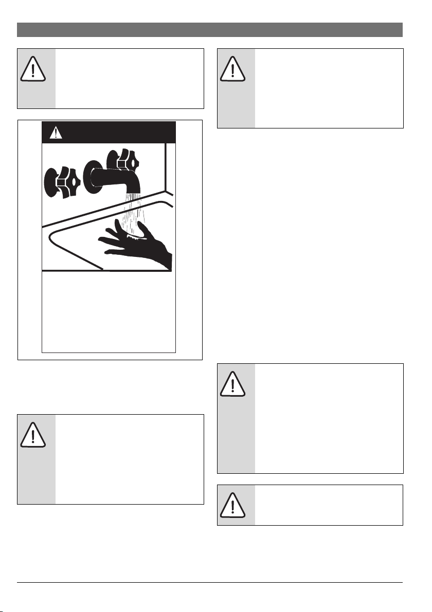
HOT
BURN
DANGER
Water temperature over 50°C can
cause severe burns instantly or
death from scalds.
Children, disabled and elderly are
at highest risk of being scalded.
Feel water before bathing or
showering.
6720801244-15.1V
WARNING:
To meet the requirements of the National
Plumbing Standard, the appliance runs a
weekly legionella disinfection cycle
automatically.
Fig. 1
To prevent serious injury, unit damage or damage to other
property, please use the unit properly. Read this manual
carefully and understand the following information correctly.
WARNING:
This appliance is not intended for use by
persons, including children, with reduced
physical, sensory or mental capabilities, or
lack of experience and knowledge, unless
they have been given supervision or
instruction concerning use of the appliance
by a person responsible for their safety.
WARNING:
Water temperatures over 50 °C can cause
severe scalds. Local regulations and/or the
requirements of AS/NZS 3500.4 must be
considered regarding the temperature
limitations of hot water used primarily for
personal hygiene.
High temperature water increases the risk of scald injury
This water heater can heat up water to temperatures which can
cause scalding. Always feel the water temperature before use,
either before having a shower or when filling a bath tub to
ensure it will not cause scald injuries.
We rec omm end , a nd i t ma y al so be r equ ire d b y re gul ati on s th at
an approved temperature limiting device is fitted into the hot
water pipe connected to sanitary outlets (i.e. bathroom and
ensuite). This will keep the water temperature below 50 °C at
these outlets. The risk of scald injury will be reduced and still
allow hotter water to the kitchen and laundry.
Notice to Victorian Customers from the Victorian Plumbing Industry Commission.
This water heater must be installed by a licensed person as
required by the Victorian Building Act 1993. Only a licensed
professional will give you a Compliance Certificate, showing
that the work complies with all the relevant standards. Only a
licensed person will have insurance protecting their
workmanship.
Make sure you use a licensed person to install thi s water heater
and ask for your Compliance Certificate.
WARNING:
Installation requirements are described in
chapter 4. The water heater must be
installed by an authorised person and the
installation must comply with Standards AS/
NZS 3500.4, AS/NZS 3000 and all local
codes and regulatory authority
requirements. In New Zealand, the
installation must conform with Clause G12 of
the New Zealand Building Code.
WARNING:
A wrong operation may lead to death or
serious injury to people.
6 720 808 869 (2017/06) Compress 3000 DW FOO
Every c are has been taken to ens ure accurac y in prepari ng this
document.
No liability can be accepted for any consequences, which may
1
2
6720801244-02.1V
3
arise as a result of its application.
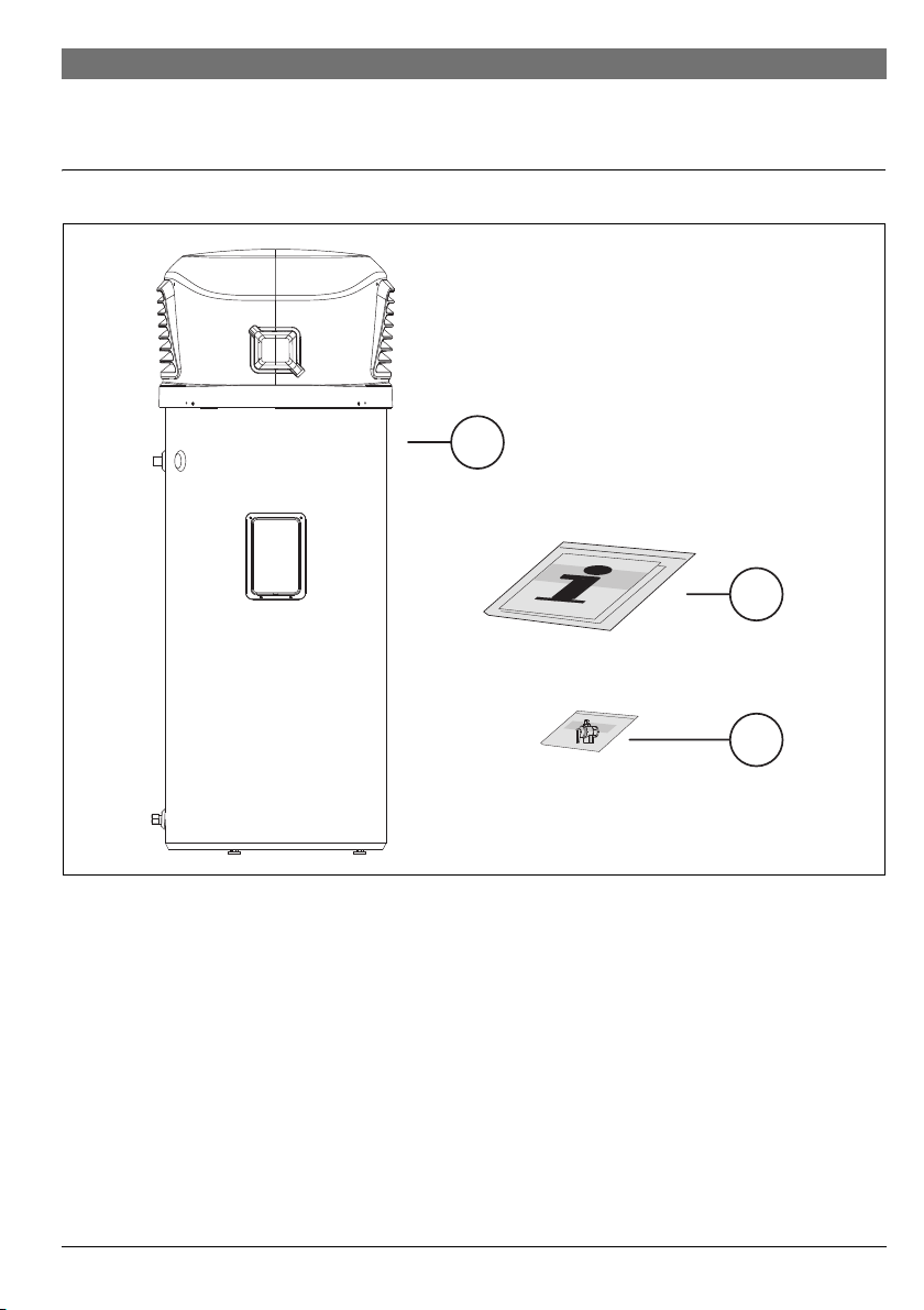
2 Standard delivery
Standard delivery | 7
Fig. 2
[1] Heat pump
[2] Set of printed documents for the appliance
[3] PTR valve (located)
6 720 808 869 (2017/06)Compress 3000 DW FOO
8 | Appliance details
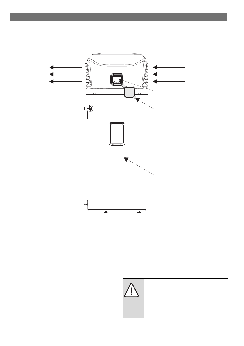
Air inletAir outlet
User
interface
User
interface
cap
Tank
6720801244-03.1V
3 Appliance details
3.1 Overview
Fig. 3 Appliance overview
3.2 Features and safety devices
Easy to operate and environmentally friendly
The heat pump has user interface with easy use menu keys for
programming. The heat pump is also environmentally friendly
as it transfers heat from the surrounding area into the water.
Heating capacity
The unit absorbs ambient energy and releases the heat into the
water stored in the tank. If the ambient temperature is low, the
heating capacity of the heat pump will be reduced, but you can
still rely on the electric element for backup: the electrical
element will automatically turn on below 0 °C to assist the heat
pump module.
6 720 808 869 (2017/06) Compress 3000 DW FOO
Thermal Cut Out (TCOs)
The water heater is equipped with one thermal cut-out (TCO)
located near the heating element. If for any reason the water
temperature becomes excessively high, the thermal cut-out
(TCO) cuts the power circuit to the heating element. Once
activated, the TCO must be reset manually. Resetting of the
temperature limiting control must be done by a qualified
service technician.
CAUTION:
The cause of the high temperature condition
must be investigated by a qualified service
technician and corrective actions must be
taken before placing the water heater in
service again.

Defrosting
During the heating, when the air temperature is between -7 °C
and 10 °C frost may be form ed at the evaporator, thus blocking
the air flow and reducing the heat transfer efficiency.
To avoid this occuring, the appliance will automatically defrost
the evaporator by injecting hot refrigerant gas into the
evaporator circuit via a bypass valve. The control of this
functionality relies on the temperature readings of the air and
fins sensors.
The defrost cycles last typically between 5 and 15 minutes and
their frequency depends on the environmental conditions (a ir
temperature and relative humidity).
During the defrost cycles only the compressor runs. After the
evaporator defrost is concluded the unit returns to normal
operation.
In case the air flow is restraint, for instance due to high wind
intensity at the air outlet, the frequency of defrost cycles might
increase.
Working condition
The appliance is designed to operate with best efficiency when
the air temperature is between -7 °C and +40 °C.
Care should be taken to feed the unit only with potable water
( section 4.9.1). Do not use untreated water from lakes,
rivers or groundwater!
Overheating protection
In case the water temperature near the electrical heating
element reaches 84 4 °C the power to the electrical element
is cut off by a thermostat mounted together with the electrical
heater and will require a manual reset.
Water temperature and pressure protection
The unit is supplied with a PTR valve for your safety (supplied
accessory). If the tank pressure reaches 1000kPa or the
temperature reaches 99 °C, the PTR valve will open
automatically to allow the pressure or temperature to decrease
to safe values.
The warranty can become void if relief valves or other safety
devices are tampered with or if the installation is not in
accordance with the instructions in this manual.
Mains Pressure
This water heater is designed for direct connection to mains
water supply. In case the mains supply pressure exceeds
800kPa, a pressure limiting valve must be installed
(section 4.4.4). A minimum water supply pressure of
200kPa is required to assure the effective operation of this
water heater.
Appliance details | 9
6 720 808 869 (2017/06)Compress 3000 DW FOO
10 | Appliance details
3.3 Specification tables
Model HP 270-2E 0 FOOV/S
Running ambient air temp. °C -7 °C/+40 °C
Outlet Water Temp. °C setpoint 1°C
Minimum Inlet Water Temp. °C 3 °C
Maximum Inlet Water Temp. °C 70 °C
Power supply Ph-V-Hz 1ph / 230V-240V / 50 Hz
IP rating IP X4
Storage size l 270
Water heating (HP cycle)
Water heating (Full mode)
2)
COP
Unit Dimension (D×H) mm 705 x 1840
Sound pressure level at 2 m dB (A) 43
Refrigerant type/Mass kg R134a / 0.375
Max. refrigerant circuit pressure kPa 2700
PTR valve setting
Throttling type Thermal expansion valve
System protection High pressure limiter, Temperature limiter
Compressor Model WHP01900
Fan motor Model W1G230EB
Water connections Water inlet ¾ BSP inch
Electric heating element Rated power input at 230 V kW 1.65
Table 2
1) Air at 15 °C and voltage supply 230V
2) According to EN255-3 by using air at 20 °C, water inlet at 15 °C and factory settings
3) PTR valve power capacity: 10 kW
1)
Heating capacity kW 1.5
Max. input kW 0.6
1)
Max. current A 2.6
Heating capacity kW 3.15
Max. input kW 2.25
Max. current A 9.8
3.3
Packing (W×H×D) mm 730 x 2004 x 730
Net/gross weight kg 113/128
3)
kPa 1000
Type Rotary
Brand Highly
Input W 700
Brand EBM Papst
Input W 28
Speed r/min 1500
Water outlet ¾ BSP inch
Max. water working pressure kPa 1000
PTR valve joint ½ BSP inch
Max inlet pressure kPa 800
Heat exchanger Double wall plate heat exchanger
Rated current at 230 V A 7.2
6 720 808 869 (2017/06) Compress 3000 DW FOO
Appliance details | 11
6720807918-08.1V
Operating ambient air temperature range:
Operating ambient temperature range of the heat pump cycle:
-7/ +40 °C.
The appliance can operate beyond the
normal temperature range by using the
electrical heater only.
Air Temp Humidity Water
Set Point Heating Up time Heat Up time w/
inlet
The hot water recover rate is dependent on the ambient air
temperature around the heat pump. The heat pump will
produce more hot water in a warmer ambient air temperature.
The table below shows heat up times at different air
temperatures.
COP N235 Water available at
PLUS
40ºC
[ºC] [%] [ºC] [ºC] [dm3]
-5 _ 10 56 11h45 0h20 11h45 0h20
1 90 10 56 17h30 0h20 9h00 1h00
9 87 10 56 11h00 0h20 7h00 1h00 3.0
15 70 15 56 8h00 0h20 8h00 0h20 3.3
335 20
20 60 15 56 7h15 0h15 7h15 0h15
32 60 15 56 5h15 0h15 5h15 0h15
Table 3
3.4 Storing and transportation
As a rule, the unit is to be stored and/or transported in its
original packaging, in upright position.
For transport over short distances (<500km), and provided
that original packaging is kept and due care is taken, horizontal
transportation is permitted. Nevertheless, an inclination angle
of up to 90° must be ensured, for compressor lifetime
assurance.
Both during transport and storage, ambient temperatures
between -20 °C and +60 °C are permissible.
In case the unit has been horizontally
transported to place, it must be positioned
upright at least one hour before it can be
turned on for the first time.
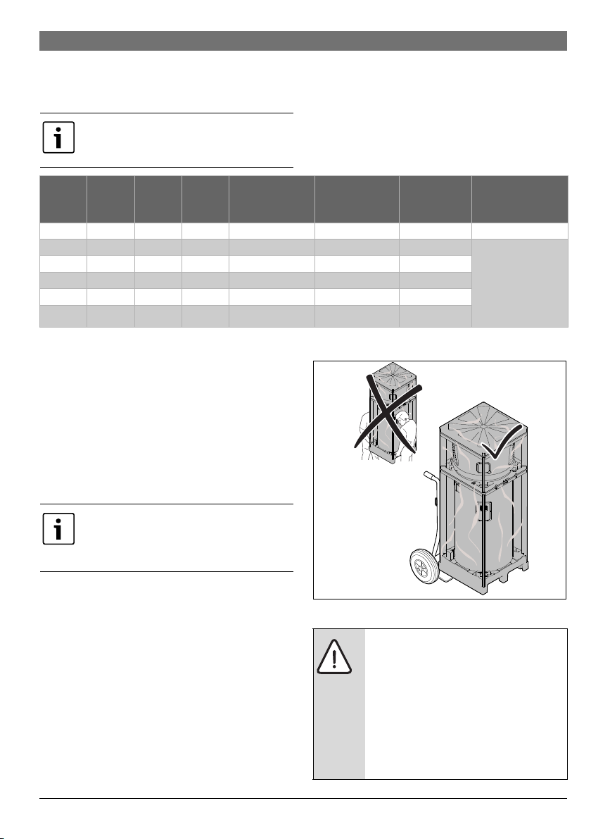
3.4.1 Transport using a forklift
When transported by a forklift, the unit must remain mounted
in the base. The lifting rate should be kept to a minimum. Due to
its top-heaviness, the unit must be secured to avoid tipping
over. To prevent any damage, the unit must be placed on a level
surface!
Fig. 4
WARNING:
Heat pumps are heavy and bulky. Australian
States and Territories have a Principal
Occupational Health and Safety (OH&S) Act
which contains requirements relating to the
handling of large, bulky or awkward items.
Persons installing this heat pump system
must be aware of their responsibilities and
be adequately trained and qualified in
accordance with local OH&S requirements.
6 720 808 869 (2017/06)Compress 3000 DW FOO

12 | Appliance details
WARNING: Transport damage!
▶ To avoid transport damage, wait until the
appliance is at the installation location to
remove the protective packaging.
▶ Use straps to prevent the appliance from
becoming scratched.
▶ Use suitable means of transport to bring
the appliance to the installati on location
(special car, pallet truck, etc).
6 720 808 869 (2017/06) Compress 3000 DW FOO
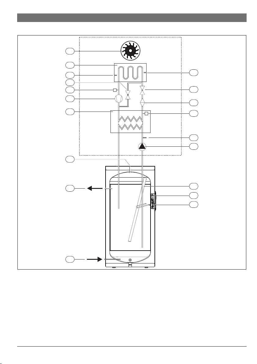
3.5 Operational principle (brief overview of modes)
1
2
3
4
6
7
16
10
11
14
13
6720807918-02.3V
5
12
15
9
17
18
8
19
Appliance details | 13
Fig. 5
[1] Air fan
[2] Evaporator
[3] Compressor
[4] Condenser (gas/water heat exchanger)
[5] NTC temperature sensor (air inlet)
[6] Hot water outlet
[7] Cold water inlet
[8] Electric heating element
[9] NTC temperature sensor (top of storage tank)
[10] DHW circulation pump
[11] NTC temperature sensor (bottom of storage tank)
[12] High-pressure pressure switch
[13] Expansion valve
[14] Filter dryer
[15] Low-pressure pressure switch
[16] Magnesium anode
[17] Temperature sensor at the evaporator fins
[18] Solenoid Valve
[19] Thermal Cut Out (TCO)
6 720 808 869 (2017/06)Compress 3000 DW FOO

14 | Appliance details
System basic theory
The refrigerant circuit is a closed system in which the
refrigerant R134a circulates as a heat transfer medium.
The evaporator transfers the heat from the air to the refrigerant
circuit, and the refrigerant evaporates into a gas.
The compressor compresses the refrigerant R134a, thus
increasing its temperature.
Then, the heat is transferred via a heat exchanger, also referred
to as a condenser, to the storage water tank. The refrigerant
R134a condenses in the process.
R134a flows through the expansion valve in a liquid state with
decreasing pressure, thus completing the cycle by being
routed back to the evaporator.
Brief overview of the appliance operation
Between 0 °C and 40 °C air temperature the appliance only
uses the economical heat pump cycle.
However, it is possible to manually turn on the electrical heater
together with the heat pump when the air is above 0 °C (One
shot boost). Once the set point is reached the boost is
automatically switched off.
Between -7 °C and 0 °C the appliance automatically switches
on the electrical heater together with heat pump cycle.
When the appliance has conditions to activate both electric and
compressor "FULL" is disp layed at the HMI, alternating with the
top tank temperature.
When compressor and electrical heater are operating together,
the upper part of the tank will rise much faster than the lower
part, thus boosting the recovering time for the next hot water
load. Hence, with "FULL" active, if the top temperature gets
near the set point and the bottom is still rather at low
temperature, the appliance, will automatically switch off the
electrical heater and continues the heating with the heat pump
cycle only but "FULL" will remain being displayed.
After the electrical heater is switched off, it is normal that the
top temperature start to decrease slowly. Therefore, while
rising the bottom temperature by only using the heat pump
cycle and until the top temperature start to increase to set
point, the electrical heater will be sw itc hed on a s m any tim es a s
required to keep the top near the set point.
Outside the air ambient range temperature, the unit operates
by only using the electrical heater.
6 720 808 869 (2017/06) Compress 3000 DW FOO
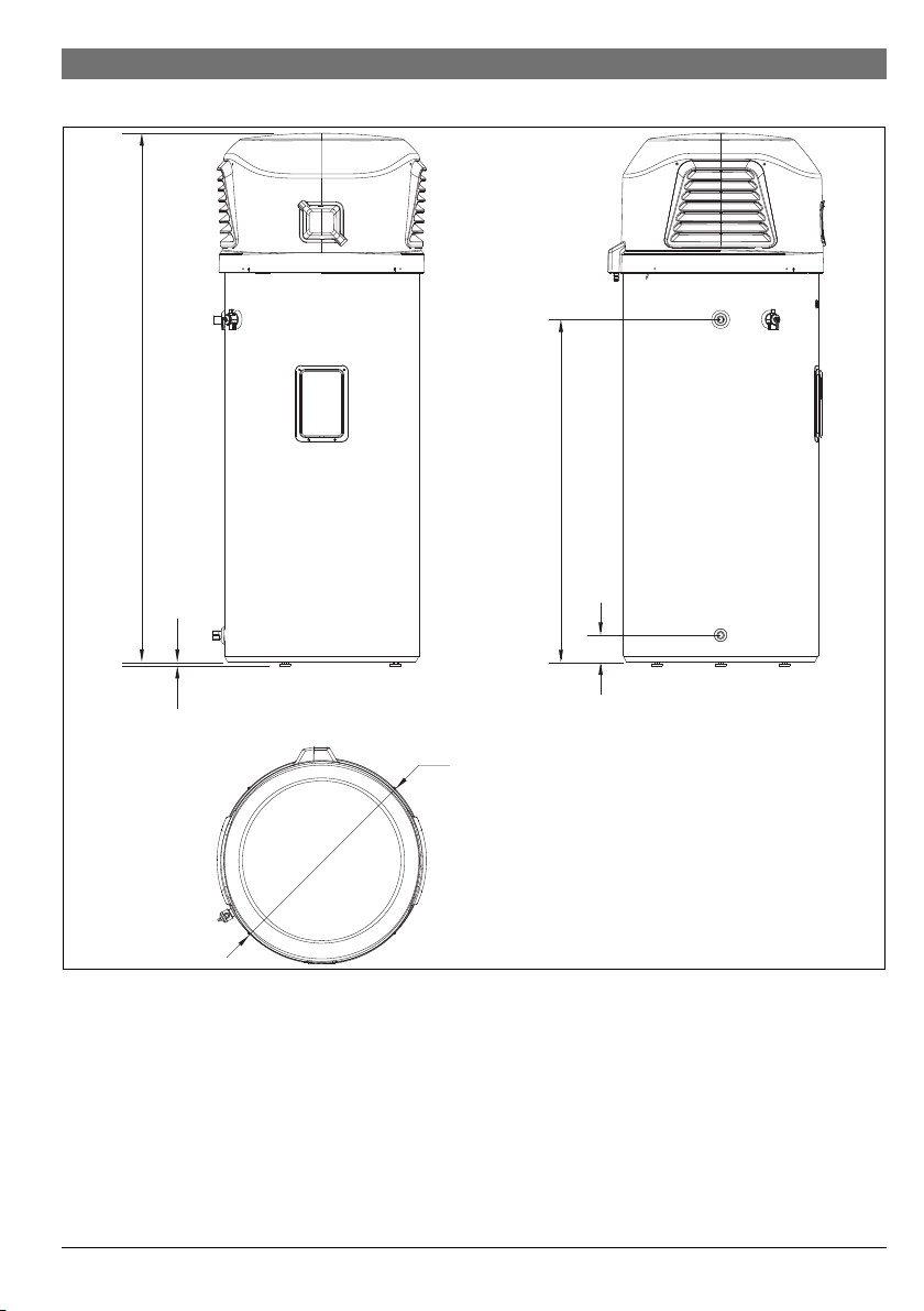
3.6 Dimensions
1840
16,5
1180
64
Ø 670
6720801244-06.1V
Appliance details | 15
Fig. 6 Dimensions (in mm)
6 720 808 869 (2017/06)Compress 3000 DW FOO
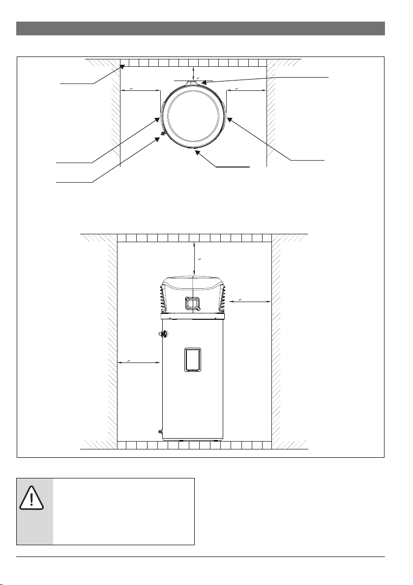
16 | Appliance details
>400mm >400mm
>400mm
>400mm
>600mm
Air outlet
Display
Barrier
Air inlet
6720807918-11.2V
Condensate drain
PTR valve
>50mm
3.7 Clearances
Fig. 7
DANGER:
The Temperature and Pressure relief valve
delivered with the unit must be installed and
must not be sealed or blocked. Failing to do
so will result in a dangerous situation
(section 4.4.3).
6 720 808 869 (2017/06) Compress 3000 DW FOO
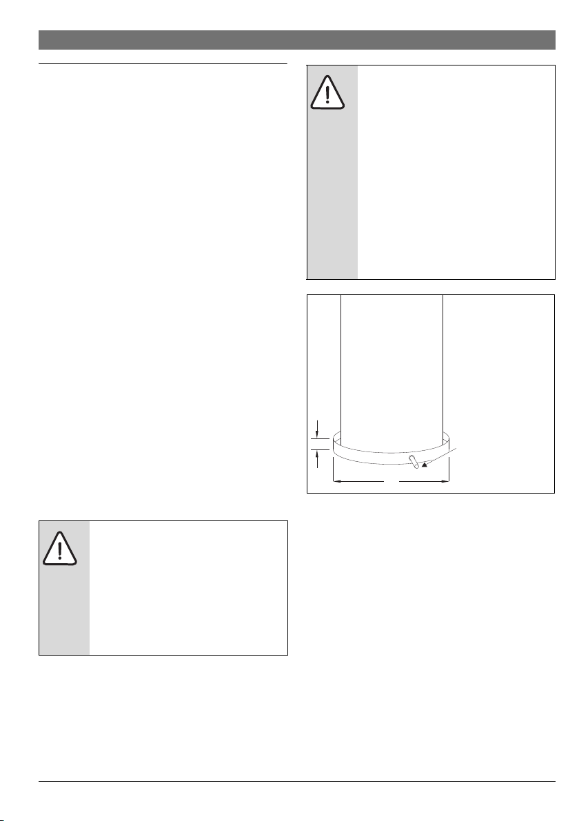
Installation instructions | 17
6720801244-11.1V
B
A
Route to open drain.
Line should be at least
DN50 and pitched for
proper drainage.
A= Ø of appliance
plus 50 mm min
B= Maximum 50 mm
4 Installation instructions
The manufacturer’s warranty does not cover any damage or
defect caused by improper installation, attachment or use of
any type of accessories (other than those listed in this user
manual) with this water heater. The use of unauthorized
energy-saving devices may shorten the life of the water heater
and may endanger life and cause property damage.
The manufacturer disclaims any responsibility for such loss or
injury resulting from the use of such unauthorized devices.
4.1 Tools required
• Wrenchs ¾ ", 10mm and 13mm.
• Philips screwdriver
4.2 Location requirements
Locate the water heater in a clean area as near as possible to
the area of biggest hot water demand. Long uninsulated hot
water lines can waste energy and water.
Note: Because this unit draws in ambient air to heat the water,
whe n us ing t he u nit i ndo ors, the roo m mus t be at le ast 3m x 3 m
x 2,5m (22,5 m
is smaller, there must be a louvered door with minimum
500cm
Place the water heater in such a way that clearance for proper
servicing is considered (section 3.7), namely for top cover
removal, PTR valve access and anode rod removal and
installation.
Remember you may need to remove the entire unit later for
servicing.
The water heater and water lines should be protected from
freezing temperatures and highly corrosive atmospheres.
3
) or larger, and preferably vented. If the room
2
venting area.
CAUTION:
The water heater should not be located in an
area where leakage of the tank or connection
will result in damage to the area adjacent to
it or to lower floors of the structure. In places
where installation in such areas cannot be
avoided, it is recommended that a suitable
catch pan, adequately drained, be installed
under the water heater (Fig. 8).
WARNING:
This water heater SHOULD NOT be installed
in an area with a corrosive atmosphere
where chemicals or flammable liquids are
stored or where aerosol propellants are
released. When using outdoors, because of
natural air movement in a room or other
enclosed space, these corrosive/flammable
vapours can be carried from where they are
being used or stored. Any electric arc drawn
within the water heater's electronic controls
can ignite these vapours causing an
explosion or fire, which may result in severe
burns or death to those in range, as well as
property damage.
Fig. 8 Water heater support as specified in AS3500.4
NOTE: Auxiliary catch pan MUST conform to local codes. Catch
Pan Kits are available from the store where the water heater
was purchased, a builder store or any water heater distributor.
Recommendation
Even if this unit runs at very low noise levels, it is advisable to
install it away from any living area windows.
▶ Check council laws for specific localized rules in relation to
location requirements for this appliance.
Outdoor installation
This unit was designed both for outdoor and indoor installation.
Proper clearances must be observed.
Local installation regulations
The installation must comply with the requirements of AS/NZS
3500.4 and AS/NZS 3000 standards and all additional local
codes and regulatory authority re quirements.
6 720 808 869 (2017/06)Compress 3000 DW FOO
 Loading...