

Page 1
AutoDome 7000 Series (IP and HD)
AUTODOME 7000
Page 2

en Operation Manual
Page 3

AutoDome 7000 Series (IP and HD) Table of Contents | en 3
Table of contents
1
1.1 About this Manual 6
1.2 Legal Information 6
1.3 Safety Precautions 6
1.4 Important Safety Instructions 6
1.5 Important Notices 8
1.6 Connection in Applications 11
1.7 Customer Support and Service 11
2
2.1 Parts List, Installation 13
2.2 Tools Required 14
2.3 Additional Products Required 16
3
4
4.1 Stabilization 19
5
6
7
7.1 Description 24
7.2 Route Wires and Attach Connectors 24
7.3 Route Power through Intermediate Power Supply Box 28
7.4 Attach Pendant Arm to Power Supply Box 31
7.5 Make Connections in the Power Supply Box 32
7.6 Installing the VGA-PEND-WPLATE 33
7.7 Attach Pendant to Arm and Tighten 37
8
8.1 Description 40
8.2 Route Wires and Attach Connectors 40
8.3 Attach Cover Door to Power Supply Box 46
8.4 Installing the VGA-ROOF-MOUNT 47
8.5 Installing the VG4-A-9543 Pipe Mount 49
8.6 Wire the Pipe Interface Board 50
8.7 Attach Pendant to Pipe and Tighten 54
8.8 Make Connections in the Power Supply Box 56
9
9.1 Description 57
9.2 Dimensions 57
9.3 Prepare Drywall Ceiling for Installation 57
9.4 Prepare Suspension Ceiling for Installation 57
9.5 Wire the Interface Box 59
9.6 Interface Box Connections 61
9.7 Installing the Ceiling (IP54 Housing) Gasket 63
9.8 Attach Housing to the Interface Box 64
9.9 Secure Housing to Ceiling 66
10
11
11.1 Connecting the AUTODOME camera to the PC 70
Bosch Security Systems Operation Manual 2013.07 | 1.2.2 | F.01U.283.679
Safety EN 6
Unpacking 13
System overview 17
Pre-installation Checklist 18
Installing the Optional SD Card 20
Mount Power Supply Box (Wall, Mast (Pole), and Corner Mounts) 22
Installing the Pendant Arm Wall, Corner, and Mast (Pole) Mounts 24
Installing the Roof Parapet and Pipe Mounts 40
Installing the In-Ceiling Mount 57
Preparing the Bubble 67
Connection 70
Page 4

4 en | Table of Contents AutoDome 7000 Series (IP and HD)
11.2 Power Cable and Wire Distances Guides 70
11.3 Ethernet Connections 71
11.4 Fiber Optic Ethernet Media Converter (Optional) 72
11.5 Alarms and Relay Connections 73
11.6 Audio Connections (Optional) 76
12
Configuration 78
12.1 System Requirements 78
12.2 Configuring the AUTODOME 7000 Series Camera 79
12.3 Configuring Audio (Optional) 83
13
Configuration via IP, Basic Mode 84
13.1 Basic Mode: Device Access 84
13.2 Basic Mode: Date/Time 85
13.3 Basic Mode: Network 85
13.4 Basic Mode: Encoder 86
13.5 Basic Mode: Audio 87
13.6 Basic Mode: Recording 87
13.7 Basic Mode: System Overview 87
14
Configuration via IP, Advanced Mode 88
14.1 Advanced Mode: General 88
14.2 Identification 88
14.3 Password 89
14.4 Date/Time 89
14.5 Display Stamping 90
14.6 Advanced Mode: Web Interface 91
14.7 Appearance 92
14.8 LIVEPAGE Functions 93
14.9 Logging 94
14.10 Advanced Mode: Camera 94
14.11 Installer Menu 94
14.12 Encoder Profile 96
14.13 Encoder Streams 99
14.14 Privacy Masks 101
14.15 Camera Settings 102
14.16 Lens Settings 104
14.17 PTZ Settings 105
14.18 Diagnostics 106
14.19 Prepositions and Tours 106
14.20 Sectors 107
14.21 Miscellaneous 107
14.22 Logs 107
14.23 Audio 108
14.24 Pixel Counter 108
14.25 Advanced Mode: Recording 108
14.26 Storage Management 109
14.27 Recording Profiles 111
14.28 Maximum Retention Time 113
14.29 Recording Scheduler 114
14.30 Recording Status 115
14.31 Advanced Mode: Alarm 116
2013.07 | 1.2.2 | F.01U.283.679 Operation Manual Bosch Security Systems
Page 5

AutoDome 7000 Series (IP and HD) Table of Contents | en 5
14.32 Alarm Connections 116
14.33 VCA 118
14.34 Virtual Masks 124
14.35 Audio Alarm 125
14.36 Alarm E-Mail 126
14.37 Alarm Task Editor 127
14.38 Alarm Rules 127
14.39 Advanced Mode: Interfaces 128
14.40 Alarm Inputs 128
14.41 Alarm Outputs 128
14.42 Advanced Mode: Network 128
14.43 Network Access 128
14.44 Advanced 133
14.45 Multicast 134
14.46 Image Posting 135
14.47 Accounts 136
14.48 IPv4 Filter 136
14.49 Encryption 136
14.50 Advanced Mode: Service 137
14.51 Maintenance 137
14.52 Licenses 138
14.53 System Overview 138
15
Operation 139
15.1 Using the AUTODOME Camera 139
15.2 Using Intelligent Tracking 147
15.3 Recommended Use of Your Camera 149
15.3.1 BVIP Firmware Updates 151
16
17
18
19
Troubleshooting 153
Maintenance 155
Technical data 157
User Command Table 158
Index 160
Bosch Security Systems Operation Manual 2013.07 | 1.2.2 | F.01U.283.679
Page 6
!
!
6 en | Safety EN AutoDome 7000 Series (IP and HD)
1
1.1
1.2
1.3
Safety EN
About this Manual
This manual has been compiled with great care and the information it contains has been
thoroughly verified. The text was complete and correct at the time of printing. Because of the
ongoing development of products, the content of the manual may change without notice.
Bosch Security Systems accepts no liability for damage resulting directly or indirectly from
faults, incompleteness, or discrepancies between the manual and the product described.
Legal Information
Copyright
This manual is the intellectual property of Bosch Security Systems, Inc. and is protected by
copyright. All rights reserved.
Trademarks
All hardware and software product names used in this document are likely to be registered
trademarks and must be treated accordingly.
Safety Precautions
Danger!
This symbol indicates an imminently hazardous situation such as “Dangerous Voltage” inside
the product. If not avoided, this will result in an electrical shock, serious bodily injury, or
death.
1.4
Warning!
Indicates a potentially hazardous situation. If not avoided, this could result in serious bodily
injury or death.
Caution!
Indicates a potentially hazardous situation. If not avoided, this may result in minor or
moderate injury. Alerts the user to important instructions accompanying the unit.
Caution!
Indicates a potentially hazardous situation. If not avoided, this may result in property damage
or risk of damage to the unit.
Notice!
This symbol indicates information or a company policy that relates directly or indirectly to the
safety of personnel or protection of property.
Important Safety Instructions
Read, follow, and retain for future reference all of the following safety instructions. Heed all
warnings on the unit and in the operating instructions before operating the unit.
1. Cleaning - Unplug the unit from the outlet before cleaning. Follow any instructions
provided with the unit. Generally, using a dry cloth for cleaning is sufficient, but a moist
fluff-free cloth or leather shammy may also be used. Do not use liquid cleaners or aerosol
cleaners.
2013.07 | 1.2.2 | F.01U.283.679 Operation Manual Bosch Security Systems
Page 7

AutoDome 7000 Series (IP and HD)
Safety EN | en 7
2. Heat Sources - Do not install the unit near any heat sources such as radiators, heaters,
stoves, or other equipment (including amplifiers) that produce heat.
3. Ventilation - Any openings in the unit enclosure are provided for ventilation to prevent
overheating and ensure reliable operation. Do not block or cover these openings. Do not
place the unit in an enclosure unless proper ventilation is provided, or the manufacturer's
instructions have been adhered to.
4. Object and liquid entry - Never push objects of any kind into this unit through openings
as they may touch dangerous voltage points or short-out parts that could result in a fire
or electrical shock. Never spill liquid of any kind on the unit. Do not place objects filled
with liquids, such as vases or cups, on the unit.
5. Lightning - For added protection during a lightning storm, or when leaving this unit
unattended and unused for long periods, unplug the unit from the wall outlet and
disconnect the cable system. This will prevent damage to the unit from lightning and
power line surges.
6. Controls adjustment - Adjust only those controls specified in the operating instructions.
Improper adjustment of other controls may cause damage to the unit. Use of controls or
adjustments, or performance of procedures other than those specified, may result in
hazardous radiation exposure.
7. Overloading - Do not overload outlets and extension cords. This can cause fire or
electrical shock.
8. Power cord and plug protection - Protect the plug and power cord from foot traffic,
being pinched by items placed upon or against them at electrical outlets, and its exit from
the unit. For units intended to operate with 230 VAC, 50 Hz, the input and output power
cord must comply with the latest versions of IEC Publication 227 or IEC Publication 245.
9. Power disconnect - Units have power supplied to the unit whenever the power cord is
inserted into the power source, or when High Power-over-Ethernet (High PoE) power is
provided over the Ethernet CAT 5E/6 cable. The unit is operational only when the ON/OFF
switch is in the ON position. The power cord is the main power disconnect device for
switching off the voltage for all units. When High PoE or PoE+ (820.3at) is used to power
the unit, the power is provided over the Ethernet cable, which is then the main power
disconnect device for switching off the voltage for all units.
10. Power sources - Operate the unit only from the type of power source indicated on the
label. Before proceeding, be sure to disconnect the power from the cable to be installed
into the unit.
For battery powered units, refer to the operating instructions.
For external power supplied units, use only the recommended or approved power
supplies.
For limited power source units, this power source must comply with EN60950.
Substitutions may damage the unit or cause fire or shock.
For 24 VAC units, voltage applied to the unit's power input should not exceed ±10%, or
28 VAC. User-supplied wiring must comply with local electrical codes (Class 2 power
levels). Do not ground the supply at the terminals or at the unit's power supply terminals.
If unsure of the type of power supply to use, contact your dealer or local power company.
11. Servicing - Do not attempt to service this unit yourself. Opening or removing covers may
expose you to dangerous voltage or other hazards. Refer all servicing to qualified service
personnel.
12. Damage requiring service - Unplug the unit from the main AC power source and refer
servicing to qualified service personnel when any damage to the equipment has occurred,
such as:
the power supply cord or plug is damaged;
Bosch Security Systems Operation Manual 2013.07 | 1.2.2 | F.01U.283.679
Page 8
8 en | Safety EN AutoDome 7000 Series (IP and HD)
exposure to moisture, water, and/or inclement weather (rain, snow, etc.);
liquid has been spilled in or on the equipment;
an object has fallen into the unit;
unit has been dropped or the unit cabinet is damaged;
unit exhibits a distinct change in performance;
unit does not operate normally when the user correctly follows the operating instructions.
13. Replacement parts - Be sure the service technician uses replacement parts specified by
the manufacturer, or that have the same characteristics as the original parts.
Unauthorized substitutions may cause fire, electrical shock, or other hazards.
14. Safety check - Safety checks should be performed upon completion of service or repairs
to the unit to ensure proper operating condition.
15. Installation - Install in accordance with the manufacturer's instructions and in accordance
with applicable local codes.
16. Attachments, changes or modifications - Only use attachments/accessories specified by
the manufacturer. Any change or modification of the equipment, not expressly approved
by Bosch, could void the warranty or, in the case of an authorization agreement, authority
to operate the equipment.
1.5
Important Notices
Accessories - Do not place this unit on an unstable stand, tripod, bracket, or mount. The unit
may fall, causing serious injury and/or serious damage to the unit. Use only with the cart,
stand, tripod, bracket, or table specified by the manufacturer. When a cart is used, use
caution and care when moving the cart/apparatus combination to avoid injury from tip-over.
Quick stops, excessive force, or uneven surfaces may cause the cart/unit combination to
overturn. Mount the unit per the manufacturer's instructions.
All-pole power switch - Incorporate an all-pole power switch, with a contact separation of at
least 3 mm in each pole, into the electrical installation of the building.If it is needed to open
the housing for servicing and/or other activities, use this all-pole switch as the main
disconnect device for switching off the voltage to the unit.
Camera grounding - For mounting the camera in potentially damp environments, ensure to
ground the system using the ground connection of the power supply connector (see section:
Connecting external power supply).
Camera lens - An assembled camera lens in the outdoor housing must comply and be tested in
accordance with UL/IEC60950. Any output or signal lines from the camera must be SELV or
Limited Power Source. For safety reasons the environmental specification of the camera lens
assembly must be within the environmental specification of -10 °C (14 °F) to 50 °C (122 °F).
Camera signal - Protect the cable with a primary protector if the camera signal is beyond 140
feet, in accordance with NEC800 (CEC Section 60).
Coax grounding:
– Ground the cable system if connecting an outside cable system to the unit.
2013.07 | 1.2.2 | F.01U.283.679 Operation Manual Bosch Security Systems
Page 9
AutoDome 7000 Series (IP and HD) Safety EN | en 9
– Connect outdoor equipment to the unit's inputs only after this unit has had its grounding
plug connected to a grounded outlet or its ground terminal is properly connected to a
ground source.
– Disconnect the unit's input connectors from outdoor equipment before disconnecting the
grounding plug or grounding terminal.
– Follow proper safety precautions such as grounding for any outdoor device connected to
this unit.
U.S.A. models only - Section 810 of the National Electrical Code, ANSI/NFPA No.70, provides
information regarding proper grounding of the mount and supporting structure, grounding of
the coax to a discharge unit, size of grounding conductors, location of discharge unit,
connection to grounding electrodes, and requirements for the grounding electrode.
Notice!
This device is intended for use in public areas only.
U.S. federal law strictly prohibits surreptitious recording of oral communications.
Your Bosch product was developed and manufactured with high-quality material
and components that can be recycled and reused. This symbol means that electronic and
electrical appliances, which have reached the end of their working life, must be collected and
disposed of separately from household waste material. Separate collecting systems are usually
in place for disused electronic and electrical products. Please dispose of these units at an
environmentally compatible recycling facility, per European Directive 2002/96/EC.
Environmental statement - Bosch has a strong commitment towards the environment. This
unit has been designed to respect the environment as much as possible.
Electrostatic-sensitive device - Use proper CMOS/MOS-FET handling precautions to avoid
electrostatic discharge. NOTE: Wear required grounded wrist straps and observe proper ESD
safety precautions when handling the electrostatic-sensitive printed circuit boards, and when
inserting into or removing the SD card from the SD card slot.
Fuse rating - For security protection of the device, the branch circuit protection must be
secured with a maximum fuse rating of 16A. This must be in accordance with NEC800 (CEC
Section 60).
Grounding and polarization - This unit may be equipped with a polarized alternating current
line plug (a plug with one blade wider than the other blade). This safety feature allows the
plug to fit into the power outlet in only one way. If unable to insert the plug fully into the
outlet, contact a locally certified electrician to replace the obsolete outlet. Do not defeat the
safety purpose of the polarized plug.
Alternately, this unit may be equipped with a 3-pole grounding plug (a plug with a third pin for
earth grounding). This safety feature allows the plug to fit into a grounded power outlet only.
If unable to insert the plug into the outlet, contact a locally certified electrician to replace the
obsolete outlet. Do not defeat the safety purpose of the grounding plug.
Moving - Disconnect the power before moving the unit. Move the unit with care. Excessive
force or shock may damage the unit and the hard disk drives.
Outdoor signals - The installation for outdoor signals, especially regarding clearance from
power and lightning conductors and transient protection, must be in accordance with NEC725
and NEC800 (CEC Rule 16-224 and CEC Section 60).
Bosch Security Systems Operation Manual 2013.07 | 1.2.2 | F.01U.283.679
Page 10
10 en | Safety EN AutoDome 7000 Series (IP and HD)
Permanently connected equipment - Incorporate a readily accessible disconnect device in the
building installation wiring.
Pluggable equipment - Install the socket outlet near the equipment so it is easily accessible.
High PoE or PoE+ (802.3at) – Never supply power via the Ethernet connection (High PoE or
PoE+) when power is already supplied via the power connector, unless implementing an
Auxiliary Power application (described in the section Connection in Applications, page 11).
Power lines - Do not locate the camera near overhead power lines, power circuits, or
electrical lights, nor where it may contact such power lines, circuits, or lights.
SELV - All the input/output ports are Safety Extra Low Voltage (SELV) circuits. SELV circuits
should only be connected to other SELV circuits.
Because the ISDN circuits are treated like telephone-network voltage, avoid connecting the
SELV circuit to the Telephone Network Voltage (TNV) circuits.
Video loss - Video loss is inherent to digital video recording; therefore, Bosch Security
Systems cannot be held liable for any damage that results from missing video information. To
minimize the risk of lost digital information, Bosch Security Systems recommends multiple,
redundant recording systems, and a procedure to back up all analog and digital information.
Notice!
This is a class A product. In a domestic environment this product may cause radio
interference, in which case the user may be required to take adequate measures.
FCC & ICES Information
(U.S.A. and Canadian Models Only)
This device complies with part 15 of the FCC Rules. Operation is subject to the following
conditions:
– this device may not cause harmful interference, and
– this device must accept any interference received, including interference that may cause
undesired operation.
NOTE: This equipment has been tested and found to comply with the limits for a Class A
digital device, pursuant to Part 15 of the FCC Rules and ICES-003 of Industry Canada. These
limits are designed to provide reasonable protection against harmful interference when the
equipment is operated in a commercial environment. This equipment generates, uses, and
radiates radio frequency energy and, if not installed and used in accordance with the
instruction manual, may cause harmful interference to radio communications. Operation of
this equipment in a residential area is likely to cause harmful interference, in which case the
user will be required to correct the interference at his expense.
Intentional or unintentional modifications, not expressly approved by the party responsible for
compliance, shall not be made. Any such modifications could void the user's authority to
operate the equipment. If necessary, the user should consult the dealer or an experienced
radio/television technician for corrective action.
The user may find the following booklet, prepared by the Federal Communications
Commission, helpful: How to Identify and Resolve Radio-TV Interference Problems. This
booklet is available from the U.S. Government Printing Office, Washington, DC 20402, Stock
No. 004-000-00345-4.
Informations FCC et ICES
(modèles utilisés aux États-Unis et au Canada uniquement)
Ce produit est conforme aux normes FCC partie 15. la mise en service est soumises aux deux
conditions suivantes :
– cet appareil ne peut pas provoquer d'interférence nuisible et
2013.07 | 1.2.2 | F.01U.283.679 Operation Manual Bosch Security Systems
Page 11

AutoDome 7000 Series (IP and HD) Safety EN | en 11
– cet appareil doit pouvoir tolérer toutes les interférences auxquelles il est soumit, y
compris les interférences qui pourraient influer sur son bon fonctionnement.
AVERTISSEMENT: Suite à différents tests, cet appareil s’est révélé conforme aux exigences
imposées aux appareils numériques de Classe A en vertu de la section 15 du règlement de la
Commission fédérale des communications des États-Unis (FCC). Ces contraintes sont
destinées à fournir une protection raisonnable contre les interférences nuisibles quand
l'appareil est utilisé dans une installation commerciale. Cette appareil génère, utilise et émet
de l'energie de fréquence radio, et peut, en cas d'installation ou d'utilisation non conforme aux
instructions, générer des interférences nuisibles aux communications radio. L’utilisation de ce
produit dans une zone résidentielle peut provoquer des interférences nuisibles. Le cas
échéant, l’utilisateur devra remédier à ces interférences à ses propres frais.
Au besoin, l’utilisateur consultera son revendeur ou un technicien qualifié en radio/télévision,
qui procédera à une opération corrective. La brochure suivante, publiée par la Commission
fédérale des communications (FCC), peut s’avérer utile : How to Identify and Resolve Radio-TV
Interference Problems (Comment identifier et résoudre les problèmes d’interférences de radio
et de télévision). Cette brochure est disponible auprès du U.S. Government Printing Office,
Washington, DC 20402, États-Unis, sous la référence n° 004-000-00345-4.
Disclaimer
Underwriter Laboratories Inc. (“UL”) has not tested the performance or reliability of the
security or signaling aspects of this product. UL has only tested fire, shock and/or casualty
hazards as outlined in UL's Standard(s) for Safety for Information Technology Equipment, UL
60950-1. UL Certification does not cover the performance or reliability of the security or
signaling aspects of this product.
UL MAKES NO REPRESENTATIONS, WARRANTIES, OR CERTIFICATIONS WHATSOEVER
REGARDING THE PERFORMANCE OR RELIABILITY OF ANY SECURITY OR SIGNALING-RELATED
FUNCTIONS OF THIS PRODUCT.
1.6
1.7
Bosch Security Systems Operation Manual 2013.07 | 1.2.2 | F.01U.283.679
Connection in Applications
24 VAC power source: This unit is intended to operate with a limited power source. The unit
is intended to operate at 24 VAC (if High PoE is not available). User supplied wiring must be in
compliance with electrical codes (Class 2 power levels).
High Power-over-Ethernet (High PoE): This unit can by powered via High PoE. To power the
unit this way, use only approved High PoE devices – those offered or recommended by Bosch.
High PoE can be connected at the same time as a 24 VAC power supply. If auxiliary power
(24 VAC to camera and to heater) and High PoE are applied simultaneously, the camera
usually selects auxiliary input (24 VAC) and will usually draw minimal power from the Bosch
High PoE midspan.
For pendant models used in outdoor applications that require heaters, a Bosch High PoE 60W
midspan (NPD-6001A, sold separately) is required to power both the camera and its internal
heaters.
For in-ceiling or indoor pendant applications that don’t require heater power, standard PoE+
(802.3at) midspans or switches can be used to power the camera.
Customer Support and Service
If this unit needs service, contact the nearest Bosch Security Systems Service Center for
authorization to return and shipping instructions.
Service Centers
USA
Telephone: 800-366-2283 or 585-340-4162
Fax: 800-366-1329
Page 12

en | Safety EN AutoDome 7000 Series (IP and HD)
12
Email: cctv.repair@us.bosch.com
Customer Service
Telephone: 888-289-0096
Fax: 585-223-9180
Email: security.sales@us.bosch.com
Technical Support
Telephone: 800-326-1450
Fax: 585-223-3508 or 717-735-6560
Email: technical.support@us.bosch.com
Repair Center
Telephone: 585-421-4220
Fax: 585-223-9180 or 717-735-6561
Email: security.repair@us.bosch.com
Canada
Telephone: 514-738-2434
Fax: 514-738-8480
Europe, Middle East & Africa Region
Please contact your local distributor or Bosch sales office. Use this link:
http://www.boschsecurity.com/startpage/html/europe.htm
Asia Pacific Region
Please contact your local distributor or Bosch sales office. Use this link:
http://www.boschsecurity.com/startpage/html/asia_pacific.htm
More Information
For more information please contact the nearest Bosch Security Systems location or visit
www.boschsecurity.com
2013.07 | 1.2.2 | F.01U.283.679 Operation Manual Bosch Security Systems
Page 13

AutoDome 7000 Series (IP and HD) Unpacking | en 13
2
2.1
Unpacking
This equipment should be unpacked and handled with care. If an item appears to have been
damaged in shipment, notify the shipper immediately.
Verify that all the parts listed in the Parts List below are included. If any items are missing,
notify your Bosch Security Systems Sales or Customer Service Representative. Refer to
Customer Support and Service, for contact information.
The original packing carton is the safest container in which to transport the unit and must be
used if returning the unit for service. Save it for possible future use.
Parts List, Installation
The following table lists the parts included in the shipping box for In-ceiling models of
AUTODOME 7000.
In-ceiling Mount
Quantity Item
1 AUTODOME 7000 In-Ceiling camera with acrylic bubble and white trim ring
1 Interface box
1 Optional black trim ring
1 Ceiling gasket (for IP54 conformance)
1 Product DVD (which includes complete Operation Manual)
1 Packet of printed Safety literature
To mount an In-ceiling mount model of AUTODOME 7000, you must purchase a Bracket
Assembly Support Kit (part number VGA-IC-SP). This Kit is sold separately from the camera.
The following table lists the parts included in the shipping box for pendant models of
AUTODOME 7000.
In-ceiling Mount
Quantity Item
1 AUTODOME 7000 Pendant camera with clear acrylic bubble and sunshield
1 Product DVD (which includes complete Operation Manual)
1 Packet of printed Safety literature
The following table lists the optional parts, sold separately, that you may need for attaching a
Pendant to the Arm Wall, Corner, or Mast mount packages.
Mounting Options
Pendant Arm (Only) VGA-PEND-ARM
Pendant Arm with Mounting Plate
(24 V VG5 models only, no power supply box)
Part Numbers
VGA-PEND-WPLATE
Pendant Arm with one of the following Power Supply Boxes:
– Power Box without transformer (24 VAC) VG4-A-PA0
Bosch Security Systems Operation Manual 2013.07 | 1.2.2 | F.01U.283.679
Page 14
14 en | Unpacking AutoDome 7000 Series (IP and HD)
Mounting Options Part Numbers
– Power Box with 120 VAC transformer
or with 230 VAC transformer
Power Supply Box and cover with 120 VAC transformer
or with 230 VAC transformer
Trim Skirt for Power Supply Box (optional) VG4-A-TSKIRT
Bosch High PoE 60W midspan NPD-6001A
Corner Mount Kit
– Corner Mount Plate VG4-A-9542
Mast (Pole) Mount Kit
– Mast Mount Plate VG4-A-9541
– Fiber Optic Ethernet Media Converter Kit VG4-SFPSCKT
The following table lists the mandatory parts, sold separately, that you will need for attaching
a Pendant to the Roof Parapet and Pipe mount packages:
Mounting Options
Parapet (Roof) Mount with one of the following Power Supply Boxes: VGA-ROOF-MOUNT
– Power Supply Box and cover with 120 VAC transformer
or with 230 VAC transformer
VG4-A-PA1
VG4-A-PA2
VG4-A-PSU1
VG4-A-PSU2
Part Numbers
VG4-A-PSU1
VG4-A-PSU2
2.2
Pipe Mount with one of the following Power Supply Boxes: VG4-A-9543
– Power Supply Box and cover with 120 VAC transformer
or with 230 VAC transformer
The following table lists the optional parts, sold separately, that you may need for attaching a
Pendant to the Roof Parapet and Pipe mount packages:
Mounting Options
Optional Flat Roof Mount Adapter for VGA-ROOF-MOUNT LTC 9230/01
VG4-A-PSU1
VG4-A-PSU2
Part Numbers
Tools Required
Quantity Item For Mount Type Supplied by
Bosch?
1 Allen wrench, 5 mm Pendant Arm to:
– Wall Mount
– Corner Mount
– Mast (pole) Mount
– Roof parapet Mount
– Pipe Mount
Yes
2013.07 | 1.2.2 | F.01U.283.679 Operation Manual Bosch Security Systems
Page 15

AutoDome 7000 Series (IP and HD) Unpacking | en 15
1 Screwdriver, straight-
blade, 2.5 mm (0.1 in.)
1 Screwdriver, straight-
blade, 3.1 mm (1/8 in.)
1 Screwdriver, No. 2
Phillips
– Pendant Arm to:
– Wall Mount
– Corner Mount
– Mast (pole) Mount
– Roof parapet Mount
– Pipe Mount
– In-ceiling Mount
– Pendant Arm to:
– Wall Mount
– Corner Mount
– Mast (pole) Mount
– Roof parapet Mount
– Pipe Mount
– In-ceiling Mount
– Pendant Arm to:
– Wall Mount
– Corner Mount
– Mast (pole) Mount
– Roof parapet Mount
– Pipe Mount
– In-ceiling Mount
No
No
No
1 Socket wrench Pendant Arm to:
– Wall Mount
– Corner Mount
– Mast (pole) Mount
– Roof parapet Mount
– Pipe Mount
1 Socket, 9/16-in. Pendant Arm to:
– Wall Mount
– Corner Mount
– Mast (pole) Mount
– Roof parapet Mount
– Pipe Mount
1 Banding tool
Mast (pole) mount Yes, but sold
(Bosch P/N
TC9311PM3T)
1 Right angle NPS conduit
connector, 3/4 in. (20-
Mast (pole) mount with
VGA-PEND-WPLATE
mm)
1 Screwdriver, medium
straight blade
– Roof parapet Mount
– Pipe Mount
No
No
separately
from mount
No
No
1 Screwdriver, No. 1
Phillips
1 Pipe wrench – Roof parapet Mount
– Roof parapet Mount
– Pipe Mount
No
No
– Pipe Mount
Bosch Security Systems Operation Manual 2013.07 | 1.2.2 | F.01U.283.679
Page 16

16 en | Unpacking AutoDome 7000 Series (IP and HD)
2.3
1 Barrel connector – Roof parapet Mount
– Pipe Mount
Only if installing a fiber optic model
1 Appropriate tool for
cutting a hole in drywall
or ceiling tile
1 Pliers In-ceiling Mount No
In-ceiling Mount No
No
Additional Products Required
The following table lists additional products, sold separately by Bosch or other manufacturers,
necessary to install AUTODOME cameras.
Quantity Product Part Number Size
1 SD card (user-supplied)
--- Water tight metal conduit (user-supplied) 20 mm (0.75 in.)
-- UL-listed liquid tight strain reliefs (user-supplied)
-- Weatherproof sealant (user-supplied)
4 Studs, stainless steel, corrosion-
resistant
(user-supplied) 6.4 mm (0.25 in.)
to 8 mm (5/16 in.)
2013.07 | 1.2.2 | F.01U.283.679 Operation Manual Bosch Security Systems
Page 17

AutoDome 7000 Series (IP and HD) System overview | en 17
3
System overview
The AUTODOME 7000 Series camera includes the following functionality:
Function Description
Video Encoding The camera uses the H.264 compression standards and ensures that the
data rate remains low even with high image quality and can also be
adapted to local conditions within wide limits.
Streaming Encodes multiple data streams simultaneously according to individually
customized profiles. This feature creates data streams that can serve
different purposes. For example, one (1) data stream for recording and
one (1) data stream optimized for transmission over the Local Area
Network (LAN).
Multicast Enables simultaneous, real-time transmission to multiple receivers. The
network must implement the UDP and IGMP V2 protocols as a
prerequisite for Multicasting.
Configuration Allows configuration for all camera settings from a Web browser on the
local network (Intranet) or on the Internet. You can also update the
firmware, load device configurations, store configuration settings, and
copy these settings from one camera to another.
Intelligent
Tracking
Continuously follows an individual. Intelligent Tracking operates by
recognizing an individual in motion and zooms-in to approximately 50%
of the field of view for an average target height of six feet.
Snapshots Allows you to take and store individual video frames as JPEG images
from the Web browser interface.
Record Allows configuration for the recording options of the IP module. You can
record video from the Livepage to a hard drive or to a customer-provided
SD card.
Playback Allows playback of stored video from a customer-provided SD card.
Bosch Security Systems Operation Manual 2013.07 | 1.2.2 | F.01U.283.679
Page 18
!
!
!
!
18 en | Pre-installation Checklist AutoDome 7000 Series (IP and HD)
4
Pre-installation Checklist
1. Determine the location and distance for the power supply box based on its voltage and
current consumption.
You may choose to route the main power supply through an intermediate power supply
box (VG4-PSU1 or VG4-PSU2) before connecting the power to the pendant arm power
supply box (VG4-PA0).
Caution!
Select a rigid mounting location to prevent excessive vibration to the camera.
2. Use only UL-listed liquid tight strain reliefs for conduits to the Power Supply Box to
ensure that water cannot enter the box. You must use water tight conduits and fittings to
meet NEMA 4 standards.
3. Purchase the appropriate mounting hardware to use, depending on the location of the
camera, either wall mount, corner mount, or mast (pole) mount.
If your application contains a Power Supply Box, refer to Mount Power Supply Box (Wall,
Mast (Pole), and Corner Mounts), page 22.
If you are using the Mounting Plate with a 24 V AUTODOME camera, refer to Installing the
VGA-PEND-WPLATE, page 33.
Warning!
For units intended to be installed outdoors: All wiring (power and I/O cabling) connecting to
the unit must be routed separately inside different permanently earthed metal conduits (not
supplied).
Warning!
To minimize the potential for corrosion on the housing, use only Bosch hardware and mounts.
See number 5 (Installation in a corrosive environment) in the section Recommended Use of
Your Camera, page 149 for more information.
2013.07 | 1.2.2 | F.01U.283.679 Operation Manual Bosch Security Systems
1. Install all external wiring including power, control, video coax, alarms I/O, relay I/O, and
fiber optic cabling. Refer to the Connection, page 70 chapter for required cable types
and allowed lengths.
Warning!
Install external interconnecting cables in accordance to NEC, ANSI/NFPA70 (for US
application) and Canadian Electrical Code, Part I, CSA C22.1 (for CAN application) and in
accordance to local country codes for all other countries.
Branch circuit protection incorporating a 20 A, 2-pole Listed Circuit Breaker or Branch Rated
Fuses are required as part of the building installation. A readily accessible 2-pole disconnect
device with a contact separation of at least 3 mm must be incorporated.
24 VAC Class 2 power supply only.
2. To install the In-ceiling Mount, verify that a minimum of 216 mm (8.5 in.) of air space
above the ceiling is available.
3. If you plan to use the Intelligent Tracking feature, refer to Using Intelligent Tracking, page
147, before mounting the camera.
Page 19

AutoDome 7000 Series (IP and HD) Pre-installation Checklist | en 19
4.1
Stabilization
Surveillance cameras are susceptible to vibrations caused by wind or vibrations emanating
from the medium to which the camera is attached. Cameras attached to a pole, roof, or to a
bridge are especially vulnerable. Bosch offers the following recommendations to stabilize an
AUTODOME 7000 and to decrease the affects of vibration on transmitted images, privacy
masks, and Intelligent Tracking.
Pole and Mast Mounts
– Use a pendant arm with the Pole Mount Adapter (VG4-A-9541).
– Do not attach a parapet mount to a pole or mast.
– Use a pole designed specifically for CCTV cameras:
– Do not use a tapered pole.
– Do not use a pole that has signs or other equipment attached.
– Consult EPA rating / Wind load data to select an appropriate pole.
Roof Mounts
– Mount the camera in the most stable location on the roof.
– Avoid locations affected by vibrations such as those caused by a rooftop air conditioner.
– Use guy wires to stabilize the AUTODOME against strong winds.
– Use the LTC 9230/01 Flat Roof Mount Adapter where appropriate. This adapter is made
specifically for AUTODOME roof applications.
Extreme Mount Applications
Unique camera mounting applications that are impacted by extreme high winds, heavy traffic,
or other conditions may require additional measures to stabilize the camera. Contact a
manufacturer that specializes in passive vibration suppression using either damping or
isolation.
Bosch Security Systems Operation Manual 2013.07 | 1.2.2 | F.01U.283.679
Page 20
!
!
20 en | Installing the Optional SD Card AutoDome 7000 Series (IP and HD)
5
Installing the Optional SD Card
The camera can accept a customer-supplied SDHC or SDXC memory card (hereafter referred
to as “SD card”) for local storage. (The camera will not accept MicroSD cards.) Using an SD
card is optional.
Ideally, you should install the SD card before mounting the camera. To install the SD card,
follow these steps:
Caution!
Risk of electrostatic discharge!
Use proper CMOS/MOS-FET handling precautions and observe proper ESD safety precautions
(such as wearing grounded wrist straps) to avoid electrostatic discharge.
Warning!
Bosch recommends disconnecting power to the camera while adding or removing an SD card.
1. Follow the steps in one of these sections (depending on the type of camera mount):
Remove the bubble from an in-ceiling housing, page 67 or Remove the bubble from a
pendant housing, page 67.
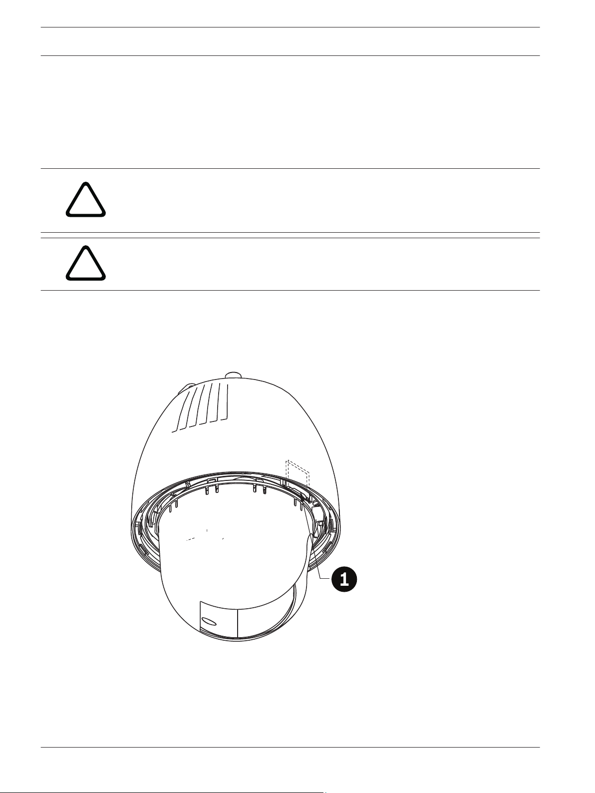
2. Locate the SD card slot (item one in the figure below).
Figure 5.1: Camera cross section with SD card slot
3. Orient the card so that the side with the golden contacts faces away from the dome and
towards the housing. The contacts should be at the top as you hold the SD card.
4. Slide the SD card into the slot. Press down the end of the SD cards until you hear a click
and the card locks into place.
2013.07 | 1.2.2 | F.01U.283.679 Operation Manual Bosch Security Systems
Page 21

AutoDome 7000 Series (IP and HD) Installing the Optional SD Card | en 21
5. Follow the steps in one of these sections (depending on the type of camera mount):
Replace the bubble in an in-ceiling housing, page 69 or Replace the bubble in a pendant
housing, page 69.
Bosch Security Systems Operation Manual 2013.07 | 1.2.2 | F.01U.283.679
Page 22
!
22 en | Mount Power Supply Box (Wall, Mast (Pole), and Corner Mounts) AutoDome 7000 Series (IP and HD)
6
Mount Power Supply Box (Wall, Mast (Pole), and Corner Mounts)
Before mounting the Power Supply Box, decide if you should wire the box through the holes in
the bottom or back of the box. If wiring the box through the back, move the two (2) seal plugs
to the bottom through the holes before mounting.
Notice!
Use 3/4-inch (20-mm) NPS fittings for the holes on the bottom and back of the box. Use 1/2inch (15-mm) NPS fittings for the side holes.
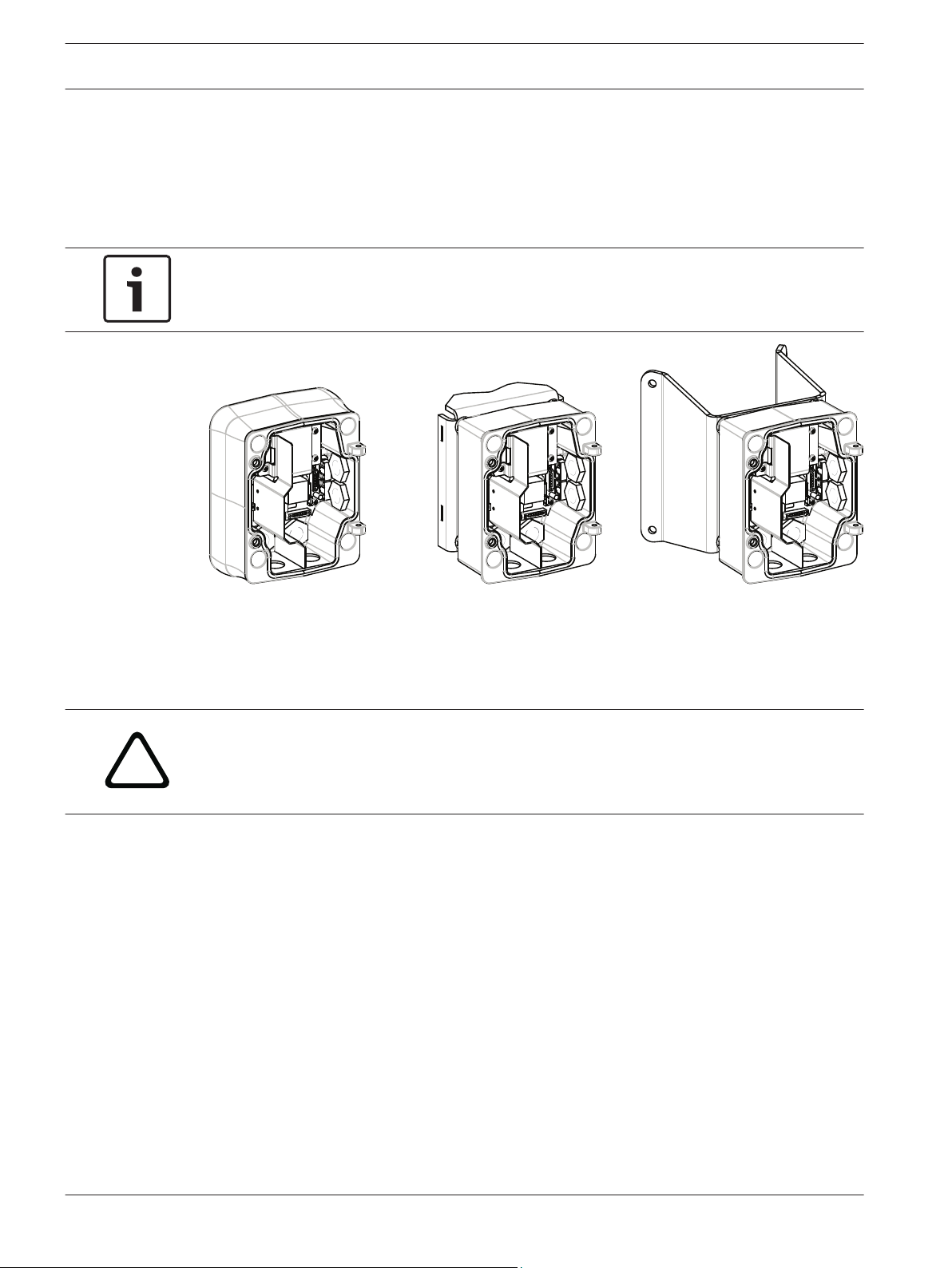
Figure 6.1: Power Supply Wall, Mast (Pole), and Corner Mounts
1. Use the wall mount template supplied in the packaging box to locate the four (4)
mounting holes for the Power Supply Box.
2. Drill four (4) holes for the mounting anchors. If installing outdoors, apply a weatherproof
sealant around each hole at the mounting surface.
Warning!
A stud diameter of 6.4 mm (1/4 inch) to 8 mm (5/16 inch) able to withstand a 120 kg (265 lb)
pull-out force is recommended. The mounting material must be able to withstand this pull out
force. For example, 19-mm (3/4-inch) minimum for plywood.
3. Place the Power Supply Box into the optional Trim Skirt.
4. Secure the Power Supply Box to the mounting surface.
For a Wall installation: Use four (4) corrosion-resistant, stainless steel studs (not
supplied). Then proceed to Step 5 below.
For a Corner installation: Secure the Corner Plate to the wall corner using four (4) studs
(not included). Then proceed to Step 5 below.
For a Mast or a pole installation: The metal straps included with the Mast mount
accommodate a pole with a diameter of 100–380 mm (4–15 in.). You must use a banding
tool (sold separately) for a mast or pole installation. Follow the instructions provided
with the banding tool to securely mount the Mast Plate to the pole. Contact your Bosch
Sales Representative to order Banding Tool P/N TC9311PM3T.
5. Secure the Power Supply Box to the Corner Plate or Mast Plate using the four (4) 3/8 x
1-3/4-inch bolts and split lock washers (supplied).
6. Attach 3/4-inch (20-mm) NPS watertight, earth-grounded conduit pipe fittings (not
supplied) to the bottom or back holes of the Power Supply Box through which you will
run the power, video, and control data wires.
2013.07 | 1.2.2 | F.01U.283.679 Operation Manual Bosch Security Systems
Page 23

!
AutoDome 7000 Series (IP and HD) Mount Power Supply Box (Wall, Mast (Pole), and Corner Mounts) | en 23
Warning!
For units intended to be installed outdoors: All wiring (power and I/O cabling) connecting to
the unit must be routed separately inside different permanently earthed metal conduits (not
supplied).
Bosch Security Systems Operation Manual 2013.07 | 1.2.2 | F.01U.283.679
Page 24
!
24 en | Installing the Pendant Arm Wall, Corner, and Mast (Pole) Mounts AutoDome 7000 Series (IP and HD)
7
7.1
7.2
Installing the Pendant Arm Wall, Corner, and Mast (Pole) Mounts
Description
This chapter details how to install an AUTODOME to a Wall, Corner, or Mast (pole) mount. Any
differences to the installation between these two mounting systems are noted.
Route Wires and Attach Connectors
Notice!
If you plan to route the power through an intermediate power supply box, refer to Route
Power through Intermediate Power Supply Box, page 28.
Power wires must be routed to the left (front) side of the Power Supply Box through a
separate electrically earth-grounded conduit. All video, control, and alarm wires must be
routed through a second electrically earth-grounded conduit to the right side of the box.
Warning!
External interconnecting cables are to be installed in accordance to NEC, ANSI/NFPA70 (for
US application) and Canadian Electrical Code, Part I, CSA C22.1 (for CAN application) and in
accordance to local country codes for all other countries.
Branch circuit protection incorporating a 20 A, 2-pole Listed Circuit Breaker or Branch Rated
Fuses are required as part of the building installation. A readily accessible 2-pole disconnect
device with a contact separation of at least 3 mm (0.12 in.) must be incorporated.
Making the Connections
Notice!
Refer to the Connection, page 70 chapter for wire specifications and distances.
1. Route all video, control, and alarm wires through the earth-grounded conduit fitting on
the right side of the power box.
2. Route the high voltage 115/230 VAC lines through the earth-grounded conduit fitting on
the left side of the box. The Power Supply Box with a transformer comes with a barrier
that separates the high voltage side on the left, from the low voltage 24 VAC side on the
right.
3. Cut and trim all wires with sufficient slack to reach their connector terminals in the box,
but not so long as to be pinched by or to obstruct closing the Pendant Arm. Refer to the
image above for the connector locations.
4. Attach the supplied 3-pin Power Plug to the incoming power wires. Refer to connector
P101 for wire connections.
5. If audio input and/or audio output is required, attach the supplied 6-pin SERIAL
COMMUNICATIONS to P106 in the Power Supply Box. Refer to connector P106 in the
Power Supply Box Connections section below.
6. Attach an RJ45 plug to the incoming Ethernet cable.
Connecting Alarm Inputs and Outputs
4 To connect alarm inputs and outputs, attach the supplied 6-pin Alarms In and the 4-pin
Alarms Out connector plugs with flying lead wires to the appropriate incoming alarm
wires. Alarm Out 4 is a relay.
2013.07 | 1.2.2 | F.01U.283.679 Operation Manual Bosch Security Systems
Page 25
1
1
2
3
4
5
6
2
3
4
N.O. COM N.C. A1 GND A2
1
PIN
PIN
P102
P103
P104
WHITE
ORANGE
BROWN
GREEN
WHITE
ORANGE
BROWN
GREEN
YELLOW
BLUE
2
3
4
5
6
7
AutoDome 7000 Series (IP and HD)
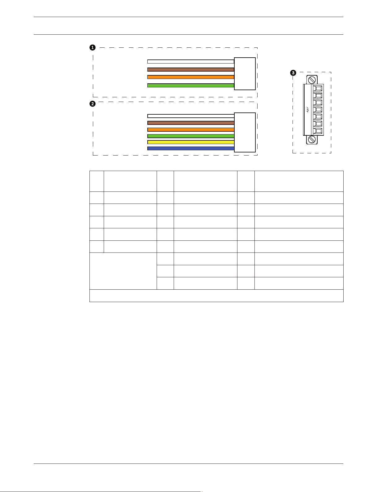
Figure 7.1: Alarm and relay connectors
1
4-pin Alarm
Connector (P102)
Pin Description Pin Description Pin Description
Installing the Pendant Arm Wall, Corner, and Mast (Pole) Mounts | en 25
2 6-pin Alarm In
3 7-pin Relay Connector (P104)
Connector (P103)
1 Alarm Out 1 1 Alarm in 3 1 Alarm Out 4 Normally Open
2 Alarm Out 2 2 Alarm in 4 2 Alarm Out 4 COM
3 Alarm Out 3 3 Alarm in 5 3 Alarm Out 4 Normally Closed
4 Alarm Ground 4 Alarm in 6 4 Earth Ground
5 Alarm in 7 5 Analog Alarm 1
6 Alarm Ground 6 Analog Alarm 2
7 Ground
For in-ceiling mount only: Low Voltage TTL (3.3V) can also be used.
4 If you are connecting supervised alarms and relays, attach the supplied 7-pin Relay
Connector to the appropriate incoming wires. Refer to Make Connections in the Power
Supply Box, page 32 for additional information.
Power Supply Box Connections
The following figure is a detailed illustration of the Pendant Arm Power Supply Box, which
includes the fuse specifications.
Bosch Security Systems Operation Manual 2013.07 | 1.2.2 | F.01U.283.679
Page 26
TRANSFORMER
(115/230VAC
MODELS)
P101
1 2 3
6 5 4 3 2 1 6 5 4 3 2 1
P106
XF102 XF103
XF101
J102
J101
J101
J101
J101
J101
J101
J101
(LED)
P107
5 4 3 2 1
GND TXD RXD C+ C-
P105
GND TXD RXD C+ C-
HTR DOME
a
LINE NC NEUT
!
26 en | Installing the Pendant Arm Wall, Corner, and Mast (Pole) Mounts AutoDome 7000 Series (IP and HD)
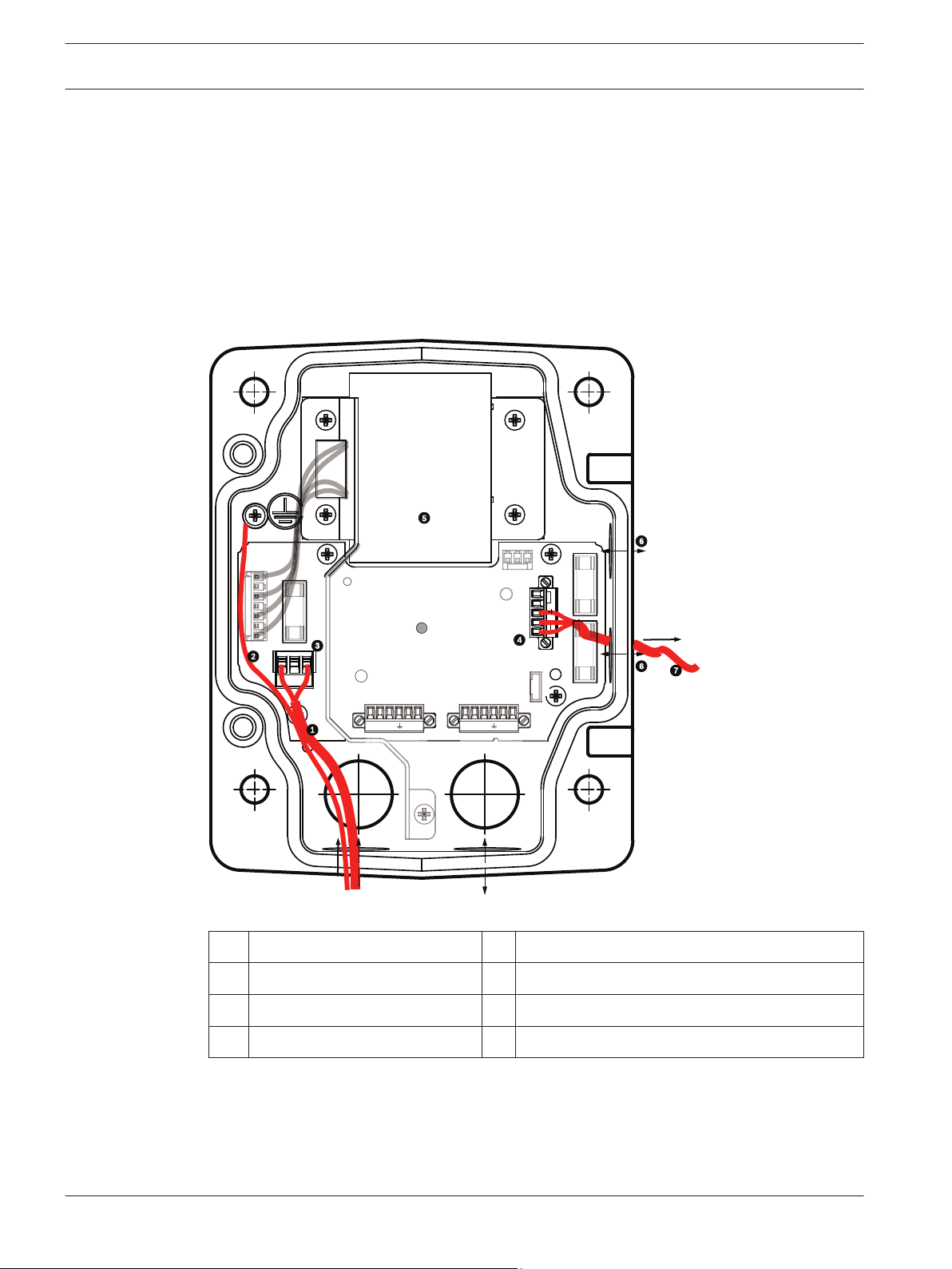
Figure 7.2: Pendant arm power supply box
Ground Screw 7 P101 Connector; Power In (120 VAC / 220
1
VAC)
2 From Harness (Nexus cable bundle) 8 P106 Connector; Control In/Out for external
audio input and output
3 In/Out; 1/2 in. (15 mm) NPS Fitting 9 P105 Connector; Audio to camera
4 Ethernet connector 10 Power In; 3/4 in. (20 mm) NPS Fitting
5 P107 Connector; 24 VAC to camera 11 Audio Input/Output; 3/4 in. (20 mm) NPS
Fitting (labeled “SERIAL COMMUNICATIONS”)
6 In/Out; 1/2 in. (15 mm) NPS Fitting
Warning!
In earlier Bosch AUTODOME cameras, cable 8 in the ARM mount is labeled “Control In/Out”
and was used for external RxD/TxD and Biphase communications. In the AUTODOME 7000
Series cameras: If you are mounting an AUTODOME 7000 Series camera to an ARM mount
that was wired for an earlier model of Bosch AUTODOME, you must either re-wire cable 8 to
be audio input and output, or disconnected it from the power supply.
Cables/wires that are routed through number 2 in the illustration above come from the Nexus
cable bundle that is in the pendant Arm.
2013.07 | 1.2.2 | F.01U.283.679 Operation Manual Bosch Security Systems
Page 27
!
!
AutoDome 7000 Series (IP and HD) Installing the Pendant Arm Wall, Corner, and Mast (Pole) Mounts | en 27
Fuse Specifications
Volts XF101 Mains XF102 Camera XF103 Heater
24 V T 5.0 A T 2.0 A T 3.15 A
115 V T 1.6 A T 2.0 A T 3.15 A
230 V T 0.8A T 2.0 A T 3.15 A
Warning!
Fuse replacement by qualified service personnel only. Replace with same type fuse.
Fuse Specifications
Volts XF101 Mains XF102 Camera XF103 Heater
24 V T 5.0 A T 2.0 A T 3.15 A
115 V T 1.6 A T 2.0 A T 3.15 A
230 V T 0.8A T 2.0 A T 3.15 A
The following table lists the Power Supply Box connectors:
No. Connector Pin 1 Pin 2 Pin 3 Pin 4 Pin 5 Pin 6
Ground Grounding Screw
P101 115/230 VAC or
24 VAC Power In
P106 SERIAL
COMMUNICATIONS
P107 24 VAC Power
(Arm Harness)
Table 7.1: Power Supply Box Connections
Notice!
Pins for P106 1, 2, 4, and 5 are used for audio input and output for AUTODOME 7000 Series
cameras; however, their labels are still those of previous versions of analog AUTODOME
cameras.
Line NC Neutral
CODE(Audio IN-,
Audio in
signal
ground)
Camera
24 VAC
CODE+
(Audio IN+)
Camera
24 VAC
Earth GND
(Ground)
(Audio)
Earth
Ground
RXD
(Audio OUT+)
Heater
(24 VAC)
TXD
(Audio OUT-;
Audio out
signal
ground)
Heater
(24 VAC)
Signal
GND
(Ground)
Warning!
For units intended to be installed outdoors: All wiring (power and I/O cabling) connecting to
the unit must be routed separately inside different permanently earthed metal conduits (not
supplied).
Bosch Security Systems Operation Manual 2013.07 | 1.2.2 | F.01U.283.679
Page 28
GND
T
XD RXD
C+
C-
GND
T
XD RXD
C+
C-
P101
1 2 3
6 5 4 3 2 1
6 5 4 3 2 1
6 5 4 3 2 1
P106
P105
P107
XF102 XF103
XF101
5 4 3 2 1
J102
J101
(LED)
VG4-PSU1 / VG4-PSU2
HTR DOME
LINE NC NEUT
28 en | Installing the Pendant Arm Wall, Corner, and Mast (Pole) Mounts AutoDome 7000 Series (IP and HD)
7.3
Route Power through Intermediate Power Supply Box
You may route the main power supply through a VG4-PSU1 (120 V transformer) or through a
VG4-PSU2 (230 V transformer) Power Supply Box before connecting the power to a VG4-PA0
(24 V, no transformer) Power Supply Box. The main issue with this configuration is that the 5pin power out connector from the VG4-PSU1 or VG4-PSU2 does not match to the 3-pin power
input of the VG4-PA0 power supply. The illustration below depicts:
– A VG4-PSU1/VG4-PSU2 Power Supply Box.
– The main power supply connected to the P101 connector and to the grounding screw.
– The 24 VAC power out wire connected to the P107 heater power connectors.
Figure 7.3: VG4-PSU1/VG4-PSU2
120/230 VAC Power In 5 Transformer
1
2 Ground Wire 6 In/Out Conduit (1/2 in. [15 mm] NPS Fitting
3 P101 Connector 7 24 VAC Power Out to VG4-PA0
4 P107 Connector
To properly wire the incoming high voltage and the outgoing low voltage lines, refer to this
table:
2013.07 | 1.2.2 | F.01U.283.679 Operation Manual Bosch Security Systems
Page 29
P101
1 2 3
LINE NC NEUT
P107
5 4 3 2 1
HTR DOME
AutoDome 7000 Series (IP and HD) Installing the Pendant Arm Wall, Corner, and Mast (Pole) Mounts | en 29
No. Connector Pin 1 Pin 2 Pin 3 Pin 4 Pin 5 Pin 6
Ground Grounding Screw
P101 120/230 VAC Power In Line NC Neutral
P107 24 VAC Power Out Earth Ground Heater
(24 VAC)
Table 7.2: VG4-PSU1/VG4-PSU2 Power Supply Box Connections
1. Route the high voltage 120/230 VAC lines through the earth-grounded conduit fitting on
the left side of the box. The Power Supply Box with a transformer comes with a barrier
that separates the high voltage side on the left, from the low voltage 24 VAC side on the
right.
2. Cut and trim the high voltage 120/230 VAC power and ground wires with sufficient slack
to reach their connector terminal in the box, but not so long as to be pinched by or to
obstruct closing the cover door.
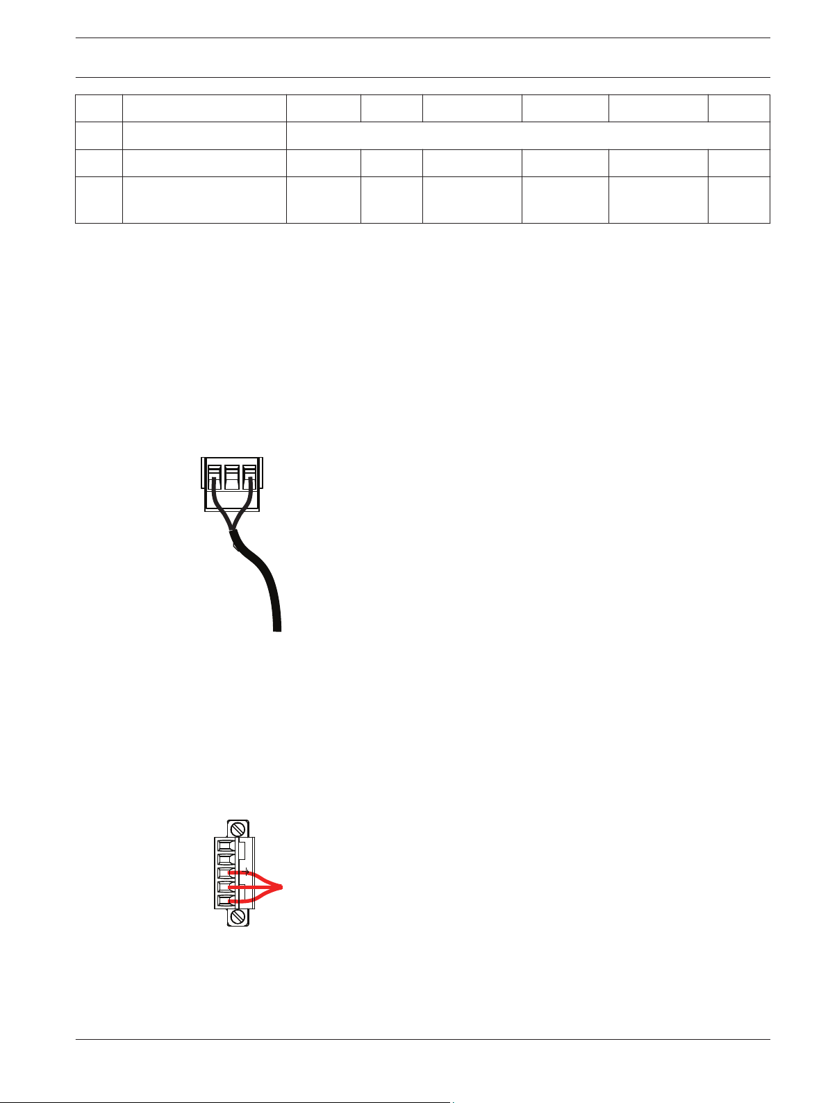
3. Attach the supplied 3-pin power plug to the incoming high voltage power wires in the
box. Refer to connector P101 in the table above and to the image below for an illustration
of these connections:
Heater
(24 VAC)
Figure 7.4: Incoming 115/230 VAC power supply
4. Attach the ground wire to the grounding screw.
5. Connect three wires to the P107 Power Out connector to route the 24 VAC power supply
to the VG4-PA0 Power Supply Box.
Connect the first wire to pin 5 (HN: Heater Neutral) connector.
Connect the second wire to pin 4 (HL: Heater Line) connector.
Connect the third wire to pin 3 (Earth Ground) connector.
Refer to connector P107 in the table above and to the image below for an illustration of
these connections:
Figure 7.5: Outgoing 24 VAC power supply
Bosch Security Systems Operation Manual 2013.07 | 1.2.2 | F.01U.283.679
Page 30
!
GND
XD
XD
C+
C-
GND
XD
XD
C+
C-
P101
1 2 3
6 5 4 3 2 1
6 5 4
6 5 4 3 2 1
P106
P105
P107
XF102 XF103
XF101
5 4 3 2 1
J102
J101
(LED)
HTR DOME
24V NC 24V
30 en | Installing the Pendant Arm Wall, Corner, and Mast (Pole) Mounts AutoDome 7000 Series (IP and HD)
Warning!
Ensure that you connect the outgoing power supply wires to the P107 heater connectors (HN
and HL). The heater power (XF103) fuse can handle a higher amperage (3.15 A) than the
camera power (XF102) fuse (2.0 A).
6. Route the 24 VAC outgoing power supply wires into the VG4-PA0 power supply box
through the conduit fitting on the left side of the box.
7. Cut and trim the 24 VAC power and ground wires with sufficient slack to reach their
connector terminal in the box, but not so long as to be pinched by or to obstruct closing
the cover door.
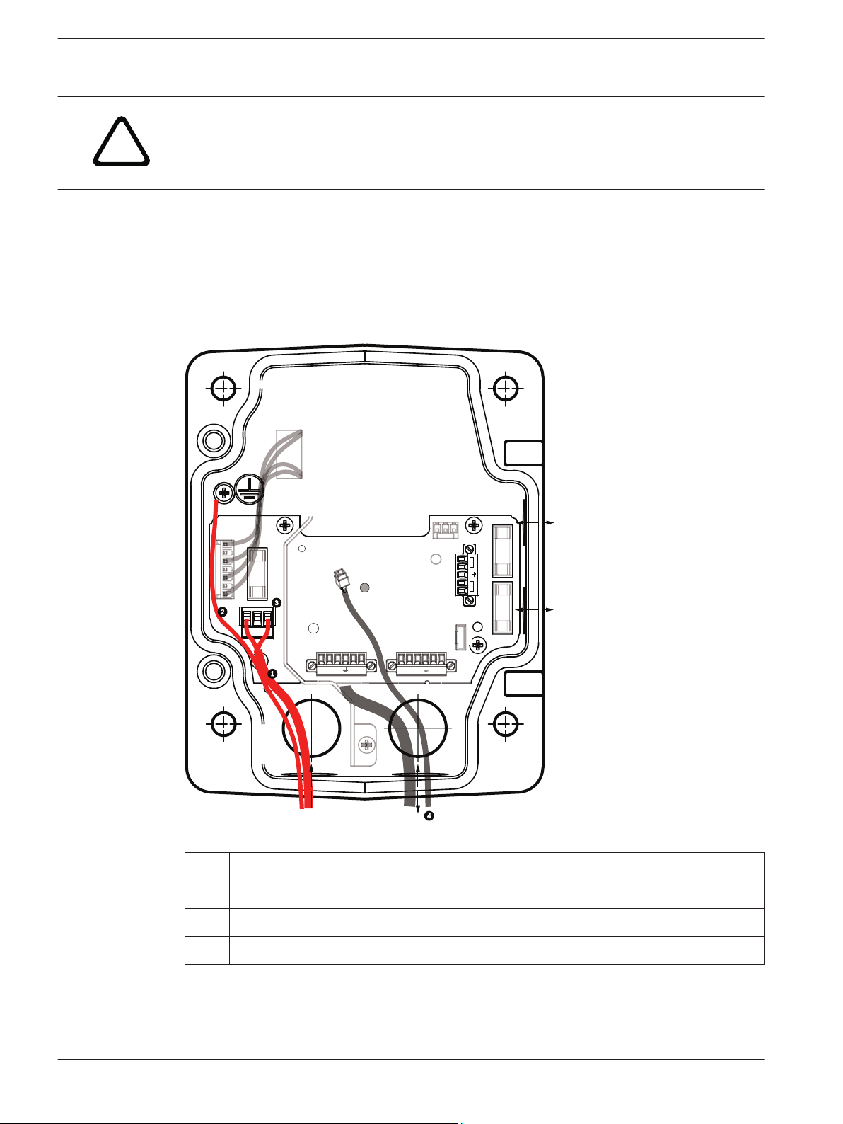
8. Attach the supplied 3-pin power plug to the incoming 24 VAC power wires in the box, as
illustrated below.
Figure 7.6: VG4-PA0 Power Supply Box
Incoming 24 VAC Power Supply Wires (from VG4-PSU1/VG4-PSU2 power supply box)
1
2 Ground Wire
3 P101 Connector
4 Control Data and Video In/Out Wires
4 Follow the instructions in Attach Pendant Arm to Power Supply Box, page 31 to continue
the installation.
2013.07 | 1.2.2 | F.01U.283.679 Operation Manual Bosch Security Systems
Page 31

!
AutoDome 7000 Series (IP and HD) Installing the Pendant Arm Wall, Corner, and Mast (Pole) Mounts | en 31
7.4
Attach Pendant Arm to Power Supply Box
The bottom hinge pin of the Pendant Arm is provided with a Hinge Pin Stop to hold the hinge
open while attaching the arm to the Power Supply Box.
1. Compress the bottom hinge pin by pushing the pin lever downward and rotating it behind
the Hinge Pin Stop.
Figure 7.7: Pendant Arm to Power Box Hinge Alignment
2. Open the top hinge by pushing its pin lever up and holding it.
Notice!
Both Hinge Pins must be fully compressed to open (unlock) the hinges of the Pendant Arm
and before proceeding to the next step.
3. While continuing to hold the top hinge pin open and align the top and bottom hinges of
the Pendant Arm to their mating points on the Power Supply Box. See the illustration
above.
4. Once you have aligned the hinges, release the top hinge pin to engage its mating hinge on
the power box. Then release the bottom hinge pin from the Hinge Pin Stop to lock the
Pendant Arm to the Power Supply Box.
Warning!
Serious injury or death can occur if the hinge pins of the Pendant Arm are not fully engaged
(locked) to the Power Supply Box. Exercise caution before releasing the Pendant Arm.
Bosch Security Systems Operation Manual 2013.07 | 1.2.2 | F.01U.283.679
Page 32

1 2 3
32 en | Installing the Pendant Arm Wall, Corner, and Mast (Pole) Mounts AutoDome 7000 Series (IP and HD)
7.5
Make Connections in the Power Supply Box
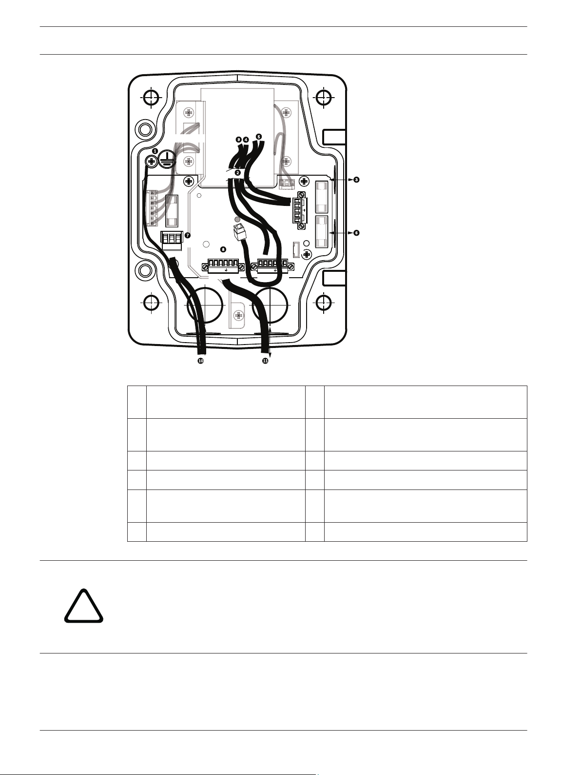
Figure 7.8: Pendant Arm connections to Power Supply Box
1. Attach the earth ground wire (item 1 in the illustration above) to the grounding screw on
the left side of the power box.
2. Connect the 6-pin Control In/Out Plug, installed previously, to its mating connector P106
in the power box.
3. Connect the 6-pin Control to Dome Plug from the Pendant Connector Harness to its
mating connector P105 in the power box.
4. Connect the 5-pin, 24 VAC to Dome Plug from the Pendant Connector Harness to its
corresponding color mating connector P107 on the right side of the box.
5. To connect alarm inputs and relay outputs, connect the 4-pin Alarms Out, the 6-pin
Alarms In, and the 7-pin Relay connectors from the Pendant Connector Harness to their
mating connectors, installed previously, to the incoming alarm wires.
6. Connect the 3-pin Power In Plug, installed previously, to its mating connector P101 on
the left side of the box.
7. Connect the incoming RJ45 video connector, installed previously, to its mating connector
from the Pendant Connector Harness.
8. Attach the grounding strap of the Pendant Arm to the Power Supply Box.
9. After making the harness connections to the Power Supply Box, rotate the Pendant Arm
to close and seal the Power Supply Box and tighten the two (2) captive screws to
10‑12 N-m (90-105 in.-lbs).
10. Refer to Attach Pendant to Arm and Tighten, page 37 to continue the installation
procedure.
Notice!
2013.07 | 1.2.2 | F.01U.283.679 Operation Manual Bosch Security Systems
After all wiring is complete, close the cover door and tighten the two (2) captive screws on
the cover door to 10-12 N-m (90-105 in.-lbs) to ensure the Power Supply Box is watertight.
Page 33

!
!
AutoDome 7000 Series (IP and HD) Installing the Pendant Arm Wall, Corner, and Mast (Pole) Mounts | en 33
7.6
Installing the VGA-PEND-WPLATE
This section provides instructions to install a wall, corner, or mast mount with the VGA-PENDWPLATE Mounting Plate instead of a Power Supply Box.
Caution!
You must route the main power supply through a 120/230 VAC transformer (VG4-PSU1 or
VG4-PSU2 power supply box) before connecting the power to a 24 VAC AUTODOME camera.
Warning!
A stud diameter of 6.4 mm (1/4 inch) to 8 mm (5/16 inch) able to withstand a 120 kg (265 lb)
pull-out force is recommended. The mounting material must be able to withstand this pull out
force. For example, 19-mm (3/4-inch) minimum for plywood.
1. For a Corner installation:
Secure the Corner Plate to the wall corner using four (4) studs (not included).
Secure the Mounting Plate to the Corner Plate using the four (4) 3/8 x 1-3/4-inch bolts
and split lock washers (supplied).
2. For a Mast or pole installation:
The metal straps included with the Mast mount accommodate a pole with a diameter of
100–380 mm (4–15 in.). You must use a banding tool (sold separately) for a mast or pole
installation. In addition, you must obtain a 3/4 in. (20-mm) right angle conduit connector
through which you route the wires that connect to the pendent arm.
Follow the instructions provided with the banding tool to securely mount the Mast Plate
to the pole. Contact your Bosch Sales Representative to order Banding Tool P/N
TC9311PM3T.
Secure the Mounting Plate to the Mast Plate using the four (4) 3/8 x 1-3/4-inch bolts and
split lock washers (supplied).
Remove one of the rubber gaskets from the Mounting Plate.
Once the Mounting Plate (item 1, below) is attached to the Mast Plate (item 2), connect
the right angle conduit (item 3) to the Mounting Plate through the empty conduit hole as
shown below:
Bosch Security Systems Operation Manual 2013.07 | 1.2.2 | F.01U.283.679
Page 34

en | Installing the Pendant Arm Wall, Corner, and Mast (Pole) Mounts AutoDome 7000 Series (IP and HD)
34
3. Ensure that the mounting plate is secure.
Attach the Pendant Arm to the Mounting Plate
The bottom hinge pin of the Pendant Arm is provided with a Hinge Pin Stop to hold the hinge
open while attaching the arm to the Mounting Plate.
1. Compress the bottom hinge pin by pushing the pin lever downward and rotating it behind
the Hinge Pin Stop.
Figure 7.9: Connect Pendant Arm to Mounting Plate
2. Open the top hinge by pushing its pin lever up and holding it.
Note: Both Hinge Pins must be fully compressed to open (unlock) the hinges of the
Pendant Arm and before proceeding to the next step.
3. While continuing to hold the top hinge pin open, align the top and bottom hinges of the
Pendant Arm to their mating points on the Mounting Plate.
2013.07 | 1.2.2 | F.01U.283.679 Operation Manual Bosch Security Systems
Page 35

AutoDome 7000 Series (IP and HD) Installing the Pendant Arm Wall, Corner, and Mast (Pole) Mounts | en 35
4. Once you have the hinges aligned, release the top hinge pin to engage its mating hinge on
the Mounting Plate. Then release the bottom hinge pin from the Hinge Pin Stop to lock
the Pendant Arm to the Mounting Plate.
Route and Connect Wires to a Power Supply Box
The illustration below depicts the power and control cables connected to the Pendant Arm:
Figure 7.10: Pendant Arm Cables
Cable Cable
1 Grounding Strap (black) 5 UTP Video/Ethernet (blue)
2 24 VAC Power (red) 6 Alarm Outputs (white)
3 Relay Contacts (yellow) 7 Alarm Inputs (gray)
4 Coax Video (black)
(Not applicable for AUTODOME
7000 Series cameras)
8 Serial Communications (green)
Used for Audio Input/Output in
AUTODOME 7000 Series.
Notice!
Refer to the Connection, page 70 chapter for wire specifications and distances.
1. Route all incoming wires through one of the earth-grounded conduits at the bottom of the
Mounting Plate. For a mast mount, route all wires through the right-angle conduit.
2. Attach the water-tight plug to the other conduit.
3. Attach the grounding spade terminal (item 1, below) to one of the spade terminals inside
the Mounting Plate.
Bosch Security Systems Operation Manual 2013.07 | 1.2.2 | F.01U.283.679
Page 36

en | Installing the Pendant Arm Wall, Corner, and Mast (Pole) Mounts AutoDome 7000 Series (IP and HD)
36
Figure 7.11: Mounting Plate - Inside Detail
Ref.
Description
1 Grounding lug with two spade terminals
2 Earth ground lug with crimp ring terminal
3 Wire input conduit holes
4. Connect the incoming 24 VAC power wires to the 5-pin, 24 VAC Power In mating
connector (supplied with the Mounting Plate kit) for the camera and for the Heater.
5. Attach the grounding spade from the 5-pin mating connector to the other spade terminal
inside the mounting plate.
6. Attach the 5-pin Power In mating connector to the 24 VAC Power cable (cable 2)
connected to the pendant.
7. Remove the mating connector from the Relay Contacts cable (cable 3).
8. Connect the incoming relay contact wires to the mating connector. Then, reattach the
mating connector to the Relay Contacts cable.
9. Attach an RJ45 plug to the incoming UTP cable.
10. Connect the incoming RJ45 video connector, installed previously, to the UTP Video/
Ethernet cable (cable 5).
11. Connect the outgoing alarm wires to the flying leads coming from the 4-pin Alarm Outputs
cable (cable 6).
12. Connect the incoming alarms wires to the flying leads coming from the 6-pin Alarm Inputs
cable (cable 7).
13. Connect the incoming serial communication wires to the 6-pin mating connector supplied
with the VGA-PEND-WPLATE kit. Refer to the Power Supply Box Connections table above
for details.
2013.07 | 1.2.2 | F.01U.283.679 Operation Manual Bosch Security Systems
Page 37

AutoDome 7000 Series (IP and HD) Installing the Pendant Arm Wall, Corner, and Mast (Pole) Mounts | en 37
14. Attach the 6-pin serial communication mating connector to the Serial Communications
cable (cable 8).
15. Connect the Earth ground wire, if available, to the crimp ring terminal inside the
Mounting Plate.
Note: The Earth ground is not provided with the VGA-PEND-WPLATE kit; it is a ground
connection made at the installed location.
16. After making the harness connections to the Mounting Plate, rotate the Pendant Arm to
close and tighten the two (2) captive screws to 10‑12 N-m (90-105 in.-lbs).
Notice!
After all wiring is complete, close the cover door and tighten the two (2) captive screws on
the cover door to 10-12 N-m (90-105 in.-lbs).
7.7
Attach Pendant to Arm and Tighten
Notice!
Before attaching the AUTODOME Pendant, visually inspect the dome and arm connectors for
any blocked pin holes or bent pins.
1. Tilt the bottom of the dome toward the pendant arm base and place the mounting hook,
located on top of the dome housing, over the recessed hinge pin of the arm.
Bosch Security Systems Operation Manual 2013.07 | 1.2.2 | F.01U.283.679
Page 38

a
b
!
38 en | Installing the Pendant Arm Wall, Corner, and Mast (Pole) Mounts AutoDome 7000 Series (IP and HD)
Figure 7.12: Attach Pendant to Arm
Tilt up.
1
2 Hook and drop.
2a Recessed Hinge Pin
2b Dome Connector
3 Rotate down to engage dome connector.
4 Tighten the two (2) mounting screws to a minimum torque of 10-12 N-m (90-105 in.-lbs).
2. Drop the dome housing down slightly to engage the dome housing hook on the Pendant
Arm hinge pin, allowing the dome to rotate around the pin.
3. Rotate the dome housing down to a vertical position and gently push upward to engage
the connector on top of the dome housing.
Caution!
If you feel any resistance when rotating the dome housing or when engaging the connector,
stop immediately and start over.
2013.07 | 1.2.2 | F.01U.283.679 Operation Manual Bosch Security Systems
Page 39

!
AutoDome 7000 Series (IP and HD) Installing the Pendant Arm Wall, Corner, and Mast (Pole) Mounts | en 39
4. Hold the Pendant housing in position while tightening the two (2) 5-mm Allen head
mounting screws on top of the housing to 10-12 N-m (90-105 in.-lbs).
Caution!
You must tighten the two mounting screws to a minimum torque of 10-12 N-m (90‑105 in.-lbs)
to ensure a proper seal between the arm and the housing.
Bosch Security Systems Operation Manual 2013.07 | 1.2.2 | F.01U.283.679
Page 40

!
40 en | Installing the Roof Parapet and Pipe Mounts AutoDome 7000 Series (IP and HD)
8
8.1
8.2
Installing the Roof Parapet and Pipe Mounts
Description
This chapter details how to install an AUTODOME camera to a Roof Parapet or to a Pipe
mount. Any differences to the installation between these two mounting systems are noted.
The VGA-ROOF-MOUNT is a stationary mount intended for rooftop parapet vertical walls. It is
made of light weight aluminum with a corrosion-resistant finish and is used for all Bosch
AUTODOME cameras up to a rated load of 29 kg (64 lb). This mount can be fitted to the inside
or outside of parapet walls and can swivel for ease of positioning and for servicing the camera.
Note that customers must purchase separately the VG4-A-9543 Pipe Mount to use on the end
of the VGA-ROOF-MOUNT.
The end of the Pipe Mount that is meant to terminate into an enclosure is intended to be fieldinstalled and shall be marked or provided with instructions that identify the equipment
necessary to maintain the environmental integrity of the enclosure. In order to maintain the
integrity of a Type 4X environment, the connected equipment must have a Type 4X
environmental rating. In order to maintain the integrity of a Type 4 environment, the
connected equipment must have a Type 4, Type 4X, Type 6, or Type 6P environmental rating.
Route Wires and Attach Connectors
Power wires must be routed to the left (front) side of the Power Supply Box through a
separate electrically earth-grounded conduit. All video, control, and alarm wires must be
routed through a second electrically earth-grounded conduit to the right side of the box.
Warning!
External interconnecting cables are to be installed in accordance to NEC, ANSI/NFPA70 (for
US application) and Canadian Electrical Code, Part I, CSA C22.1 (for CAN application) and in
accordance to local country codes for all other countries.
Branch circuit protection incorporating a 20 A, 2-pole Listed Circuit Breaker or Branch Rated
Fuses are required as part of the building installation. A readily accessible 2-pole disconnect
device with a contact separation of at least 3 mm (0.12 in.) must be incorporated.
There are two possible methods to route the video, control, and alarm wires:
Method One is to route the video, control, and alarm wires through the conduit fitting on the
right (front) side of the Power Supply Box and out to the AUTODOME Interface Board.
2013.07 | 1.2.2 | F.01U.283.679 Operation Manual Bosch Security Systems
Page 41

GND TXD RXD C+ C-GND TXD RXD C+ C-
P101
P106 P105
P107
XF102 XF103
XF101
5 4 3 2 1
J102
J101
(LED)
HTR DOME
LINE NC NEUT
AutoDome 7000 Series (IP and HD)
Installing the Roof Parapet and Pipe Mounts | en 41
Figure 8.1: VG4-A-PSU1 or VG4-A-PSU2 Power Supply Box
120 VAC/230 VAC Power In 6 Control Wire
1
Used for Audio input and output in
AUTODOME 7000 Series.
2 P101 Connector 7 24 VAC Power Out
3 Ground Connection 8 P107 Connector
4 Transformer 9 Earth-grounded conduit with power input
and earth-ground connection
5 Ethernet Wire 10 Earth-grounded conduit with Ethernet
video/control, audio input and output to
“head-end“ system
11 Earth-grounded conduit to camera
Method Two is to bypass the Power Supply Box and route the video, control, and alarm wires
directly to the Interface Board. You connect only the power wires inside the Power Supply
Box. All conduit and junction boxes used must be electrically earth-grounded.
Bosch Security Systems Operation Manual 2013.07 | 1.2.2 | F.01U.283.679
Page 42

GND TXD RXD C+ C-GND TXD RXD C+ C-
P101
P106 P105
P107
XF102 XF103
XF101
5 4 3 2 1
J102
J101
(LED)
HTR DOME
BNC
J102
P107 P101
P102
P103
P104
P106
J101
AGND
A7
A6
A5
A4
A3
AGND
OUT 3
OUT 2
OUT 1
P105
LINE NC NEUT
42 en | Installing the Roof Parapet and Pipe Mounts AutoDome 7000 Series (IP and HD)
Figure 8.2: VG4-A-PSU1 or VG4-A-PSU2 Power Supply Box Connected to Pipe Interface Board
VG4-A-PSU1/VG4-A-PSU2 Pipe Interface Board
1 120 VAC/230 VAC Power In 7 P101 Connector
2 P101 Connector 8 P107 Connector
3 Ground Connection 9 24 VAC Power In (to camera)
4 Transformer 10 Earth Ground
5 24 VAC Power Out 11 24 VAC Power In (to camera)
6 P107 Connector 12 24 VAC Power In (to Heater)
13 24 VAC Power In (to Heater)
14 Camera Power
15 Heater Power
Wiring the Power Supply Box
Notice!
Refer to the Connection, page 70 chapter for wire specifications and distances.
4 Route the high voltage 115/230 VAC lines through the earth-grounded conduit fitting on
the left side of the box.
Notice!
The Power Supply Box with transformer comes with a barrier that separates the high voltage
side on the left from the low voltage 24 VAC side on the right.
2013.07 | 1.2.2 | F.01U.283.679 Operation Manual Bosch Security Systems
Page 43

AutoDome 7000 Series (IP and HD) Installing the Roof Parapet and Pipe Mounts | en 43
1. Cut and trim the high voltage 115/230 VAC power and ground wires with sufficient slack
to reach their connector terminal in the box, but not so long as to be pinched by or to
obstruct closing the Cover Door.
2. Attach the supplied 3-pin Power Plug to the incoming high voltage power wires in the
box. Refer to connector P101 in the Power Supply Box Connections section below.
3. Route the Ethernet cable out to where the camera will be mounted.
4. Route the low power 24 VAC wires from the right side of the Power Supply Box out to
where the camera will be mounted. Attach the supplied 5-pin 24 VAC Dome plug to the
wire ends inside the box. Refer to connector P107 in the Power Supply Box Connections
section below.
Notice!
All video, control, and alarm wires either pass through the Power Supply Box or by-pass it and
connect directly to the Pipe Interface Board.
Wiring the Fiber Optic Model
If installing a Fiber Optic model, follow these steps:
Notice!
Refer to the Connection, page 70 chapter for fiber optic specifications.
For instructions on installing a fiber optic module into a power supply box, see the VG4 Fiber
Optic Media Converter Installation Guide that ships with the module.
1. Bring the fiber optic cable (item 3 in the figure below) into the right side of the power
supply box.
2. Connect the fiber optic cable to the port for the SFP module (item 2 in the figure below).
3. Connect the RJ45 plug of the cable to the RJ45 socket (item 1 in the figure below) on the
fiber optic module in the power supply box.
4. Route the control wires from the Power Supply to the Pipe Interface Board. Then attach
the supplied six (6) pin control data connector to the wires in the Power Supply Box.
Refer to Wire the Pipe Interface Board, page 50.
Bosch Security Systems Operation Manual 2013.07 | 1.2.2 | F.01U.283.679
Page 44

GND TXD RXD C+ C-
P101
P106
XF102 XF103
XF101
5 4 3 2 1
J102
J101
(LED)
HTR DOME
24V NC 24V
en | Installing the Roof Parapet and Pipe Mounts AutoDome 7000 Series (IP and HD)
44
Figure 8.3: Fiber Optic Ethernet Module installed
RJ45 Ethernet socket
1
2 Port for SFP module (sold separately)
3 Fiber Optic cable (user-supplied)
Power Supply Box Connections
The following figure is a detailed illustration of the Roof or Pipe Mount Power Supply Box,
which includes the fuse specifications.
2013.07 | 1.2.2 | F.01U.283.679 Operation Manual Bosch Security Systems
Page 45

C
ONTRO
L
T
O DOM
E
C
ONTRO
L
IN/OUT
GND
GND
GND
T
XD R
XD
C+ C-
P101
1 2 3
6 5 4 3 2 1
P106
P105
P107
XF102 XF103
XF101
5 4 3 2 1
J102
J101
J101
J101
J101
J101
J101
J101
J101
J101
J101
(LED)
6 5 4 3 2 1
GND
GND
GND
T
XD RXD
C+
C-
HTR DOME
LINE NC NEUT
!
AutoDome 7000 Series (IP and HD) Installing the Roof Parapet and Pipe Mounts | en 45
Figure 8.4: Power Supply Box Connections
Ground Screw 5 Power In
1
2 Transformer (115/230 VAC Modes) 6 In/Out; 1/2 in. (15 mm) NPS Fitting
3 In/Out to camera 7 Power In; 3/4 in. (20 mm) NPS Fitting
4 24 VAC to Dome Interface Board 8 Control Data and Video In/Out; 3/4 in. (20 mm)
NPS Fitting
Warning!
Fuse replacement by qualified service personnel only. Replace with same type fuse.
Fuse Specifications
Volts XF101 Mains XF102 Camera XF103 Heater
24 V T 5.0 A T 2.0 A T 3.15 A
115 V T 1.6 A T 2.0 A T 3.15 A
230 V T 0.8A T 2.0 A T 3.15 A
The following table lists the Power Supply Box connectors:
Bosch Security Systems Operation Manual 2013.07 | 1.2.2 | F.01U.283.679
Page 46

GND T XD R XD C+ C- GND T XD R XD C+ C-
90
o
HTR DOME
LINE NC NEUT
46 en | Installing the Roof Parapet and Pipe Mounts AutoDome 7000 Series (IP and HD)
No. Connector Pin 1 Pin 2 Pin 3 Pin 4 Pin 5 Pin 6
Ground Grounding Screw
P101 115/230 VAC or
Line NC Neutral
24 VAC Power In
P107 24 VAC Power to
Dome Plug
Table 8.1: Power Box Connections
8.3
Dome
24 VAC
Attach Cover Door to Power Supply Box
1. Compress the bottom hinge pin by pushing the pin lever down and then rotate it behind
the Hinge Pin Stop. The power box Cover Door provides a Hinge Pin Stop to hold the
bottom hinge open while attaching the door.
Dome
24 VAC
Earth Ground Heater
(24 VAC)
Heater
(24 VAC)
Figure 8.5: Align Cover Door Hinge to Power Box
Power Supply Box 5 Hold Hinge Pin Open
1
2 Cover Door 6 Open Position
3 Align Top Hinge 7 Hinge Pin Stop
4 Align Bottom Hinge
2. Open the top hinge by pushing its pin lever outward and holding it open.
Note: Both Hinge Pins must be fully compressed to open (unlock) the female hinges of
the Cover Door before proceeding to the next step.
3. While holding the top hinge pin open, position the Cover Door to the Power Supply Box
and align its hinges.
4. When the hinges are aligned, release the top hinge pin to engage its mating hinge on the
power box. Then release the bottom hinge pin from the Hinge Pin Stop to complete
attaching the Cover Door to the Power Supply Box.
2013.07 | 1.2.2 | F.01U.283.679 Operation Manual Bosch Security Systems
Page 47

AutoDome 7000 Series (IP and HD) Installing the Roof Parapet and Pipe Mounts | en 47
Notice!
After all wiring is complete, close the cover door and tighten the two (2) captive screws on
the cover door to 10-12 N-m (90-105 in.-lbs) to ensure the Power Supply Box is watertight.
8.4
Installing the VGA-ROOF-MOUNT
This section details the installation steps for the Roof Parapet Mount. If you are installing a
pipe mount, refer to Installing the VG4-A-9543 Pipe Mount, page 49 for instructions.
Figure 8.6: VGA-ROOF-MOUNT
1. Determine the wall location on the roof for the camera and use the Parapet wall mount
bracket as a template to mark the hole locations.
Notice!
Allow enough room below the Parapet Mount Bracket to route the video, control and alarm
wires up through the Parapet arm. In certain installations you may have to lift the Parapet arm
for the camera to clear the top of the wall when it is swung into position. Provide enough
slack in the wires to rotate the pipe arm over the roof and back when camera maintenance is
required.
2. Prepare the mounting surface for the type of fastener by drilling holes for the mounting
anchors as required.
Figure 8.7: Parapet Wall Mount Bracket and Roof Mount Plate
1 Pipearm 4 Apply sealant around each fastener hole
2 Parapet Wall Bracket 5 Roof Mount Plate
3 3/8-16 SS Hex Head Bolt
(supplied)
Bosch Security Systems Operation Manual 2013.07 | 1.2.2 | F.01U.283.679
6 Use a minimum of six (6) fasteners (not
supplied). Eight (8) fastener holes shown.
Page 48

!
48 en | Installing the Roof Parapet and Pipe Mounts AutoDome 7000 Series (IP and HD)
Notice!
Fasteners are not supplied with the Roof Parapet Mount Kit since it depends on the material
to which it is attached. The material must accommodate a minimum pull out strength of 275
kg (600 lbs). For example, 19 mm (3/4 inch) minimum for plywood. Fasteners can include
bolts, studs, or lag bolts. All fasteners must be made of corrosion-resistant stainless steel,
with a diameter of 10 mm (3/8 inch).
All bolts must fully extend through the mounting surface and be secured with a flat washer,
lock washer and a nut. All studs must be anchored to concrete or welded to a steel backing
plate. Anchor bolts can be used for blind structures where there is no access to the rear.
3. Apply a weatherproof sealant around each fastener hole at the mounting surface.
4. Attach the Parapet Wall Bracket using at least six (6) stainless steel fasteners, three (3)
on each side (the bracket has eight (8) holes). Be careful not to over tighten the fasteners
because it may strip the threads. If attaching the parapet mount to a flat roof, attach the
optional LTC 9230/01 Roof Mount Plate to the roof and then attach the Parapet Wall
Bracket to the Roof Mount Plate.
5. Insert the Parapet Pipe Arm into the mounting bracket until it bottoms in the bracket.
6. Remove the End Cap from the front of the arm and feed the video, control, and power
wires up through the bottom of the pipe arm and out the front end.
Figure 8.8: VGA-ROOF-MOUNT
1
End Cap with O-ring
2 Parapet Pipe Arm
3 1/4-20 SS Cap Screw
4 Down Pipe
5 10-24 SS Pan Head Screw
7. Fold the video, control, and power wires back at the front end of the arm and route them
down and out through the Down Pipe. Then replace the End Cap.
8. Wrap at least five layers of Teflon tape around the Down Pipe threads.
9. Apply the supplied thread sealant to the Down Pipe threads:
Make sure all surfaces are clean and dry.
Apply a bead of sealant completely around the leading threads of the male fitting.
Force the adhesive into the threads to thoroughly fill all voids.
10. Thread the Dome Cap onto the down pipe and tighten securely. See the illustration
below.
Warning!
You must thread the Dome Cap onto the Down Pipe until it is tight. Failure to do so can result
in damage, serious injury, or death.
2013.07 | 1.2.2 | F.01U.283.679 Operation Manual Bosch Security Systems
Page 49

AutoDome 7000 Series (IP and HD) Installing the Roof Parapet and Pipe Mounts | en 49
Figure 8.9: Attach Dome Cap
8.5
1
Thread Sealant or tape
2 Dome Cap
11. Run a bead of RTV Silicon sealant around the down pipe/Dome Cap interface to seal any
gaps between the down pipe and the Dome Cap.
12. Proceed to Wire the Pipe Interface Board, page 50.
Notice!
Use a guy-wire to aid in stabilizing the Parapet Arm. Replace the 1/4 inch cap screw with a
threaded 1/4-inch stainless steel eye bolt (not supplied). Loop the guy-wire through the eye
bolt and attach both ends to anchor spots on the roof.
Installing the VG4-A-9543 Pipe Mount
This section details the installation steps for the VG4-A-9543 Pipe Mount. If you are installing
the Roof Parapet mount, refer to Installing the VGA-ROOF-MOUNT, page 47 for instructions.
Notice!
Customer must supply 1-1/2 inch (NPS) pipe threaded on both ends with a minimum length
of 5 inches (12.7 cm).
You must use Teflon tape for thread-sealing compound.
All screws shall be tightened securely.
Bosch Security Systems Operation Manual 2013.07 | 1.2.2 | F.01U.283.679
Page 50

5 in.
12.7 cm
min.
!
!
50 en | Installing the Roof Parapet and Pipe Mounts AutoDome 7000 Series (IP and HD)
Figure 8.10: Pipe Mount
1
2 Flange
3 Cap
1. Before installing the Top-Mounting Flange, ensure there is an adequate opening in the
ceiling or mounting structure for the wires to pass through.
2. Secure the pipe Flange with supplied gasket to the ceiling or other supporting structure
using four (4) 10-mm (3/8-inch) diameter fasteners.
Notice!
Each fastener must have a minimum pullout strength of 275 kg (600 lbs). The mounting
material must be able to withstand this pull-out force. For example, 19-mm (3/4-inch)
minimum for plywood.
3. Attach pipe (not supplied) to the Top-mounting Flange.
Warning!
You must thread the pipe onto the Top-mounting Flange until it is tight. Failure to do so can
result in damage, serious injury or death.
4. Route the power, video, control, and alarm wires through the Top-Mounting Flange and
down the pipe.
5. Wrap at least five layers of Teflon tape around the threads.
6. Apply the supplied thread sealant to the threads on the Pipe.
Make sure all surfaces are clean and dry.
Apply a bead of sealant completely around the leading threads of the male fitting.
Force the adhesive into the threads to thoroughly fill all voids.
7. Thread the Pipe Cap onto the down pipe and tighten securely to prevent leaks.
Gasket
Warning!
You must thread the Dome Cap onto the pipe until it is tight. Failure to do so can result in
damage or serious injury or death.
8.6
2013.07 | 1.2.2 | F.01U.283.679 Operation Manual Bosch Security Systems
Wire the Pipe Interface Board
This section provides instructions for connecting wires and cables to the Pipe Interface Board,
as illustrated below. Refer to the Connection, page 70 chapter for cable and wiring
recommendations and specifications.
Page 51

BNC
7
5
6
4
3
2
1
2
1
2
1
3
J102
P107 P101
P102
P103
P104
P106
J101
AGND
A7
A6
A5
A4
A3
AGND
OUT 3
OUT 2
OUT 1
1
2
3
4
5
6
P105
AutoDome 7000 Series (IP and HD) Installing the Roof Parapet and Pipe Mounts | en 51
Figure 8.11: Pipe Interface Board Connections
1
Pipe Interface
Module
2 Video Coax In J102
Bosch Security Systems Operation Manual 2013.07 | 1.2.2 | F.01U.283.679
Page 52

52 en | Installing the Roof Parapet and Pipe Mounts AutoDome 7000 Series (IP and HD)
3 6-pin Connector
P103
Alarms In (3-7)
4 4-pin Connector
P102
Alarms Out (1-3)
5 100 Ω Resistor
P105
Note: When using
the audio input in
an AUTODOME
7000 Series
camera, remove
this resistor.
6 Data In/Out P105 AWG
26-16
1 Biphase (C-)
For AUTODOME 7000 Series: AUDIO IN –
(Audio in signal ground)
2 Biphase (C+)
For AUTODOME 7000 Series: AUDIO IN +
3 Earth Ground
4 RxD +
For AUTODOME 7000 Series: AUDIO
OUT +
7 Alarms In (EOLR
Supervised, 1-2)
P104 AWG
26-16
8 Relay Output P104 AWG
26-16
9 Dome Power P101 AWG
18-14
10 Heater Power P107 AWG
18-14
5 TxD –
For AUTODOME 7000 Series: AUDIO
OUT – (Audio out signal ground)
6 Signal Ground
7 Ground
6 Alarm 2
5 Alarm 1
4 Earth Ground
3 Normally Closed
2 Common
1 Normally Open
3 Dome 24 VAC
2 Earth Ground
1 Dome 24 VAC
2 Heater 24 VAC
1 Heater 24 VAC
11 RJ45 Ethernet J101
12 To camera
2013.07 | 1.2.2 | F.01U.283.679 Operation Manual Bosch Security Systems
Page 53

!
!
1
1
2
3
4
5
6
2
3
4
N.O. COM N.C. A1 GND A2
1
PIN
PIN
P102
P103
P104
WHITE
ORANGE
BROWN
GREEN
WHITE
ORANGE
BROWN
GREEN
YELLOW
BLUE
2
3
4
5
6
7
AutoDome 7000 Series (IP and HD) Installing the Roof Parapet and Pipe Mounts | en 53
The Pipe Interface Board contains all of the connectors for control, data, image, and power
wires. Follow the procedures below to make the proper connections.
Warning!
Use a 24 VAC Class 2 power supply only.
1. Attach an RJ45 connector plug to the Ethernet cable and connect the plug to its mating
connector J101 on the Pipe Interface Board.
2. Attach the control data in/out wires to their respective terminals on the P105 connector
on the Pipe Interface Board.
3. Connect the 24 VAC power wires to the P101 connector on the Pipe Interface Board. If
this model has a heater, connect the 24 VAC heater power wires to connector P107.
Caution!
To protect the camera from damage due to cold temperatures, ensure that you connect the
24 VAC heater power wires to the P101 connector.
Connecting Alarm Inputs and Outputs
4 To connect alarm inputs and outputs, attach the supplied 6-pin Alarms In and the 4-pin
Alarms Out connector plugs with flying lead wires to the appropriate incoming alarm
wires. Alarm Out 4 is a relay.
Figure 8.12: Alarm and relay connectors
1
4-pin Alarm
Connector (P102)
2 6-pin Alarm In
Connector (P103)
3 7-pin Relay Connector (P104)
Pin Description Pin Description Pin Description
Bosch Security Systems Operation Manual 2013.07 | 1.2.2 | F.01U.283.679
1 Alarm Out 1 1 Alarm in 3 1 Alarm Out 4 Normally Open
2 Alarm Out 2 2 Alarm in 4 2 Alarm Out 4 COM
3 Alarm Out 3 3 Alarm in 5 3 Alarm Out 4 Normally Closed
4 Alarm Ground 4 Alarm in 6 4 Earth Ground
5 Alarm in 7 5 Analog Alarm 1
6 Alarm Ground 6 Analog Alarm 2
Page 54

!
54 en | Installing the Roof Parapet and Pipe Mounts AutoDome 7000 Series (IP and HD)
7 Ground
For in-ceiling mount only: Low Voltage TTL (3.3V) can also be used.
4 Connect the plugs to their mating connectors P103 and P102 on the Pipe Interface
Board.
1. To connect supervised alarms and relays, attach the appropriate wires to their terminals
on the P104 connector on the Pipe Interface Board (see above).
2. Insert the Pipe Interface Board into the down pipe and fasten the three (3) retaining
screws to secure the board to the Dome Cap.
Caution!
Be careful not to strip the threads when tightening the Pipe Interface Board retaining screws.
Figure 8.13: Pipe Interface Board to Dome Cap Assembly
1
2 Retaining Screws (3)
3 Pendant Mounting Screws (2)
8.7
2013.07 | 1.2.2 | F.01U.283.679 Operation Manual Bosch Security Systems
Attach Pendant to Pipe and Tighten
1. Before attaching the Pendant, visually inspect the Pendant dome and the Interface Board
connectors for any blocked pin holes and bent pins.
2. Tilt the Pendant enough to place its mounting hook on top of the its housing, over the
recessed hinge pin of the Dome Cap.
Interface Board
Page 55

a
b
c
!
!
!
AutoDome 7000 Series (IP and HD) Installing the Roof Parapet and Pipe Mounts | en 55
Figure 8.14: Pendant to Roof / Pipe Mount Attachment
1
Tilt Dome
2 Hook and drop
2a Dome Cap
2b Recessed Hinge Pin
2c Dome Connector
3 Rotate down to engage dome connector
4 Tighten the two (2) mounting screws to a minimum torque of 10-12 N-m (90-105 in.-lbs)
3. Drop the Pendant down slightly to engage the dome hook and hinge pin of the Dome Cap,
allowing the dome to rotate around the hinge pin.
4. Rotate the dome housing down to a vertical position and gently push upward to engage
the connector on top of the dome housing.
Caution!
If you feel any resistance when rotating the dome housing or when engaging the connector,
stop immediately and start over.
5. Hold the housing firmly in position and alternately tighten the two (2) 5-mm Allen head
mounting screws from above to a torque value of 10-12 N-m (90-105 in.-lbs).
Caution!
You must tighten the two mounting screws to a minimum torque of 10-12 N-m (90‑105 in.-lbs)
to ensure a proper seal between the arm and the housing.
6. Rotate the arm to swing the camera out from the roof and into position, if installing a
Parapet Roof Mount.
7. Tighten the three (3) 10-mm (3/8-inch) stainless steel hex bolts on the bracket to lock the
Parapet Arm in position.
Bosch Security Systems Operation Manual 2013.07 | 1.2.2 | F.01U.283.679
Caution!
Do not over tighten the bolts. The maximum torque is 34 N-m (25 ft-lb).
Page 56

56 en | Installing the Roof Parapet and Pipe Mounts AutoDome 7000 Series (IP and HD)
8.8
Make Connections in the Power Supply Box
1. Attach the earth ground wire to the grounding screw on the left side of the box.
2. Connect the 24 VAC to Dome plug, installed previously, to its mating connector P107 on
the right side of the box.
3. Connect the 115/230 VAC, 3-pin Power-in plug, installed previously, to its mating
connector P101 on the left side of the box.
2013.07 | 1.2.2 | F.01U.283.679 Operation Manual Bosch Security Systems
Page 57

206.89
[8.145]
175.99
[6.929]
21.29
[0.838]
99.76
[3.928]
IP
78.04
[3.072]
IP
204.49
[8.051]
ø
74.65
[2.939]
HD
95.88
[3.775]
HD
mm
[in.]
ø
AutoDome 7000 Series (IP and HD) Installing the In-Ceiling Mount | en 57
9
9.1
9.2
Installing the In-Ceiling Mount
Description
This chapter details how to install the camera in an In-Ceiling Mount. The In-Ceiling
AUTODOME camera is suitable for use in environmental air spaces. Refer to Installing the
Pendant Arm Wall, Corner, and Mast (Pole) Mounts, page 24, or refer to Installing the Roof
Parapet and Pipe Mounts, page 40 for these specific installations.
Dimensions
Figure 9.1: In-Ceiling Dimensions
9.3
9.4
Prepare Drywall Ceiling for Installation
1. Choose the desired location to mount the camera.
2. Use the bracket Base Plate as a template to cut a 7 in. hole with a tolerance of ±1/8 in.
(177.8 mm ±2.2 mm) in the ceiling with a drywall utility saw or Jig Saw. Proceed to Wire
the Interface Box, page 59, for further instructions.
Prepare Suspension Ceiling for Installation
You must use the VGA-IC-SP In-ceiling Support Kit to install the camera In-ceiling housing into
a suspended or drop ceiling. This kit requires a separate purchase.
Bosch Security Systems Operation Manual 2013.07 | 1.2.2 | F.01U.283.679
Page 58

A
en | Installing the In-Ceiling Mount AutoDome 7000 Series (IP and HD)
58
1. Choose the desired location to mount the dome, and remove an adjacent ceiling tile.
2. Loosen the four (4) securing screws, located in the corners of the Bracket Assembly,
enough to hold the suspension bars but still allowing adjustment during installation.
3. Place the Bracket Assembly over the ceiling tile, which is used to mount the camera. Then
snap the Bar Clips of the bracket to the ceiling rails.
Figure 9.2: Suspension Ceiling Bracket (Top View)
Suspension Bars 3 Securing Screw (4)
1
2 Base Plate 4 Bar Clips
1. Use the bracket Base Plate as a template or cut a holesize hole in the center of the ceiling
tile with a drywall utility saw or jig saw.
Figure 9.3: Cut Hole in Ceiling Tile
2. Tighten the four (4) securing screws to the Bracket Assembly.
2013.07 | 1.2.2 | F.01U.283.679 Operation Manual Bosch Security Systems
Page 59

AutoDome 7000 Series (IP and HD) Installing the In-Ceiling Mount | en 59
Figure 9.4: Tighten Bracket Securing Screw
3. Secure the Bracket Assembly to an overhead securing point with a safety wire.
Figure 9.5: Secure Bracket Assembly
9.5
Bosch Security Systems Operation Manual 2013.07 | 1.2.2 | F.01U.283.679
Wire the Interface Box
The Interface Box can be wired through the top or side. Use the supplied rubber plug to seal
the hole which will not be used to route wires.
Page 60

60 en | Installing the In-Ceiling Mount AutoDome 7000 Series (IP and HD)
Figure 9.6: Interface Box Connections
After routing all video, control, power, and alarm wires:
1. Attach a 3/4-inch NPS (20-mm) conduit fitting to the hole in which you bring in the wires.
Be sure to thread the inside nut to the conduit fitting.
2. Route the video, control, power, and alarm wires through the conduit fitting and into the
Interface Box.
3. Cut and trim the wires allowing for sufficient slack to their respective terminals in the
box.
Notice!
If installing the camera to a drywall ceiling, allow enough wire to make the connections in the
Interface Box below the ceiling. Refer to the Wire the Interface Box section below.
4. Attach the remaining control data in/out wires to their respective terminals in the
Interface Box.
5. Connect the Ethernet cable to its mating connector J101 in the Interface Box.
6. Connect the 24 VAC power wires to the P101 connector in the Interface Box.
Connecting Alarm Inputs and Outputs
4 To connect alarm inputs and outputs, attach the supplied 6-pin Alarms In and the 4-pin
Alarms Out connector plugs with flying lead wires to the appropriate incoming alarm
wires. Alarm Out 4 is a relay.
2013.07 | 1.2.2 | F.01U.283.679 Operation Manual Bosch Security Systems
Page 61

1
1
2
3
4
5
6
2
3
4
N.O. COM N.C. A1 GND A2
1
PIN
PIN
P102
P103
P104
WHITE
ORANGE
BROWN
GREEN
WHITE
ORANGE
BROWN
GREEN
YELLOW
BLUE
2
3
4
5
6
7
AutoDome 7000 Series (IP and HD) Installing the In-Ceiling Mount | en 61
Figure 9.7: Alarm and relay connectors
1
4-pin Alarm
Connector (P102)
2 6-pin Alarm In
Connector (P103)
3 7-pin Relay Connector (P104)
Pin Description Pin Description Pin Description
1 Alarm Out 1 1 Alarm in 3 1 Alarm Out 4 Normally Open
2 Alarm Out 2 2 Alarm in 4 2 Alarm Out 4 COM
3 Alarm Out 3 3 Alarm in 5 3 Alarm Out 4 Normally Closed
4 Alarm Ground 4 Alarm in 6 4 Earth Ground
5 Alarm in 7 5 Analog Alarm 1
6 Alarm Ground 6 Analog Alarm 2
7 Ground
For in-ceiling mount only: Low Voltage TTL (3.3V) can also be used.
4 Connect the plugs to their mating connectors P103 and P102 in the Interface Box.
1. To connect supervised alarms and relays, attach the appropriate wires to their terminals
on the P104 connector on the Pipe Interface Board. Refer to the Connection, page 70
chapter for more details on wiring alarms.
2. Attach the lid to the Interface box:
Align the slots on the lid with the two posts at the rear of the Interface box.
Rotate the lid down.
Squeeze the ground clips, located at the front of the box, against the Interface box with
your fingers before closing the lid to ensure that the lid does not catch on the ground
clips.
9.6
Bosch Security Systems Operation Manual 2013.07 | 1.2.2 | F.01U.283.679
Secure the lid to the Interface box by pushing the lid down until the clip on the lid
catches against the box.
Interface Box Connections
The following figure is a detailed illustration of the In-ceiling Interface box.
Page 62

P105
P104
P102
P103
J101
J102
24VAC
24VAC
P101
SIG GND
TXD (-)
RXD (+)
C +
C -
NCNOCOM
AGND
A2
A1
J103
A3A4A5A6A7
AGND
AGND
OUT3
OUT2
OUT1
62 en | Installing the In-Ceiling Mount AutoDome 7000 Series (IP and HD)
Figure 9.8: In-ceiling Interface Box
1
Fiber Optics 5 Coax Video
[Not applicable for AUTODOME
7000 Series cameras.]
2 Ethernet Video 6 Alarm In
3 Dome Power 7 Analog In
4 Data In/Out 8 Relay
The following table summarizes the pin connectors and their function:
No.
Connector Pin 1 Pin 2 Pin 3 Pin 4 Pin 5 Pin 6 Pin 7
P103 Alarms In Alarm 3 Alarm 4 Alarm 5 Alarm 6 Alarm 7 AGND
P102 Alarms Out Alarm 1 Alarm 2 Alarm 3 GND
P104 Analog Relay Relay N.O. Relay
P101 24 VAC Line Earth Neutral
P105 SERIAL
COMMUNICATIONS
COM
CODE+
(Audio IN+)
CODE(Audio IN-,
Audio in
signal
ground)
Relay N.C. Earth Alarm 1 Alarm 2 Ground
Earth GND
(Ground)
(Audio)
RXD
(Audio OUT+)
TXD
(Audio
OUT-;
Signal
GND
(Ground)
Audio out
signal
ground)
J101 Ethernet Connector Input
Table 9.1: Interface Box Wire Terminals
2013.07 | 1.2.2 | F.01U.283.679 Operation Manual Bosch Security Systems
Page 63

!
AutoDome 7000 Series (IP and HD) Installing the In-Ceiling Mount | en 63
Notice!
Pins for P105 1, 2, 4, and 5 are used for audio input and output for AUTODOME 7000 Series
cameras; however, their labels are still those of previous versions of analog AUTODOME
cameras.
Warning!
24 VAC Class 2 power supply only.
9.7
Installing the Ceiling (IP54 Housing) Gasket
In order to conform to the IP54 rating, you must install the ceiling gasket, illustrated (along
with the other pieces that protect the camera and provide the IP54 rating) in the figure below.
In addition, if you are using the optional black trim ring instead of the factory-installed white
trim ring, the trim ring gasket must also be in place to provide the IP54 protection. (Refer to
Replace the trim ring (optional) (In-ceiling models), page 68 for step-by-step installation
instructions.)
Bosch Security Systems Operation Manual 2013.07 | 1.2.2 | F.01U.283.679
Page 64

1 2
3
4
5
64 en | Installing the In-Ceiling Mount AutoDome 7000 Series (IP and HD)
9.8
Figure 9.9: In-ceiling (IP54 Rating) Installation Diagram
White Trim Ring (factory-installed on
1
dome bubble)
2 Black Trim Ring (supplied in the
shipping box of the camera)
3 Bubble 7 In-ceiling housing
4 Trim Ring Gasket
1. Place the gasket (provided in the shipping box of the camera) over the top of the inceiling housing.
2. Carefully slide the gasket down over the housing, until it rests on the flange of the
housing.
5 Inner Ring
6 Ceiling (IP54 housing) Gasket
Attach Housing to the Interface Box
The In-Ceiling Housing is attached to the Interface Box and secured by two (2) thumbscrews.
2013.07 | 1.2.2 | F.01U.283.679 Operation Manual Bosch Security Systems
Page 65

AutoDome 7000 Series (IP and HD) Installing the In-Ceiling Mount | en 65
Figure 9.10: Attach Housing to Interface Box
1. Insert the In-ceiling housing through the hole in the ceiling to verify that the edge of the
hole support the unit. Then remove the housing from the hole.
2. Align the ball studs of the In-Ceiling Housing to the Stud Retainers on Interface Box and
attach.
3. Tighten the two (2) Thumbscrews to secure the Interface Box to the housing.
Figure 9.11: In-Ceiling Housing and Interface Box
1
Interface Box 4 Thumb Screw
2 Ball Stud 5 Tether Point
3 In-ceiling Housing 6 Ceiling Clamp
Bosch Security Systems Operation Manual 2013.07 | 1.2.2 | F.01U.283.679
Page 66

!
mm
inches
40 mm
1.57 in.
MAXIMUM CEILING
6.5 mm
0.26 in.
MINIMUM CEILING
!
66 en | Installing the In-Ceiling Mount AutoDome 7000 Series (IP and HD)
Caution!
The In-ceiling dome is provided with tether points on each side of the housing. To prevent
injury, attach a safety wire from a secure anchor point above the ceiling to a tether point on
the dome housing. See below for an illustration.
9.9
Secure Housing to Ceiling
The In-ceiling Housing is secured to the ceiling by two (2) screw clamps.
1. Insert the In-ceiling Mount Assembly through the hole in the ceiling.
2. Tighten both clamps using a #2 Phillips screwdriver, to secure the housing to the ceiling.
Figure 9.12: Secure camera to ceiling
1
Tether Point 4 Ceiling Clamp
2 Ceiling Clamp 5 Rotate Clockwise to Engage Clamp
3 Tether Point
Caution!
Over-torquing the Ceiling Clamps can damage the clamp or ceiling. Only tighten the clamp
until it contacts the ceiling and you start to feel some resistance. If using a power
screwdriver, set the torque level to the lowest setting.
2013.07 | 1.2.2 | F.01U.283.679 Operation Manual Bosch Security Systems
Page 67

AutoDome 7000 Series (IP and HD) Preparing the Bubble | en 67
10
Preparing the Bubble
The inside of the housing may contain packing material to safeguard the camera during
shipping. If so, you must remove the packing material before attaching the in-ceiling housing
to the interface box.
Notice!
To avoid excessive moisture saturation inside the housing, limit the amount of time that the
bubble is disconnected from the housing. Bosch recommends that the bubble be removed
from the housing for no more than five (5) minutes.
Remove the bubble from an in-ceiling housing
1. Loosen the lockscrew (item 1 in the illustration below) in the trim ring using a P1 or
smaller Phillips screwdriver until the bubble can rotate freely.
2. Then rotate the bubble counterclockwise approximately 1/4 turn until it releases from the
In-Ceiling Housing. See the figure below for an illustration.
Figure 10.1: Bubble Release Screw
3. Remove the foam inserts surrounding the camera module.
Remove the bubble from a pendant housing
1. Using both hands, apply a firm counterclockwise (looking up at the dome) rotational
force on the Pendant Bubble Assembly to set the bubble latch.
2. Insert a small (2 mm) straight blade screw driver into the release opening in the bubble
trim-ring to release the lock, and then remove the screwdriver.
Bosch Security Systems Operation Manual 2013.07 | 1.2.2 | F.01U.283.679
Page 68

en | Preparing the Bubble AutoDome 7000 Series (IP and HD)
68
Figure 10.2: Pendant Bubble Release Opening
3. Firmly rotate the bubble counterclockwise approximately 20 degrees until the bubble
assembly releases from the Pendant Housing.
Replace the trim ring (optional) (In-ceiling models)
The dome bubble for in-ceiling models of AUTODOME 7000 comes assembled with a white
trim ring. An optional black trim ring is supplied in the shipping box. To replace the white trim
ring, follow these steps:
1. Remove the four (4) Phillips head screws from the inner ring.
2. Remove the white trim ring.
3. For In-ceiling models, verify that the trim ring gasket is in place. (Refer to the graphic in
Installing the Ceiling (IP54 Housing) Gasket, page 63 for an illustration of the correct
placement of the gasket.)
4. Place the black trim ring over the inner ring.
5. Replace and tighten the four (4) screws.
2013.07 | 1.2.2 | F.01U.283.679 Operation Manual Bosch Security Systems
Page 69

!
AutoDome 7000 Series (IP and HD) Preparing the Bubble | en 69
Replace the bubble in an in-ceiling housing
Figure 10.3: In-Ceiling Bubble
1. Use a non-permanent marking instrument (such as chalk or a carpenter pencil) to mark on
the ceiling the screw slot in the in-ceiling housing.
2. Place the bubble over the Camera Module, and align it until it settles.
3. Rotate the trim ring, not the bubble itself, clockwise until it locks in position in the
housing. The ring becomes tight and may be difficult to turn. Aligning the screw slots by
using the chalk or pencil mark as reference ensures that you align both screw slots.
Warning!
Trim ring can become deformed
If the trim ring is not turned completely, the screw slot on the trim ring will not be aligned
with the screw slot in the housing. You cannot see the screw slot in the housing when you are
turning the screw in the slot in the trim ring. You can turn the screw in the slot in the trim
ring, but miss the screw slot on the housing. Forcing the screw into the trim ring (without the
screw going into the screw slot in the housing) can deform the ring.
4. Erase the chalk or pencil mark if desired.
Replace the bubble in a pendant housing
1. Insert the bubble and trim ring assembly into the pendant housing.
2. Rotate the assembly clockwise until it locks. The latch mechanism makes a click when it
locks.
Bosch Security Systems Operation Manual 2013.07 | 1.2.2 | F.01U.283.679
Page 70

1
2
3
4
1
2
2
4
70 en | Connection AutoDome 7000 Series (IP and HD)
11
11.1
Connection
Connecting the AUTODOME camera to the PC
1. Install the camera according to the instructions in the appropriate Installation section of
this manual.
2. Connect an Ethernet cable from camera’s RJ45 connector to a dedicated network switch
to bypass the Local Area Network (LAN).
3. Connect the dedicated network switch to the RJ45 connector on the PC (see option A
below).
Notice!
The camera can also be connected directly to a PC using an Ethernet crossover cable with
RJ45 connectors (see option B below).
11.2
Figure 11.1: AUTODOME 7000 Series System Configuration
1
AUTODOME 7000 Series
2 IP Connection
3 Network Switch
4 Computer
Notice!
You can also use the Bosch Video Client software application to configure the network
settings for an AUTODOME 7000 Series camera. Go to www.boschsecurity.com to download
the Configuration Manager software and Operating Manual.
Power Cable and Wire Distances Guides
Power
115/230 VAC
Copper Wire To comply with local codes.
2013.07 | 1.2.2 | F.01U.283.679 Operation Manual Bosch Security Systems
Page 71

!
AutoDome 7000 Series (IP and HD) Connection | en 71
Caution!
Compliance with EN50130-4 Alarm Standard – CCTV for Security Applications
To meet the requirements of the EN50130-4 Alarm Standard, an ancillary uninterruptable
power (UPS) supply is necessary. The UPS must have a Transfer Time between 2–6 ms and a
Backup Runtime of greater than 5 seconds for the power level as specified on the product
datasheet.
24 V to AUTODOME
Maximum Wire Distances from Power Supply to AUTODOME
VA / Watts 14 AWG
(2.5 mm)
HD models with IVA, Outdoor 60 / 55 58 m (190 ft) 36 m (119 ft) 23 m (75 ft)
24 V to AUTODOME
VA / Watts 14 AWG
HD models with IVA, Indoor 35 / 19 99 m (325 ft) 62 m (205 ft) 39 m (129 ft)
HD models with IVA, Outdoor 60 / 55 58 m (190 ft) 36 m (119 ft) 23 m (75 ft)
11.3
Maximum Wire Distances from Power Supply to AUTODOME
(2.5 mm)
Ethernet Connections
The camera connects to a 10 Base-T/100 Base-TX network either directly or via a hub. Video,
optional audio input, optional audio output, and control are transmitted over a standard
TCP/IP network using the built-in Web server. In addition, power can be supplied over the
Ethernet cable using the Bosch High PoE 60W midspan (sold separately). Power can also be
supplied over the Ethernet cable to in-ceiling models and indoor/outdoor pendant models
used in indoor applications (where the heater is not powered) using PoE+ PSEs (midspan
switches) compliant with the IEEE 802.3at, class 4 standard.
The camera can be connected simultaneously to a 24 VAC power supply and to a High PoE 60
W midspan. The camera uses power from the 24 VAC power supply. If this power supply fails,
the camera seamlessly switches power input to the High PoE 60 W midspan. The camera
switches back to the 24 VAC power supply once power is restored.
Refer to Using the IP Interface, for instructions on configuring an IP environment.
16 AWG
(1.5 mm)
16 AWG
(1.5 mm)
18 AWG
(1.0 mm)
18 AWG
(1.0 mm)
Bosch Security Systems Operation Manual 2013.07 | 1.2.2 | F.01U.283.679
Page 72

!
!
72 en | Connection AutoDome 7000 Series (IP and HD)
Warning!
BOSCH High PoE or PoE+ (802.3at): Use only approved High PoE or PoE+ (802.3at) devices.
For outdoor pendant applications that require heater power use only the Bosch High PoE
midspan (sold separately) to power the camera and the heaters. For in-ceiling or indoor
pendant applications that don't require heater power, standard PoE+ (802.3at) midspans or
switches can be used to power the camera.
When powering the camera via PoE or a midspan device, additional surge protection is
required.
If auxiliary power (24VAC camera and 24VAC heater) and High PoE are applied
simultaneously, the camera selects the auxiliary 24VAC input and draws minimal power from
the High PoE midspan.
Caution!
Ethernet CAT 5E/CAT 6 cables must be routed through earth-grounded conduit for indoor or
outdoor applications. For outdoor applications, the conduit should be capable of
withstanding the outdoor environment.
Notice!
The heater in an outdoor AUTODOME unit cannot be powered via the Power-over-Ethernet +
(IEEE 802.3at, class 4) standard, unless the heater is connected to a High PoE Midspan 60W,
Cable Type CAT-5E or CAT 6 Ethernet
Maximum Distance 100 m (328 ft)
Bandwidth 10 Base-T/100 Base-TX
High PoE (required for pendants in outdoor applications that use
heaters)
PoE+ (only for indoor models or indoor applications for pendant model
where heater is not required)
Terminal Connector RJ45, Female
Single port (sold separately). See the Installation Manual of the Midspan for details.
Use the Bosch High PoE 60W midspan
(sold separately).
IEEE 802.3at, class 4 standard
Notice!
Consult the National Electrical Code (NEC) for cable bundling requirements and limitations.
11.4
2013.07 | 1.2.2 | F.01U.283.679 Operation Manual Bosch Security Systems
Fiber Optic Ethernet Media Converter (Optional)
The fiber optic media converter is designed to transmit 10/100 Mbps Ethernet signals over
fiber optic cable using 10/100 Mbps Small Form-factor Pluggable (SFP) modules. The SFP
modules are available as multi-mode fiber (MMF) or single-mode fiber (SMF) models with a
single SC connector or dual-fiber with an LC connector. Refer to the VG4-SFPSCKT Fiber Optic
Media Converter Installation Guide.
Page 73

AutoDome 7000 Series (IP and HD) Connection | en 73
Ethernet Media Converter
Data Interface Ethernet
Data Rate 10/100 Mbps
IEEE 802.3 Compliant
Full Duplex or Half Duplex Electrical Port
Full Duplex Optical Port
Fiber Type, MMF 50/125 µm MMF. For 50/125 µm fiber, subtract 4 dB from the specified optical budget
value. Must meet or exceed fiber standard ITU-T G.651.
Fiber Type, SMF 8–10/125 µm SMF. Must meet or exceed fiber standard ITU-T G.652.
Maximum Distance 20 km (12.4 miles)
Requirement Media converter receiver (CNFE2MC/IN) at controller end of system
Terminal Connection Duplex LC or Single SC
11.5
Alarms and Relay Connections
Alarm Inputs
The camera provides seven alarm inputs. Each input can be activated by dry contact devices
such as pressure pads, passive infra-red detectors, door contacts, and similar devices. The
table below summarizes the size and distance wires.
Wire Size Maximum Distance
AWG mm feet meters
22 0.644 500 152.4
18 1.024 800 243.8
Table 11.1: Alarm wire guide
You wire alarms either Normally Open (N.O.) or Normally Closed (N.C.), and must program the
alarm inputs N.O. (the default) or N.C. through the SETTINGS page.
The camera incorporates two types of alarms: Non-supervised and Supervised. In addition to
transmitting an alarm condition, a supervised alarm also transmits a tamper condition.
Depending on how the alarm is configured, a short or a break in the alarm’s circuit can trigger
the tamper signal.
Configuring Supervised Alarms (inputs 1 and 2)
To configure Alarm 1 or 2 (pin 5 or 6) for supervision, you must install a 2.2 K end-of-line
resistor in the circuit. Then, you program the alarms through the Settings menu to either
Normally Open (N.O.) or Normally Closed (N.C.).
Notice!
Only Alarms 1 and 2 (pins 5 or 6) can be configured for supervision. Once a supervised alarm
is programmed it does not need to be enabled to indicate a tamper condition.
Configuring a Normally Open Supervised Alarm
1. Install a 2.2 K end-of-line resistor in the alarm circuit.
2. Connect the alarm wires to input 1 or 2 (pin 5 or 6) and to the ground (pin 7) at the
camera.
Bosch Security Systems Operation Manual 2013.07 | 1.2.2 | F.01U.283.679
Page 74

2.2K
2.2K
74 en | Connection AutoDome 7000 Series (IP and HD)
Figure 11.2: N.O.S. - Normally Open Supervised Connections
1 Dry Contact 3 Dome Connector
2 Alarm 1 or 2 only (Pin 5 or 6) 4 Ground (Pin 7)
3. From the Settings menu, select Advanced Mode > Interfaces > Alarm Inputs, select the
Alarm Input # and N.O. See the table below for contact and condition details.
AutoDome Programmed N.O.S.
Contact Alarm Condition
Open Normal
Closed Alarm
Cut or brake Tamper
Configuring a Normally Closed Supervised Alarm
1. Install a 2.2 K end-of-line resistor in the alarm circuit.
2. Connect the alarm wires to input 1 or 2 (pin 5 or 6) and to the ground (pin 7) at the
camera.
Figure 11.3: N.C.S. - Normally Closed Supervised Connections
Dry Contact 3 Dome Connector
1
2 Alarm 1 or 2 only (Pin 5 or 6) 4 Ground (Pin 7)
3. From the Settings menu, select Advanced Mode > Interfaces > Alarm Inputs, select the
Alarm Input # and N.C. See the table below for contact and condition details.
AutoDome Programmed N.C.S.
Contact Alarm Condition
Open Alarm
Closed Normal
Short Tamper
2013.07 | 1.2.2 | F.01U.283.679 Operation Manual Bosch Security Systems
Page 75

AutoDome 7000 Series (IP and HD) Connection | en 75
Configuring Non-supervised Alarms (inputs 3 through 7)
You can configure alarms 3 through 7 as non-supervised Normally Open (N.O.) or Normally
Closed (N.C.) alarms.
Configuring a Normally Open Non-supervised Alarm
1. Connect the alarm to the appropriate input (3 through 7) and ground at the camera.
Figure 11.4: N.O. - Normally Open Non-supervised Connections
1
Dry Contact 3 Dome Connector
2 Alarm Inputs 3 to 7 4 Ground
2. From the Settings menu, select Advanced Mode > Interfaces > Alarm Inputs, select the
Alarm Input # and N.O. See the table below for contact and condition details.
AutoDome Programmed N.O.
Circuit Alarm Indication
Open Normal
Closed Alarm
Configuring a Normally Closed Non-supervised Alarm
1. Connect the alarm to the appropriate input (3 through 7) and ground at the camera.
Figure 11.5: N.C. Normally Closed Non-supervised Connections
1
Dry Contact 3 Dome Connector
2 Alarm Inputs 3 to 7 4 Ground
2. From the Settings menu, select Advanced Mode > Interfaces > Alarm Inputs, select the
Alarm Input # and N.C. See the table below for contact and condition details.
AutoDome Programmed N.C.
Circuit Alarm Indication
Open Alarm
Closed Normal
Bosch Security Systems Operation Manual 2013.07 | 1.2.2 | F.01U.283.679
Page 76

76 en | Connection AutoDome 7000 Series (IP and HD)
Alarm Outputs
The camera incorporates two (2) types of alarm outputs: one dry contact relay and three (3)
open collector outputs or transistor outputs.
Configuring a Dry Contact Relay
The dry contact relay acts like an on/off switch. It has a maximum voltage rating of 2 A @
30 DC.
1. Connect the appropriate stripped wire to the camera’s COM connector.
2. Connect the appropriate stripped wire to the N.O. or N.C. connector, depending on your
requirement.
Configuring an Open Collector Output
Outputs 1, 2, and 3 are open collector types. These outputs must be connected to a positive
voltage between 5 and 32 V to complete the circuit, with a maximum voltage rating of 32 VDC
@ 150 ma.
1. Connect the appropriate stripped wire to the open connector (1, 2, or 3) of the
transistor.
2. Connect the appropriate stripped wire to the ground (GND) connector.
11.6
Audio Connections (Optional)
The camera is capable of receiving line level input signals and transmitting them over a
network. It is also capable of receiving audio from the same network and sending it as audio
output from the camera. The audio input signal is transmitted in sync with the video signals.
As a result, for example, a door intercom system can be connected at the camera location.
Notice!
The line ports of the intercom should be used for transmitting audio signals on the intercom
systems.
The audio line input is not suitable for direct microphone signal connection.
The audio line output is not suitable for direct speaker connection unless using a powered/
amplified speaker with line level input.
Audio Line Input Specifications
The following Line Input specifications should be complied with in all cases.
Max. Input Voltage 1 Vrms
Impedance 9 K Ω (typical)
Shield Bare copper braid: 95% coverage
Internal gain level adjustment is available in case the signal level is too low.
Audio Line Output Specifications
The following Line Output specifications should be complied with in all cases.
Typical Output
1 Vrms
Voltage
Impedance 1.5 K Ω (typical)
Shield Bare copper braid: 95% coverage
Internal gain level adjustment is available in case the signal level is too low.
2013.07 | 1.2.2 | F.01U.283.679 Operation Manual Bosch Security Systems
Page 77

AutoDome 7000 Series (IP and HD) Connection | en 77
Wire Specifications
Wire Type Shielded Coax (recommended)
Distance Typically 10 m (33 ft), but depends on the signal level
Gage Typically 22 AWG to connector (P105/P106), but depends on the style of connector used
Shield Bare copper braid: 95% coverage
Center
conductor
Stranded bare copper
Note that long distances are more susceptible to introducing noise into the signal.
Audio Line Level Input Connections
1. Remove the 100 Ohm termination resistor from the C+ to C- terminals.
2. Connect the audio line level source to the Audio_In+ (C+) input terminal.
3. Connect the audio signal ground to the Audio_In- (C-) input terminal.
Audio Line Level Output Connections
1. Connect the audio line level input of the audio output device (for example, an amplified
speaker or a PC line level input) to the Audio_Out+ (RXD) output terminal.
2. Connect the audio line level output signal ground to the Audio_Out- (TXD) output
terminal.
Figure 11.6: Connections for audio over an Ethernet network
1
Audio_In- (C-) 7 AUTODOME Data In/Out
2 Audio_In+ (C+) 8 P105/P106 Connector
3 Earth Ground 9 Audio Out
4 Audio_Out+ (RXD)
5 Audio_Out– (TXD)
6 Signal Ground
Notice!
Separate the audio cables from the AC power lines to avoid noise.
To configure audio on the camera, refer to Basic Mode: Audio, page 87 or Audio, page 108.
Bosch Security Systems Operation Manual 2013.07 | 1.2.2 | F.01U.283.679
Page 78

78 en | Configuration AutoDome 7000 Series (IP and HD)
12
12.1
Configuration
System Requirements
The AUTODOME 7000 Series requires specific software and hardware to allow a user to view
live images and to configure camera settings over a TCP/IP network. These requirements are:
– A computer with the Microsoft Windows XP, Vista, or Windows 7 operating system,
network access, and the Microsoft Internet Explorer Web browser version 8.0 or later, or
– A computer with Microsoft Windows XP, Vista, or Windows 7 operating system, network
access, and reception software such as the Bosch Video Management System or the
Bosch Video Client, or
– A compatible hardware decoder from Bosch Security Systems as a receiver and a
connected video monitor.
Notice!
The Web browser must be configured to enable Cookies to be set from the IP address of the
unit.
In Windows 7, deactivate protected mode on the Security tab under Internet Options. You can
find notes on using Microsoft Internet Explorer in the online Help in Internet Explorer. In
Windows Vista, deactivate protected mode on the Security tab under Internet Options.
You can find notes on using Microsoft Internet Explorer in the online Help in Internet
Explorer.
If you choose to use a computer running Microsoft Internet Explorer or any of the Bosch
software, the computer must conform to the following minimum requirements:
– Operating System: Windows XP (Service Pack 3) or Windows 7 (32 or 64 bits)
– Processor: Intel Pentium Quad Core, 3.0 GHz or comparable
– RAM: 2048 MB
– Free Hard Disk Space: 10 GB
– Video system: NVIDIA GeForce 8600 or higher display with a minimum of 16-bit color
– Network interface: 100/1000-BaseT
– Software:
– Microsoft Internet Explorer, version 8.0 or higher
– Bosch Video Client (BVC)
– DirectX 9.0c
– MPEG-ActiveX 5.60.xxxx or newer
– Oracle Java Virtual Machine 1.6.0_26 or newer
For the latest versions of the Bosch Video Client, DirectX, ActiveX, and the Oracle Java Virtual
Machine software, go to www.boschsecurity.com, navigate to the product page for your
AUTODOME camera, and then download the software from the Software tab.
Notice!
Ensure the graphics card is set to 16-bit or 32-bit color. If you need further assistance,
contact your PC system administrator.
2013.07 | 1.2.2 | F.01U.283.679 Operation Manual Bosch Security Systems
Page 79

AutoDome 7000 Series (IP and HD) Configuration | en 79
12.2
Configuring the AUTODOME 7000 Series Camera
To operate the camera in your network, you must assign a valid network IP address to it. If
your network has a DHCP server, the IP address of the camera defaults to the first address
available. If your network does not have a DHCP server, the default IP address of the camera is
192.168.0.1. You may need to change this address if it conflicts with another device on your
network. Refer to Basic Mode: Network, page 85 for more information.
To configure the camera properly for your network, you need the following information:
– Unit IP address: An identifier for the camera on a TCP/IP network. For example,
140.10.2.110 is a valid syntax for an IP address.
– Subnet mask: A mask used to determine what subnet an IP address belongs to.
– Gateway IP address: A node on a network that serves as an entrance to another network.
– Port: An endpoint to a logical connection in TCP/IP and UDP networks. The port number
identifies the use of the port for use through a firewall connection.
Notice!
Ensure that the network parameters of your cameras are available before you begin
configuration.
The camera defaults are as follows:
– IP Address: 192.168.0.1 or first available address (see above)
– Subnet Mask: 255.255.255.0
– Gateway IP Address: 0.0.0.0
The following sections provide instructions about installing the software necessary to view
images over an IP connection, configuring the IP network settings and accessing the camera
images from a Web browser.
The camera has a default IP address of 192.168.0.1. To change the IP address or any network
settings, you can use the Configuration Manager software or the AUTODOME 7000 Series
server.
Notice!
Contact your local network administrator for a valid IP address, Subnet Mask, and a Gateway
IP Address.
Using the Configuration Manager
Configuration Manager is an optional network utility provided on the Bosch Security Systems
Web site. Use the Configuration Manager Manual to make any configuration changes.
Notice!
Depending on the PC network security settings, the user may need to add the new IP address
to the browser’s trusted sites list for the AUTODOME controls to operate.
Using the AUTODOME 7000 Series Web Server
To configure the camera using the AUTODOME 7000 Series server, do the following:
1. Set the IP address on the PC to 192.168.0.10 to ensure that the PC and the camera are
on the same Subnet.
2. Launch your web browser (such as Microsoft Internet Explorer) and navigate to the
following URL: http://192.168.0.1
The web browser opens the LIVEPAGE for the camera; a security warning message is
displayed.
3. Check the Always Trust Box, and then click YES.
4. Click the Settings link, located at the top of the LIVEPAGE.
Bosch Security Systems Operation Manual 2013.07 | 1.2.2 | F.01U.283.679
Page 80

80 en | Configuration AutoDome 7000 Series (IP and HD)
5. In the left pane of the window, click Advanced Mode, and then click Network. The
Network menu expands.
6. Click Network Access to open the Network Access page.
Figure 12.1: Network Access page
2013.07 | 1.2.2 | F.01U.283.679 Operation Manual Bosch Security Systems
Page 81

AutoDome 7000 Series (IP and HD) Configuration | en 81
4 Configure the settings on this page based on the addresses provided by your local
network administrator.
Notice!
Click the Help on this page? link if you need more information.
4 Click Set and Reboot. The camera will reset (go through the homing sequence, which
usually takes 30 seconds to complete), and then the LIVEPAGE appears, with updated
video and the new IP address.
NOTE: Screenshots of configuration settings in this manual are from an AUTODOME 7000 HD
model. Because of firmware or software updates, the screenshots may differ slightly from the
configuration settings screens in your system. Every effort has been made to ensure that the
information in this manual is accurate and current.
About the SETTINGS Page
The SETTINGS page provides access to the configuration menu, which contains all the unit's
parameters arranged in groups. You can view the current settings by opening one of the
configuration screens. You can change the settings by entering new values or by selecting a
predefined value from a list field.
There are two options for configuring the unit or checking the current settings:
– Basic mode
– Advanced mode
In Basic Mode, the most important parameters are arranged in seven groups. This allows you
to change the basic settings with just a few entries and then put the device into operation.
Figure 12.2: Basic Mode menu
Advanced Mode is recommended for expert users or system support personnel. You can
access all unit parameters in this mode. Settings that affect the fundamental functionality of
the unit (such as firmware updates) can only be altered in the advanced mode.
Bosch Security Systems Operation Manual 2013.07 | 1.2.2 | F.01U.283.679
Page 82

!
82 en | Configuration AutoDome 7000 Series (IP and HD)
Figure 12.3: Advanced Mode menu, collapsed
Caution!
The settings in the Advanced Mode should only be processed or modified by expert users or
system support personnel.
All settings are backed up in camera memory so they are not lost even if the power fails. The
exception is the time settings, which are lost after 1 hour without power if no central time
server is selected.
Starting Configuration
4 Click the SETTINGS link in the upper section of the window. The Web browser opens a
new page with the configuration menu.
Navigation
1. Click one of the menu items in the left window margin. The corresponding submenu is
displayed.
2. Click one of the entries in the submenu. The web browser opens the corresponding page.
Making Changes
Each configuration screen shows the current settings. You can change the settings by entering
new values or by selecting a predefined value from a list field.
Not every page has a Set button. Changes to pages without a Set button are set immediately.
If a page does show a Set button, you must click the Set button for a change to take effect.
2013.07 | 1.2.2 | F.01U.283.679 Operation Manual Bosch Security Systems
Page 83

!
AutoDome 7000 Series (IP and HD) Configuration | en 83
Caution!
Save each change with the associated Set button.
Clicking the Set button saves the settings only in the current field. Changes in any other fields
are ignored.
Pre-programmed User Modes
Five (5) pre-programmed but configurable user modes, optimized with the best settings for a
variety of typical applications, make camera programming on-site easy and user-friendly. Users
select from the menu the mode that best defines the environment in which the camera is
installed:
– Outdoor – general day-to-night changes with sun highlights and street lighting
– Indoor – general day-to-night changes without sun highlights and street lighting
– Lowlight – enhanced display of scene in low light
– Motion – monitoring traffic or fast moving objects; motion artifacts are minimized
– Vibrant – enhanced contrast color reproduction and sharpness
Users have the ability to customize these modes, if necessary, for the specific requirements of
the site.
12.3
Configuring Audio (Optional)
Enabling Audio Transmission
To transmit audio via the IP connection, follow these steps:
1. Open the AUTODOME 7000 Series LIVEPAGE, then click the Settings tab.
2. In the left pane, click Advanced, and then click Web Interface. The Web Interface menu
expands.
3. Click LIVEPAGE Functions. The LIVEPAGE Functions page appears.
4. Click the Transmit Audio radio button to enable for audio.
Activating Audio Reception
To configure audio via the Web browser, follow these steps:
1. Open the AUTODOME 7000 Series LIVEPAGE, then click the Settings tab.
2. In the left pane, click Advanced Mode, and then click Camera. The Camera menu
expands.
3. Click Audio. The Audio page appears. The page displays the current video image in the
small window next to the slide controls to help you verify the audio source and improve
the Peak levels.
4. Select the protocol in the Audio field to activate audio over IP. (Change the option to
ON.)
Notice!
The audio signal is sent in a separate data stream parallel to the video data, and so increases
the network load. The audio data is encoded according to G.711 or L16 and requires an
additional bandwidth of approximately 80 Kbit/s for each connection.
5. If you wish to configure the input and output gain of the audio signals, set the Line In and
Line Out fields to suit your specific requirements. Changes are effective immediately. The
current level is displayed next to the slide control to help do this. Make sure that the
display does not go beyond the green zone during modulation.
For more information, refer to Audio, page 108.
Bosch Security Systems Operation Manual 2013.07 | 1.2.2 | F.01U.283.679
Page 84

!
84 en | Configuration via IP, Basic Mode AutoDome 7000 Series (IP and HD)
13
13.1
Configuration via IP, Basic Mode
All parameter groups are described in this chapter in the order in which they are listed in the
configuration menu, from the top of the screen to the bottom.
Basic Mode: Device Access
Camera name
You can give the camera a name to make it easier to identify. The name makes the task of
administering multiple units in larger video monitoring systems easier, for example using the
Bosch Video Management Systems programs.
The device name is used for the remote identification of a unit, in the event of an alarm for
example. For this reason, enter a name that makes it as easy as possible to quickly identify the
location.
Caution!
Do not use any special characters, for example &, in the name.
Special characters are not supported by the system's internal recording management and may
therefore result in the Player or Archive Player being unable to play back the recording.
Password
An AUTODOME 7000 Series camera is generally protected by a password to prevent
unauthorized access to the unit. You can use different authorization levels to limit access.
The camera operates with three authorization levels: service, user and live.
The highest authorization level is service. After entering the correct password, you can access
all the functions of the camera and change all configuration settings.
With the user authorization level, you can operate the unit and also control cameras, for
example, but you cannot change the configuration.
The lowest authorization level is live. It can only be used to view the live video image and
switch between the different live image displays.
You can define and change a password for each authorization level if you are logged in as
service or if the unit is not password protected.
Enter the password for the appropriate authorization level here.
Notice!
Proper password protection is only guaranteed when all higher authorization levels are also
protected with a password. If a live password is assigned, for example, a service and a user
password must also be set. When assigning passwords, you should therefore always start
from the highest authorization level, service, and use different passwords.
2013.07 | 1.2.2 | F.01U.283.679 Operation Manual Bosch Security Systems
Confirm password
In each case, enter the new password a second time to eliminate typing mistakes.
Notice!
A new password is only saved when you click the Set button. You should therefore click the
Set button immediately after entering and confirming a password.
Page 85

!
AutoDome 7000 Series (IP and HD) Configuration via IP, Basic Mode | en 85
13.2
Basic Mode: Date/Time
Device date/Device time/Device time zone
If there are multiple devices operating in your system or network, it is important to
synchronize their internal clocks. For example, it is only possible to identify and correctly
evaluate simultaneous recordings when all units are operating on the same time. If necessary,
you can synchronize the unit with your computer's system settings.
Notice!
Ensure that recording is stopped before synching to the PC.
4 Click the Sync to PC button to copy your computer's system time to the camera.
Time server IP address
The camera can receive the time signal from a time server using various time server protocols,
and then use it to set the internal clock. The unit polls the time signal automatically once every
minute.
4 Enter the IP address of a time server here.
Time server type
Select the protocol that is supported by the selected time server. Preferably, you should
select the SNTP server as the protocol. This supports a high level of accuracy and is required
for special applications and subsequent function extensions.
Select Time server for a time server that works with the protocol RFC 868.
13.3
Basic Mode: Network
The settings on this page are used to integrate the camera into an existing network.
Some changes only take effect after the unit is rebooted. In this case, the Set button changes
to Set and Reboot.
1. Make the desired changes.
2. Click the Set and Reboot button. The camera reboots and the changed settings are
activated.
Caution!
If you change the IP address, subnet mask or gateway address, the camera is only available
under the new addresses after the reboot.
DHCP
If a DHCP server is employed in the network for the dynamic assignment of IP addresses, you
can activate acceptance of IP addresses automatically assigned to the camera. Certain
applications (VIDOS, Bosch Video Management Systems, Archive Player, Configuration
Manager) use the IP address for the unique assignment of the unit. If you use these
applications, the DHCP server must support the fixed assignment between IP address and
MAC address, and must be appropriately set up so that, once an IP address is assigned, it is
retained each time the system is rebooted.
IP address
Enter the desired IP address for camera in this field. The IP address must be valid for the
network.
Subnet mask
Enter the appropriate subnet mask for the selected IP address here.
Bosch Security Systems Operation Manual 2013.07 | 1.2.2 | F.01U.283.679
Page 86

86 en | Configuration via IP, Basic Mode AutoDome 7000 Series (IP and HD)
Gateway address
If you want the unit to establish a connection to a remote location in a different subnet, enter
the IP address of the gateway here. Otherwise leave the box as 0.0.0.0.
13.4
Basic Mode: Encoder
Non-recording profile
You can select a profile for encoding the video signal.
You can use this to adapt the video data transmission to the operating environment (for
example, network structure, bandwidth, data load).
Pre-programmed profiles are available, each giving priority to different perspectives. When
selecting a profile, details are displayed in the list field.
AUTODOME IP Profiles AUTODOME HD Profiles
High resolution 1
Target bit rate: 2000 kbps
Maximum bit rate: 4000 kbps
Encoding interval: 30.00 ips
High resolution 2
Target bit rate: 1500 kbps
Maximum bit rate: 3000 kbps
Encoding interval: 30.00 ips
Low bandwidth
Target bit rate: 700 kbps
Maximum bit rate: 1500 kbps
Encoding interval: 30.00 ips
HD Image Optimized
Target bit rate: 2000 kbps
Maximum bit rate: 4000 kbps
Encoding interval: 30.00 ips
HD Balanced
Target bit rate: 4000 kbps
Maximum bit rate: 7000 kbps
Encoding interval: 30.00 ips
HD Bit Rate Optimized
Target bit rate: 25000 kbps
Maximum bit rate: 4500 kbps
Encoding interval: 30.00 ips
DSL
Target bit rate: 400 kbps
Maximum bit rate: 500 kbps
Encoding interval: 30.00 ips
ISDN (1B)
Target bit rate: 40 kbps
Maximum bit rate: 50 kbps
Encoding interval: 30.00 ips
Modem
Target bit rate: 20 kbps
Maximum bit rate: 22 kbps
Encoding interval: 30.00 ips
GSM
Target bit rate: 7 kbps
Maximum bit rate: 8 kbps
Encoding interval: 30.00 ips
3G Optimized
SD Image Optimized
Target bit rate: 3300 kbps
Maximum bit rate: 5000 kbps
Encoding interval: 30.00 ips
SD Balanced
Target bit rate: 1300 kbps
Maximum bit rate: 2600 kbps
Encoding interval: 30.00 ips
SD Bit Rate Optimized
Target bit rate: 750 kbps
Maximum bit rate: 1500 kbps
Encoding interval: 30.00 ips
DSL Optimized
Target bit rate: 380 kbps
Maximum bit rate: 500 kbps
Encoding interval: 30.00 ips
Target bit rate: 80 kbps
Maximum bit rate: 100 kbps
Encoding interval: 30.00 ips
2013.07 | 1.2.2 | F.01U.283.679 Operation Manual Bosch Security Systems
Page 87

AutoDome 7000 Series (IP and HD) Configuration via IP, Basic Mode | en 87
13.5
13.6
Basic Mode: Audio
You can set the gain of the audio signals to suit your specific requirements. The current video
image is shown in the small window next to the slide controls to help you check the audio
source and improve assignments. Your changes are effective immediately.
If you connect via Web browser, you must select the option Transmit Audio on the LIVEPAGE
Functions page. (See LIVEPAGE Functions, page 93). For other connections, the transmission
depends on the audio settings of the respective system.
Audio
The audio signals are sent in a separate data stream parallel to the video data, and so increase
the network load. The audio data are encoded according to G.711 and require an additional
bandwidth of approx. 80 kbps per connection in each direction. If you do not want any audio
data to be transmitted/received, select Off.
Line In
You can set the line input gain using the slider. Values range from 0 to 31. The default value is
0.
Line Out
You can set the line output gain using the slider. Values range from 0 to 79. The default value
is 0.
Basic Mode: Recording
You can record the images from the camera on various local storage media or on an
appropriately configured iSCSI system.
Here you can select a storage medium and immediately start the recording.
Storage medium
1. Select the required storage medium from the list.
2. Click the Start button to start the recording immediately.
13.7
Basic Mode: System Overview
The data on this page are for information purposes only and cannot be changed. Keep a
record of this information in case technical assistance is required.
Notice!
You can select all required text on this page with the mouse and copy it to the clipboard with
the [Ctrl]+[C] key combination, for example if you want to send it via e-mail.
Bosch Security Systems Operation Manual 2013.07 | 1.2.2 | F.01U.283.679
Page 88

!
88 en | Configuration via IP, Advanced Mode AutoDome 7000 Series (IP and HD)
14
14.1
14.2
Configuration via IP, Advanced Mode
All parameter groups are described in this chapter in the order in which they are listed in the
configuration menu, from the top of the screen to the bottom.
See also
– Configuration via IP, Advanced Mode, page 88
Advanced Mode: General
Identification
Camera name
The camera name makes it easier to identify the remote camera location, in the event of an
alarm for example. It will be displayed in the video screen if configured to do so. The camera
name makes the task of administering cameras in larger video monitoring systems easier, for
example using the BVC or Bosch Video Management Systems Programs.
Enter a unique, unambiguous name for the camera in this field. You can use both lines for this.
Caution!
Do not use any special characters, for example &, in the name.
Special characters are not supported by the system's internal recording management and may
therefore result in the Player or Archive Player being unable to play back the recording.
You can use the second line for entering additional characters; these can be selected from a
table.
1. Click the icon next to the second line. A new window with the character map is opened.
2. Click the required character. The character is inserted into the Result field.
3. In the character map, click the << and >> icons to move between the different pages of
the table, or select a page from the list field.
4. Click the < icon to the right of the Result field to delete the last character, or click the X
icon to delete all characters.
5. Now click the OK button to apply the selected characters to the second line of the
Camera 1 parameters. The window will close.
Camera ID
Each AUTODOME 7000 Series should be assigned a unique identifier that you can enter here
as an additional means of identification.
Initiator extension
You can attach your own text to the initiator name of the camera to make the unit easier to
identify in large iSCSI systems. This text is added to the initiator name, separated from it by a
full stop. You can see the initiator name in the System Overview page.
2013.07 | 1.2.2 | F.01U.283.679 Operation Manual Bosch Security Systems
Page 89

AutoDome 7000 Series (IP and HD) Configuration via IP, Advanced Mode | en 89
14.3
Password
An AUTODOME camera is generally protected by a password to prevent unauthorized access
to the unit. You can use different authorization levels to limit access.
Notice!
Proper password protection is only guaranteed when all higher authorization levels are also
protected with a password. If a live password is assigned, for example, a service and a user
password must also be set. When assigning passwords, you should therefore always start
from the highest authorization level, service, and use different passwords.
Password
The camera operates with three authorization levels: service, user and live.
The highest authorization level is service. After entering the correct password, you can access
all the functions of the camera and change all configuration settings.
With the user authorization level, you can operate the unit and also control cameras, for
example, but you cannot change the configuration.
The lowest authorization level is live. It can only be used to view the live video image and
switch between the different live image displays.
You can define and change a password for each authorization level if you are logged in as
service or if the unit is not password protected.
Enter the password for the appropriate authorization level here.
Confirm password
In each case, enter the new password a second time to eliminate typing mistakes.
14.4
Notice!
A new password is only saved when you click the Set button. You should therefore click the
Set button immediately after entering and confirming a password.
Date/Time
Date format
Select your required date format.
Device date/Device time
Notice!
Ensure that recording is stopped before synching to the PC.
If there are multiple devices operating in your system or network, it is important to
synchronize their internal clocks. For example, it is only possible to identify and correctly
evaluate simultaneous recordings when all units are operating on the same time.
1. Enter the current date. Since the unit time is controlled by the internal clock, there is no
need to enter the day of the week – it is added automatically.
2. Enter the current time or click the Sync to PC button to copy your computer's system
time to the camera.
Device time zone
Select the time zone in which your system is located.
Bosch Security Systems Operation Manual 2013.07 | 1.2.2 | F.01U.283.679
Page 90

90 en | Configuration via IP, Advanced Mode AutoDome 7000 Series (IP and HD)
Daylight saving time
The internal clock can switch automatically between normal and daylight saving time (DST).
The unit already contains the data for DST switch-overs up to the year 2018. You can use
these data or create alternative time saving data if required.
Notice!
If you do not create a table, there will be no automatic switching. When changing and clearing
individual entries, remember that two entries are usually related to each other and dependent
on one another (switching to summer time and back to normal time).
1. First check whether the correct time zone is selected. If it is not correct, select the
appropriate time zone for the system, and click the Set button.
2. Click the Details button. A new window will open and you will see the empty table.
3. Select the region or the city that is closest to the system's location from the list field
below the table.
4. Click the Generate button to generate data from the database in the unit and enter it into
the table.
5. Make changes by clicking an entry in the table. The entry is selected.
6. Clicking the Delete button will remove the entry from the table.
7. Select other values from the list fields below the table to change the entry. Changes are
made immediately.
8. If there are empty lines at the bottom of the table, for example after deletions, you can
add new data by marking the row and selecting required values from the list fields.
9. Now click the OK button to save and activate the table.
Time server IP address
The camera can receive the time signal from a time server using various time server protocols,
and then use it to set the internal clock. The unit polls the time signal automatically once every
minute.
Enter the IP address of a time server here.
Time server type
Select the protocol that is supported by the selected time server. Preferably, you should
select the SNTP server as the protocol. This supports a high level of accuracy and is required
for special applications and subsequent function extensions.
Select Time server for a time server that works with the protocol RFC 868.
14.5
Display Stamping
Various overlays or “stamps” in the video image provide important supplementary information.
These overlays can be enabled individually and are arranged on the image in a clear manner.
Camera name stamping
This field sets the position of the camera name overlay. It can be displayed at the Top, at the
Bottom or at a position of your choice that you can then specify using the Custom option. Or
it can be set to Off for no overlay information.
1. Select the desired option from the list.
2. If you select the Custom option, additional fields are displayed where you can specify the
exact position (Position (XY)).
3. In the Position (XY) fields, enter the values for the desired position.
Time stamping
This field sets the position of the time overlay. It can be displayed at the Top, at the Bottom or
at a position of your choice that you can then specify using the Custom option. Or it can be
set to Off for no overlay information.
2013.07 | 1.2.2 | F.01U.283.679 Operation Manual Bosch Security Systems
Page 91

AutoDome 7000 Series (IP and HD) Configuration via IP, Advanced Mode | en 91
1. Select the desired option from the list.
2. If you select the Custom option, additional fields are displayed where you can specify the
exact position (Position (XY)).
3. In the Position (XY) fields, enter the values for the desired position.
Display milliseconds
If necessary, you can also display milliseconds. This information can be useful for recorded
video images; however, it does increase the processor's computing time. Select Off if you do
not need to display milliseconds.
Alarm mode stamping
Select On to display a text message overlay in the image in the event of an alarm. It can be
displayed at a position of your choice that you can then specify using the Custom option. Or it
can be set to Off for no overlay information.
1. Select the desired option from the list.
2. If you select the Custom option, additional fields are displayed where you can specify the
exact position (Position (XY)).
3. In the Position (XY) fields, enter the values for the desired position.
Alarm message
Enter the message to be displayed in the image in the event of an alarm. The maximum text
length is 31 characters.
Title OSD
Select On to continuously display sector or shot title overlays in the image. Select Momentary
to display sector or shot title overlays for a few seconds. OSD titles can be displayed at a
position of your choice, or it can be set to Off for no overlay information.
1. Select the desired option from the list.
2. Specify the exact position (Position (XY)).
3. In the Position (XY) fields, enter the values for the desired position.
Camera OSD
Select On to momentarily display camera response information, such as Digital Zoom, Iris
open/close, and Focus near/far overlays in the image. Select Off to display no information.
1. Select the desired option from the list.
2. Specify the exact position (Position (XY)).
3. In the Position (XY) fields, enter the values for the desired position.
Video watermarking
Choose On if you wish the transmitted video images to be “watermarked”. After activation, all
images are marked with a green check. A red check indicates that the sequence (live or saved)
has been manipulated.
14.6
Bosch Security Systems Operation Manual 2013.07 | 1.2.2 | F.01U.283.679
Advanced Mode: Web Interface
Page 92

92 en | Configuration via IP, Advanced Mode AutoDome 7000 Series (IP and HD)
14.7
Appearance
On this page you can adapt the appearance of the web interface and change the website
language to meet your requirements. If necessary, you can replace the manufacturer's logo
(top right) and the product name (top left) in the top part of the window with individual
graphics.
Notice!
You can use either GIF or JPEG images. The file paths must correspond to the access mode
(for example C:\Images\Logo.gif for access to local files, or http://www.mycompany.com/
images/logo.gif for access via the Internet/Intranet).
When accessing via the Internet/Intranet, ensure that a connection is always available to
display the image. The image file is not stored in the camera.
Website language
Select the language for the user interface here.
Company logo
Enter the path to a suitable graphic if you want to replace the manufacturer's logo. The image
file can be stored on a local computer, in the local network or at an Internet address.
Device logo
Enter the path to a suitable graphic if you want to replace the product name. The image file
can be stored on a local computer, in the local network or at an Internet address.
Notice!
If you want to use the original graphics again, simply delete the entries in the Company logo
and Device logo fields.
Show VCA metadata
When video content analysis (VCA) is activated, additional information is displayed in the live
video stream. For example, in Motion+ mode, the sensor areas for motion detection are
marked.
Show VCA trajectories
When video content analysis (VCA) is activated, check this item to show additional information
that traces the path of objects.
Show overlay icons
Select this checkbox to show overlay icons on the live video image.
Video player
Select the desired video player from the list in the drop-down box. Options are “Auto detect”
(default), Bosch Video SDK, Bosch Autoload Decoder, JPEG
JPEG size
You can specify the size of the JPEG image on the LIVEPAGE. Options are Small, Medium,
Large, 720p, 1080p, and “Best possible” (default).
JPEG interval
You can specify the interval at which the individual images should be generated for the MJPEG image on the LIVEPAGE.
JPEG quality
You can specify the quality at which the JPEG images appear on the LIVEPAGE.
2013.07 | 1.2.2 | F.01U.283.679 Operation Manual Bosch Security Systems
Page 93

AutoDome 7000 Series (IP and HD) Configuration via IP, Advanced Mode | en 93
14.8
LIVEPAGE Functions
On this page you can adapt the LIVEPAGE functions to your requirements. You can choose
from a variety of different options for displaying information and controls.
1. Check the box for the items that are to be made available on the LIVEPAGE. The selected
items are indicated by a check mark.
2. Check whether the required functions are available on the LIVEPAGE.
Transmit audio
You can only select this option if audio transmission is actually switched on (see Audio, page
108).The audio signals are sent in a separate data stream parallel to the video data, and so
increase the network load. The audio data are encoded according to G.711 and require an
additional bandwidth of approx. 80 kbps per connection in each direction.
Lease time (s)
The lease time in seconds determines the time beyond which a different user is authorized to
control the camera after no further control signals are received from the current user. After
this time interval, the camera is automatically enabled.
Show alarm inputs
The alarm inputs are displayed next to the video image as icons along with their assigned
names. If an alarm is active, the corresponding icon changes color.
Show alarm outputs
Alarm outputs are shown next to the video image as icons, along with their assigned names. If
the alarm output is active, the corresponding icon changes color.
Show event log
The event messages are displayed along with the date and time in a field next to the video
image.
Show system log
The system messages are displayed along with the date and time in a field next to the video
image and provide information about establishing and ending connections, for example.
Allow snapshots
Here you can specify whether the icon for saving individual images (snapshots) should be
displayed below the live image. Individual images can only be saved if this icon is visible.
Allow local recording
Here you can specify whether the icon for saving (recording) video sequences on the local
memory should be displayed below the live image. Video sequences can only be saved if this
icon is visible.
I-frames only stream
Here you can specify whether the LIVEPAGE displays a viewing tab for an I-frame only stream.
Show scene list
Here you can specify whether the View Controls section of the LIVEPAGE displays a dropdown box with the list of scenes set in Advanced Mode > Camera > Scenes and Tours of the
SETTINGS page.
Show ‘Intelligent Tracking’
Here you can specify whether the LIVEPAGE displays the controls for the Intelligent Tracking
feature.
Show ‘Special Functions’
Here you can specify whether the LIVEPAGE displays the Special Functions section.
Path for JPEG and video files
1. Enter the path for the storage location of individual images and video sequences that you
can save from the LIVEPAGE.
Bosch Security Systems Operation Manual 2013.07 | 1.2.2 | F.01U.283.679
Page 94

94 en | Configuration via IP, Advanced Mode AutoDome 7000 Series (IP and HD)
2. If necessary, click Browse to find a suitable directory.
14.9
14.10
Logging
Save event log
Check this option to save event messages in a text file on your local computer. You can then
view, edit and print this file with any text editor or the standard Office software.
File for event log
1. Enter the path for saving the event log here.
2. If necessary, click Browse to find a suitable directory.
Save system log
Check this option to save system messages in a text file on your local computer. You can then
view, edit and print this file with any text editor or the standard Office software.
File for system log
1. Enter the path for saving the system log here.
2. If necessary, click Browse to find a suitable directory.
Advanced Mode: Camera
14.11
2013.07 | 1.2.2 | F.01U.283.679 Operation Manual Bosch Security Systems
Installer Menu
The following options are available only for AUTODOME HD cameras:
Base frame rate
This option allows you to set the frame rate that the camera uses to transmit video. Choose
either 25 ips or 30 ips. If you select 25 ips, the camera will stream video at 25 or 50 ips. If you
select 30 ips, the camera will stream video at 30 or 60 ips, dependent on the selection made
in the Encoder Stream.
Max. frame rate
This options determines the maximum frame rate that the camera streams video. Choose one
of the following options:
Page 95

!
AutoDome 7000 Series (IP and HD) Configuration via IP, Advanced Mode | en 95
Max Frame Rate Option Available Streaming Options
25/30 ips (up to 1920 x 1080) H.264 MP 720p25/30 Fixed
H.264 MP 1080p25/30 Fixed
50/60 ips (up to 1280 x 720) H.264 MP 720p50/60 Fixed
Notice!
Changing the Base frame rate or Max. frame rate
A change to the Base frame rate or the Max. frame rate parameter requires the AUTODOME
HD camera to reboot. The reboot process takes approximately 10-20 seconds and during this
time no changes can be made. The cameo image freezes.
This section also displays a graphic that shows the relative image size difference between an
image encoded at 1280 x 720 and at 1920 x 1080.
Orientation
Reverses the image 180º (ideal when mounting upside down). Set the orientation to Normal
(default) or Inverted.
Caution!
The camera disables the Privacy Mask function if the orientation is set to Inverted.
SC settings
Click the Default button to restore all camera settings to their original defaults.
SC data
Click the Default button to clear all prepositions, privacy masks, and other configuration
settings defined in the AUTODOME 7000 web server to their default values.
Reboot device
Click the Reboot button to reboot the camera. There is a ten (10) second pause before the
dome starts its homing phase. During the homing phase, the camera pans left and right and
tilts up and down. It also adjusts the lens focus. The entire homing phase lasts approximately
40 seconds.
Factory defaults
Click the Defaults button to restore the configuration settings defined in the AUTODOME
7000 web server to their default values. A confirmation screen appears. Allow 5 seconds for
the camera to optimize the picture after a mode reset.
Bosch Security Systems Operation Manual 2013.07 | 1.2.2 | F.01U.283.679
Page 96

96 en | Configuration via IP, Advanced Mode AutoDome 7000 Series (IP and HD)
14.12
Encoder Profile
Figure 14.1: Advanced Mode>Camera>Encoder Profile 1
For the video signal encoding, you can select a code algorithm and you can change the presets
for the profiles.
You can adapt the video data transmission to the operating environment (for example network
structure, bandwidth, data load). To this end, the camera simultaneously generates two data
streams (Dual Streaming), which compression settings you can select individually, for example
one setting for transmissions to the Internet and one for LAN connections.
Pre-programmed profiles are available, each giving priority to different perspectives.
2013.07 | 1.2.2 | F.01U.283.679 Operation Manual Bosch Security Systems
Page 97

!
AutoDome 7000 Series (IP and HD) Configuration via IP, Advanced Mode | en 97
AUTODOME IP Profiles AUTODOME HD Profiles
High resolution 1
Target bit rate: 2000 kbps
Maximum bit rate: 4000 kbps
Encoding interval: 30.00 ips
High resolution 2
Target bit rate: 1500 kbps
Maximum bit rate: 3000 kbps
Encoding interval: 30.00 ips
Low bandwidth
Target bit rate: 700 kbps
Maximum bit rate: 1500 kbps
Encoding interval: 30.00 ips
DSL
Target bit rate: 400 kbps
Maximum bit rate: 500 kbps
Encoding interval: 30.00 ips
ISDN (1B)
Target bit rate: 40 kbps
Maximum bit rate: 50 kbps
Encoding interval: 30.00 ips
HD Image Optimized
Target bit rate: 2000 kbps
Maximum bit rate: 4000 kbps
Encoding interval: 30.00 ips
HD Balanced
Target bit rate: 4000 kbps
Maximum bit rate: 7000 kbps
Encoding interval: 30.00 ips
HD Bit Rate Optimized
Target bit rate: 25000 kbps
Maximum bit rate: 4500 kbps
Encoding interval: 30.00 ips
SD Image Optimized
Target bit rate: 3300 kbps
Maximum bit rate: 5000 kbps
Encoding interval: 30.00 ips
SD Balanced
Target bit rate: 1300 kbps
Maximum bit rate: 2600 kbps
Encoding interval: 30.00 ips
Modem
Target bit rate: 20 kbps
Maximum bit rate: 22 kbps
Encoding interval: 30.00 ips
GSM
Target bit rate: 7 kbps
Maximum bit rate: 8 kbps
Encoding interval: 30.00 ips
3G Optimized
You can change individual parameter values of a profile and you can also change the name.
You can switch between profiles by clicking the appropriate tabs.
Caution!
The profiles are rather complex. They include a large number of parameters that interact with
one another, so it is generally best to use the default profiles.
Change the profiles only once you are fully familiar with all the configuration options.
In the default setting, Stream 2 is transmitted for alarm connections and automatic
connections. Bear this fact in mind when assigning the profile.
SD Bit Rate Optimized
Target bit rate: 750 kbps
Maximum bit rate: 1500 kbps
Encoding interval: 30.00 ips
DSL Optimized
Target bit rate: 380 kbps
Maximum bit rate: 500 kbps
Encoding interval: 30.00 ips
Target bit rate: 80 kbps
Maximum bit rate: 100 kbps
Encoding interval: 30.00 ips
Bosch Security Systems Operation Manual 2013.07 | 1.2.2 | F.01U.283.679
Page 98

98 en | Configuration via IP, Advanced Mode AutoDome 7000 Series (IP and HD)
Notice!
All parameters combine to make up a profile and are dependent on one another. If you enter a
setting that is outside the permitted range for a particular parameter, the nearest permitted
value will be substituted when the settings are saved.
Profile name
You can enter a new name for the profile here. The name is then displayed in the list of
available profiles in the Profile name field.
Target bit rate
You can limit the bit rate for the camera to optimize utilization of the bandwidth in your
network. The target bit rate should be set according to the desired picture quality for typical
scenes with no excessive motion.
For complex images or frequent changes of image content due to frequent movements, this
limit can be temporarily exceeded up to the value you enter in the Maximum bit rate field.
Maximum bit rate
This maximum bit rate is not exceeded under any circumstances. Depending on the video
quality settings for the I- and P-frames, this fact can result in individual images being skipped.
The value entered here must be at least 10% higher than the value entered in the Target bit
rate field. If the value entered here is too low, it will be adjusted automatically.
Encoding interval
The figure selected here determines the interval at which images are encoded and
transmitted. The image rate in ips (images per second) is displayed next to the text field.
Use the slide bar to select a frame rate from 30.00 ips to 1 ips.
Video resolution
You can select the desired resolution for the video image. The following resolutions are
available for standard definition settings only:
– 240p
– 480p
– 144p
– 288p
– 432p (default)
Expert Settings
Click the Expert Settings button to reveal the additional fields identified below. Use these
fields to adapt the I-frame quality and the P-frame quality to specific requirements, if
necessary. The setting is based on the H.264 quantization parameter (QP).
GOP structure
Select the structure you require for the Group of Pictures (GOP) here. Depending on whether
you place greater priority on having the lowest possible delay (IP frames only) or using as little
bandwidth possible, you can choose between IP, IBP, and IBBP.
Averaging period
Options are No averaging (default), 1 min, 2 min, 5 min, 10 min, 30 min, 1h, 2h, 5h, 12h, 1 day,
2 days, 3 days, or 7 days.
I-frame distance
This parameter allows you to set the intervals in which the I-frames will be coded. Auto means
auto mode, whereby the video server inserts I-frames as necessary. Values range from 3 to 60.
An entry of 3 indicates that I-frames are continuously generated. An entry of 4 indicates that
only every fourth image is an I-frame, and so on; the frames in between are coded as P-frames.
2013.07 | 1.2.2 | F.01U.283.679 Operation Manual Bosch Security Systems
Page 99

AutoDome 7000 Series (IP and HD) Configuration via IP, Advanced Mode | en 99
Min. P-frame QP
This setting allows you to adjust the image quality of the I-frames. The basic setting Auto
automatically adjusts the quality to the settings for the P-frame video quality. Alternately, you
can use the slide control to set a value between 9 and 51. The value 9 represents the best
image quality with, if necessary, a lower frame refresh rate depending on the settings for the
maximum data rate. A value of 51 results in a very high refresh rate and lower image quality.
I/P-frame delta QP
This setting allows you to adjust the maximum image quality of the P-frames. The basic setting
Auto automatically adjusts to the optimum combination of movement and image definition
(focus). Alternately, you can use the slide control to set a value between 9and51. The value 9
represents the best image quality with, if necessary, a lower frame refresh rate depending on
the settings for the maximum data rate. A value of 51 results in a very high refresh rate and
lower image quality.
Values range from -10 to +10; the default is -6.
Background QP
This setting allows you to adjust the maximum image quality of the P-frames. The basic setting
Auto automatically adjusts to the optimum combination of movement and image definition
(focus). Alternately, you can use the slide control to set a value between 9 and 51. The value 9
represents the best image quality with, if necessary, a lower frame refresh rate depending on
the settings for the maximum data rate. A value of 51 results in a very high refresh rate and
lower image quality.
Values range from -51 to +51; the default is 13.
Object QP
This setting allows you to adjust the maximum image quality of the P-frames. The basic setting
Auto automatically adjusts to the optimum combination of movement and image definition
(focus). Alternately, you can use the slide control to set a value between 9 and 51. The value 9
represents the best image quality with, if necessary, a lower frame refresh rate depending on
the settings for the maximum data rate. A value of 51 results in a very high refresh rate and
lower image quality.
Values range from -51 to +51; the default is -12.
Default
Click Default to return the profile to the factory default values.
14.13
Bosch Security Systems Operation Manual 2013.07 | 1.2.2 | F.01U.283.679
Encoder Streams
Select the property and Non-recording profile for each H.264 stream and set the parameters
for the M-JPEG stream.
Page 100

100 en | Configuration via IP, Advanced Mode AutoDome 7000 Series (IP and HD)
AUTODOME IP Cameras AUTODOME HD Cameras
H.264 BP+ bit-rate-limited
Select this setting when using hardware
decoders. The bit rate is limited to 1.2 Mbps.
CABAC: off
CAVLC: on
GOP structure: IP
I-frame distance: 15
H.264 MP SD
Select this setting when using software
decoders, PTZ and for rapid movements in
the images.
CABAC: on
CAVLC: off
GOP structure: IP
I-frame distance: 30
Deblocking filter: on
HD stream options:
H.264 MP 720p30 Fixed
H.264 MP 1080p Fixed
H.264 MP 720p60 Fixed*
* In order to select this option here, you must
set the Max. frame rate field in the Advanced
Mode: Camera >Installer Menu to ”H.264 MP
720p50/60 Fixed” first.
SD stream options
(Use these options if a second H.264 stream
is allowed):
– H.264 BP+ bit-rate-limited
Select this setting when using hardware
decoders. The bit rate is limited to 1.2
Mbps.
CABAC: off
CAVLC: on
GOP structure: IP
I-frame distance: 15
Deblocking filter: on
– H.264 MP SD
Select this setting when using software
decoders, PTZ and for rapid movements
in the images.
CABAC: on
CAVLC: off
GOP structure: IP
I-frame distance: 30
Deblocking filter: on
To select the stream options:
1. Select the required encoder properties and one of the encoder profiles for each data
stream.
2. Click the Preview button. The preview screens for both data streams are shown.
3. Click the 1:1 Live View button below the preview screen to open a new window with the
original data stream and to check the image quality and the transmission rate.
Property
Select one of the H.264 standards for each stream.
Default profile
Select one of the following profiles for each stream:
AUTODOME IP Profiles
AUTODOME HD Profiles
High resolution 1 HD high quality / low latency
High resolution 2 HD high quality
Low bandwidth HD low bandwidth
2013.07 | 1.2.2 | F.01U.283.679 Operation Manual Bosch Security Systems
 Loading...