

Bosch 700 User Manual 2
AutoDome 700 Series IP PTZ Camera
VG5 700 Series
en User Manual


AutoDome 700 Series IP PTZ Camera Table of Contents | en 3
Table of Contents
1 Getting Started 6
1.1 Powering On 6
1.2 Establishing AutoDome Control 6
2 Using the AutoDome 700 Series 7
2.1 Overview of Features 7
2.2 System Requirements 7
2.3 Connecting the AutoDome 700 Series to the PC 8
2.4 Configuring the AutoDome 700 Series Camera 9
2.4.1 Changing the Network Settings 10
2.5 Configuring Intelligent Tracking 11
2.5.1 Intelligent Tracking Operation 11
2.5.2 Guidelines for Implementing Intelligent Tracking 12
2.6 The Livepage 12
2.6.1 Entering a Keyboard Control Command 15
2.6.2 Using Intelligent Tracking 16
2.6.3 Using Special Functions 17
2.7 Saving Snapshots 17
2.8 Recording Video Sequences 17
2.9 Processor Load 18
2.10 Recordings page 19
2.10.1 Controlling playback 19
3 VG5 Audio Connections 21
3.1 Audio Line Input Specifications 21
3.1.1 Wire Specifications 21
3.1.2 Connections 21
3.1.3 Activating Audio Reception 21
3.1.4 Enabling Audio Transmission 21
3.1.5 Configuring Gain (optional) 22
4 Configuring the AutoDome 700 Series 23
4.1 Basic Mode: Device Access 23
4.2 Basic Mode: Date/Time 24
4.3 Basic Mode: Network 25
4.4 Basic Mode: Encoder 25
4.5 Basic Mode: Audio 26
4.6 Basic Mode: Recording 26
4.7 Basic Mode: System Overview 27
4.8 Advanced Mode: General 27
4.9 Identification 27
4.10 Password 27
4.11 Date/Time 28
4.12 Display Stamping 29
4.13 Advanced Mode: Web Interface 30
4.14 Appearance 30
Bosch Security Systems, Inc. User Manual F.01U.273.798 | 3.0 | 2012.08

4 en | Table of Contents AutoDome 700 Series IP PTZ Camera
4.15 Livepage Functions 31
4.16 Logging 32
4.17 Advanced Mode: Camera 32
4.18 Installer Menu 32
4.19 Encoder Profile 33
4.20 Encoder Streams 35
4.21 Privacy Masks 36
4.22 Camera Settings 37
4.23 Lens Settings 39
4.24 PTZ Settings 40
4.25 Diagnostics 41
4.26 Preposition and Tours 41
4.27 Sectors 42
4.28 Miscellaneous 43
4.29 Logs 43
4.30 Audio 43
4.31 Pixel Counter 43
4.32 Advanced Mode: Recording 43
4.33 Storage Management 43
4.34 Recording Profiles 45
4.35 Retention Time 46
4.36 Recording Schedule 47
4.37 Recording Status 48
4.38 Advanced Mode: Alarm 48
4.39 Alarm Connections 48
4.40 VCA 50
4.41 Audio Alarm 54
4.42 Alarm E-Mail 54
4.43 Alarm Task Editor 55
4.44 Alarm Rules 56
4.45 Advanced Mode: Interfaces 56
4.46 Alarm Inputs 56
4.47 Relay 56
4.48 Advanced Mode: Network 57
4.49 Network Access 57
4.49.1 IPv4 57
4.49.2 IPv6 58
4.49.3 Detailed Settings 58
4.50 Advanced 60
4.51 Multicast 61
4.52 FTP Posting 62
4.53 IPv4 Filter 63
4.54 Encryption 63
4.55 Advanced Mode: Service 63
4.56 Maintenance 63
4.57 Licenses 65
4.58 System Overview 65
F.01U.273.798 | 3.0 | 2012.08 User Manual Bosch Security Systems, Inc.

AutoDome 700 Series IP PTZ Camera Table of Contents | en 5
5 Troubleshooting Guide 66
5.1 VG5 AutoDome Operation and Control 66
5.2 VG5 700 Series AutoDome Video and Control 66
5.3 VG5 Series AutoDome Audio 68
6 User Command Table 71
Index 72
Bosch Security Systems, Inc. User Manual F.01U.273.798 | 3.0 | 2012.08

6 en | Getting Started AutoDome 700 Series IP PTZ Camera
1 Getting Started
Install and wire the AutoDome according to the VG5 AutoDome Installation Manual. A typical
system includes an ethernet connection, a video management system, a monitor, and
appropriate wiring connections. Please refer to the individual product manuals for complete
installation and setup instructions for each of the system components.
1.1 Powering On
When you turn the AutoDome power on there is a ten (10) second pause before the dome
starts its homing phase. During the homing phase the camera pans left and right and tilts up
and down. It also adjusts the lens focus. The entire homing phase lasts approximately 40
seconds and ends with a firmware version screen.
Bosch Security Sys. AutoDome
700 Series
Day/Night 36X
SC Boot
FPGA
Lang. Table
VCA_boot
IP-Panel
IP Address
Subnet Mask
5.00.00.03/1.05.00.02
1.00.00.00
5.00.00.03
1.13.01.05
1.00.00.01
1.02.00.01
4.53.50.13
192.169.0.0
255.255.248. 0
No Heater
FastAddress: Not Set
Figure 1.1 Sample VG5 Startup Firmware Version Screen
The splash screen displays the type of AutoDome, the camera installed, the firmware levels for
various files, and the current IP address (for VG5 AutoDome 700 Series models).
1.2 Establishing AutoDome Control
The most common ways to interface with the AutoDome are:
– Using the Bosch IP Web interface included with VG5 AutoDome 700 Series models. Refer
to Section 2 Using the AutoDome 700 Series, page 7.
– Using the Bosch Video Management System (VMS) or the Bosch Video Client.
– Using the Bosch Configuration Manager to configure camera settings.
F.01U.273.798 | 3.0 | 2012.08 User Manual Bosch Security Systems, Inc.

AutoDome 700 Series IP PTZ Camera Using the AutoDome 700 Series | en 7
2 Using the AutoDome 700 Series
The AutoDome 700 Series transmits PTZ control commands and images over a TCP/IP
network. It also allows users to configure the camera display settings, camera operating
settings, and to configure the network parameters.
The AutoDome 700 Series incorporates a network video server in the IP module. The primary
function of the server is to encode video and control data for transmission over a TCP/IP
network. With its H.264 encoding, it is ideally suited for IP communication and for remote
access to digital video recorders and multiplexers. The use of existing networks means that
integration with CCTV systems or local networks can be achieved quickly and easily. Video
images from a single camera can be simultaneously received on several receivers.
2.1 Overview of Features
The AutoDome 700 Series includes the following functionality:
Function Description
Video Encoding The camera uses the H.264 compression standards and ensures that the
data rate remains low even with high image quality and can also be
adapted to local conditions within wide limits.
Streaming Encodes multiple data streams simultaneously according to individually
customized profiles. This feature creates data streams that can serve
different purposes. For example, one (1) data stream for recording and
one (1) data stream optimized for transmission over the Local Area
Network (LAN).
Multicast Enables simultaneous, real-time transmission to multiple receivers. The
network must implement the UDP and IGMP V2 protocols as a
prerequisite for Multicasting.
Configuration Allows configuration for all camera settings from a Web browser on the
local network (Intranet) or on the Internet. You can also update the
firmware, load device configurations, store configuration settings, and
copy these settings from one camera to another.
Intelligent
Tracking
Snapshots Allows you to take and store individual video frames as JPEG images from
Record Allows configuration for the recording options of the IP module. You can
Continuously follows an individual. Intelligent Tracking operates by
recognizing an individual in motion and zooms-in to approximately 50% of
the field of view for an average target height of six feet.
the Web browser interface.
record video from the Livepage to a hard drive.
2.2 System Requirements
The AutoDome 700 Series requires specific software and hardware to allow a user to view live
images and to configure camera settings over a TCP/IP network. These requirements are:
– A computer with the Microsoft Windows XP, Vista, or Windows 7 operating system,
network access, and the Microsoft Internet Explorer Web browser version 8.0 or later, or
– A computer with Microsoft Windows XP, Vista, or Windows 7 operating system, network
access, and reception software such as the Bosch Video Management System or the
Bosch Video Client, or
Bosch Security Systems, Inc. User Manual F.01U.273.798 | 3.0 | 2012.08
8 en | Using the AutoDome 700 Series AutoDome 700 Series IP PTZ Camera
NOTICE!
The Web browser must be configured to enable Cookies to be set from the IP address of the
unit.
In Windows Vista, deactivate protected mode on the Security tab under Internet Options.
You can find notes on using Microsoft Internet Explorer in the online Help in Internet Explorer.
If you choose to use a computer running Microsoft Internet Explorer or any of the Bosch
software, the computer must conform to the following minimum requirements:
– Operating System: Windows XP (Service Pack 3) or Windows 7 (32 or 64 bits)
– Processor: Intel Pentium Quad Core, 3.0 GHz or comparable
– RAM: 2048 MB
– Free Hard Disk Space: 10 GB
– Video system: NVIDIA GeForce 8600 or higher display with a minimum of 16-bit color
– Network interface: 100/1000-BaseT
– Software:
– Microsoft Internet Explorer, version 8.0 or higher
– Bosch Video Client (BVC)
– DirectX 9.0c
– MPEG-ActiveX 5.20.0045 or newer
– Oracle Java Virtual Machine 1.6.0_26
For the latest versions of the Bosch Video Client, DirectX, ActiveX, and the Oracle Java Virtual
Machine software, go to www.boschsecurity.com, then navigate to the AutoDome 700 Series
product page and download the software from the Software tab.
NOTICE!
Ensure the graphics card is set to 16-bit or 32-bit color. If you need further assistance, contact
your PC system administrator.
2.3 Connecting the AutoDome 700 Series to the PC
1. Install the AutoDome 700 Series according to the instructions in the VG5 AutoDome
Installation manual.
2. Connect an Ethernet cable from the AutoDome 700 Series RJ45 connector to a dedicated
network switch to bypass the Local Area Network (LAN).
3. Connect the dedicated network switch to the RJ45 connector on the PC (see option A
below).
NOTICE!
The AutoDome 700 Series can also be connected directly to a PC using an Ethernet crossover
cable with RJ45 connectors (see option B below).
F.01U.273.798 | 3.0 | 2012.08 User Manual Bosch Security Systems, Inc.
AutoDome 700 Series IP PTZ Camera Using the AutoDome 700 Series | en 9
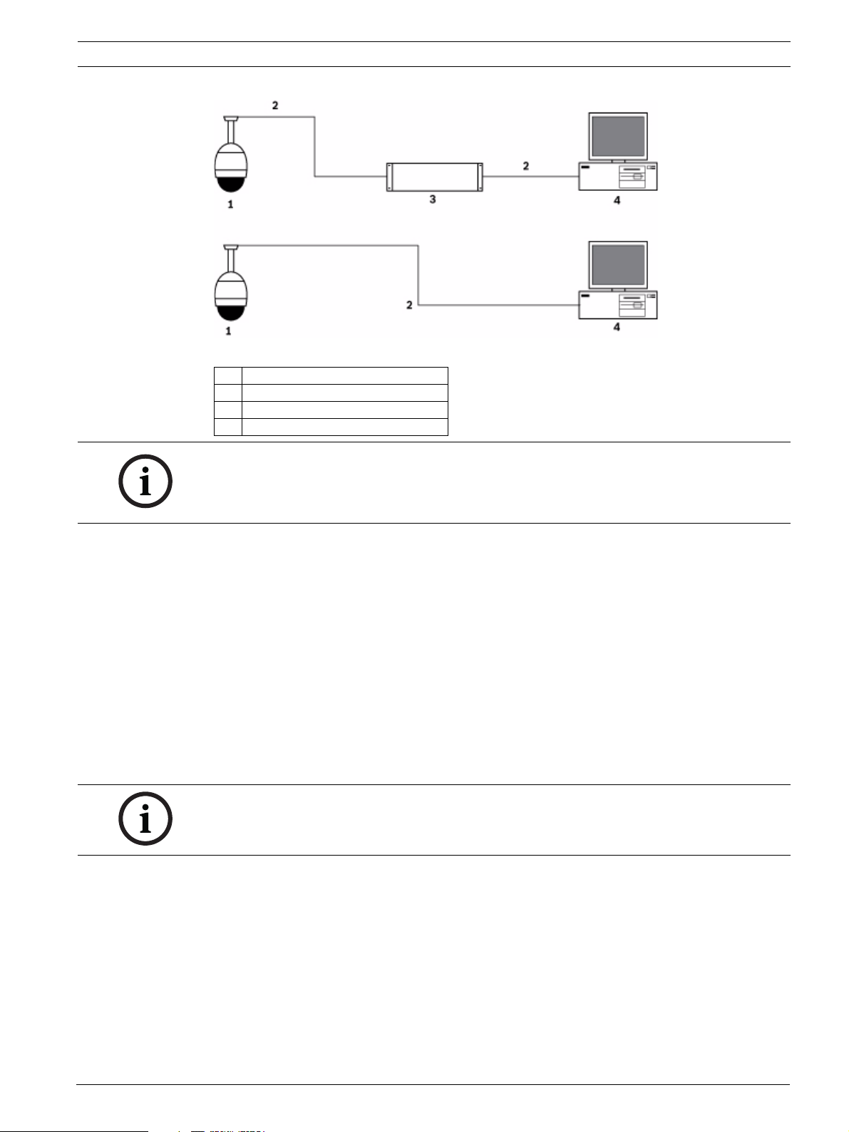
Figure 2.1 AutoDome 700 Series System Configuration
1 AutoDome 700 Series
2IP Connection
3 Network Switch
4Computer
NOTICE!
You can also use the Bosch Video Client utility to configure the network settings for an
AutoDome 700 Series camera. Go to www.boschsecurity.com to download the Configuration
Manager software and Operating Manual.
2.4 Configuring the AutoDome 700 Series Camera
To operate the camera in your network you must assign it a valid network IP address. The
default IP address is 192.168.0.1, but you may have to change this address if it conflicts with
another device on your network. Refer to Section 4.3 Basic Mode: Network, page 25 for more
information.
To properly configure the camera for your network, you need the following information:
– Unit IP address: An identifier for the camera on a TCP/IP network. For example,
140.10.2.110 is a valid syntax for an IP address.
– Subnet mask: A mask used to determine what subnet an IP address belongs to.
– Gateway IP address: A node on a network that serves as an entrance to another network.
– Port: An endpoint to a logical connection in TCP/IP and UDP networks. The port number
identifies the use of the port for use through a firewall connection.
NOTICE!
Ensure that the network parameters of your cameras are available before you begin
configuration.
The AutoDome 700 Series defaults are as follows:
– IP Address: 192.168.0.1
– Subnet Mask: 255.255.255.0
– Gateway IP Address: 0.0.0.0
The following sections provide instructions about installing the software necessary to view
images over an IP connection, configuring the IP network settings and accessing the
AutoDome 700 Series images from a Web browser.
Bosch Security Systems, Inc. User Manual F.01U.273.798 | 3.0 | 2012.08
10 en | Using the AutoDome 700 Series AutoDome 700 Series IP PTZ Camera
2.4.1 Changing the Network Settings
The AutoDome 700 Series has a default IP address of 192.168.0.1. To change the IP address
or any network settings, you can use the Configuration Manager software or the AutoDome
700 Series server.
NOTICE!
Contact your local network administrator for a valid IP address, Subnet Mask, and a Gateway
IP Address.
Using the Configuration Manager
Configuration Manager is an optional network utility provided on the Bosch Security Systems
Web site. Use the Configuration Manager Manual to make any configuration changes.
NOTICE!
Depending on the PC network security settings, the user may have to add the new IP address
to the browser’s trusted sites list for the IP AutoDome controls to operate.
Using the AutoDome 700 Series Web Server
To configure the camera using the AutoDome 700 Series server, do the following:
1. Set the IP address on the PC to 192.168.0.10 to ensure that the PC and the AutoDome
700 Series are on the same Subnet.
2. Launch Microsoft Internet Explorer and navigate to the following URL: http://192.168.0.1
The Web browser opens the Livepage for the AutoDome 700 Series; a security warning
message is displayed.
3. Check the Always Trust box, then click YES.
4. Click the Settings link, located at the top of the Livepage.
5. Click the Service Settings link, located in the left pane of the Settings window.
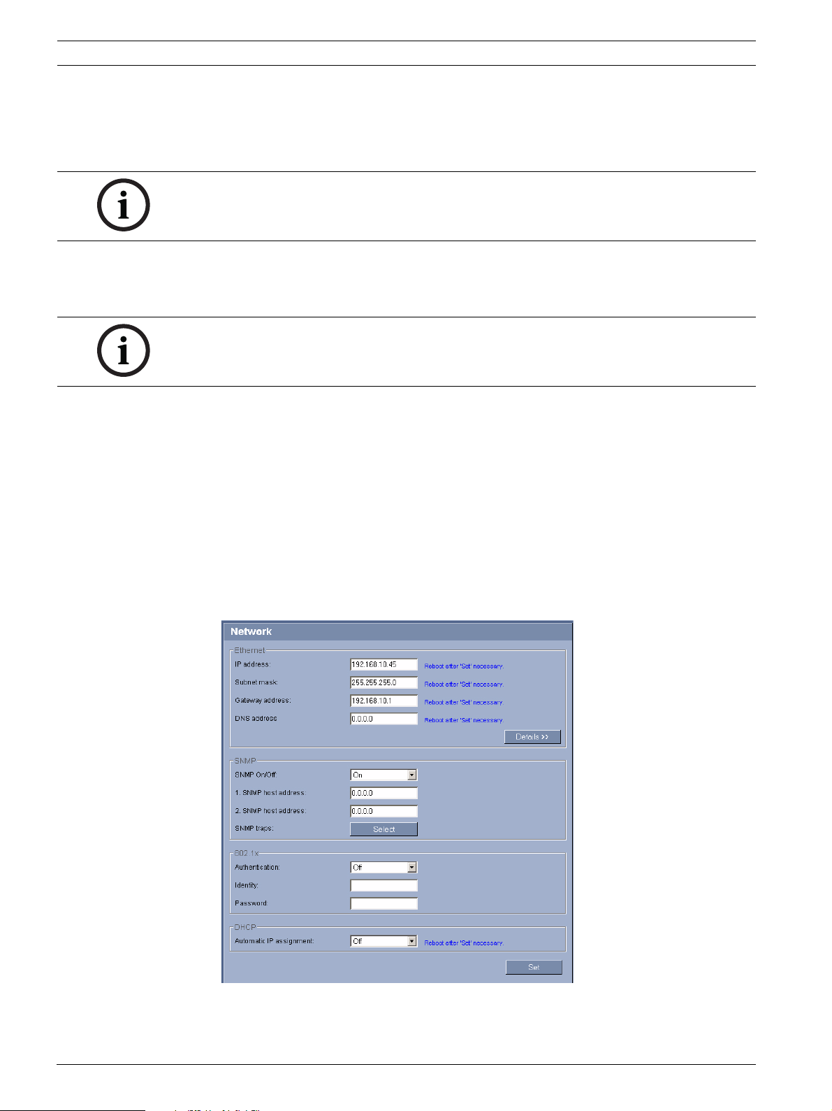
6. Click the Network link to open the Network Settings page.
Figure 2.2 Network Settings Page
7. Configure the settings on this page based on the addresses provided by your local
network administrator.
F.01U.273.798 | 3.0 | 2012.08 User Manual Bosch Security Systems, Inc.
AutoDome 700 Series IP PTZ Camera Using the AutoDome 700 Series | en 11
NOTICE!
Click the Help on this page? link if you need more information.
8. Click the Set button to save the settings.
9. Launch another instance of Microsoft Internet Explorer.
10. Type the original IP address followed by /reset (for example, http://192.168.0.1/reset) in
the address bar and click Go to restart the AutoDome 700 Series. Once you restart the
AutoDome 700 Series, use the new IP Address to access the Livepage.
11. Disconnect the AutoDome 700 Series Ethernet cable from the dedicated network switch
and reconnect the Ethernet cable to the local area network (LAN).
2.5 Configuring Intelligent Tracking
The AutoDome utilizes the built-in Intelligent Video Analytics (IVA) to continuously follow an
individual or object even if it passes behind a Privacy Mask or a stationary object. The
AutoDome uses objects detected by IVA in a stationary preset position to activate the
Intelligent Tracking feature. Intelligent Tracking controls the pan/tilt/zoom actions of the
camera to keep the selected object in the scene.
To activate the Intelligent Tracking feature, one of the following conditions must be met:
– The Silent IVA option must be selected in the VCA page on the Settings tab. Refer to
Section 4.40 VCA, page 50.
– IVA must be active for at least one preset scene in the VCA page on the Settings tab. If
IVA is configured for one scene, then all other scenes have Intelligent Tracking enabled by
default. If a scene, however, has Motion+ of IVA Flow activated then the Intelligent
Tracker is disabled for these scenes.
NOTICE!
The following actions occur if Intelligent Tracking is active:
– All other IVA objects are disabled in scenes with Intelligent Tracking.
– The camera automatically disables the display of compass headings. Refer to Page 41 for
details of the Compass feature.
2.5.1 Intelligent Tracking Operation
The Intelligent Tracking feature behaves in one of the following ways:
– Camera detects an object in motion and automatically tracks the object
User actions always take precedence over Intelligent Tracking. If the AutoDome is actively
tracking an object and a user takes control, the AutoDome will attempt to track the
object after a period of inactivity.
– An IVA alarm can trigger Intelligent Tracking to track a detected object
A rule that triggers an IVA event must be set. The following standard tasks can be set
Object in field, Crossing Line, Loitering, Condition change, Following route, Entering
field, and Leaving field. Refer to the IVA 5.51 Operation Guide for specific information.
– A user manually selects an object in the live image area to track
Intelligent Tracking allows a user to click a moving object in the live image display inside
the Livepage to identify an object to track.
– Use AUX Command 78 to activate/deactivate Intelligent Tracking
Use AUX ON 78 to enable the Intelligent Tracking Auto Mode. This command can be used
in conjunction with the rules engine.
Bosch Security Systems, Inc. User Manual F.01U.273.798 | 3.0 | 2012.08
12 en | Using the AutoDome 700 Series AutoDome 700 Series IP PTZ Camera
2.5.2 Guidelines for Implementing Intelligent Tracking
Factors such as the viewing angle and unwanted motion (from trees, for example) may
interfere with Intelligent Tracking operation. Use the following recommendations to ensure
smooth Intelligent Tracking operation:
– Mount/Mounting Surface Stability
– Mount the camera in the most stable position. Avoid locations affected by vibrations,
such as those caused by a roof-top air conditioner. These vibrations may cause
complications when the camera zooms-in on a target.
– Use the pendant arm mount, if possible. This mount option provides the most
stability for the camera.
– Use guy wires to protect against strong winds if using the parapet mount.
– Field of View
– Select a location and viewing angle that allows the flow of people to move across
the camera’s field of view.
– Avoid motion that moves directly towards the camera.
– Avoid locations that attract large numbers of people, such as retail stores or
intersections. Intelligent Tracking is optimized for scenes with very few moving
objects.
– Unwanted Motion
– Avoid neon lights, flashing lights, night time lights, and reflected light (from a
window or mirror, for example). The flickering of these lights can affect the
Intelligent Tracking operation.
– Avoid motion from moving leaves/branches that present a persistent fixed motion.
2.6 The Livepage
Once the connection is established, the Web browser displays the Livepage. It shows the live
video image on the right of the browser window. Depending on the configuration, various text
overlays may be visible on the live video image.
Other information may be shown next to live video image on the Livepage. The display
depends on the settings on the Livepage Configuration page (see the AutoDome 700 Series
online help).
Display Stamping
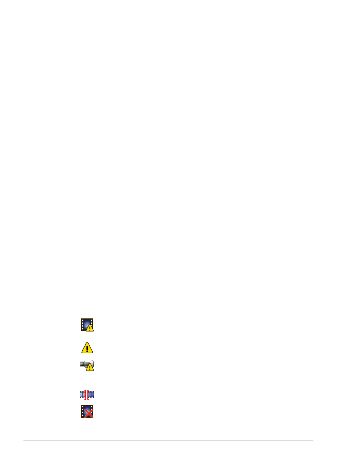
Various overlays or “stamps” in the video image provide important status information. The
overlays provide the following information:
Decoding error. The frame might show artefacts due to decoding errors. If subsequent
frames reference this corrupted frame, they might also show decoding errors as well
but won’t be marked with the “decoding error” icon.
Alarm flag set on media item
Communication error. Any kind of communication error is visualized by this icon.
Cause can be a connection failure to the storage medium, a protocol violation with a
sub component or simply a timeout. An automatic reconnection procedure is started
in the background in order to recover from this error.
Gap; no video recorded
Watermarking not valid
F.01U.273.798 | 3.0 | 2012.08 User Manual Bosch Security Systems, Inc.
AutoDome 700 Series IP PTZ Camera Using the AutoDome 700 Series | en 13
Watermarking flag set on media item
Motion flag set on media item
Discovery of storage not completed. If the information about recorded video is not
cached, a discovery procedure is started in order find all recorded video. During this
time, the “discovery” symbol is shown. While discovery is executed, gaps might be
shown in places which the discovery has not yet reached. The gap will automatically
be replaced by the true video, as soon as the correct information is available.
Maximum Number of Connections
If you do not connect, the unit may have reached its maximum number of connections.
Depending on the unit and network configuration, each AutoDome 700 Series can have up to
25 Web browser connections or up to 50 connections via the Bosch Video Management
System.
Protected AutoDome 700 Series
If the AutoDome 700 Series is password protected against unauthorized access, the Web
browser displays a corresponding message and prompts you to enter the password when you
attempt to access protected areas.
NOTICE!
An AutoDome 700 Series offers the option to limit the extent of access using various
authorization levels (see the AutoDome 700 Series online help).
1. Enter the user name and associated password in the corresponding text fields.
2. Click OK. If the password is entered correctly, the Web browser displays the page that
was called up.
Protected Network
If a RADIUS server is employed in the network for managing access rights (802.1x
authentication), the AutoDome 700 Series must be configured accordingly, otherwise no
communication is possible.
Image Selection
You can view the image of the camera in different displays.
Click one of the tabs Stream 1, Stream 2, or M-JPEG below the video image to toggle
between the different displays of the camera image.
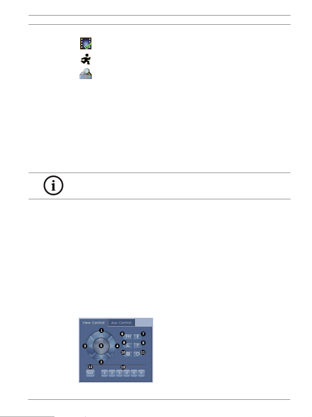
View Control
The View Control tab allows you to control camera functions (pan, tilt, zoom, focus, and iris),
navigate through on-screen menus and to view preset shots.
Bosch Security Systems, Inc. User Manual F.01U.273.798 | 3.0 | 2012.08
14 en | Using the AutoDome 700 Series AutoDome 700 Series IP PTZ Camera
Reference # Description Reference # Description
1 Tilts the camera up 8
2 Tilts the camera down 9
3 Pans the camera to the left 10
4 Pans the camera to the right 11
5 Pans and tilts the camera in all directions 12 Sets the pre-set shot for the
6
7
1. This function is also accessible by using the mouse scroll wheel while in the Live video frame.
2. This button is also used as the "Enter" button to select menu items from the AUX tab.
Zoom out
Zoom in
1
1
13 Moves the camera to pre-set shot
Focus far
Focus near
Iris close
Iris open
corresponding button 1, 2, 3, 4, 5 or 6
numbers 1, 2, 3, 4, 5, and 6
2
2
2
2
1. To control a peripheral, click the appropriate controls.
2. Move the mouse cursor over the video image. Additional options for controlling
peripherals are displayed with the mouse cursor.
3. To manually pan throughout the image area, move your cursor over any part of the live
video. The image area displays a directional arrow ( ), then click and hold the
right mouse key to pan the camera.
Digital I/O
The alarm icon is for information purposes and indicates the status of an alarm input: When
an alarm is triggered, the icon lights up blue. The device’s configuration determines whether
the alarm is displayed, as well as additional details (see the AutoDome 700 Series online
help).
Triggering Relay
You can switch connected units using the relays in the AutoDome 700 Series (for example
lights or door openers).
To activate this, click the icon for the relay next to the video image. The icon will be red
when the relay is activated.
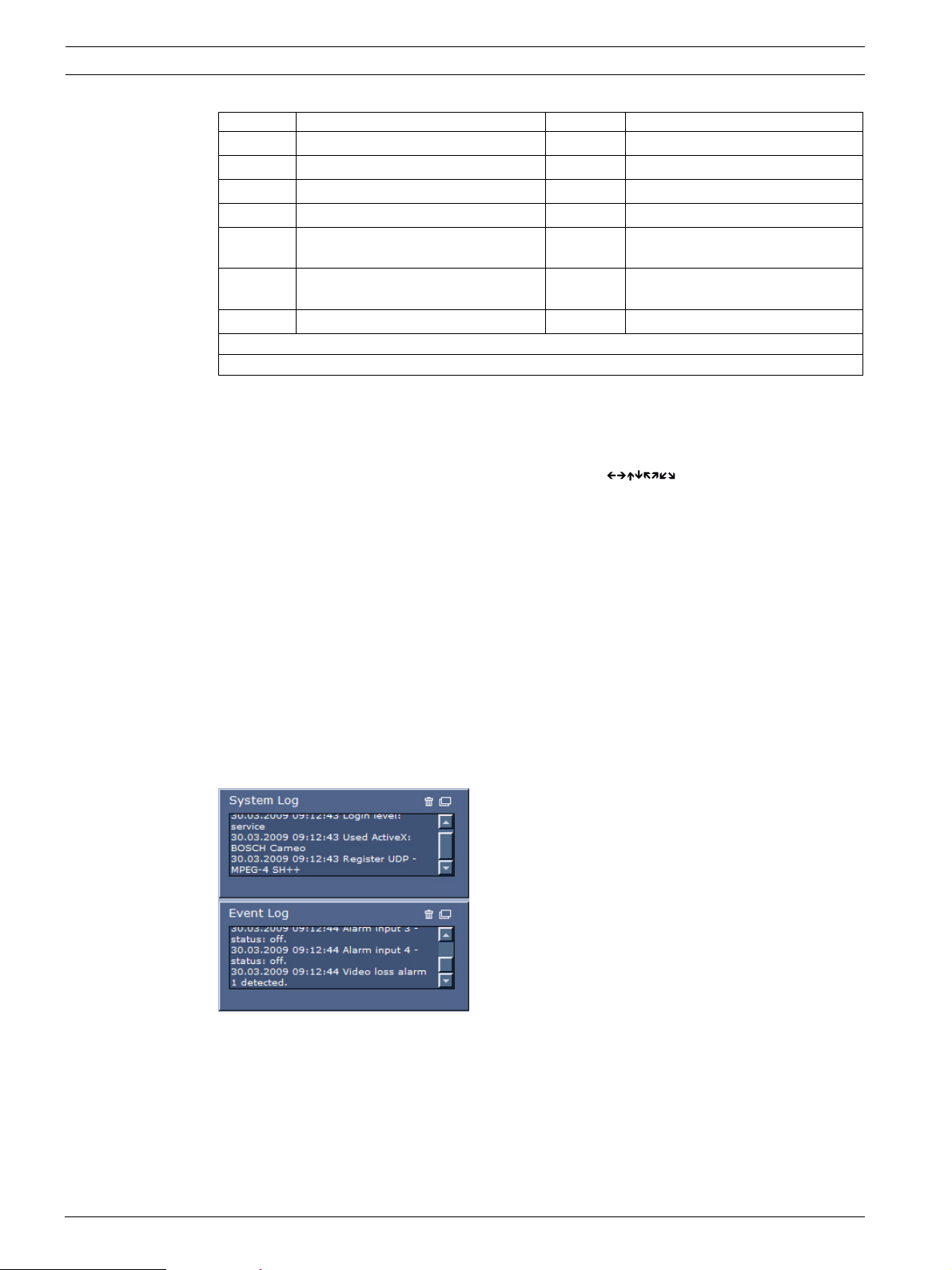
System Log / Event Log
The System Log field contains information about the operating status of the AutoDome 700
Series and the connection. You can save these messages automatically in a file (see the
AutoDome online help).
Events such as the triggering or end of alarms are shown in the Event Log field. You can save
these messages automatically in a file (see the AutoDome online help).
1. If you want to delete the entries, click the delete icon in the top right-hand corner of the
relevant field.
F.01U.273.798 | 3.0 | 2012.08 User Manual Bosch Security Systems, Inc.
AutoDome 700 Series IP PTZ Camera Using the AutoDome 700 Series | en 15
2. If you want to view a detailed log, click the icon in the top right-hand corner of the
relevant field. A new window will open.
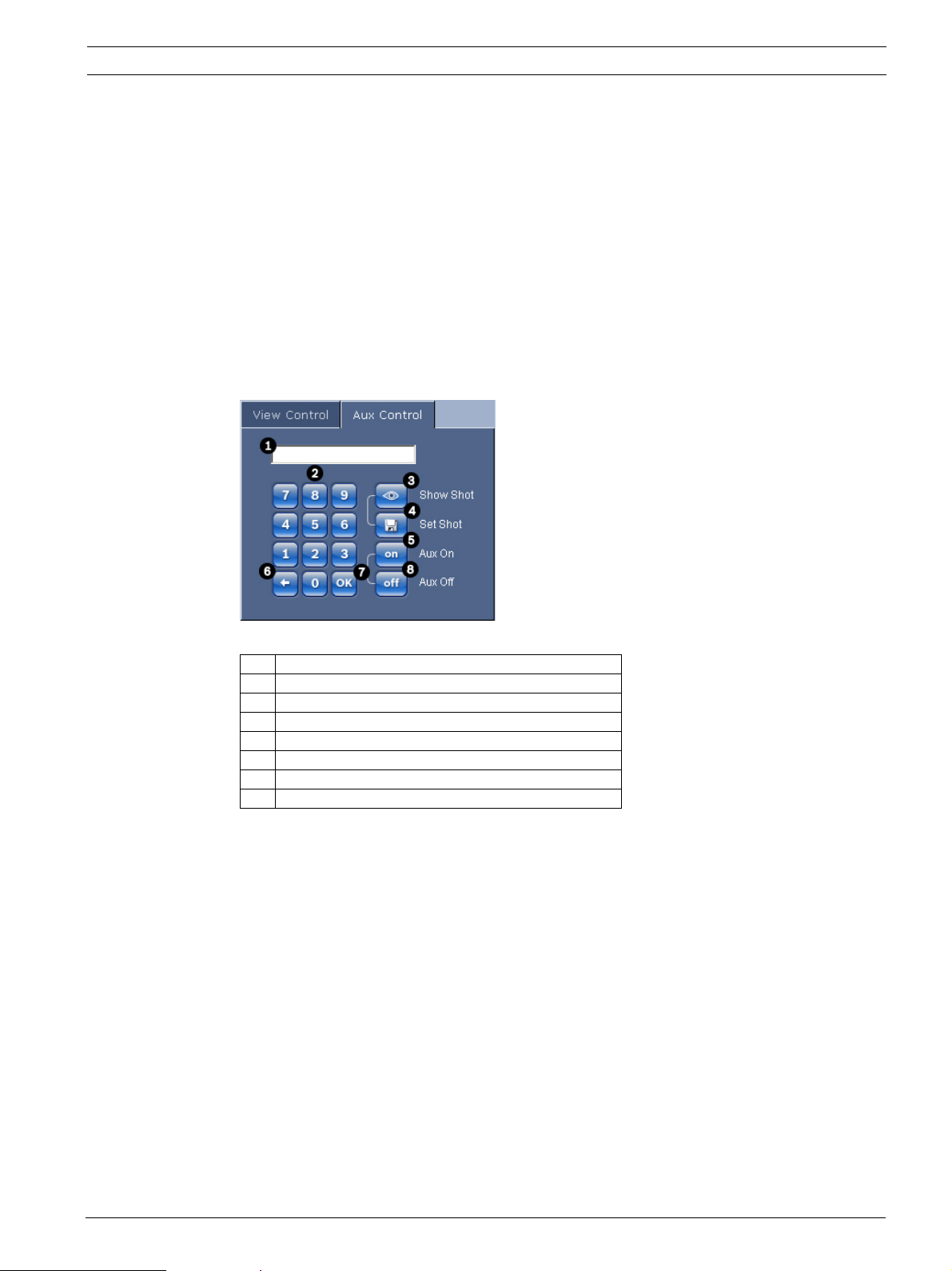
2.6.1 Entering a Keyboard Control Command
The Aux Control tab is used to enter keyboard control commands. These commands are
composed of a command number plus the appropriate function key (Show Shot, Set Shot Aux
On or Aux Off). A valid combination either issues a command to the camera or displays an onscreen menu.
Aux Control Tab
The Aux Control tab is used to enter pre-programmed keyboard control commands.
See Section 6 User Command Table, page 71, for a list of all commands.
To access the Aux Control tab, navigate to the Livepage and click the Aux Control tab (see
Figure 2.3 below).
Figure 2.3 Aux Control Tab
1 Command number field
2 Keypad (numbers 0-9)
3 Show a preset shot
4 Set a preset shot
5 Initiates a command
6 Deletes a number in the Command Number field
7 Used to select a menu item
8 Stops a command
To Enter a Keyboard Control Command:
1. Place the cursor in the Command Number field.
2. Click the desired command number via the on-screen keypad.
3. Click either the Aux On or the Aux Off button to initiate or stop the command.
4. If the command initiates a menu, use the Up/Down arrows on the View Control to
navigate the menu. Click the Focus or Iris button to select a menu item.
To Set a Preset Shot:
Preset shots (or scenes) are camera positions that are saved in memory for future use.
1. Move your cursor over the live image and wait for the area to display a directional arrow.
2. Click and hold a mouse button to pan to the desired position you want to save.
3. Click any number combination from 1-99 from the on-screen keypad to identify the scene
number.
4. Click the Set Shot button. The image area displays a message that indicates which shot
number was saved.
To View a Preset Shot:
1. Click the number of the scene you want to view using the on-screen keypad.
Bosch Security Systems, Inc. User Manual F.01U.273.798 | 3.0 | 2012.08
16 en | Using the AutoDome 700 Series AutoDome 700 Series IP PTZ Camera
2. Click the Show Shot button.
NOTICE!
For more information about the AutoDome 700 Series settings and controls, click the Help on
this page? link to open the AutoDome 700 Series online help.
2.6.2 Using Intelligent Tracking
Intelligent Tracking continuously follows an individual or an object. Intelligent Tracking
operates by recognizing an object in motion and zooms-in to approximately 50% of the field of
view for an average target height of six feet. Refer to Section 2.5 Configuring Intelligent
Tracking, page 11, for details about activating the Intelligent Tracking feature.
Note: If you do not see these controls on the Livepage, ensure that the Enable AutoTrack
option is selected on the Livepage Functions page in the Settings tab. Refer to
Section 4.15 Livepage Functions, page 31.
Use the following options to control Intelligent Tracking:
– Off: Disables Intelligent Tracking.
– Auto: Enables Intelligent Tracking. Constantly monitors for and actively tracks motion.
– Click: Allows a user to click on a moving target in the live video image to enable the VG5
700 AutoDome to track the movement of the selected target.
Note: This feature is available only from the Livepage. This feature is not available from
the Bosch Video Controller version 1.3.812. Support for the Click feature is planned for
the BVC 1.4 release.
NOTICE!
When Intelligent Tracking is activated, the AutoDome disables the display of the compass
heading. Once Intelligent Tracking is set to Off, the AutoDome resumes display of the
compass heading. Refer to Page 41 for details of the Compass feature.
If the Intelligent Tracking feature is set to Auto or Click, the live video image displays an eye
icon in a color that conveys the state of the Intelligent Tracking:
– SEEK state: steady white
Intelligent Tracking is actively seeking a target to follow.
– IDLE state: alternating black and white, slow cycle
Intelligent Tracking lost the selected target and will wait for the target to reappear using
the last known trajectory. During the IDLE state the camera will not seek other objects in
motion.
– ACTIVE state: alternating black and white, fast cycle
Intelligent Tracking is actively tracking a target.
– PASSIVE state: steady black
Intelligent Tracking attempts to passively track a target while a user has camera control.
Several reasons may cause the Intelligent Tracking to stop tracking a target:
– The target has stopped moving while being followed by Intelligent Tracking.
– The target has moved behind a static object in the scene.
In these instances Intelligent Tracking switches to the IDLE mode (pink eye icon) and waits
for the target to reappear in the scene. The camera will restart tracking if a target starts
moving in the same area where the initial target stopped moving or if the camera detects an
object moving along the last known trajectory.
If the Show VCA metadata option is selected (in the Settings page - > Livepage Settings) the
live view will show the following metadata objects in the Livepage view:
– Objects in motion are initially identified in the video by a yellow outline.
F.01U.273.798 | 3.0 | 2012.08 User Manual Bosch Security Systems, Inc.
AutoDome 700 Series IP PTZ Camera Using the AutoDome 700 Series | en 17
– Actively tracked object in motion are identified in the video by a blue outline.
– When an object in motion is lost, a blue diamond appears designating the area where the
target was lost.
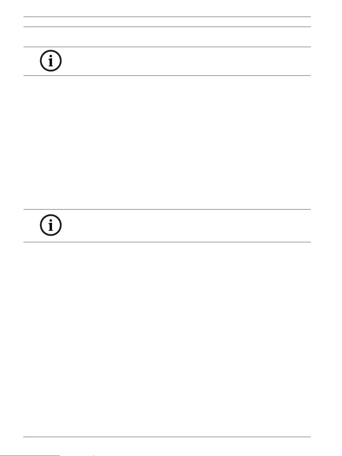
2.6.3 Using Special Functions
The AutoDome offers several special command buttons on the Livepage.
Scan 360
Click this button to start a continuous 360° pan. To stop the continuos pan, click a directional
control in the View Control tab.
Autopan
Click this button to pan the AutoDome between user-defined limits. To set the left and right
pan limits, refer to Section 4.24 PTZ Settings, page 40, so set the Autopan limits. To stop the
continuos pan, click a directional control in the View Control tab.
Tour A / Tour B
Click one of these buttons to start a recorded (guard) tour. A Recorded Tour saves all manual
camera movements made during the recording, including its rate of pan, tilt and zoom speeds
and other lens setting changes. Refer to Section 4.24 PTZ Settings, page 40, to program a
recorded tour. To stop a tour, click a directional control in the View Control tab.
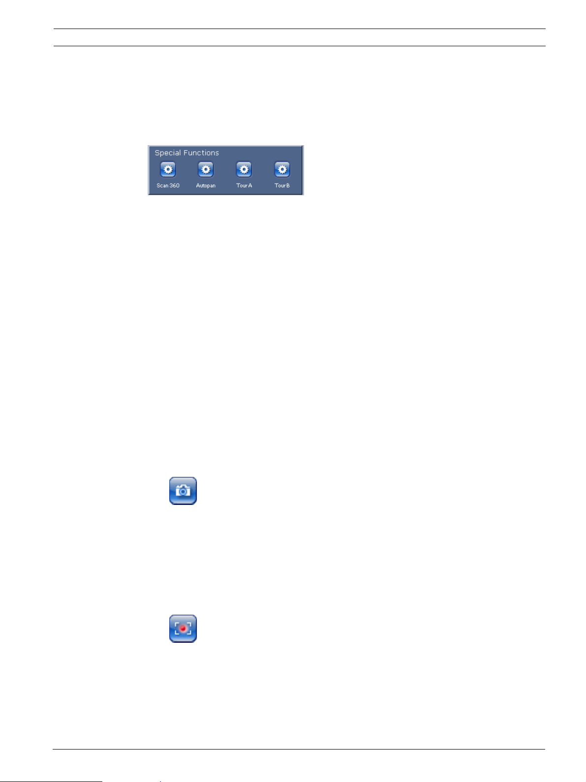
2.7 Saving Snapshots
You can save individual images from the video sequence currently shown on the Livepage in
JPEG format on your computer's hard drive. The icon for recording single images is only
visible if the unit is configured to enable this process.
Click the icon. The storage location depends on the configuration of the AutoDome 700
Series.
2.8 Recording Video Sequences
You can save sections of the video sequence currently shown on the Livepage on your
computer's hard drive. The icon for recording video sequences is only visible if the unit is
configured to enable this process.
1. Click the icon to start recording. The storage location depends on the configuration of
the AutoDome 700 Series. A red dot in the icon indicates that recording is in progress.
2. Click the icon again to stop recording.
3. To change the storage location for the recorded video, navigate to the Livepage settings
on the Settings page.
Image Resolution
Sequences are saved at the resolution that has been preset in the configuration for the
encoder (see Section 4.3 Basic Mode: Network, page 25).
Bosch Security Systems, Inc. User Manual F.01U.273.798 | 3.0 | 2012.08

18 en | Using the AutoDome 700 Series AutoDome 700 Series IP PTZ Camera
2.9 Processor Load
If the AutoDome 700 Series is accessed via the Web browser, you will see the processor load
indicator in the top left of the window next to the manufacturer's logo.
You can obtain additional information to help when you troubleshoot or fine-tune the unit. The
values indicate the proportions of the individual functions on the encoder load, shown as
percentages.
Move the cursor over the graphic indicator. Some additional numerical values are also
displayed.
F.01U.273.798 | 3.0 | 2012.08 User Manual Bosch Security Systems, Inc.
AutoDome 700 Series IP PTZ Camera Using the AutoDome 700 Series | en 19
2.10 Recordings page
Click Recordings to access the Recordings page from the Livepage or Settings page (the
Recordings link is only visible if a storage medium has been selected).
Selecting Recordings
All saved sequences are displayed in a list. A track number is assigned to each sequence. Start
time and stop time, recording duration, number of alarms, and recording type are displayed.
To play back recorded video sequences:
1. Select Recording 1 or 2 in the drop-down menu. (The contents for 1 and 2 are identical,
only the quality and location may be different.)
2. Use the arrow buttons to browse the list.
3. Click a track. The playback for the selected sequence starts.
Export to FTP
Click Export to FTP to send the current track to the FTP server. If required, change the times
within the selected range.
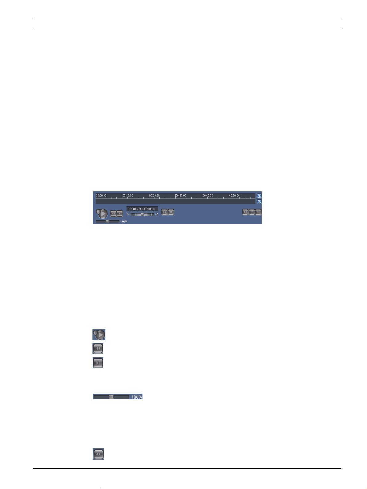
2.10.1 Controlling playback
A time bar below the video image allows quick orientation. The time interval associated with
the sequence is displayed in the bar in gray. A green arrow above the bar indicates the
position of the image currently being played back within the sequence.
The time bar offers various options for navigation in and between sequences.
– Change the time interval displayed by clicking the plus or minus icons. The display can
span a range from two months to a few seconds.
– If required, drag the green arrow to the point in time at which the playback should begin.
– Red bars indicate the points in time where alarms were triggered. Drag the green arrow
to navigate to these points quickly.
Control playback by means of the buttons below the video image. The buttons have the
following functions:
Start/Pause playback
Jump to start of active sequence or to previous sequence
Jump to start of the next video sequence in the list
Slide control
Continuously select playback speed by means of the speed regulator:
Bookmarks
In addition, set markers in the sequences, so-called bookmarks, and jump directly to these.
These bookmarks are indicated as small yellow arrows above the time interval. Use the
bookmarks as follows:
Jump to the previous bookmark
Bosch Security Systems, Inc. User Manual F.01U.273.798 | 3.0 | 2012.08

20 en | Using the AutoDome 700 Series AutoDome 700 Series IP PTZ Camera
Set bookmark
Jump to the following bookmark
Bookmarks are only valid while in the Recordings page; they are not saved with the
sequences. All bookmarks are deleted when leaving the page.
F.01U.273.798 | 3.0 | 2012.08 User Manual Bosch Security Systems, Inc.
AutoDome 700 Series IP PTZ Camera VG5 Audio Connections | en 21
3 VG5 Audio Connections
The audio version of the AutoDome 700 Series has one audio input for line signals. The audio
signals are transmitted one-way and in-sync with the video signals. As a result, a door
intercom system can be connected at the camera location.
NOTICE!
The line ports of the intercom should be used for transmitting audio signals on the intercom
systems.
3.1 Audio Line Input Specifications
The following Line In specifications should be complied with in all cases:
– 5.5 Vpp max. Input voltage Impedance 9 Kohm, typical
– Sampling rate 8 KHz, 16 Bit, mono
NOTICE!
There is an internal gain level adjustment in case the signal level is too low.
3.1.1 Wire Specifications
Long distances are more susceptible to introducing noise into the signal.
Wire Type: Coax wire, AWG is dependant on the connector style selected
Maximum Distance: Depends on the signal level
3.1.2 Connections
The Audio Input must be connected to the Biphase Input as follows:
1. Remove the 110 Ω Biphase termination resistor.
2. Connect an audio source with line level to the Biphase input of the VG5 as shown in the
chart below:
Contact Description
Biphase + Audio In
Biphase - Ground
3.1.3 Activating Audio Reception
To configure audio via the Web browser, do the following:
1. Open the AutoDome 700 Series Livepage, then click the Settings tab.
2. Click the Camera Settings link from the left pane, then click Audio. The AutoDome 700
Series displays the Audio settings.
3. Select the Audio protocol to activate audio over IP.
NOTICE!
The audio signal is sent in a separate data stream parallel to the video data, and so increases
the network load. The audio data is encoded according to G.711 or L16 and requires an
additional bandwidth of approximately 80 Kbit/s for each connection.
3.1.4 Enabling Audio Transmission
To transmit audio via the IP connection, do the following:
1. Open the AutoDome 700 Series Livepage, then click the Settings tab.
2. Click Web Interface from the left pane, then click Livepage Functions. The AutoDome 700
Series displays the Livepage Function screen.
3. Click the Transmit Audio radio button to enable for audio.
Bosch Security Systems, Inc. User Manual F.01U.273.798 | 3.0 | 2012.08

22 en | VG5 Audio Connections AutoDome 700 Series IP PTZ Camera
3.1.5 Configuring Gain (optional)
Input gain control is supported over a range of -34dB to +12dB. Click the Audio link in the
Settings page. The page displays the current video image in the small window next to the slide
controls to help verify the audio source and improve the Peak levels. Set the gain of the audio
signals to suit your specific requirements. Changes are effective immediately. The current
level is displayed next to the slide control to help do this. Make sure that the display does not
go beyond the green zone during modulation.
F.01U.273.798 | 3.0 | 2012.08 User Manual Bosch Security Systems, Inc.
AutoDome 700 Series IP PTZ Camera Configuring the AutoDome 700 Series | en 23
4 Configuring the AutoDome 700 Series
The SETTINGS page provides access to the configuration menu, which contains all the unit's
parameters arranged in groups. You can view the current settings by opening one of the
configuration screens. You can change the settings by entering new values or by selecting a
predefined value from a list field.
There are two options for configuring the unit or checking the current settings:
– Basic mode
– Advanced mode
In Basic Mode the most important parameters are arranged in seven groups. This allows you
to change the basic settings with just a few entries and then put the device into operation.
Advanced Mode is recommended for expert users or system support personnel. You can
access all unit parameters in this mode. Settings that affect the fundamental functionality of
the unit (such as firmware updates) can only be altered in the advanced mode.
All parameter groups are described in this chapter in the order in which they are listed in the
configuration menu, from the top of the screen to the bottom.
CAUTION!
The settings in the advanced mode should only be processed or modified by expert users or
system support personnel.
All settings are backed up in the AutoDome 700 Series memory so they are not lost even if the
power fails.
Starting Configuration
Click the SETTINGS link in the upper section of the window. The Web browser opens a
new page with the configuration menu.
Navigation
1. Click one of the menu items in the left window margin. The corresponding submenu is
displayed.
2. Click one of the entries in the submenu. The Web browser opens the corresponding
page.
Making Changes
Each configuration screen shows the current settings. You can change the settings by entering
new values or by selecting a predefined value from a list field.
Not every page has a Set button. Changes to pages without a Set button are set immediately.
If a page does show a Set button, you must click the Set button for a change to take effect.
CAUTION!
Save each change with the associated Set button.
Clicking the Set button saves the settings only in the current field. Changes in any other fields
are ignored.
4.1 Basic Mode: Device Access
Device name
You can give the AutoDome 700 Series a name to make it easier to identify. The name makes
the task of administering multiple units in larger video monitoring systems easier, for example
using the Bosch Video Management System programs.
The device name is used for the remote identification of a unit, in the event of an alarm for
example. For this reason, enter a name that makes it as easy as possible to quickly identify the
location.
Bosch Security Systems, Inc. User Manual F.01U.273.798 | 3.0 | 2012.08
24 en | Configuring the AutoDome 700 Series AutoDome 700 Series IP PTZ Camera
CAUTION!
Do not use any special characters, for example &, in the name.
Special characters are not supported by the system's internal recording management and may
therefore result in the Player or Archive Player being unable to play back the recording.
Password
An AutoDome 700 Series is generally protected by a password to prevent unauthorized access
to the unit. You can use different authorization levels to limit access.
The AutoDome 700 Series operates with three authorization levels: service, user and live.
The highest authorization level is service. After entering the correct password, you can access
all the functions of the AutoDome 700 Series and change all configuration settings.
With the user authorization level, you can operate the unit and also control cameras, for
example, but you cannot change the configuration.
The lowest authorization level is live. It can only be used to view the live video image and
switch between the different live image displays.
You can define and change a password for each authorization level if you are logged in as
service or if the unit is not password protected.
Enter the password for the appropriate authorization level here.
NOTICE!
Proper password protection is only guaranteed when all higher authorization levels are also
protected with a password. If a live password is assigned, for example, a service and a user
password must also be set. When assigning passwords, you should therefore always start
from the highest authorization level, service, and use different passwords.
Confirm password
In each case, enter the new password a second time to eliminate typing mistakes.
NOTICE!
A new password is only saved when you click the Set button. You should therefore click the
Set button immediately after entering and confirming a password.
4.2 Basic Mode: Date/Time
Device date/Device time/Device time zone
If there are multiple devices operating in your system or network, it is important to
synchronize their internal clocks. For example, it is only possible to identify and correctly
evaluate simultaneous recordings when all units are operating on the same time. If necessary,
you can synchronize the unit with your computer's system settings.
Click the Sync to PC button to copy your computer's system time to the AutoDome 700
Series.
Time server IP address
The AutoDome 700 Series can receive the time signal from a time server using various time
server protocols, and then use it to set the internal clock. The unit polls the time signal
automatically once every minute.
Enter the IP address of a time server here.
Time server type
Select the protocol that is supported by the selected time server. Preferably, you should
select the SNTP server as the protocol. This supports a high level of accuracy and is required
for special applications and subsequent function extensions.
F.01U.273.798 | 3.0 | 2012.08 User Manual Bosch Security Systems, Inc.
AutoDome 700 Series IP PTZ Camera Configuring the AutoDome 700 Series | en 25
Select Time server for a time server that works with the protocol RFC 868.
4.3 Basic Mode: Network
The settings on this page are used to integrate the AutoDome 700 Series into an existing
network.
Some changes only take effect after the unit is rebooted. In this case, the Set button changes
to Set and Reboot.
1. Make the desired changes.
2. Click the Set and Reboot button. The AutoDome 700 Series is rebooted and the changed
settings are activated.
CAUTION!
If you change the IP address, subnet mask or gateway address, the AutoDome 700 Series is
only available under the new addresses after the reboot.
DHCP
If a DHCP server is employed in the network for the dynamic assignment of IP addresses, you
can activate acceptance of IP addresses automatically assigned to the AutoDome 700 Series.
Certain applications (VIDOS, Bosch Video Management System, Archive Player, Configuration
Manager) use the IP address for the unique assignment of the unit. If you use these
applications, the DHCP server must support the fixed assignment between IP address and
MAC address, and must be appropriately set up so that, once an IP address is assigned, it is
retained each time the system is rebooted.
IP address
Enter the desired IP address for the AutoDome 700 Series in this field. The IP address must
be valid for the network.
Subnet mask
Enter the appropriate subnet mask for the selected IP address here.
Gateway address
If you want the unit to establish a connection to a remote location in a different subnet, enter
the IP address of the gateway here. Otherwise leave the box blank (0.0.0.0).
4.4 Basic Mode: Encoder
Non-recording profile
You can select a profile for encoding the video signal.
You can use this to adapt the video data transmission to the operating environment (for
example network structure, bandwidth, data load).
Pre-programmed profiles are available, each giving priority to different perspectives. When
selecting a profile, details are displayed in the list field.
– High resolution 1
Target bit rate: 2000 kbps
Maximum bit rate: 4000 kbps
Encoding interval: 30.00 ips
– High resolution 2
Target bit rate: 1500 kbps
Maximum bit rate: 3000 kbps
Encoding interval: 30.00 ips
Bosch Security Systems, Inc. User Manual F.01U.273.798 | 3.0 | 2012.08
 Loading...