

Page 1
Quick Start Guide
560/583 DDC
Please refer to the included Hardware User’s Guide and BACview Installation and
Operation Manual for more detailed information on setting up and using the controllers.
8733914716(2014/02)
Page 2

2 |
Quick Start Guide
8733914716 DDC (2014/02) Subject to change without prior notice Quick Start Guide
Page 3

Quick Start Guide
CONTENTS
Quick Start Guide – Hardware Setup .................4
Controller Features .............................4
Getting Started ...................................5
Jumper Settings. . . . . . . . . . . . . . . . . . . . . . . . . . . . . . . . . . 5
DIP Switch Settings ...............................6
Rotary Dial Settings ...............................7
Power Up .......................................7
Quick Start Guide – Software Setup ..................8
Software Conguration Tools ....................8
Handheld BACview Module Features ..............8
Virtual BACview Module Features .................9
Getting Connected ...............................10
Conguring Application Parameters using BACview ...11
Modifying Parameter Values Using BACview .........11
Customizing Program Features Using BACview ......12
Useful Shortcuts for Tweaking Program Features
Using BACview ...............................12
Congurable I/O Port Assignments (SW 7.03.06) ......13
Wiring Diagram .................................14
Typical FHP560 Wiring Diagram ...................14
Table of Contents
| 3
Quick Start Guide Subject to change without prior notice 8733914716 DDC (2014/02)
Page 4
4 |
Hardware Setup
Quick Start Guide – Hardware Setup
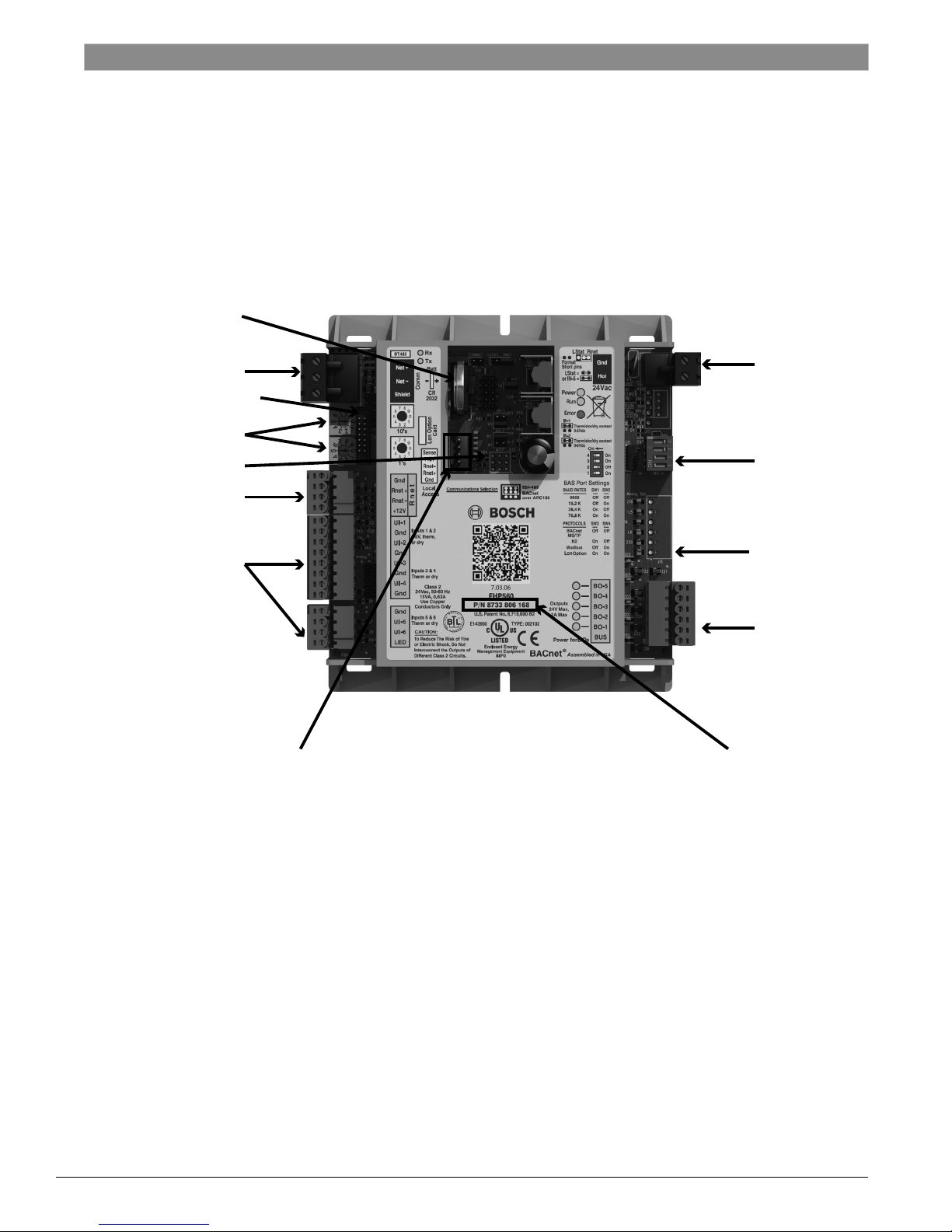
Controller Features
Battery
Quick Start Guide
Network
LON Connector
Rotary Switch
Jumper Bank
RNET
Connector
Universal
Inputs
IN-1 to IN-6
Local Access Port
(see page 10)
24VAC
DIP Switch
Bank
Analog
Outputs
(583 only)
Digital
Outputs
Part Number
8733914716 DDC (2014/02) Subject to change without prior notice Quick Start Guide
©Copyright 2014 Bosch, Inc All rights reserved
FHP 560 Controller
Page 5
Quick Start Guide
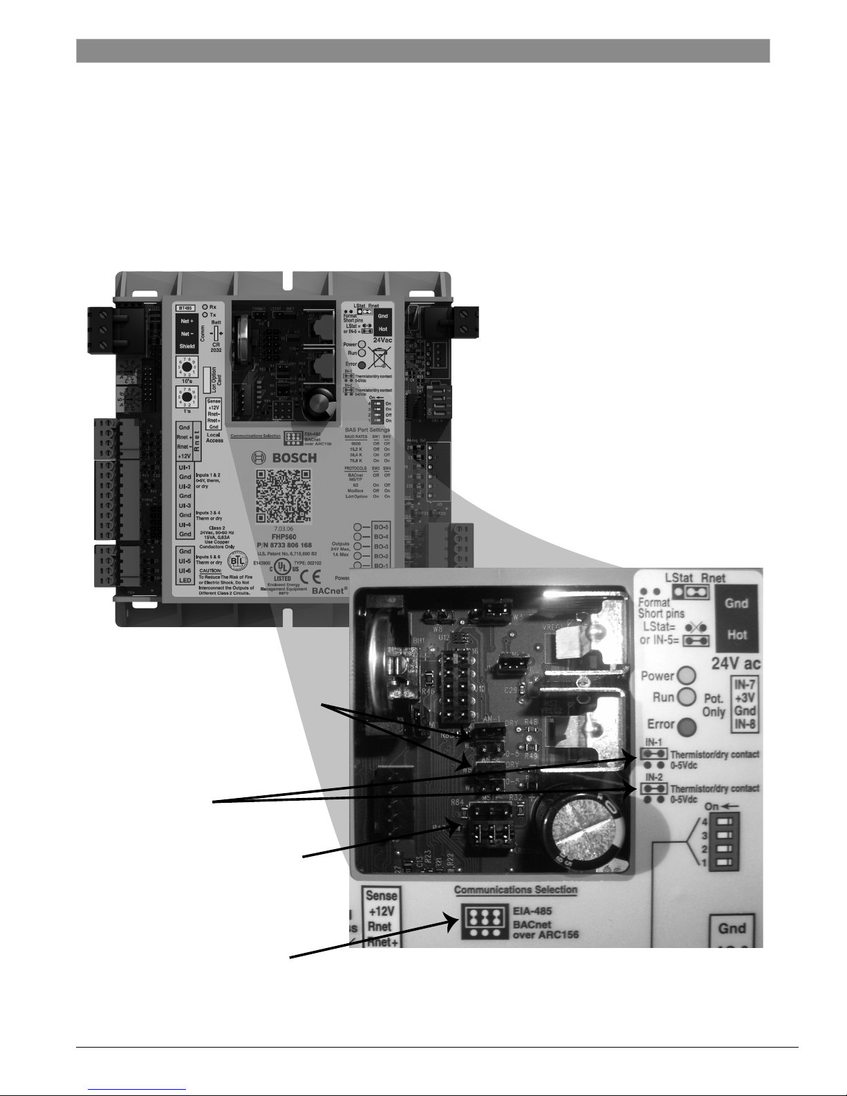
Input Selection Jumpers for IN-1 & IN-2
(e.g. for a 0-5V CO2 Sensor
connected to IN-1, the jumper
should be set in bottom position)
IN-1 & IN-2 Jumper
Settings Label
Communications Selection Jumper
(i.e. jumper in bottom position for
BACnet over ARC156, or, jumper in top
position for EIA-485 using BACnet over
MS/TP, LON, Modbus, or N2 protocols)
Communications Selection label
Getting Started
| 5
GETTING STARTED
Perform a quick visual inspection to ensure the
controller has no external damage and all connectors
are intact. Ensure wiring is per desired application
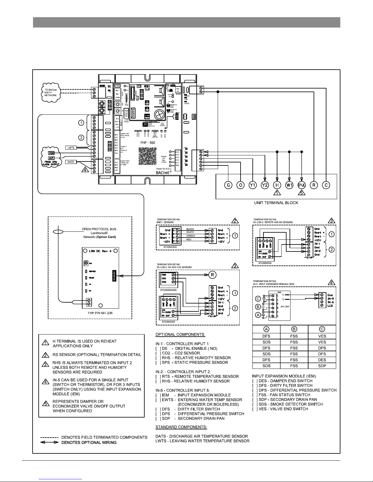
(see sample FHP 560 wiring diagram on page 14).
Refer to I/O port conguration (page 13) for further
details on wiring inputs and outputs.
JUMPER SETTINGS
Verify that hardware conguration for jumpers
match corresponding Heat Pump system
application. If the controller is networked, ensure
communications jumper is set to EIA-485, unless
the network protocol is BACnet over ARC156.
Quick Start Guide Subject to change without prior notice 8733914716 DDC (2014/02)
In the above diagram, IN-1 and IN-2 are set to Thermistor/Dry
Contact, and Communications is set to BACnet over ARC156.
Page 6
6 |
DIP Switch Settings
DIP SWITCH SETTINGS
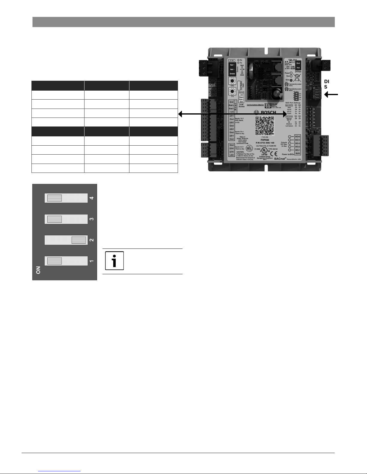
Verify that hardware conguration for DIP switches
match corresponding network application per the
BAS Port Settings.
BAUD RATES SW1 SW2
9600 Off Off
19.2K Off On
38.4K On Off
76.8K On On
PROTOCOLS SW3 SW4
BACnet® MS/TP Off Off
N2 On Off
Modbus Off On
LON Option On On
Quick Start Guide
DIP
Switch
Sample DIP switch settings for a
LON Talk Application.
The LonTalk® card
must be installed
8733914716 DDC (2014/02) Subject to change without prior notice Quick Start Guide
Page 7
Quick Start Guide
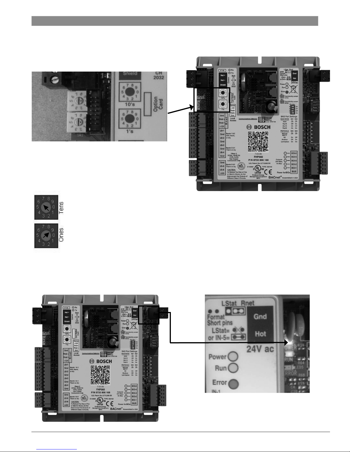
ROTARY DIAL SETTINGS
Verify hardware conguration for rotary dials matches
corresponding application.
The rotary dials provide the controller address for
identication over a network.
The top dial represents the tens digit of the address,
and the bottom dial represents the ones digit for the
address. See example below:
Rotary Dial Settings
| 7
In the example to the left,
the rotary dial is set to 69.
POWER UP
Apply power to the unit and verify via the power LED
that the controller is receiving 24VAC.
Quick Start Guide Subject to change without prior notice 8733914716 DDC (2014/02)
Page 8
Software Setup
8 |
Quick Start Guide – Software Setup
Software Conguration Tools
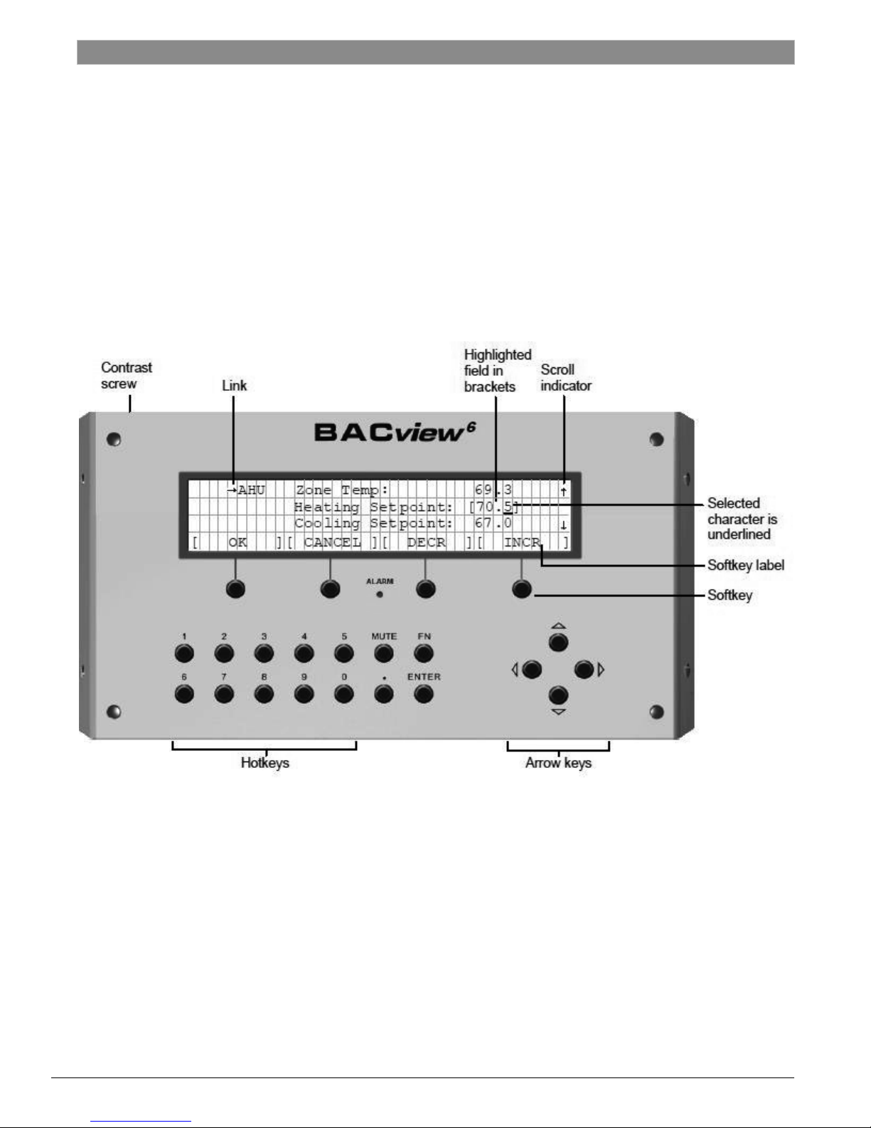
Handheld BACview Module Features
Quick Start Guide
• Hot-keys: used for entering number values.
• Arrow keys: used for navigating the various
BACview screens.
• Soft- keys: four (4) buttons used to access
corresponding Soft-key Labels directly above them.
8733914716 DDC (2014/02) Subject to change without prior notice Quick Start Guide
• Link: an arrow next to a menu item implies
additional screen(s) can be accessed through
that menu. To access a screen navigate to the
menu item and hit the ENTER button. (Note:
selected elds have a bracket [...] around them).
• Contrast screw: used to adjust screen contrast.
Page 9
Quick Start Guide
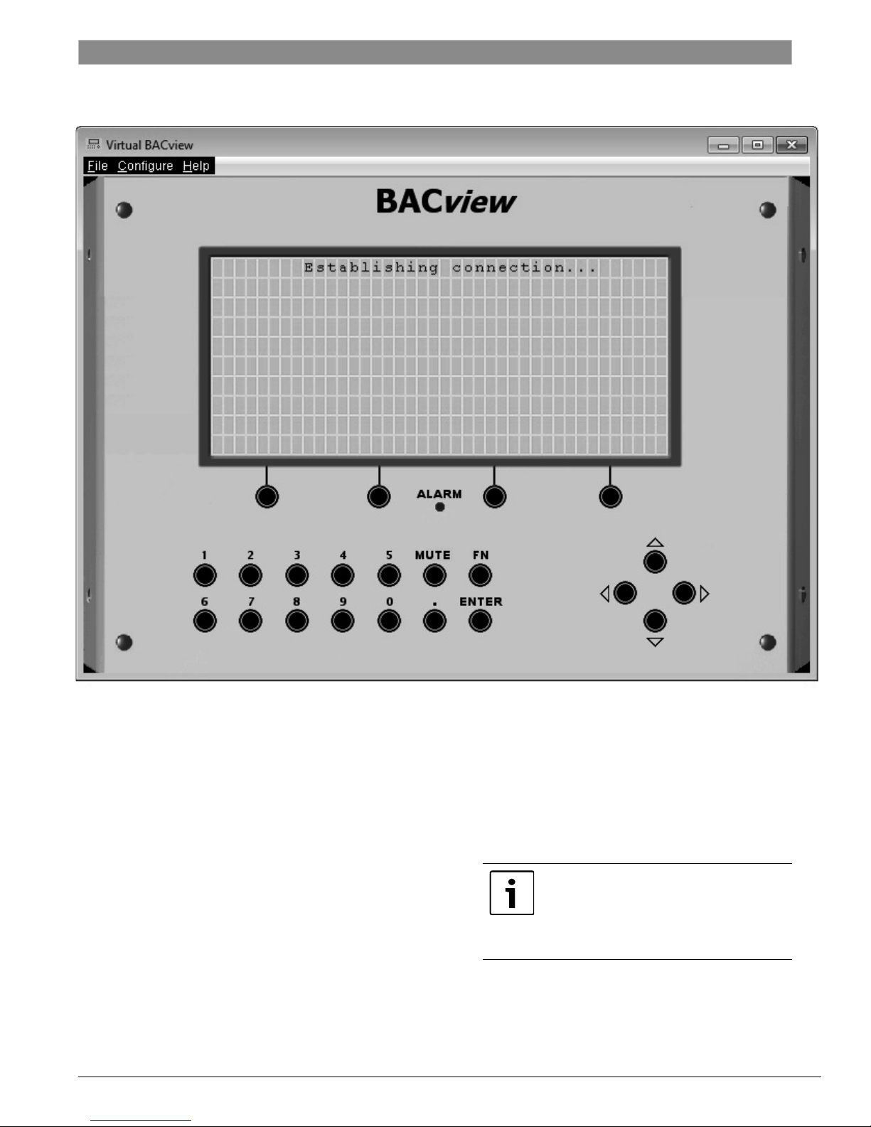
Virtual BACview Features
Virtual BACview Features
| 9
Installation
• Download and install driver for USB cable (cable p/n
641-261 purchase required) from FHP website
(http://fhp-mfg.com/?p=controls_support).
• Verify device is installed in Device Manager and take
note of COM port.
• Download and install Virtual BACview from FHP
website (http://fhp-mfg.com/?p=controls_support).
Quick Start Guide Subject to change without prior notice 8733914716 DDC (2014/02)
Interface
• Use mouse to select keypad buttons (for
shortcut key combinations, FN = Ctrl on
keyboard e.g. FN+9 is Ctrl+9).
• Screen size (number of rows) can be adjusted
in Virtual BACview at startup.
All screen shots of BACview used in
this manual are from Virtual BACview
and may not represent the screen
viewed on an actual BACview module,
which is limited to four (4) rows of text.
Page 10
10 |
Getting connected
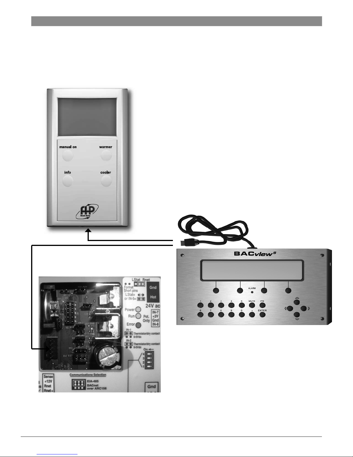
Getting Connected
Connect the BACview module (or laptop if using
Virtual BACview) to the FHP controller, or to an RS
Sensor connected to the controller.
Quick Start Guide
8733914716 DDC (2014/02) Subject to change without prior notice Quick Start Guide
Page 11
Quick Start Guide
Conguring Application Parameters
| 11
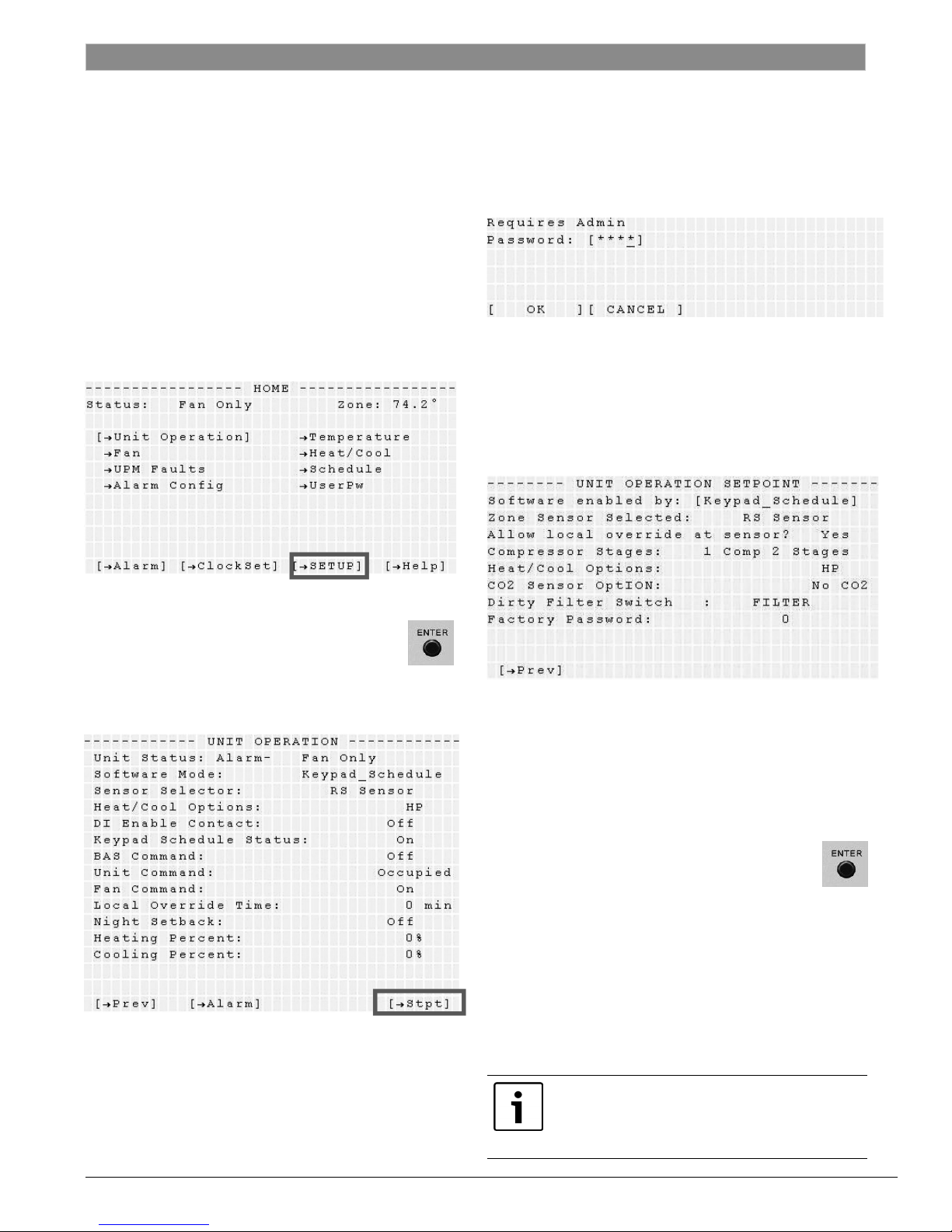
CONFIGURING APPLICATION
PARAMETERS USING BACVIEW
Verify that the different parameters of the
controller program match the application of the
Heat Pump system.
1. Maneuver from the Standby Screen to the
HOME screen by pressing any key on the
BACview.
2. Depending on the software version, either
select the ["SETUP] soft-key label (if available)
using the corresponding soft-key:
3. A 4-character password is required to modify
the Unit Operation Set-point parameters. The
default administrative password for all FHP
controllers is 1111.
Sample screen shot from Virtual BACview. Actual screen may vary.
4. Maneuver through the different sub-menus and
change parameters to match your application
using the Arrow Keys and the Soft Keys.
Sample screen shot from Virtual BACview. Actual screen may vary.
or use the arrow-keys to highlight the
["UNIT OPERATION] menu and hit the
ENTER button to access the Unit Operation
screen, then select the ["Stpt] soft-key label:
Sample screen shot from Virtual BACview. Actual screen may vary.
Sample screen shot from Virtual BACview. Actual screen may vary.
MODIFYING PARAMETER VALUES
USING BACVIEW:
1. Scroll to the desired parameter to highlight it.
2. Hit the Enter button. The selected
parameter should begin to ash and the
modication soft-key labels should
appear at the bottom of the page.
3. Use the [ DECR ] and [ INCR ] soft-keys to
toggle through and select the preferred
parameter value.
4. Use the [ OK ] or [ CANCEL ] soft-keys to save
or discard all changes respectively.
Quick Start Guide Subject to change without prior notice 8733914716 DDC (2014/02)
Based on the heat pump application chosen,
additional screens may need to be congured.
Consult the Bacview instruction manual for
detailed information.
Page 12
12 |
Customizing Program Features
CUSTOMIZING PROGRAM FEATURES
USING BACVIEW
Verify that the various features of the controller
program match the application of the Heat Pump
system.
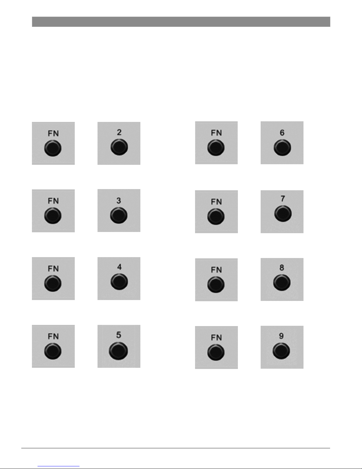
Useful Shortcuts for Tweaking Program
Features Using BACview:
Quick Start Guide
+
Change the User Password
+
Set the Time
+
Access Alarms
+
Change Inactivity Timeout
+
Modify Tuning Parameters
+
Change Temperature Offsets
+
Change BACnet ID
8733914716 DDC (2014/02) Subject to change without prior notice Quick Start Guide
+
Access I/O Status & Overrides
Page 13
Quick Start Guide
Congurable I/O Port Assignments
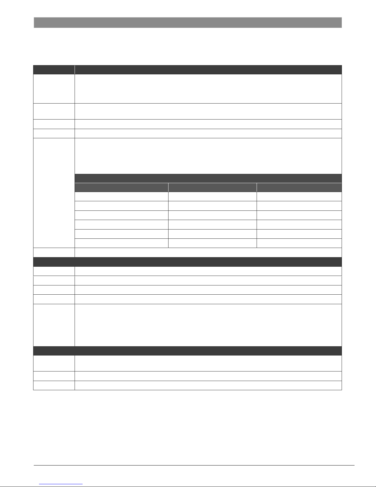
CONFIGURABLE I/O PORT ASSIGNMENTS (SW 7.03.06)
PORT INPUT PORTS
Digital Input Enable
IN-1
IN-2
IN-3* Leaving Water Temperature Sensor
IN-4* UPM Input
IN-5
IN-6* Discharge Air Temperature
DO-1* Fan
DO-2* Reversing Valve
DO-3* Compressor Stage 1
DO-4* Compressor Stage 2
DO-5**
AO-1
AO-2 Modulating Hot Gas Re-Heat Valve
AO-3 Modulating Outside Air Damper
* Non-congurable, factory assigned I/O parameters
** Only one of six possible combinations per application
Humidity Sensor (0-5V output)
CO2 Sensor (0-5V output)
Static Pressure Sensor (0-5V output)
Humidity Sensor (0-5V output)
Remote Temperature Sensor (OA or Zone)
Filter Switch
Economizer Cooling (Entering Water Temperature Sensor)
Differential Pressure Switch
Secondary Condensate Pan
Boilerless (Entering Water Temperature Sensor)
INPUT EXPANSION MODULE (IEM) COMBINATIONS**
EXPANSION PORT 1 (A) EXPANSION PORT 2 (B) EXPANSION PORT 3 (C)
Dirty Filter Switch Fan Status Switch Valve End Switch
Smoke Detector Switch Fan Status Switch Valve End Switch
Dirty Filter Switch Fan Status Switch Differential Pressure Switch
Smoke Detector Switch Fan Status Switch Dirty Filter Switch
Dirty Filter Switch Fan Status Switch Damper End Switch
Smoke Detector Switch Fan Status Switch Secondary Drain Pan
DIGITAL OUTPUTS
Hot Gas Re-Heat (On/Off)
Fresh Air Damper (On/Off)
Heating Stage 1 (Aux Heat)
Boilerless Control (Aux Heat)
Economizer Cooling
Condenser Water Valve
ANALOG OUTPUTS (FHP 583 only)
Variable Frequency Drive (Blower) ABB Drive or Equivalent
Mix Air Temperature SCR
| 13
Quick Start Guide Subject to change without prior notice 8733914716 DDC (2014/02)
Page 14
14 |
Wiring Diagram
WIRING DIAGRAM
Typical FHP560 Wiring Diagram
Quick Start Guide
8733914716 DDC (2014/02) Subject to change without prior notice Quick Start Guide
Page 15

Quick Start Guide
Notes
| 15
Quick Start Guide Subject to change without prior notice 8733914716 DDC (2014/02)
Page 16

601 N.W. 65th Court
Ft. Lauderdale, FL
33309
Phone: 866-642-3198
Fax: 954-776-5529
www.fhp-mfg.com
8733914716
Revised 2014/02
 Loading...