

Bosch 330-PN-N, 330-PN-L Installation Manual
INDOOR MODEL Flow Modulated with Standing pilot
330 PN
Warning: If the information in this manual is not followed exactly, a fire or
explosion may result causing property damage, personal injury or death.
Do not store or use gasoline or other flammable vapor and liquids in the vicinity
of this or any other appliance.
Improper installation, adjustment, alteration, service or maintenance can
cause injury or property damage. Refer to this manual. For assistance or addi-
tional information consult a qualified installer, service agency or the gas sup-
plier. In the Commonwealth of Massachusetts this product must be installed
by a licensed plumber or gas fitter.
Upon completion of the installation, these instructions should be handed to
the user of the appliance for future reference.
What to do if you smell gas
• Close gas valve. Open windows.
• Do not try to light any appliance.
• Do not touch any electrical switch; do not use any phone in your building.
• Immediately call your gas supplier from a neighbor’s phone. Follow the
gas supplier’s instructions.
• If you cannot reach your gas supplier, call the fire department.
• Installation and service must be performed by a qualified installer, ser-
vice agency or the gas supplier
330-PN-N - for use with Natural Gas / 330-PN-L - for use with Liquefied Petroleum (LP) Gas
6 720 644 951 (2014/11) US
Suitable for heating potable water only - Not approved for space heating purposes
(Intended for variable flow applications with steady cold water inlet temperatures)

6 720 644 951 (2014/11) 330 PN
2 | Index
Index
1 Key to symbols and safety instructions . . . . . . . . . . . . 3
1.1 Key to symbols . . . . . . . . . . . . . . . . . . . . . . . . . . . . 3
1.2 Safety instructions . . . . . . . . . . . . . . . . . . . . . . . . . 3
2 Warning . . . . . . . . . . . . . . . . . . . . . . . . . . . . . . . . . . . . . . 6
3 Appliance details . . . . . . . . . . . . . . . . . . . . . . . . . . . . . . . 7
3.1 330 PN specifications (Technical data) . . . . . . . . 7
3.2 Unpacking the 330 PN heater . . . . . . . . . . . . . . . . 8
3.3 General rules to follow for safe operation . . . . . . . 8
3.4 Dimensions and installation clearances . . . . . . . . . 9
4 Installation instructions . . . . . . . . . . . . . . . . . . . . . . . . 10
4.1 Introduction . . . . . . . . . . . . . . . . . . . . . . . . . . . . . . 10
4.2 Proper location for installing your heater . . . . . . 10
4.3 Heater placement and clearances . . . . . . . . . . . . 11
4.4 Mounting Heater . . . . . . . . . . . . . . . . . . . . . . . . . . 11
4.5 Combustion air requirements . . . . . . . . . . . . . . . . 12
4.6 Venting . . . . . . . . . . . . . . . . . . . . . . . . . . . . . . . . . 13
4.6.1Horizontal venting . . . . . . . . . . . . . . . . . . . . . . . . . 13
4.6.2Vertical venting . . . . . . . . . . . . . . . . . . . . . . . . . . . 13
4.7 Gas piping & connections . . . . . . . . . . . . . . . . . . . 15
4.8 Measuring gas pressure . . . . . . . . . . . . . . . . . . . . 19
4.9 Water connections. . . . . . . . . . . . . . . . . . . . . . . . 19
4.10 Recirculation application . . . . . . . . . . . . . . . . . . . 20
5 Operation instructions . . . . . . . . . . . . . . . . . . . . . . . . . 20
5.1 For your safety read before operating your
water heater . . . . . . . . . . . . . . . . . . . . . . . . . . . . . 20
5.2 Lighting instructions . . . . . . . . . . . . . . . . . . . . . . . 21
5.3 To turn off appliance . . . . . . . . . . . . . . . . . . . . . . . 22
5.4 Setting the water temperature . . . . . . . . . . . . . . . 22
5.5 Draining water from heater . . . . . . . . . . . . . . . . . . 23
6 Maintenance and service . . . . . . . . . . . . . . . . . . . . . . . 23
6.1 Maintenance intervals . . . . . . . . . . . . . . . . . . . . . . 23
6.2 Water valve . . . . . . . . . . . . . . . . . . . . . . . . . . . . . . 23
6.3 Pilot . . . . . . . . . . . . . . . . . . . . . . . . . . . . . . . . . . . . 23
6.4 Main burners . . . . . . . . . . . . . . . . . . . . . . . . . . . . . 24
6.5 Vent assembly / heat exchanger . . . . . . . . . . . . . . 24
6.6 Mineral scale build-up . . . . . . . . . . . . . . . . . . . . . . 24
6.6.1Descaling heat exchanger . . . . . . . . . . . . . . . . . . . 24
7 Troubleshooting . . . . . . . . . . . . . . . . . . . . . . . . . . . . . . 25
7.1 Introduction . . . . . . . . . . . . . . . . . . . . . . . . . . . . . . 25
7.2 Pilot does not light . . . . . . . . . . . . . . . . . . . . . . . . 25
7.3 Pilot lights, but goes out when button is released 25
7.4 Pilot goes out during or after hot water use . . . . . 25
7.5 Burners do not light with water flow . . . . . . . . . . 26
7.6 Hot water temperature fluctuates at tap . . . . . . . 26
7.7 Water is too hot . . . . . . . . . . . . . . . . . . . . . . . . . . . 27
7.8 Water is not hot enough . . . . . . . . . . . . . . . . . . . . 27
7.9 Burners ignite without hot water flow . . . . . . . . . 27
7.10 Low hot water pressure . . . . . . . . . . . . . . . . . . . . 27
7.11 Noise when heater is running . . . . . . . . . . . . . . . . 28
7.12 Burners do not operate cleanly; yellow flames
when operating . . . . . . . . . . . . . . . . . . . . . . . . . . . 28
8 Protecting the environment . . . . . . . . . . . . . . . . . . . . 28
9 Interior components and diagram parts list . . . . . . . 29
9.1 Interior components . . . . . . . . . . . . . . . . . . . . . . . 29
9.2 Components diagram . . . . . . . . . . . . . . . . . . . . . . 30
9.3 Parts list . . . . . . . . . . . . . . . . . . . . . . . . . . . . . . . . . 31
10 LIFETIME LIMITED WARRANTY FOR BOSCH
TANKLESS WATER HEATERS . . . . . . . . . . . . . . . . . . . 32
11 Installer Checklist to be completed by installer
upon installation . . . . . . . . . . . . . . . . . . . . . . . . . . . . . . 34
6 720 644 951 (2014/11)330 PN
Key to symbols and safety instructions | 3
1 Key to symbols and safety instructions
1.1 Key to symbols
Warnings
The following keywords are defined and can be used in this
document:
• DANGER indicates a hazardous situation which, if not
avoided, will result in death or serious injury.
• WARNING indicates a hazardous situation which, if not
avoided, could result in death or serious injury.
• CAUTION indicates a hazardous situation which, if not
avoided, could result in minor to moderate injury.
• NOTICE is used to address practices not related to
personal injury.
Important information
Additional symbols
1.2 Safety instructions
Read all instructions before installing. Perform the steps in the
indicated sequence. Have the water heater inspected by a
trained service technician at least once every year. Failure to
comply with these instructions can result in severe, possibly
fatal, personal injury as well as damage to property and
equipment.
Installation and servicing
▶ Risk of fire when soldering and brazing!
Take appropriate protective measures when soldering and
brazing around combustible and flammable material.
▶ Ensure that only a licensed contractor installs or services
the water heater.
▶ On hot components use only material with adequate
temperature stability.
Installation and commissioning
▶ In the Commonwealth of Massachusetts, the water heater
must be installed by a licensed plumber.
▶ Do not install this device in rooms with a high moisture level
(e.g. bathrooms, saunas).
Function
▶ To ensure that the water heater functions properly, follow
these installation and maintenance instructions.
▶ Never close the blow-off line of the T&P safety valve. For
safety reasons, water may escape during heating.
If you smell gas
▶ Turn off the gas shut-off valve.
▶ Open windows and doors.
▶ Do not try to light the appliance.
▶ Do not touch any electrical switch, telephone, and do not
use outlets.
▶ Extinguish all open flames. Do not smoke! Do not use
lighters!
▶ Warn all occupants of the building. Do not ring doorbells!
▶ If you can hear gas leaking, leave the building immediately.
▶ Prevent others from entering the building and notify the
police and fire department from outside the building.
▶ From outside the building, call the gas utility company and
a trained and certified installer.
If you smell flue gas
▶ Switch off the appliance.
▶ Open windows and doors.
▶ Inform a trained and certified installer.
Insufficient ventilation may cause toxic flue gas to escape.
Risk of poisoning.
▶ Never close off or reduce the size of the air intake and outlet
openings.
▶ The appliance must not be operated until any obstructions
have been removed.
▶ Inform the system operator in writing of the problem and
the associated dangers.
Warnings in this document are identified by
a warning triangle printed against a grey
background.
Keywords at the start of a warning indicate
the type and seriousness of the ensuing risk
if measures to prevent the risk are not taken.
This symbol indicates important information
where there is no risk to people or property.
Symbol Explanation
▶ Step in an action sequence
Cross-reference to another part of the
document
• List entry
– List entry (second level)
Table 1

6 720 644 951 (2014/11) 330 PN
4 | Key to symbols and safety instructions
Danger from escaping flue gases
▶ Ensure all vent pipes and chimneys are not damaged or
blocked.
▶ Connect only one appliance to each vent system or
chimney liner.
▶ The venting system piping must not feed into another air
extraction duct.
▶ Do not route the flue system piping through or inside
another air extraction duct.
Danger of explosion of flammable gases
▶ Work on gas components may only be carried out by a
trained and certified installer.
▶ Installation, gas and flue connection, initial commissioning,
electrical connections and annual maintenance must only
be carried out by a trained and certified installer.
Combustion air
▶ Keep the combustion air free of corrosive substances
(halogenated hydrocarbons that contain chlorine or
fluorine compounds).
Never shut off safety valves!
▶ Water may escape from the safety valve at any time when
the water is being heated.
inspection/maintenance
▶ servicing and repairs may only be carried out by a trained
and certified installer.
▶ immediately correct all faults to prevent system damage.
▶ use only bosch spare parts! damage caused by the use of
parts not supplied by bosch may void the warranty.
instruct the customer
▶ explain to the customer how the appliance works and how
to operate it.
▶ inform the customer that he/she must not carry out any
alterations or repairs.
Danger from electric shock
▶ Ensure that only an authorized contractor performs
electrical work.
▶ Before performing electrical work, disconnect the power
and secure the unit against unintentional reconnection.
▶ Ensure the system has been disconnected from the power
supply.
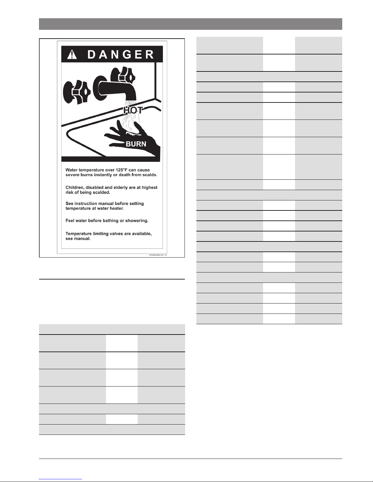
Risk of scalding at the hot water draw-off point
▶ When the water heater is in operation, temperatures in
excess of 122 °F (50 °C) can occur. To limit the
temperature at the tap, install a thermostatic DHW mixing
valve.
▶ Water heated for washing the laundry, dishes and for other
cleaning purposes can cause scalding and permanent
injuries.
▶ Children, elderly, and handicapped persons are more likely
to be permanently injured by hot water. Never leave such
individuals in the tub or shower unattended under any
circumstances. Children must not be allowed to operate
hot water faucets themselves or to fill a bathtub.
▶ If the building has occupants in the above groups who
operate hot water faucets, or state laws / local ordinances
stipulate specific water temperatures, take the following
precautions:
– Use the lowest possible temperature setting.
– To prevent scalding, install a tempering device, such as
an automatic mixing valve, at hot water tap or water
heater. Select and install the automatic mixing valve in
accordance with the valve manufacturer's
recommendations and instructions.
▶ Water exiting from drain valves can be extremely hot. To
avoid injuries:
– Check that all connections are tight.
– Direct exiting water away from people.
▶ Measures must be taken to protect against excessive
temperature and pressure! Installation of a T&P safety
valve is required.
To protect against corrosion and ensure compliance with the
rules for electrical safety, observe the following points:
▶ Use metal fittings for potable water heating systems with
plastic piping.
▶ Use only original accessories from the manufacturer.
▶ When installation of the water heater is complete, inspect
the ground conductor (including metal fittings).
Maintenance
Customers are advised to:
▶ Sign a maintenance and inspection contract with an
authorized contractor. Inspect and maintain the water
heater as necessary and on a yearly basis. Service as
needed.
▶ Use only genuine spare parts.
6 720 644 951 (2014/11)330 PN
Key to symbols and safety instructions | 5
Flooding
▶ After a flood, do not use the appliance if any part has been
submerged. Damage to appliances that have been
submerged can be quite severe and pose numerous safety
risks.
▶ Every appliance that has been submerged must be
replaced.
For your safety
▶ Do not store or use gasoline or other flammable,
combustible or corrosive vapors and liquids in the vicinity
of this or any other appliance.
DANGER: Fatal accidents!
Carbon monoxide poisoning.
▶ Carefully plan where you install the
heater. Correct combustion air supply
and flue pipe installation are very
important. If a gas appliance is not
installed correctly, fatal accidents can
result such as carbon monoxide
poisoning or fire.
DANGER:
Carbon monoxide poisoning.
▶ Exhaust gas must be vented to outside
using approved vent material. See
table 5, page 14 (In Canada use only
ULCS636 approved material). Vent and
combustion air connector piping must
be sealed gas-tight to prevent flue gas
spillage, carbon monoxide emissions
and risk of fire, resulting in severe
personal injury or death. Approved vent
terminations must be used when
penetrating to the outside.
DANGER: Electric shock!
▶ Field wiring connections and electrical
grounding must comply with local
codes, or in the absence of local codes,
with the latest edition of the National
Electric Code, ANSI/NFPA 70, or in
Canada, all electrical wiring must
comply with the local codes and the
Canadian Electrical Code, CSA C22.1
Part 1.
DANGER: Electric shock!
Shock hazard: line voltage is present.
▶ Before servicing the water heater,
unplug power supply cord from outlet.
Failure to do so could result in severe
personal injury or death.
WARNING: Damage to the appliance from
over pressure.
▶ The heater must be disconnected from
the gas supply piping system during
any pressure testing of that system at
test pressures equal to or more than
0.5 psi.
NOTICE:
▶ The appliance should be located in an
area where leakage of the heater or
connections will not result in damage to
the area adjacent to the appliance or to
lower floors of the structure. When such
locations cannot be avoided, it is
recommended that a suitable drain pan,
adequately drained, be installed under
the appliance. The pan must not restrict
combustion air flow.
WARNING:
▶ The maximum inlet gas pressure must
not exceed the value specified by the
manufacturer and the minimum value
listed is for the purpose of input
adjustment.
NOTICE:
▶ If a water heater is installed in a closed
water supply system, such as one
having a backflow preventer in the cold
water supply line, means shall be
provided to control thermal expansion.
Contact the water supplier or local
plumbing inspector on how to control
this situation.
6 720 644 951 (2014/11) 330 PN
6 | Warning
2 Warning
WARNING: Fire danger!
▶ Keep appliance area clear and free from
combustible materials, gasoline and
other flammable vapors and liquids.
NOTICE:
▶ Do not obstruct the flow of combustion
and ventilation air.
NOTICE: Appliance malfunction!
▶ If power is lost while appliance is
operating. Turn off both water and
power for 15 seconds to reset device.
WARNING: Risk of scalding and property
damage.
▶ Precautions must be taken prior to
manually operating the relief valve to
avoid contact with hot water discharged
from the relief valve and to prevent
water damage.
NOTICE: Appliance damage!
▶ Label all wires prior to disconnection
when servicing controls. Wiring errors
can result in improper and dangerous
operation. Verify proper operation after
servicing.
WARNING: System damage!
▶ If a relief valve discharges periodically,
this may be due to thermal expansion in
a closed water supply system. Contact
the water supplier or local plumbing
inspector on how to correct this
situation. Do not plug the relief valve.
WARNING: Property damage!
▶ If the water heater is used in a space
heating application, all piping and
components connected to the water
heater must be suitable for use with
potable water.
WARNING: Personal Injury from toxic
chemicals.
▶ Toxic chemicals, such as those used for
boiler treatment, shall not be
introduced into the potable water used
for space heating.
WARNING: Personal Injury from toxic
chemicals.
▶ A water heater which will be used to
supply potable water shall not be
connected to any heating system or
component(s) previously used with a
nonpotable water heating appliance.
WARNING:
▶ The heater must be isolated from the
gas supply piping system during any
pressure testing of that system at test
pressures equal to or more than 0.5
psig.
CAUTION:
▶ Any changes or modifications not
expressly approved by the party
responsible for compliance could void
the user’s authority to operate the
equipment.
6 720 644 951 (2014/11)330 PN
Appliance details | 7
Fig. 1
3 Appliance details
3.1 330 PN specifications (Technical data)
Approved in US/Canada
Accessories (Bosch part #)
• Pressure relief valve (FWL-2)
Safety devices
• Flame failure device (ionization thermocouple)
• Over heat prevention (temperature limiter)
• Pressure relief valve (Available as accessory)
Capacity
Maximum output BTU/hr
(kW)
58 400 Btu/hr
Maximum input BTU/hr
(kW)
74 900 Btu/hr
Thermal efficiency
(Efficiency in %)
% > 78%
Minimum Input BTU/hr
(kW)
30 735 Btu/hr
Gas Requirement
Gas connection inches ½ ” NPT
Peak load inlet gas pressure
1)
Table 2
Propane water
column
10.5” - 14”
Natural Gas water
column
5.7” - 14”
Water
Hot water connection inches ½ ” NPT
Cold water connection inches ½ ” NPT
Capacity GPM (l/
min)
2.6 (9.8)
Minimum water flow
2)
GPM (l/
min)
0.5 (1.9)
Minimum recommended
water pressure
PSI (bar) 13 PSI (0.9 bar)
Water valve material Fibreglass -
reinforced
polyamide (PA)
Connections: Bottom of heater
Dimensions
Depth inches(mm) 8.66” (220 mm)
Width inches(mm) 12.20” (310 mm)
Height inches(mm) 22.83” (580 mm)
Weight pounds (kg) 26 pounds (12 kg)
Gas types
Natural Gas
LP Gas
Venting
Natural Draft
Minimum height feet 6* with no elbows
Vertical termination
Vent diameter (inches) 4”
1) To measure Gas Pressure, see Measuring Gas Pressure,
chapter 4.8, page 19.
2) Activation varies with inlet water temperatures from 0.5 -
1.6 gallon/minute (1.9 - 6.1 l/m).
Table 2
6 720 644 951 (2014/11) 330 PN
8 | Appliance details
3.2 Unpacking the 330 PN heater
This heater is packed securely.
Before installing the unit, be certain you have the correct
heater for your type of Gas - Propane or Natural Gas.
Identification labels are found on the shipping box, and on the
rating plate which is located on the right side panel of the cover.
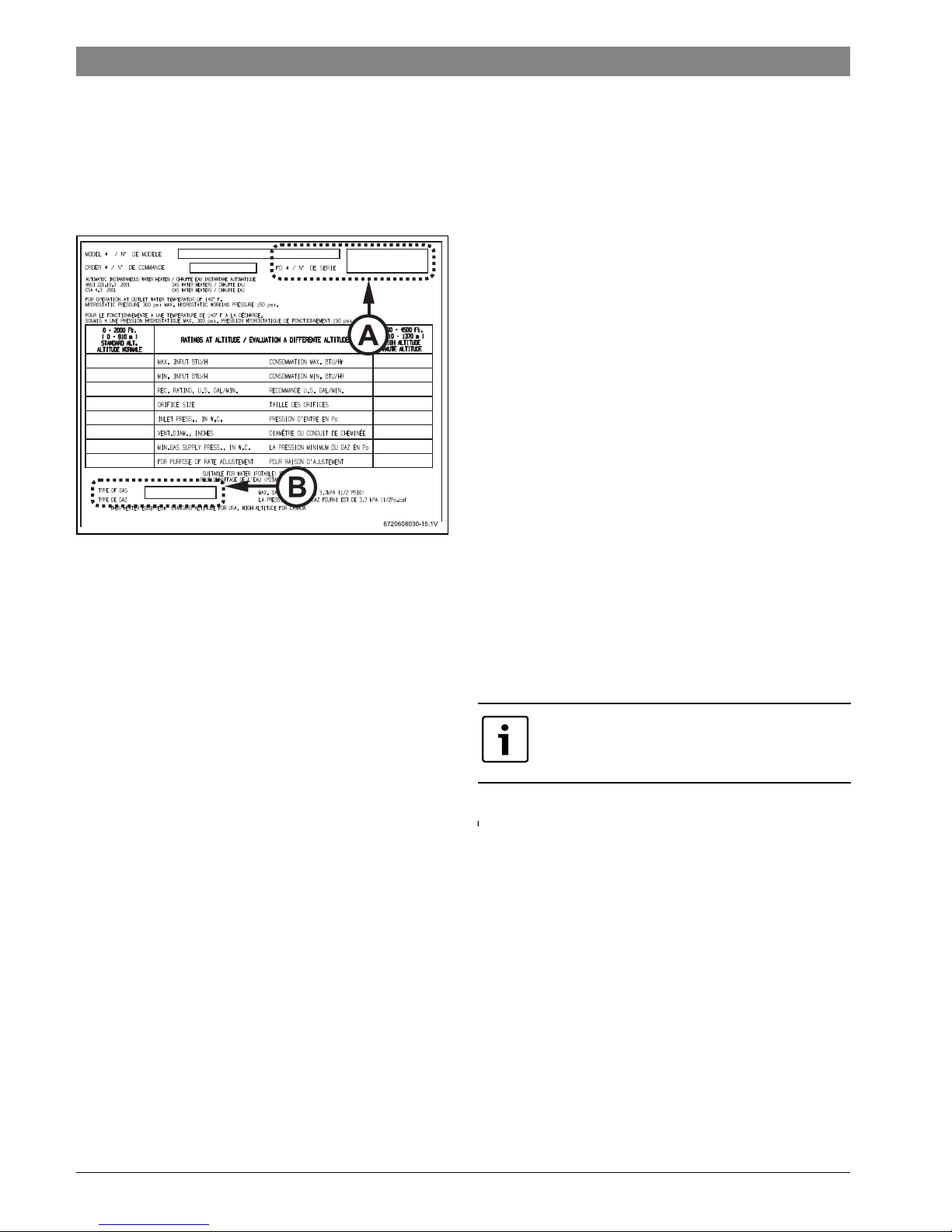
Fig. 2 Rating plate
[A] Serial number
[B] Type of gas
The box includes:
• Mounting screws
• Product registration card
• Installation manual
• Incandescent particle tray
Do not lose this manual, there is a charge for a replacement.
Please complete and return the enclosed product registration
card.
The 330 PN is not approved or designed for:
• Manufactured (mobile) homes, RV's or boats
• Heating or other recirculating/pumping applications*
• Solar/preheat backup or high temperature booster use
• Installation in a bathroom or other occupied rooms
normally kept closed.
* This includes domestic hot water circulator pump loop
systems that may be installed in home hot water system prior to
installing this unit. An approved recirculation design can be
found in chapter 4.10.
3.3 General rules to follow for safe operation
1. You should follow these instructions when you install your
heater. In the United States: The installation must conform with
local codes or, in the absence of local codes, the National Fuel
Gas Code ANSI Z223.1/NFPA 54.
In Canada: The Installation should conform with CGA
B149.(1,2) INSTALLATION CODES and /or local installation
codes.
2. Carefully plan where you install the heater. Proper
clearances must be followed.
3. The appliance must be isolated from the gas supply piping
system by closing its individual manual gas shutoff valve (not
supplied with heater) during any pressure testing at pressures
in excess of ½ Psig (3.5 kPa).
The appliance and its gas connection must be leak tested
before placing the appliance in operation.
4. Keep water heater area clear and free from combustibles
and flammable liquids. Do not locate the heater over any
material which might burn.
5. Correct gas pressure is critical for the optimum operation
of this heater. Gas piping must be sized to provide the required
pressure at the maximum output of the heater, while all the
other gas appliances are in operation. Check with your local gas
supplier, and see chapter 4.7 and 4.8 to verify proper gas line
sizing.
6. Should overheating occur or the gas supply fail to shut off,
turn off the gas supply at the manual gas shut off valve, on the
gas line. Note: manual gas shutoff valve is not supplied with the
heater.
7. Do not use this appliance if any part has been underwater.
Immediately call a qualified service technician to inspect the
appliance and to replace any part of the control system and any
gas control which has been underwater.
BOSCH is constantly improving its products,
therefore specifications are subject to
change without prior notice.
6 720 644 951 (2014/11)330 PN
Appliance details | 9
3.4 Dimensions and installation clearances
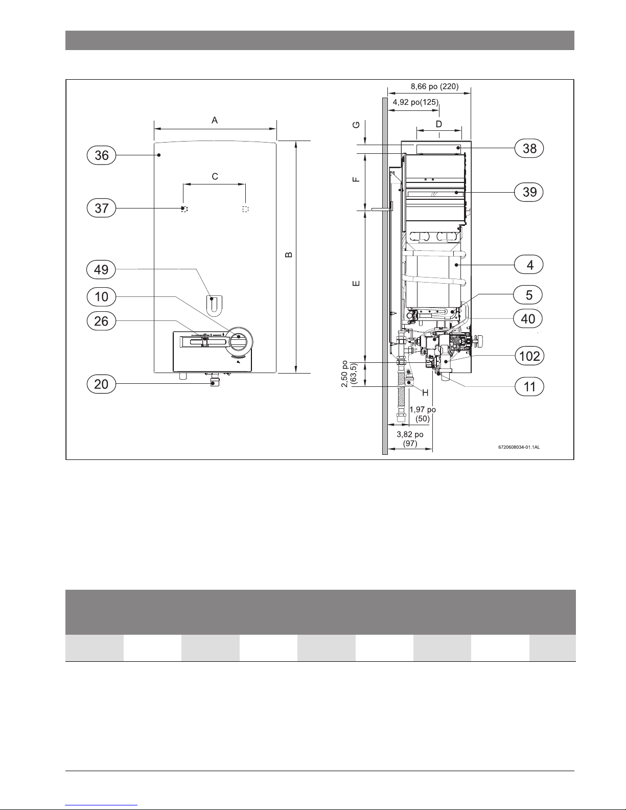
Fig. 3 Dimensions in Inches and (mm)
[4] Heat exchanger
[5] Burner
[10] Temperature control
[11] Water valve
[20] Gas connection
[26] Output control
[36] Front cover
[37] Hole for fixing to wall
[38] Exhaust pipe to connector
[39] Draft diverter with flue gas monitor
[40] Gas valve
[49] Observation window
[102]Piezo
Dimensions
inches (mm)
330 PN A B C D E F G H
12. (310) 22.83”
(580)
9” (228) 4” (100) 20.71”
(526)
2.36” (60) 1” (25) 1/2”
Table 3 Dimensions in inches (mm)
6 720 644 951 (2014/11) 330 PN
10 | Installation instructions
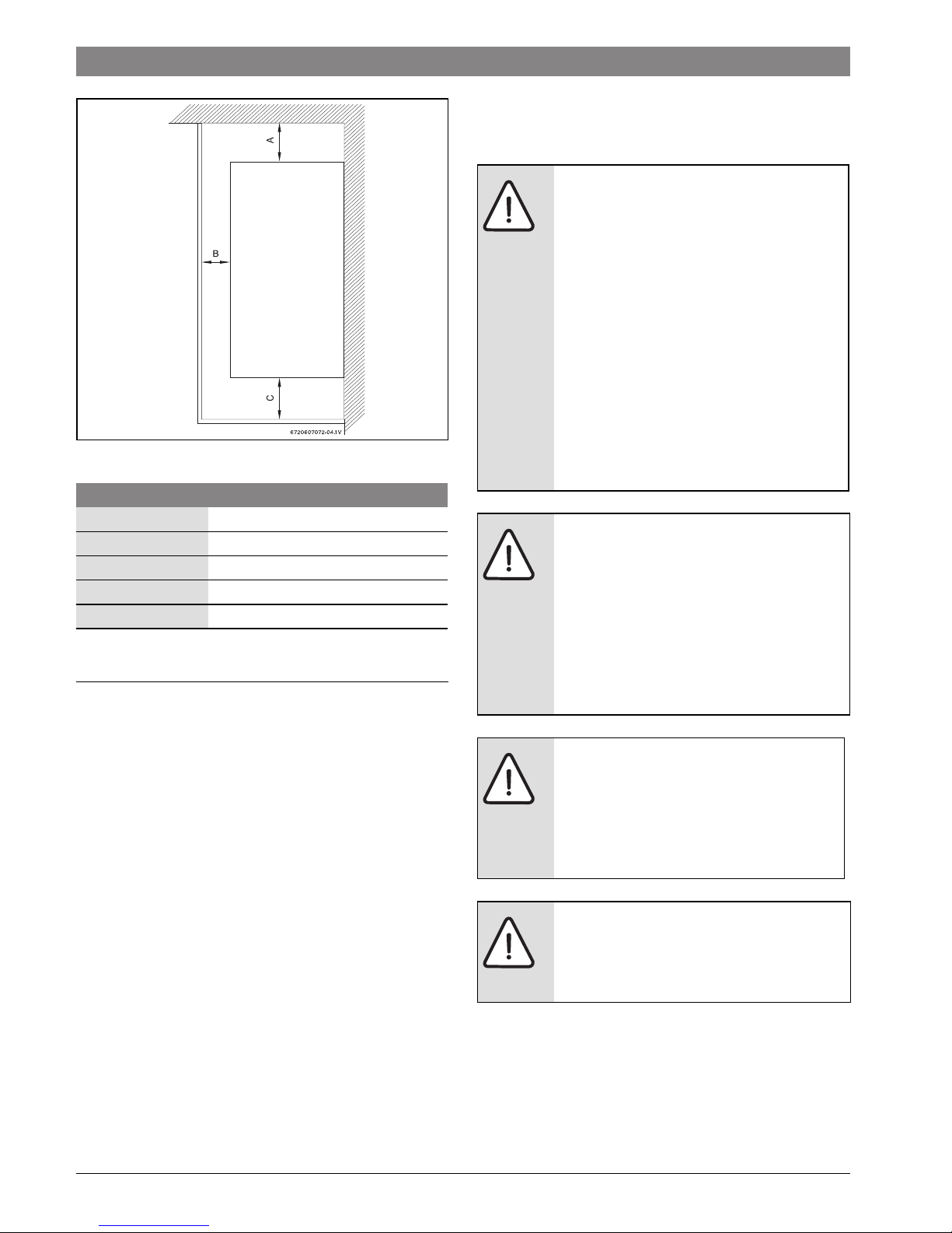
Fig. 4 Minimum clearances
4 Installation instructions
4.1 Introduction
Please follow these instructions. Failure to follow instructions
may result in:
• Damage or injury.
• Improper operation.
• Loss of warranty.
If you are unable to perform the tasks required to install this
heater properly, please contact a locally licensed plumber or
gas technician.
Please contact Bosch Water Heating with any questions.
4.2 Proper location for installing your heater
Carefully select the location of the water heater. For your safety
and for proper heater operation, you must provide combustion
air to the heater and a proper exhaust vent system.
▶ 1. Locate the heater where venting, gas and plumbing
connections are feasible and convenient.
▶ 2. The hot water lines should be kept short to save energy.
Centrally locating the water heater is best. It is always best
to have hot water lines insulated.
Model 330PN
TOP (A) 12 inches (306 mm)
FRONT (B) 4 inches (100 mm)
BACK 0 inches
SIDES 4 inches (100mm)
BOTTOM (C) 12 inches (306 mm)
Table 4
WARNING: The water in this water heater is
cold and always remains cold except for the
times that hot water is being used.
▶ DO NOT INSTALL IN AN AREA WHERE
IT COULD FREEZE.
▶ Drain the heater entirely if freezing
temperatures are anticipated in area
where heater is installed. See chapter
5.5 for draining instructions.
▶ To prevent freeze damage from residual
water in the heater, introduce short
bursts of compressed air (20-40psi)
through these connections to remove
the residual water in the horizontal
pipes and water valve.
WARNING:
▶ Flammable materials, gasoline,
pressurized containers, or any other
items or articles that are potential fire
hazards must NOT be placed on or
adjacent to the heater. The appliance
area must be kept free of all combustible
materials, gasoline and other flammable
vapors and liquids.
WARNING:
▶ The heater must be isolated from the
gas supply piping system during any
pressure testing of that system at test
pressures equal to or more than 0.5
psig.
WARNING:
▶ Place the heater in a location where
water leaks will do NO DAMAGE to
adjacent areas.
6 720 644 951 (2014/11)330 PN
Installation instructions | 11
4.3 Heater placement and clearances
The 330 PN is design certified for installation on a combustible
wall (see 4.4 Mounting installation) provided the wall is not
covered with carpet or other fabric material. For installations in
an alcove or closet, maintain the minimum clearances to
combustible and non-combustible materials listed below. See
also Fig. 4.
A. Top 12 inches (306 mm)
B. Front 4 inches (100 mm)
C. Back 0 inches
D. Sides 4 inches (100 mm)
E. Bottom 12 inches (306 mm)
4.4 Mounting Heater
Remove cover and inspect.
▶ Remove the temperature control.
▶ Unscrew the cover fixing screws, see Fig. 6.
▶ Remove the outer case by sliding it forwards and then
lifting upwards.
▶ Ensure that the flue terminal is clear.
▶ After inspection, replace front cover and tighten screws.
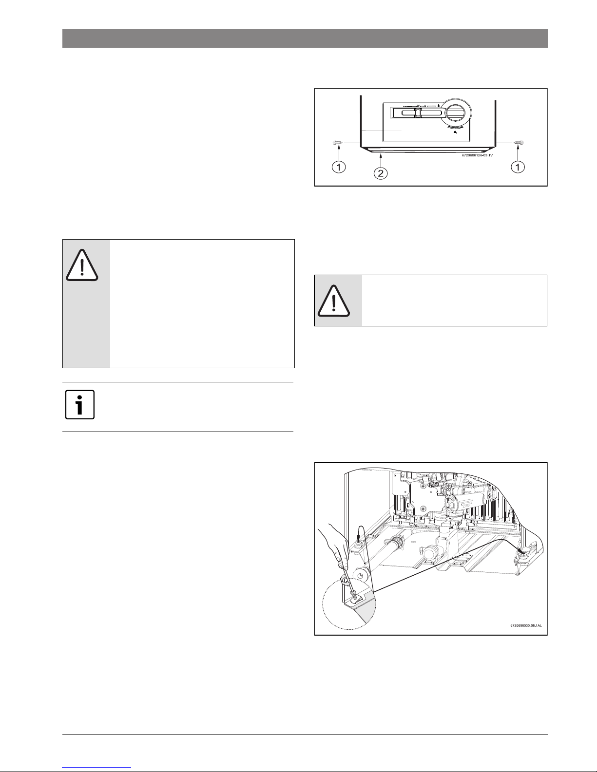
Install incandescent particle tray.
▶ Install incandenscent particle tray using screws provided
as shown in Fig. 5.
Fig. 5 Incandescent particle tray illustration
[1] Screws
[2] Incandescent particle tray
Mounting heater.
The 330 PN is design certified for mounting on a wall.
The heater must be mounted on a wall using appropriate
anchoring materials. If wall is a stud wall sheathed with
plasterboard, it is recommended that support board(s), either
1x4’s or 1/2" (minimum) plywood first be attached across a
pair of studs and then the heater should be attached to the
support boards, see Fig. 7.
▶ Secure the two included L shaped hooks to wall studs or
support board 13 1/4” apart. (See Fig. 7).
▶ Hang heater on two L shaped hooks. (See Fig. 8).
Fig. 6 Remove front cover
WARNING: before starting installation:
▶ check that there are no loose parts
inside the appliance
▶ ensure that gas pipe, gas valve, and
burner have no damage and are
properly fitted.
▶ Read chapter 3.2 to verify proper gas
type and to check all parts are included
in box.
Front cover should be removed in order to
inspect components visually (see
instructions below).
WARNING:
▶ Do not install this appliance on a
carpeted wall.
 Loading...