

BM 2610925947 6-05 6/10/05 10:35 AM Page 1
IMPORTANT: IMPORTANT : IMPORTANTE:
Read Before Using Lire avant usage Leer antes de usar
Operating/Safety Instructions
Consignes de fonctionnement/sécurité
Instrucciones de funcionamiento y seguridad
1644-24
1645-24
Call Toll Free
for Consumer Information
& Service Locations
1-877-BOSCH99 (1-877-267-2499) www.boschtools.com
For English
See page 2 Voir page 17 Ver página 32
Pour renseignement des
consommateurs et centres
de service, appelez au
numéro gratuit :
Parlez-vous français?
Llame gratis para
obtener información
para el consumidor y
ubicaciones de servicio
¿Habla español?

BM 2610925947 6-05 6/10/05 10:35 AM Page 2
General Safety Rules
WARNING
!
all of the warnings listed below refers to your mains-operated (corded) power tool or batteryo
perated (cordless) power tool.
Read all instructions. Failure to follow all instructions listed below may
result in electric shock, fire and/or serious injury.
The term “power tool” in
SAVE THESE INSTRUCTIONS
Work area safety
Keep work area clean and well lit.
Cluttered or dark areas invite accidents.
Do not operate power tools in explosive
atmospheres, such as in the presence of
flammable liquids, gases or dust.
tools create sparks which may ignite the dust
or fumes.
Keep children and bystanders away while
operating a power tool.
cause you to lose control.
Distractions can
Power
Electrical safety
Power tool plugs must match the outlet.
Never modify the plug in any way. Do not
use any adapter plugs with earthed
(grounded) power tools.
and matching outlets will reduce risk of
electric shock.
Avoid body contact with earthed or
grounded surfaces such as pipes,
radiators, ranges and refrigerators.
is an increased risk of electric shock if your
body is earthed or grounded.
Do not expose power tools to rain or wet
conditions.
increase the risk of electric shock.
Do not abuse the cord. Never use the cord
for carrying, pulling or unplugging the
power tool. Keep cord away from heat, oil,
sharp edges or moving parts.
entangled cords increase the risk of electric
shock.
When operating a power tool outdoors,
use an extension cord suitable for
outdoor use.
outdoor use reduces the risk of electric
shock.
Do not use AC only rated tools with a DC
power supply.
work, the electrical components of the AC
rated tool are likely to fail and create a
hazard to the operator.
Water entering a power tool will
Use of a cord suitable for
While the tool may appear to
Unmodified plugs
There
Damaged or
If operating the power tool in damp
locations is unavoidable a Ground Fault
Circuit Interrupter (GFCI) must be used to
supply the power to your tool.
personal protection devices like electrician’s
rubber gloves and footwear will further
enhance your personal safety.
GFCI and
Personal safety
Stay alert, watch what you are doing and
use common sense when operating a
power tool. Do not use a power tool while
you are tired or under the influence of
drugs, alcohol or medication.
inattention while operating power tools may
result in serious personal injury.
Use safety equipment. Always wear eye
protection.
mask, non-skid safety shoes, hard hat, or
hearing protection used for appropriate
conditions will reduce personal injuries.
Avoid accidental starting. Ensure the
switch is in the off-position before
plugging in.
finger on the switch or plugging in power
tools that have the switch on invites
accidents.
Remove any adjusting key or wrench
before turning the power tool on.
or a key left attached to a rotating part of the
power tool may result in personal injury.
Do not overreach. Keep proper footing
and balance at all times.
better control of the power tool in unexpected
situations.
Dress properly. Do not wear loose
clothing or jewelry. Keep your hair,
clothing and gloves away from moving
parts.
be caught in moving parts.
If devices are provided for the connection
of dust extraction and collection facilities,
ensure these are connected and properly
used.
related hazards.
Safety equipment such as dust
Carrying power tools with your
Loose clothes, jewelry or long hair can
Use of these devices can reduce dust-
A moment of
A wrench
This enables
-2-

BM 2610925947 6-05 6/10/05 10:35 AM Page 3
Keep handles dry, clean and free from oil
and grease.
control the power tool.
Slippery hands cannot safely
Power tool use and care
Do not force the power tool. Use the
correct power tool for your application.
The correct power tool will do the job better
and safer at the rate for which it was
designed.
Do not use the power tool if the switch
does not turn it on and off.
that cannot be controlled with the switch is
dangerous and must be repaired.
Disconnect the plug from the power
source and/or the battery pack from the
power tool before making any
adjustments, changing accessories, or
storing power tools.
measures reduce the risk of starting the
power tool accidentally.
Store idle power tools out of the reach of
children and do not allow persons
unfamiliar with the power tool or these
instructions to operate the power tool.
Power tools are dangerous in the hands of
untrained users.
Maintain power tools. Check for
misalignment or binding of moving parts,
breakage of parts and any other condition
that may affect the power tools operation.
If damaged, have the power tool repaired
before use.
poorly maintained power tools.
Keep cutting tools sharp and clean.
Properly maintained cutting tools with sharp
cutting edges are less likely to bind and are
easier to control.
Use the power tool, accessories and tool
bits etc., in accordance with these
instructions and in the manner intended
for the particular type of power tool,
taking into account the working
conditions and the work to be performed.
Use of the power tool for operations different
from those intended could result in a
hazardous situation.
Many accidents are caused by
Any power tool
Such preventive safety
Use clamps or other practical way to
secure and support the workpiece to a
stable platform.
or against your body is unstable and may
lead to loss of control.
Holding the work by hand
Battery tool use and care
Recharge only with the charger specified
by the manufacturer.
suitable for one type of battery pack may
create a risk of fire when used with another
battery pack.
Use battery tools only with specifically
designated battery packs.
battery packs may create a risk of injury and
fire.
When battery pack is not in use, keep it
away from other metal objects like paper
clips, coins, keys, nails, screws, or other
small metal objects that can make a
connection from one terminal to another.
Shorting the battery terminals together may
cause burns or a fire.
Under abusive conditions, liquid may be
ejected from the battery, avoid contact. If
contact accidentally occurs, flush with
water. If liquid contacts eyes, additionally
seek medical help.
battery may cause irritation or burns.
Ensure the switch is in the off position
before inserting battery pack.
battery pack into power tools that have the
switch on invites accidents.
A charger that is
Use of any other
Liquid ejected from the
Inserting the
Service
Have your power tool serviced by a
qualified repair person using only identical
replacement parts.
safety of the power tool is maintained.
Develop a periodic maintenance schedule
for your tool. When cleaning a tool be
careful not to disassemble any portion of
the tool since internal wires may be
misplaced or pinched or safety guard
return springs may be improperly
mounted. Certain cleaning agents such as
gasoline, carbon tetrachloride, ammonia, etc.
may damage plastic parts.
This will ensure that the
SAVE THESE INSTRUCTIONS
-3-

BM 2610925947 6-05 6/10/05 10:35 AM Page 4
Safety Rules for Cordless Reciprocating Saws
Hold tool by insulated gripping surfaces
when performing an operation where the
cutting tool may contact hidden wiring.
Contact with a "live" wire will make exposed
metal parts of the tool "live" and shock the
operator.
Do not drill, fasten or break into
existing walls or other blind areas where
electrical wiring may exist. If this situation is
unavoidable, disconnect all fuses or circuit
breakers feeding this worksite.
Keep hands away from cutting area. Do
not reach under the material being cut.
The proximity of the blade to your hand is
hidden from your sight.
Keep hands from between the gear
housing and saw blade clamp (plunger).
The reciprocating blade clamp (blade
plunger) can pinch your fingers.
Do not use dull or damaged blades. Bent
blades can break easily or cause kickback.
Before starting to cut, turn tool "ON" and
allow the blade to come to full speed.
can chatter or vibrate if blade speed is too
slow at beginning of cut and possibly
kickback.
Always wear safety goggles or eye
protection when using this tool. Use a
dust mask or respirator for applications,
which generate dust.
Secure material before cutting. Never
hold it in your hand or across legs.
Tool
Small
or thin material may flex or vibrate with the
blade, causing loss of control.
Make certain all adjusting screws (knobs)
and the blade clamp are tight before
m
aking a cut.
clamps can cause the tool or blade to slip and
loss of control may result.
When removing the blade from the tool
avoid contact with skin and use proper
protective gloves when grasping the blade
or accessory.
prolonged use.
!
WARNING
grinding, drilling, and other construction
activities contains chemicals known to
cause cancer, birth defects or other
reproductive harm. Some examples of
these chemicals are:
• Lead from lead-based paints,
• Crystalline silica from bricks and cement
and other masonry products, and
• Arsenic and chromium from chemicallytreated lumber.
Your risk from these exposures varies,
depending on how often you do this type of
work. To reduce your exposure to these
chemicals: work in a well ventilated area, and
work with approved safety equipment, such
as those dust masks that are specially
designed to filter out microscopic particles.
L
oose adjusting screws and
Accessories may be hot after
Some dust created by
power sanding, sawing,
Battery/Charger
Before using battery charger, read all
instructions and cautionary markings on
(1) battery charger, (2) battery pack, and
(3) product using battery.
Use only the charger which accompanied
your product or direct replacement as
listed in the catalog or this manual.
substitute any other charger.
approved chargers with your product. See
Functional Description and Specifications.
Use only Bosch
Do not
Do not disassemble charger or operate the
charger if it has received a sharp blow,
been dropped or otherwise damaged in
any way. Replace damaged cord or plugs
immediately.
damage may result in electric shock or fire.
Do not recharge battery in damp or wet
environment. Do not expose charger to
rain or snow. If battery case is cracked or
otherwise damaged, do not insert into
charger.
Battery short or fire may result.
Incorrect reassembly or
-4-
BM 2610925947 6-05 6/10/05 10:35 AM Page 5
C
harge only Bosch approved rechargeable
batteries.
Specifications. Other types of batteries may
burst causing personal injury and damage.
Charge battery pack in temperatures
above +40 degrees F (4 degrees C) and
below +105 degrees F (41 degrees C).
Store tool and battery pack in locations
where temperatures do not go below 40
degrees F (4 degrees C) or will no exceed
120 degrees F (49 degrees C). Allow
battery pack to return to room temperature
before attempting to charge.
important to prevent serious damage to the
battery cells.
Battery leakage may occur under extreme
usage or temperature conditions. Avoid
See Functional Description and
This is
Battery Care
WARNING
!
away from metal objects.
protect terminals from shorting
place batteries in a tool box or pocket with
nails, screws, keys, etc. Fire or injury may
result.
When batteries are not in
tool or charger, keep them
For example, to
DO NOT
c
ontact with skin and eyes.
liquid is caustic and could cause chemical
burns to tissues. If liquid comes in contact
with skin, wash quickly with soap and water,
then with lemon juice or vinegar. If the liquid
contacts your eyes, flush them with water for
a minimum of 10 minutes and seek medical
attention.
Place charger on flat non-flammable
surfaces and away from flammable
materials when re-charging battery pack.
The charger and battery pack heat during
charging. Carpeting and other heat insulating
surfaces block proper air circulation which
may cause overheating of the charger and
battery pack. If smoke or melting of the case
are observed unplug the charger immediately
and do not use the battery pack or charger.
WARNING
!
tool or charger, always place protective
cap onto end of battery pack.
cap, guards against terminal shorting.
DO NOT PUT BATTERIES INTO FIRE OR
EXPOSE TO HIGH HEAT.
explode.
To prevent fire or injury
when batteries are not in
T
he battery
Protective
They may
Battery Disposal
!
WARNING
remove any component projecting from
the battery terminals.
result. Prior to disposal, protect exposed
terminals with heavy insulating tape to
prevent shorting.
NICKEL-CADMIUM BATTERIES
If equipped with a nickel-cadmium battery, the
battery must be collected, recycled or
disposed of in an environmentally sound
manner.
industry program to collect and recycle these
batteries at the end of their useful life, when
Do not attempt to disassemble the battery or
Fire or injury may
“The EPA certified RBRC
Battery Recycling Seal on the
nickel-cadmium (Ni-Cd)
battery indicates Robert
Bosch Tool Corporation is
voluntarily participating in an
taken out of service in the United States or
Canada. The RBRC program provides a
convenient alterative to placing used Ni-Cd
batteries into the trash or the municipal waste
stream, which may be illegal in your area.
Please call 1-800-8-BATTERY for information
on Ni-Cd battery recycling and disposal
bans/restrictions in your area, or return your
batteries to a Skil/Bosch/Dremel Service
Center for recycling. Robert Bosch Tool
Corporation’s involvement in this program is
part of our commitment to preserving our
environment and conserving our natural
resources.”
NICKEL-METAL HYDRIDE BATTERIES
If equipped with a nickel-metal hydride
battery, the battery can be disposed of in a
municipal solid waste stream.
-5-
A
0
A
A
0
A
BM 2610925947 6-05 6/10/05 10:35 AM Page 6
Symbols
IMPORTANT: Some of the following symbols may be used on your tool. Please study them
and learn their meaning. Proper interpretation of these symbols will allow you to operate the
tool better and safer.
Symbol Name Designation/Explanation
V Volts Voltage (potential)
A Amperes Current
Hz Hertz Frequency (cycles per second)
W Watt Power
kg Kilograms Weight
min
s Seconds Time
n
0
.../min Revolutions or reciprocation per minute Revolutions, strokes, surface speed,
0 Off position Zero speed, zero torque...
1, 2, 3, ... Selector settings Speed, torque or position settings.
I, II, III, Higher number means greater speed
Minutes Time
Diameter Size of drill bits, grinding wheels, etc.
No load speed Rotational speed, at no load
orbits etc. per minute
Infinitely variable selector with off Speed is increasing from 0 setting
Arrow Action in the direction of arrow
Alternating current Type or a characteristic of current
Direct current Type or a characteristic of current
Alternating or direct current Type or a characteristic of current
Class II construction Designates Double Insulated
Construction tools.
Earthing terminal Grounding terminal
Warning symbol Alerts user to warning messages
Ni-Cad RBRC seal Designates Ni-Cad battery recycling
program
This symbol designates
that this tool is listed by
Underwriters Laboratories.
This symbol designates
that this tool is listed by
the Canadian Standards
Association.
This symbol designates
that this tool is listed to
Canadian Standards by
Underwriters Laboratories.
This symbol designates that
this tool is listed by
Underwriters Laboratories,
and listed to Canadian
Standards by Underwriters
Laboratories.
This symbol
designates
that
this tool
complies
to NOM
Mexican
Standards.
-6-
BM 2610925947 6-05 6/10/05 10:35 AM Page 7
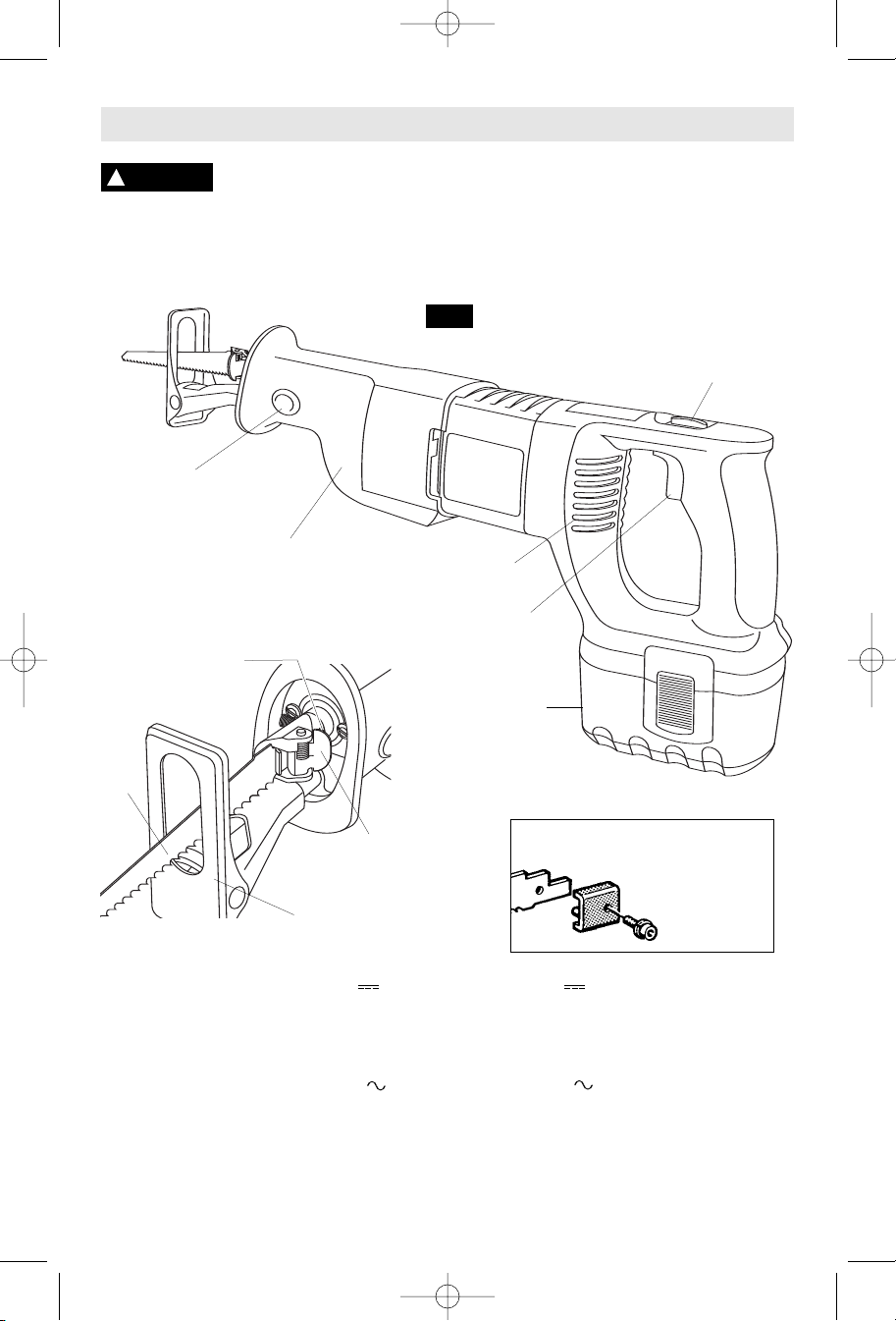
Functional Description and Specifications
WARNING
!
Disconnect battery pack from tool or place the switch in the locked
or off position before making any assembly, adjustments or
changing accessories
tool accidentally.
FOOTPLATE
RELEASE BUTTON
RUBBER BOOT
BLADE
CLAMP SET
SCREW
. Such preventive safety measures reduce the risk of starting the
Cordless Reciprocating Saw
FIG. 1
STROKE LENGTH/
LOCK-OFF SWITCH
AIR VENTS
VARIABLE
SPEED
TRIGGER
BATTERY
PACK
SAW
BLADE
BLADE CLAMP
RELEASE LEVER
ADJUSTABLE
FOOTPLATE
BASIC BLADE
CLAMP
(Optional)
Model Number 1644-24 1645-24
Voltage Rating
18 V
24 V
Stroke Length(s) 3/4”, 1 1/4” (19mm, 32mm) 3/4”, 1 1/4” (19mm, 32mm)
Strokes Per Minute n
0-2,300/min n00-2,300/min
0
Charger BC003, 4, 6, & BC016 BC004, 6, & BC016
BC130 & BC230 BC130 & BC230
Voltage rating 120 V 60 Hz 120 V 60 Hz
Battery pack BAT025 & BAT026 BAT030 & BAT031
BAT160 thru BAT189 BAT240 thru BAT299
BC006 charger requires 12 V DC input
NOTE: ONLY USE CHARGERS LISTED ABOVE
-7-
BM 2610925947 6-05 6/10/05 10:35 AM Page 8
Operating Instructions
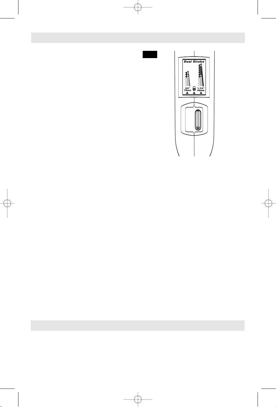
STROKE LENGTH/LOCK-OFF SWITCH
Your tool is equipped with a dual stroke-length
/ lock-off switch located on the top of the saw.
This lever is designed for choosing the stroke
length and for locking the trigger in the "OFF"
position to help prevent accidental starts and
accidental battery discharge. The tool should
be at a complete stop before changing stroke
lengths. For the 3/4" (19 mm) stroke, move
the switch to the far left. For the 1-1/4" (32
mm) stroke, move the switch to the far right.
To activate the trigger lock, move the switch to
the center position (Fig 2).
The 1-1/4" (32 mm) stroke is useful for fast,
aggressive cutting, especially in wood.
The 3/4" (19 mm) stroke offers a wide
variety of benefits:
• Reduced vibration of workpiece when
cutting thin or fragile workpiece materials,
such as sheet metal, thin plywood, or
plaster-and-lath walls.
• Reduced depth-of-cut and blade projection
beyond the far edge of the workpiece, such
as when cutting into a wall or when cutting
a pipe that runs along a wall.
• Easier pocket/plunge cutting.
• Precise starts of cuts.
• Increased pulling power (like a drill has
more torque in low gear).*
• Less heat from lower blade travel speed,
thus longer blade life.*
*These characteristics are especially
beneficial when cutting metal.
BRAKE
When the trigger switch is released it activates
the brake to stop the saw quickly. This is
especially useful when making repetitive cuts.
FIG. 2
VARIABLE SPEED CONTROLLED
TRIGGER SWITCH
Your tool is equipped with a variable speed
controlled trigger switch. The tool can be
turned "ON" or "OFF" by squeezing or
releasing the trigger. The blade plunger
stroke rate can be adjusted from the minimum
to maximum nameplate stroke rate by the
pressure you apply to the trigger. Apply more
pressure to increase the speed and release
pressure to decrease speed.
Higher speed settings are generally used for
fast cutting or when softer cutting materials
such as wood, composite materials, and
plastics. Slower speed settings are generally
used when precision is required or when
cutting harder materials. Materials typically cut
using slower speeds include sheet metal,
conduit, and pipe.
Preparing the Saw
BLADE SELECTION
No one blade can be efficient on all cutting
jobs. Different materials require specially
designed blades. Since your reciprocating
saw can cut so many materials, many types of
BOSCH blades are available. Be sure to use
the proper blade to insure proper cutting
performance.
-8-
BM 2610925947 6-05 6/10/05 10:35 AM Page 9
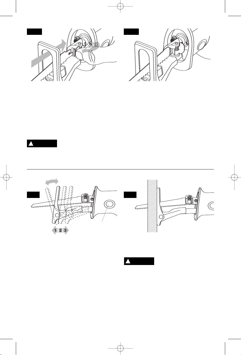
FIG. 3
Simply press the release lever forward to open
the tool-less clamp; insert the blade until it
stops and release the lever (Fig. 3). The
spring-loaded mechanism will lock the clamp
against the blade (Fig. 4). Push in and pull out
on the blade to be sure the pin in the clamp
housing goes through the hole in the blade to
hold the blade securely. The blade may be
inserted with the teeth facing down or up.
!
the footplate for the entire stroke length. Do
not use specialty blades that are very short or
INSTALLING A BLADE
WARNING
Make sure that the front end
of the blade extends through
(a)
FIG. 4
those with a significant cant. Blade must not
contact footplate. A blade which is too short or
canted could jam inside the foot and snap.
NOTE: If you require a basic (Allen wrench)
blade clamp for any reason (extra thick
blades, very thin blades, etc.) an optional
basic blade clamp kit is sold separately. It
contains a clamp, Allen wrench, screw and
lock washer. To use the basic clamp, remove
the tool-less clamp assembly by unscrewing
the setscrew that holds it onto the draw bar.
Then assemble the basic clamp with the
screw and lock washer provided (Fig. 1).
FIG. 5
(b)
FOOTPLATE ADJUSTMENT
The footplate tilts in order to keep as much of
its surface in contact with the work surface
Fig. 5 (a).
The footplate assembly can also be locked
into one of three projection positions to
optimize blade life and/or to reduce blade
protrusion beyond the end of the footplate,
such as when cutting into large diameter pipe
or into walls. To adjust the footplate position,
simply push the footplate release button and
move the footplate into the desired position.
The locking mechanism is spring-loaded to
lock into one of the 3 positions on the footplate
assembly. If the footplate is pulled out so far
that a notch shows at the other end of the
FOOTPLATE
RELEASE BUTTON
FIG. 6
shaft, the footplate assembly is extended too
far out, and must be retracted to the one of
the 3 positions Fig. 5 (b).
!
WARNING
It will cause the footplate to release from the
desired settings and you may lose control and
be injured.
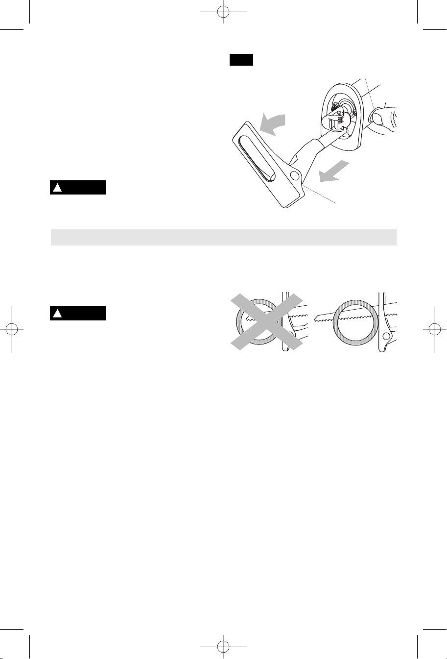
To reduce the risk of injury, be sure the blade
extends beyond the footplate and all the way
through the workpiece throughout the stroke.
Blades may shatter if the blade hits the
footplate or hits the work at an angle that is
nearly head-on (Fig. 6).
Do not push the footplate
release button while sawing.
-9-
BM 2610925947 6-05 6/10/05 10:35 AM Page 10
To remove the footplate assembly for
servicing (Fig. 7):
1. Remove the blade.
2. Press and hold footplate release button in.
3. Pull the footplate assembly out as far as it
will go.
4. Rotate it clockwise (as viewed from the
back of the saw) about 90 degrees until it
releases.
5. Pull footplate assembly completely out.
To re-insert, reverse this process.
!
WARNING
the footplate will cause instability, expose the
blade, and may damage the spindle.
Always use tool with the
footplate. Using tool without
Using the Saw
1. Securely clamp the work.
2. Mark the line of cut and grasp the tool with
one hand on the handle and the other
placed on the insulated rubber boot over
the front housing.
!
WARNING
housing. If you saw into a blind area where
live wiring exists, you may be shocked or
electrocuted.
3. Keep the saw footplate firmly against the
work to minimize counter-force (jumping)
and vibration.
4. Squeeze the trigger to start the tool. Let the
saw reach full speed before starting the cut.
Guide the saw so that the blade will move
along the marked line.
Following a few simple tips will reduce the
wear on the workpiece, the tool and the
operator.
1. Blades cut on the draw or back stroke. On
fine work, such as paneling, fiberglass, etc.,
place the good side of workpiece facing
down.
2. Use the correct saw blade for the material
being cut and keep extra blades on hand to
use when others become dull. Replace
cracked or bent blades immediately.
3. Select the appropriate stroke length and
footplate projection settings, as well as the
appropriate cutting speed.
4. To reduce the risk of injury, be sure the
blade always extends beyond the footplate
Always operate the saw with
the insulated boot on the front
SAWING TIPS
FIG. 7
and work throughout the stroke. Blades
may shatter if the front on the blade hits the
work and/or the footplate.
WRONG RIGHT
5. When cutting metal:
- Use the 3/4” (19 mm) stroke length to
achieve (less vibration, less heat, and
longer blade life).
- Apply a lubricant for easier, smoother,
faster cutting and longer blade life.
- For non-ferrous metals, aluminum,
bronze or brass, use a stick wax on the
blade.
- For ferrous metals, iron and steel, use
machine or cutting oil along the surface
to be cut.
6. When cutting thin metal, "sandwich" the
material between two pieces of scrap wood.
Clamp or put in a bench vise. One piece of
lumber on top of the metal can be used with
adequate clamping. Place your cut lines or
design on the wood. Use the 3/4" (19 mm)
stroke for reduced vibration in the material.
7.
Don’t force the cutting. Let the saw and
blade do the work.
FOOTPLATE
RELEASE
BUTTON
FOOTPLATE
ASSEMBLY
-10-
BM 2610925947 6-05 6/10/05 10:35 AM Page 11
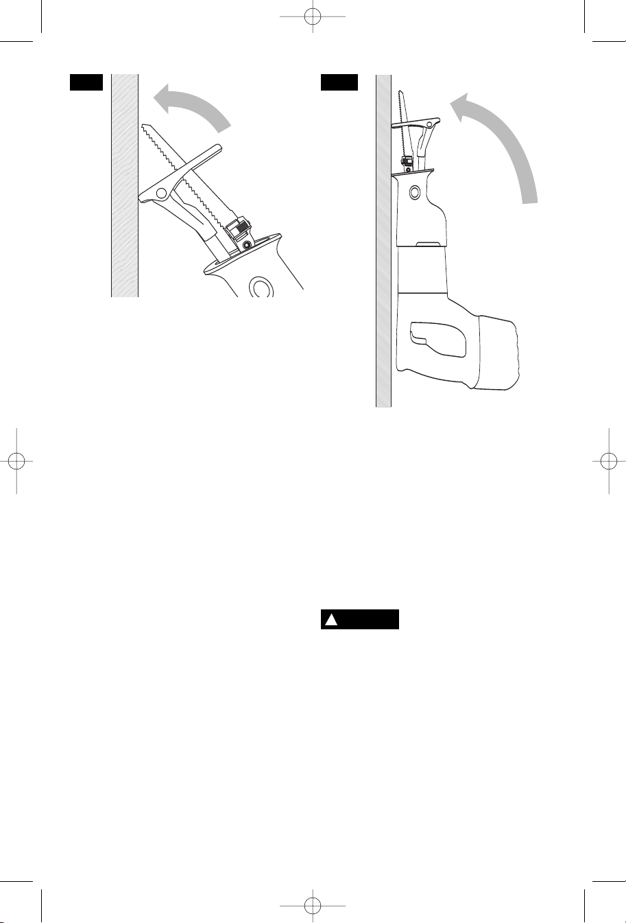
FIG. 8 FIG. 9
The reciprocating saw can be used to make
plunge cuts into softer material, (for example,
wood or light building materials for walls),
without a starting hole (Fig. 8).
1. Mark the line to be cut clearly on the work.
2. Adjust the footplate position or change
3. Set the stroke length selector switch to the
4. Set the tool with the bottom edge of the
5. Place the tip of the blade (not running) on
6. Tilt the saw back so that the blade clears
7. Squeeze the trigger switch and carefully tilt
8.
9.
10. Continue sawing as needed.
POCKET/PLUNGE CUTS
blades as necessary.
3/4" (19 mm) stroke length.
footplate firmly against the material.
the line to be cut.
the work.
the tool forward to engage the moving saw
blade into the material.
After the blade penetrates through the work,
stop the saw and position it so that the front
of the footplate rests firmly against the
work.
Chose the appropriate stroke length for the
material, 3/4" (19 mm) or 1-1/4" (32 mm)
To make plunge cutting easier, use a heavy
gauge blade, install the blade with the teeth
facing upward, and hold the saw upside down
as shown (Fig. 9).
Do not plunge cut in metal surfaces.
In thick materials and in harder materials,
such as metal, plunge cutting should not be
attempted. Such materials can be cut with the
recip saw only by starting the cut from the
edge of the material or from a hole drilled all
the way through the material that is large
enough to fit the saw blade.
!
WARNING
may create a hazard.
NOTES:
The use of any accessories
not specified in this manual
-11-
BM 2610925947 6-05 6/10/05 10:35 AM Page 12
RELEASING AND INSERTING BATTERY PACK
Release battery pack from tool by pressing on
both sides of the battery release tabs and pull
downwards. Before inserting battery pack,
remove protective cap from battery pack.
To insert battery, align battery and slide
IMPORTANT CHARGING NOTES
1. The battery pack accepts only about 80% of
its maximum capacity with its first few charge
cycles. However, after the first few charge
cycles, the battery will charge to full capacity.
2. The charger was designed to fast charge
the battery only when the battery temperature
is between 40˚F (4˚C) and 105˚F (41˚C).
3. A substantial drop in operating time per
charge may mean that the battery pack is
nearing the end of its life and should be
replaced.
4. If you anticipate long periods (i.e. a month
or more) of non-use of your tool, it is best to
run your tool down until it is fully discharged
before storing your battery pack. After a long
period of storage, the capacity at first recharge
will be lower. Normal capacity will be restored
in two or three charge/discharge cycles.
battery pack into tool until it locks into
position. Do not force.
Remember to unplug charger during storage
period.
5. If battery does not charge properly:
in some other electrical device.
light switch which turns power “off” when lights
are turned off.
Clean with cotton swab and alcohol if
necessary.
take or send tool, battery pack and charger to
your local Bosch Service Center. See “Tools,
Electric” in the Yellow Pages for names and
addresses.
Note: Use of chargers or battery packs not
sold by Bosch will void the warranty.
a. Check for voltage at outlet by plugging
b. Check to see if outlet is connected to a
c. Check battery pack terminals for dirt.
d. If you still do not get proper charging,
CHARGING BATTERY PACK (30 MINUTE SINGLE BAY-BC130)
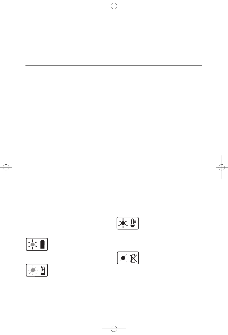
INDICATORS, SYMBOLS AND MEANING
If the indicator lights are “OFF”, the charger
is not receiving power from power supply
outlet.
If the green indicator light is
“ON”, the charger is plugged in
but the battery pack is not
inserted, or the battery pack is fully charged
and is being trickle charged.
If the green indicator light is
“BLINKING”, the battery pack is
being fast-charged. Fastcharging will automatically stop when the
battery pack is fully charged.
If the red indicator light is “ON”,
the battery pack is too hot or
cold for fast-charging. The
charger will switch to trickle charge, until a
suitable temperature is reached, at which
time the charger will switch automatically to
fast-charging.
If the red indicator light is
“BLINKING”, the battery pack
cannot accept a charge or the
contacts of the charger or battery pack are
contaminated. Clean the contacts of the
charger or battery pack only as directed in
these operating instructions or those
supplied with your tool or battery pack.
-12-
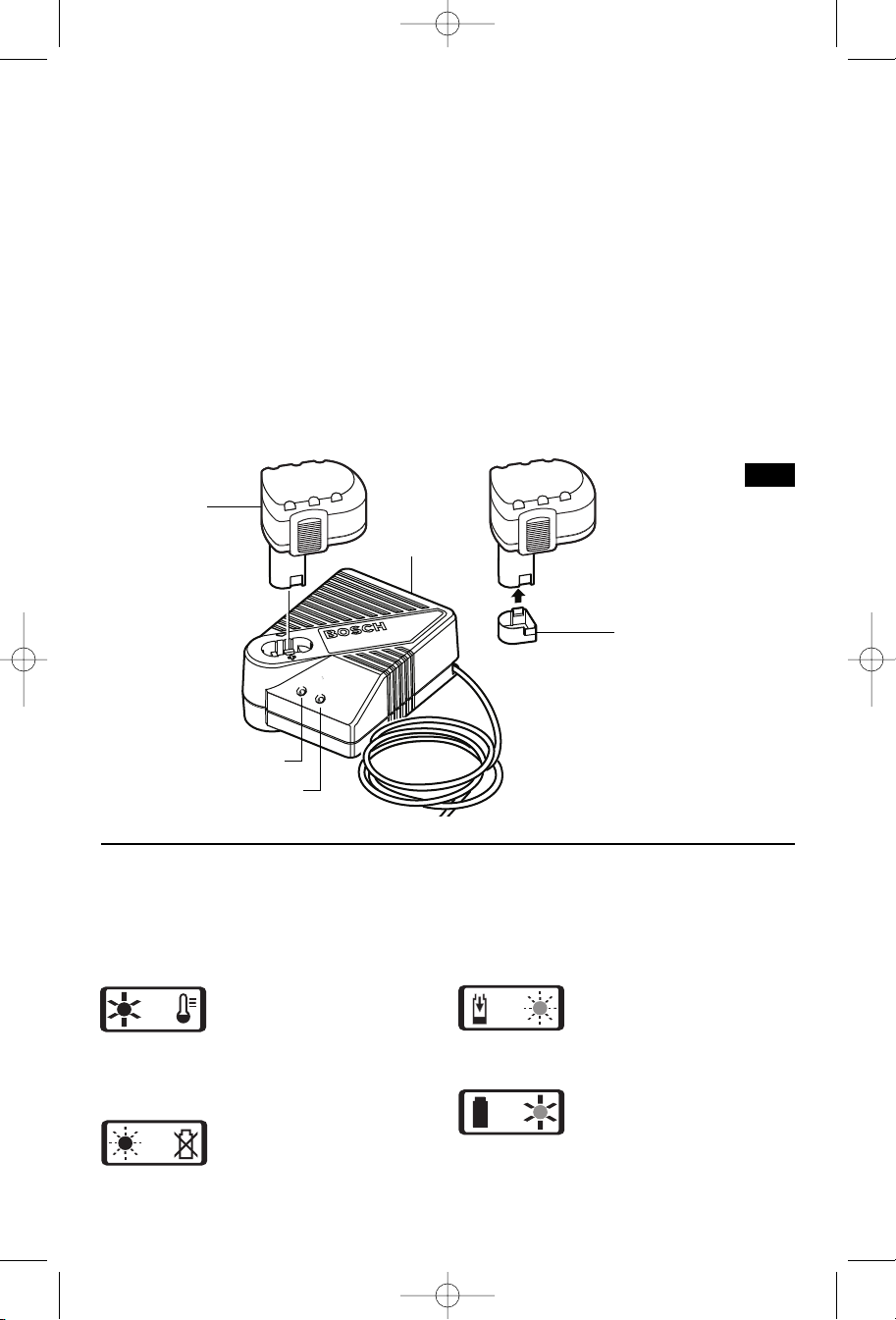
BM 2610925947 6-05 6/10/05 10:35 AM Page 13
Plug charger cord into your standard power
outlet. Before inserting battery pack, remove
protective cap, then insert battery pack into
charger (Fig. 10).
T
he charger’s green indicator light will begin to
“BLINK”. This indicates that the battery is
receiving a fast charge. Fast-charging will
automatically stop when the battery pack is
fully charged.
When the indicator light stops “BLINKING”
(and becomes a steady green light) fast
charging is complete.
The battery pack may be used even though
the light may still be blinking. The light may
require more time to stop blinking depending
on temperature. When you begin the charging
process of the battery pack, a steady red light
BATTERY
PACK
CHARGER
could also mean the battery pack is too hot or
too cold.
The purpose of the green light is to indicate
that the battery pack is fast-charging. It does
not indicate the exact point of full charge. The
light will stop blinking in less time if the battery
p
ack was not completely discharged.
When charging several batteries in sequence,
the charge time may slightly increase.
When the battery pack is fully charged,
unplug the charger (unless you're charging
another battery pack) and slip the battery
pack back into the tool.
To prevent fire or injury when batteries are
not in tool or charger, always place protective
cap onto end of battery pack.
FIG. 10
PROTECTIVE
CAP
RED LIGHT
GREEN LIGHT
CHARGING BATTERY PACK (30 MINUTE DUAL BAY-BC230)
INDICATORS, SYMBOLS AND MEANING
If the indicator lights are “OFF”, the charger
is not receiving power from power supply
outlet.
If the red indicator light is
“ON”, the battery pack is too
hot or cold for fast-charging.
The charger will switch to trickle charge, until
a suitable temperature is reached, at which
time the charger will switch automatically to
fast-charging.
If the red indicator light is
“BLINKING”, the battery pack
cannot accept a charge or
the contacts of the charger or battery pack
are contaminated. Clean the contacts of the
charger or battery pack only as directed in
these operating instructions or those
supplied with your tool or battery pack.
If the green indicator light is
“BLINKING”, the battery pack
is being fast-charged. Fastcharging will automatically stop when the
battery pack is fully charged.
If the green indicator light is
“ON”, the charger is plugged
in but the battery pack is not
inserted, or the battery pack is fully charged
and is being trickle charged.
-13-
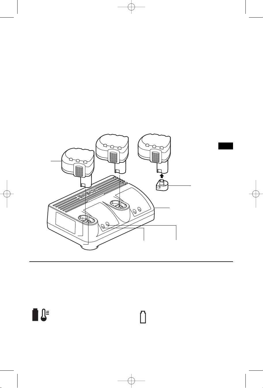
BM 2610925947 6-05 6/10/05 10:35 AM Page 14
Plug charger cord into your standard power
outlet. Before inserting battery pack, remove
protective cap, then insert battery pack into
charger (Fig. 11).
The charger’s green indicator light will begin to
“BLINK”. This indicates that the battery is
receiving a fast charge. Fast-charging will
automatically stop when the battery pack is
fully charged.
When the indicator light stops “BLINKING”
(and becomes a steady green light) fast
charging is complete.
The battery pack may be used even though
the light may still be blinking. The light may
require more time to stop blinking depending
on temperature. When you begin the
charging process of the battery pack, a
BATTERY
PACK
steady red light could also mean the battery
pack is too hot or too cold.
The purpose of the green light is to indicate
that the battery pack is fast-charging. It does
not indicate the exact point of full charge.
The light will stop blinking in less time if the
battery pack was not completely discharged.
When charging several batteries in
sequence, the charge time may slightly
increase.
When the battery pack is fully charged,
unplug the charger (unless you're charging
another battery pack) and slip the battery
pack back into the tool.
To prevent fire or injury when batteries are
not in tool or charger, always place protective
cap onto end of battery pack.
FIG. 11
PROTECTIVE
CAP
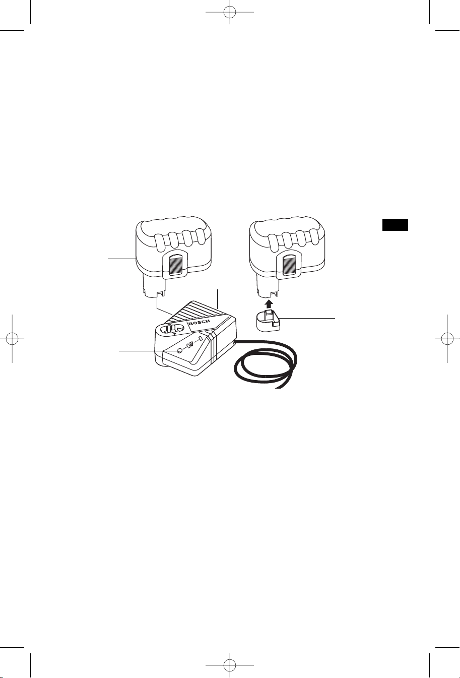
CHARGING BATTERY PACK (1 HOUR CHARGER)
INDICATORS, SYMBOLS AND MEANING
If the indicator lights are “OFF”, the charger
is not receiving power from power supply
outlet.
If the green indicator light is “ON”,
the charger is plugged in but the
battery pack is not inserted, or the
battery pack is fully charged and is being
trickle charged, or the battery pack is too hot
or cold for fast-charging. The charger will
CHARGER
RED LIGHT
GREEN LIGHT
switch to trickle charge, until a suitable
temperature is reached, at which time the
charger will switch automatically to fastcharging.
If the green indicator light is
“BLINKING”, the battery pack is
being fast-charged. Fast-charging
will automatically stop when the battery pack
is fully charged.
-14-
BM 2610925947 6-05 6/10/05 10:35 AM Page 15
CHARGING BATTERY PACK (1 HOUR CHARGER)
Plug charger cord into your standard power
outlet. Before inserting battery pack, remove
p
rotective cap, then insert battery pack into
c
harger (Fig. 12).
The charger’s green indicator will begin to
“
BLINK”. This indicates that the battery is
receiving a fast charge. Fast-charging will
automatically stop when the battery pack is
fully charged.
When the indicator light stops “BLINKING”
(and becomes a steady green light) fast
charging is complete.
When you begin the charging process of the
mean the battery pack is too hot or too cold.
The purpose of the light is to indicate that the
battery pack is fast-charging. It does not
indicate the exact point of full charge. The
light will stop blinking in less time if the
b
attery pack was not completely discharged.
When the battery pack is fully charged,
unplug the charger (unless you're charging
another battery pack) and slip the battery
pack back into the tool handle.
To prevent fire or injury when batteries are
not in tool or charger, always place protective
cap onto end of battery pack.
battery pack, a steady green light could also
BATTERY
PACK
CHARGER
FIG. 12
INDICATOR
LIGHT
PROTECTIVE
CAP
-15-
 Loading...