

Operating/Safety Instructions
Consignes de fonctionnement/sécurité
Instrucciones de funcionamiento
y seguridad
IMPORTANT: IMPORTANT : IMPORTANTE:
Read Before Using Lire avant usage Leer antes de usar
For English Parlez-vous français? ¿Habla español?
See page 2 Voir page 9 Ver página 16
Consumer Information
Renseignement des consommateurs
Información para el consumidor
Toll Free Number: Appel gratuit : Número de teléfono gratuito:
1-877-BOSCH99 (1-877-267-2499) http://www.boschtools.com.
1638
B115 5
BM 2610995759 11/00 11/16/00 11:50 AM Page 1
Read and understand all instructions. Failure to follow all instructions
listed below, may result in electric shock, fire and/or serious personal injury.
SAVE THESE INSTRUCTIONS
-2-
Work Area
Keep your work area clean and well lit.
Cluttered benches and dark areas invite
accidents.
Do not operate power tools in explosive
atmospheres, such as in the presence of
flammable liquids, gases, or dust. Power
tools create sparks which may ignite the dust
or fumes.
Keep by-standers, children, and visitors
away while operating a power tool.
Distractions can cause you to lose control.
Electrical Safety
Double Insulated tools are equipped with
a polarized plug (one blade is wider than
the other.) This plug will fit in a polarized
outlet only one way. If the plug does not
fit fully in the outlet, reverse the plug. If it
still does not fit, contact a qualified
electrician to install a polarized outlet. Do
not change the plug in any way. Double
Insulation eliminates the need for the
three wire grounded power cord and
grounded power supply system. Before
plugging in the tool, be certain the outlet
voltage supplied is within the voltage marked
on the nameplate. Do not use “AC only”
rated tools with a DC power supply.
Avoid body contact with grounded surfaces
such as pipes, radiators, ranges and
refrigerators. There is an increased risk of
electric shock if your body is grounded. If
operating the power tool in damp locations is
unavoidable, a Ground Fault Circuit Interrupter
must be used to supply the power to your
tool. Electrician’s rubber gloves and footwear
will further enhance your personal safety.
Don't expose power tools to rain or wet
conditions. Water entering a power tool will
increase the risk of electric shock.
Do not abuse the cord. Never use the cord
to carry the tools or pull the plug from an
outlet. Keep cord away from heat, oil, sharp
edges or moving parts. Replace damaged
cords immediately. Damaged cords increase
the risk of electric shock.
When operating a power tool outside, use
an outdoor extension cord marked "W-A"
or "W." These cords are rated for outdoor use
and reduce the risk of electric shock. Refer to
“Recommended sizes of Extension Cords” in
the Accessory section of this manual.
Personal Safety
Stay alert, watch what you are doing and
use common sense when operating a
power tool. Do not use tool while tired or
under the influence of drugs, alcohol, or
medication. A moment of inattention while
operating power tools may result in serious
personal injury.
Dress properly. Do not wear loose clothing
or jewelry. Contain long hair. Keep your
hair, clothing, and gloves away from
moving parts. Loose clothes, jewelry, or long
hair can be caught in moving parts. Keep
handles dry, clean and free from oil and
grease.
Avoid accidental starting. Be sure switch is
“OFF” before plugging in. Carrying tools with
your finger on the switch or plugging in tools
that have the switch “ON” invites accidents.
Remove adjusting keys or wrenches before
turning the tool “ON”. A wrench or a key that
is left attached to a rotating part of the tool
may result in personal injury.
Do not overreach. Keep proper footing and
balance at all times. Proper footing and
balance enables better control of the tool in
unexpected situations.
Use safety equipment. Always wear eye
protection. Dust mask, non-skid safety
shoes, hard hat, or hearing protection must be
used for appropriate conditions.
Tool Use and Care
Use clamps or other practical way to
secure and support the workpiece to a
stable platform. Holding the work by hand or
against your body is unstable and may lead to
loss of control.
Do not force tool. Use the correct tool for
your application. The correct tool will do the
!
WARNING
Power Tool Safety Rules
BM 2610995759 11/00 11/16/00 11:50 AM Page 2

-3-
Rotary Cutter Safety Rules
job better and safer at the rate for which it is
designed.
Do not use tool if switch does not turn it
“ON” or “OFF”. Any tool that cannot be
controlled with the switch is dangerous and
must be repaired.
Disconnect the plug from the power source
before making any adjustments, changing
accessories, or storing the tool. Such
preventive safety measures reduce the risk of
starting the tool accidentally.
Store idle tools out of reach of children and
other untrained persons. Tools are
dangerous in the hands of untrained users.
Maintain tools with care. Keep cutting tools
sharp and clean. Properly maintained tools,
with sharp cutting edges are less likely to bind
and are easier to control. Any alteration or
modification is a misuse and may result in a
dangerous condition.
Check for misalignment or binding of
moving parts, breakage of parts, and any
other condition that may affect the tools
operation. If damaged, have the tool
serviced before using. Many accidents are
caused by poorly maintained tools. Develop a
periodic maintenance schedule for your tool.
Use only accessories that are recommended by the manufacturer for your
model. Accessories that may be suitable for
one tool, may become hazardous when used
on another tool.
Service
Tool service must be performed only by
qualified repair personnel. Service or
maintenance performed by unqualified
personnel could result in a risk of injury. For
example: internal wires may be misplaced or
pinched, safety guard return springs may be
improperly mounted.
When servicing a tool, use only identical
replacement parts. Follow instructions in
the Maintenance section of this manual.
Use of unauthorized parts or failure to follow
Maintenance Instructions may create a risk of
electric shock or injury. Certain cleaning
agents such as gasoline, carbon tetrachloride,
ammonia, etc. may damage plastic parts.
Hold tool by insulated gripping surfaces
when performing an operation where the
cutting tool may contact hidden wiring or
its own cord. Contact with a "live" wire will
make exposed metal parts of the tool "live"
and shock the operator. If cutting into
existing walls or other blind areas where
electrical wiring may exist is unavoidable,
disconnect all fuses or circuit breakers
feeding this worksite.
Always make sure the work surface is
free from nails and other foreign objects.
Cutting into a nail can cause the bit and the
tool to jump and damage the bit.
Never hold the workpiece in one hand and
the tool in the other hand when in use.
Never place hands near or below cutting
surface. Clamping the material and guiding
the tool with both hands is safer.
Never lay workpiece on top of hard
surfaces, like concrete, stone, etc...
Protruding cutting bit may cause tool to
jump.
Always wear safety goggles and dust
mask. Use only in well ventilated area.
Using personal safety devices and working
in safe environment reduces risk of injury.
After changing the bits or making any
adjustments, make sure the collet nut and
any other adjustment devices are
securely tightened. Loose adjustment
device can unexpectedly shift, causing loss
of control, loose rotating components will be
violently thrown.
Never start the tool when the bit is
engaged in the material. The bit cutting
edge may grab the material causing loss of
control of the cutter.
Always hold the tool with two hands
during start-up. The reaction torque of the
motor can cause the tool to twist.
The direction of feeding the bit into the
material is very important and it relates to
the direction of bit rotation. When
viewing the tool from the top, the bit
rotates clockwise. Feed direction of
BM 2610995759 11/00 11/16/00 11:50 AM Page 3

cutting must be counter-clockwise.
NOTE: inside and outside cuts will require
different feed direction, refer to section on
feeding the router. Feeding the tool in the
wrong direction, causes the cutting edge of
the bit to climb out of the work and pull the
tool in the direction of this feed.
Never use dull or damaged bits. Sharp
bits must be handled with care. Damaged
bits can snap during use. Dull bits require
more force to push the tool, possibly
causing the bit to break.
Never touch the bit during or immediately
after the use. After use the bit is too hot to
be touched by bare hands.
Never lay the tool down until the motor
has come to a complete standstill. The
spinning bit can grab the surface and pull
the tool out of your control.
Never use bits that have a cutting
diameter greater than the opening in the
base.
Do not use the tool for drilling purposes.
This tool is not intended to be used with drill
bits.
Always use the tool with the depth guide
securely attached and positioned flat
against material being cut. The guide
securely positioned on the material improves
the stability and control of your tool.
Some dust created by
power sanding, sawing,
grinding, drilling, and other construction
activities contains chemicals known to
cause cancer, birth defects or other
reproductive harm. Some examples of
these chemicals are:
• Lead from lead-based paints,
• Crystalline silica from bricks and cement
and other masonry products, and
• Arsenic and chromium from chemically-
treated lumber.
Your risk from these exposures varies,
depending on how often you do this type of
work. To reduce your exposure to these
chemicals: work in a well ventilated area,
and work with approved safety equipment,
such as those dust masks that are specially
designed to filter out microscopic particles.
-4-
!
WARNING
BM 2610995759 11/00 11/16/00 11:50 AM Page 4
-5-
IMPORTANT: Some of the following symbols may be used on your tool. Please study them
and learn their meaning. Proper interpretation of these symbols will allow you to operate the
tool better and safer.
Symbol Name Designation/Explanation
V Volts Voltage (potential)
A Amperes Current
Hz Hertz Frequency (cycles per second)
W Watt Power
kg Kilograms Weight
min Minutes Time
s Seconds Time
Diameter Size of drill bits, grinding wheels, etc.
n
0
No load speed Rotational speed, at no load
.../min Revolutions or reciprocation per minute Revolutions, strokes, surface speed,
orbits etc. per minute
0 Off position Zero speed, zero torque...
1, 2, 3, ... Selector settings Speed, torque or position settings.
I, II, III, Higher number means greater speed
Infinitely variable selector with off Speed is increasing from 0 setting
Arrow Action in the direction of arrow
Alternating current Type or a characteristic of current
Direct current Type or a characteristic of current
Alternating or direct current Type or a characteristic of current
Class II construction Designates Double Insulated
Construction tools.
Earthing terminal Grounding terminal
Warning symbol Alerts user to warning messages
Ni-Cad RBRC seal Designates Ni-Cad battery recycling
program
Symbols
0
This symbol designates
that this tool is listed by
Underwriters Laboratories.
This symbol designates
that this tool is listed by
the Canadian Standards
Association.
This symbol designates
that this tool is listed to
Canadian Standards by
Underwriters Laboratories.
This symbol
designates
that
this tool
complies
to NOM
Mexican
Standards.
This symbol designates
that this tool is listed by
Underwriters Laboratories,
and listed to Canadian
Standards by Underwriters
Laboratories.
BM 2610995759 11/00 11/16/00 11:50 AM Page 5
-6-
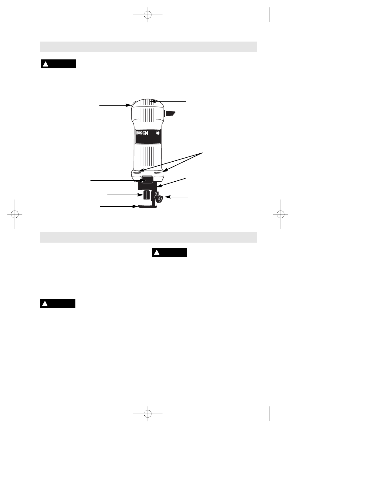
Functional Description and Specifications
B115 5
ON/OFF SLIDE
SWITCH
SHAFT LOCK
EXHAUST
AIR VENTS
INTAKE
AIR VENTS
DEPTH GUIDE
DEPTH GUIDE
LOCKING KNOB
DEPTH GUIDE
BRACKET w/CLIC
COLLET NUT
Disconnect the plug from the power source before making any
assembly, adjustments or changing accessories. Such preventive
safety measures reduce the risk of starting the tool accidentally.
!
WARNING
Operating Instructions
SLIDE "ON/OFF" SWITCH
This tool is switched "ON" by the slide
switch located on the front of the motor
housing.
TO TURN THE TOOL "ON" slide the switch
button up.
TO TURN THE TOOL "OFF" slide the switch
button down or "0" position.
Hold the tool with both
hands while starting, since
torque from the motor can cause the tool to
twist.
INSTALLING BITS
The bits are held by a collet system. Use
either the 1/8" or 1/4" collet depending on
the size of the bit shank.
Do Not Use .118" shank bits in the 1/8"
collet use only BOSCH "SC" series bits or
similar bits with 1/8" (.125") or 1/4" (.250")
shanks.
The bit flutes are sharp and
should be handled with
caution.
Depress and hold the shaft-lock in and
rotate the collet nut and shaft until the shaftlock engages and holds the shaft. Use the
standard equipment wrench to loosen nut
(counter-clockwise). Remove the old bit (if
there is one) insert the new bit as far as
possible, but not so far that the bit flutes
engage the collet (leave approximately 1/8"
of shank exposed). Re-engage the shaftlock and tighten the nut (clockwise) by hand
and then with the wrench until bit is held
securely.
DEPTH GUIDE ADJUSTMENT
Use the depth guide to adjust the depth of
cut. Simply loosen (counter clockwise) the
knob a little (approximately 1/8 turn) and
slide the depth guide in or out to the desired
depth of cut (about 1/8" greater than
material thickness) and retighten the knob
(clockwise).
NOTE: For tool specifications refer to nameplate on your tool.
!
WARNING
Rotary Cutter
!
WARNING
BM 2610995759 11/00 11/16/00 11:50 AM Page 6
-7-
REMOVING AND INSTALLING THE "CLIC"
DEPTH GUIDE ASSEMBLY
The depth guide assembly consists of the
depth guide, locking knob and bracket.
Twist the whole assembly counter clockwise
approximately 1/8 of a turn. Then pull the
whole assembly straight off of the tool. To
re-attach the assembly, align the notched
area of the depth guide bracket with the
protrusion on the spring which is attached to
the tool collar. Then push the assembly over
the collar and twist it clockwise about 1/8
turn until the spring clicks in place.
Disconnect the plug from
the power source before
making any assembly, adjustments or
changing accessories. Such preventive
safety measures reduce the risk of starting
the tool accidentally. Make certain that the
collet nut is securely tightened before
turning the tool on.
MAKING DRYWALL CUT OUTS
After assembling the bit into the tool as
described earlier, it will be necessary to
review the instructions provided below and
make some practice cut-outs with this tool
before attempting an actual job. The best
method is to take some scrap pieces and
nail or screw them in place over wall studs
which have an electrical box or other feature
in place. A few such exercises will give you
the necessary practice to make clean,
professional cutouts around whatever is
behind the drywall you are installing.
Do not attempt to use this
tool to make cut-outs
around any fixture or opening which has
live electrical wires, or on any wall which
may have live electrical wiring behind it,
as the bit could conduct current to the
tool, creating an electrocution hazard for
the operator. Shut off breakers or remove
fuses to disconnect the circuit. Always hold
the tool by its thermoplastic housing, and
always wear eye protection when operating
this device.
•Step 1: Be certain that the box or fixture
which requires a cut-out is firmly mounted
and all wires or other obstructions around
the opening are pushed back out of the way.
The drywall cut-out bit uses the outer edge
of the box or fixture as a guide, so it is
important that there is nothing in the way
which can prevent it from guiding completely
around the opening. For the purposes of this
instruction manual, the procedure discussed
will be to make a cut-out around a standard
2 1/8" x 3 3/4" electrical box.
•Step 2: Before fastening the drywall sheet,
make a mark close to the center of the
opening in the box on the side of the drywall
facing you. You may then begin to screw or
nail the sheet to the wall, but do not install
fasteners closer then about 15" to the box,
or the sheet will likely bulge and crack
before you cut the opening.
•Step 3: Holding the tool firmly switch the
tool to the "ON" position as described
earlier.
•Step 4: Holding the tool firmly with both
hands, push the bit through the drywall at
the mark you made in step 2. Guide the bit
to the right until you feel it make contact with
the inside edge of the box. Then retract the
bit slightly, (do not pull entirely out) to allow
it to penetrate through the drywall and
contact the outside edge of the box by
continuing to move the tool slightly to the
right as you cut.
•Step 5: Keeping the bit in contact with the
outside of the box, move the tool counterclockwise to create the opening. When
rounding a corner, keep applying light
pressure towards the center of the box while
moving the bit steadily and smoothly around
the whole box until the entire cut has been
completed. Slide the switch to the "OFF"
position, and pull the bit free of the drywall.
You may then remove the piece you have
cut, and you will have a smooth opening.
The rest of the screws or nails may now be
put in place on the drywall sheet, and the
task is completed.
The motor may stall if
improperly used or overloaded. Reduce the pressure or feed rate to
prevent possible damage to the tool. Do not
attempt to start the tool when the bit is
engaged in the workpiece. Always be sure
the collet nut is tightened securely before
use.
MAKING CUT-OUTS IN MATERIALS
OTHER THAN DRYWALL
Your tool is capable of cutting many types of
building materials in addition to drywall.
There are several different bits available for
use on these materials. Most materials can
be cut with the "wood" bit, however the
"carbide" burr bits must be used for hard,
abrasive materials such as ceramic WALL
tile (will not work on ceramic FLOOR grade
tile), cement board, plaster etc.
To make cut-outs, insert and adjust the
proper bit according to previous instructions.
Hold the tool firmly and turn it on. Place the
depth guide at about a 45º angle against the
!
WARNING
!
WARNING
!
CAUTION
BM 2610995759 11/00 11/16/00 11:50 AM Page 7
-8-
Service
Preventive maintenance
performed by unauthorized personnel may result in misplacing
of internal wires and components which
could cause serious hazard. We
recommend that all tool service be
performed by a Bosch Factory Service
Center or Authorized Bosch Service Station.
TOOL LUBRICATION
Your Bosch tool has been properly
lubricated and is ready to use. It is
recommended that tools with gears be
regreased with a special gear lubricant at
every brush change.
CARBON BRUSHES
The brushes and commutator in your tool
have been engineered for many hours of
dependable service. To maintain peak
efficiency of the motor, we recommend
every two to six months the brushes be
examined. Only genuine Bosch replacement
brushes specially designed for your tool
should be used.
BEARINGS
After about 300-400 hours of operation, or at
every second brush change, the bearings
should be replaced at Bosch Factory Service
Center or Authorized Bosch Service Station.
Bearings which become noisy (due to heavy
load or very abrasive material cutting) should
be replaced at once to avoid overheating or
motor failure.
Cleaning
To avoid accidents always
disconnect the tool from
the power supply before cleaning or
performing any maintenance. The tool may
be cleaned most effectively with
compressed dry air. Always wear safety
goggles when cleaning tools with
compressed air.
Ventilation openings and switch levers must
be kept clean and free of foreign matter. Do
not attempt to clean by inserting pointed
objects through openings.
Certain cleaning agents
and solvents damage
plastic parts. Some of these are: gasoline,
carbon tetrachloride, chlorinated cleaning
solvents, ammonia and household
detergents that contain ammonia.
!
WARNING
!
WARNING
Maintenance
!
CAUTION
If an extension cord is
necessary, a cord with
adequate size conductors that is capable
of carrying the current necessary for your
tool must be used. This will prevent
excessive voltage drop, loss of power or
overheating. Grounded tools must use 3wire extension cords that have 3-prong
plugs and receptacles.
NOTE: The smaller the gauge number, the
heavier the cord.
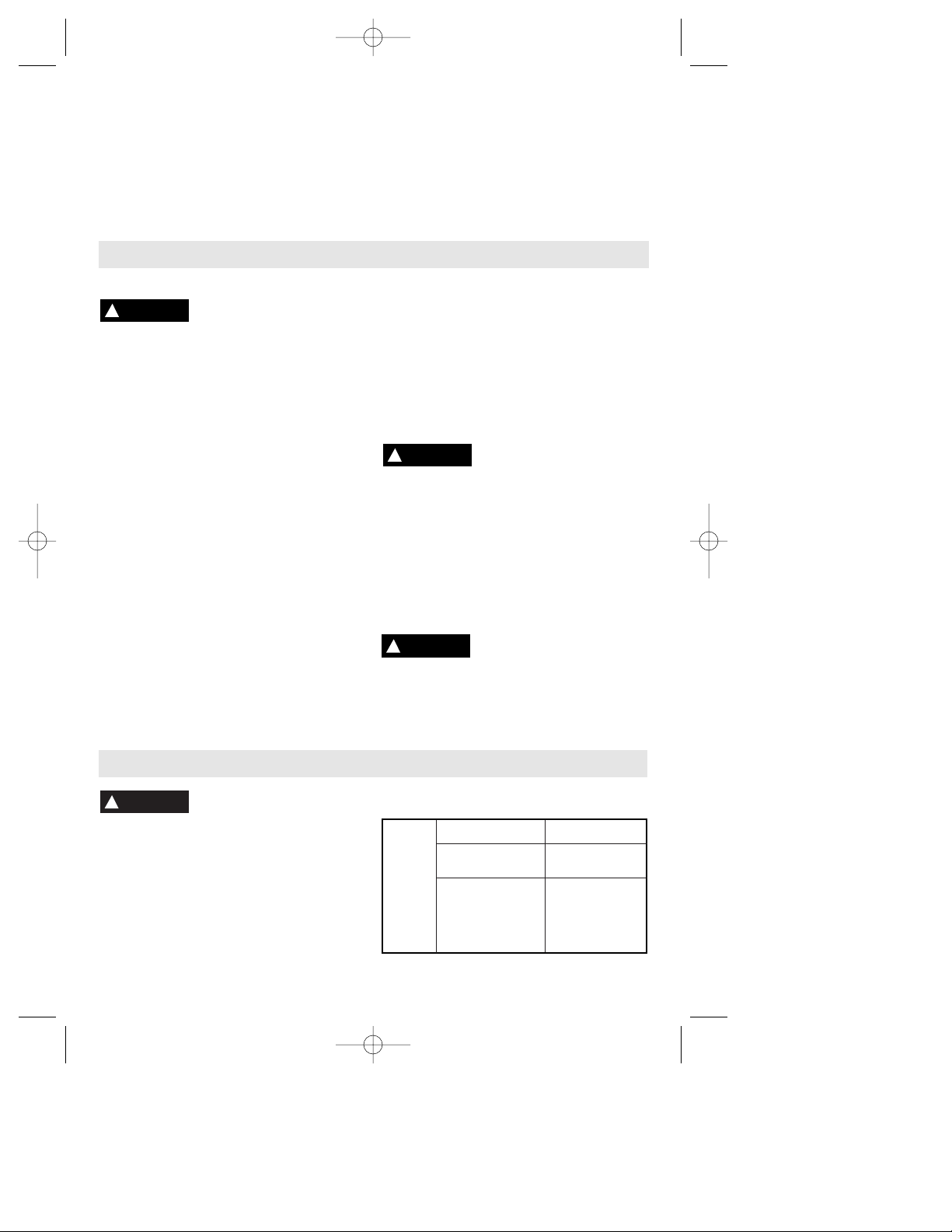
RECOMMENDED SIZES OF EXTENSION CORDS
120 VOLT ALTERNATING CURRENT TOOLS
Tool’s
Ampere
Rating
Cord Size in A.W.G.
Wire Sizes in mm
2
3-6
6-8
8-10
10-12
12-16
18 16 16 14 .75 .75 1.5 2.5
18 16 14 12 .75 1.0 2.5 4.0
18 16 14 12 .75 1.0 2.5 4.0
16 16 14 12 1.0 2.5 4.0 —
14 12 — — — — — —
25 50 100 150 15 30 60 120
Cord Length in Feet Cord Length in Meters
!
WARNING
Accessories
work surface and tilt the tool to an upright
position with the bit entering the scrap
portion of the area being cut. Move the bit to
the line you wish to follow and cut in a
clockwise position. Cutting at a slow even
rate will make following a line easier and will
put less stress on the bit.
NOTE: When cutting on a vertical surface,
avoid ending your cut at the bottom of the
hole. If possible, start and end your cut at
the top so the scrap part will not drop onto
the rotating bit. Turn the tool off and remove
it from the cut out hole.
BM 2610995759 11/00 11/16/00 11:50 AM Page 8

-9-
Vous devez lire et comprendre toutes les instructions. Lenon-respect, même
partiel, des instructions ci-après entraîne un risque de choc életrique, d'incendie
et/ou de blessures graves.
CONSERVEZ CES INSTRUCTIONS
Aire de travail
Veillez à ce que l'aire de travail soit propre et bien
éclairée. Le désordre et le manque de lumière
favorisent les accidents.
N'utilisez pas d'outils électriques dans une
atmosphère explosive, par exemple enprésence de
liquides, de gaz ou de poussières inflammables. Les
outils électriques créent des étincelles qui pourraient
enflammer les poussières ou les vapeurs.
Tenez à distance les curieux, les enfants et les
visiteurs pendant que vous travaillezavec un outil
électrique. Ils pourraient vous distraire et vous faire
faire une fausse manoeuvre.
Sécurité électrique
Les outils à double isolation sont équipés d'une fiche
polarisée (une des lames est pluslarge que l'autre),
qui ne peut se brancher que d'une seule façon dans
une prise polarisée. Si la fiche n'entre pas
parfaitement dans la prise, inversez sa position ; si
elle n'entre toujours pasbien, demandez à un
électricien qualifié d'installer une prise de courant
polarisée. Ne modifiez pas la fiche de l'outil. La
double isolation élimine le besoin d'un cordon
d'alimentationà trois fils avec mise à la terre ainsi que
d'une prise de courant mise à la terre.Avant de brancher
l'outil, assurez-vous que la tension de la prise
correspond, à plus ou moins 10 %, à celle indiquée sur
la plaque signalétique. N'utilisez pas d'outils prévus
pour courant alternatif seulement avec une source de
courant continu.
Évitez tout contact corporel avec des surfaces mises à
la terre (tuyauterie, radiateurs, cuisinières,
réfrigérateurs, etc.). Le risque de choc électrique est
plus grand si votre corps est encontact avec la terre.Si
l'utilisation de l'outil électrique dans un endroit humide
est inévitable, un disjoncteur de fuite à la terre doit être
utilisé pour alimenter votre outil. Des chaussures et des
gants en caoutchouc d'électricien contribueront à
accroître davantage votre sécurité personnelle.
N'exposez pas les outils électriques à la pluie ou à
l'eau. La présence d'eau dans un outil électrique
augmente le risque de choc électrique.
Ne maltraitez pas le cordon. Ne transportez pas l'outil
par son cordon et ne débranchez pas la fiche en tirant
sur le cordon. N'exposez pas le cordon à la chaleur, à
des huiles, à des arêtes vives ou à des pièces en
mouvement. Remplacez immédiatement un cordon
endommagé. Un cordon endommagé augmente le
risque de choc électrique.
Lorsque vous utilisez un outil électrique à l'extérieur,
employez un prolongateur pour l'extérieur marqué «
W-A » ou « W ». Ces cordons sont faits pour être
utilisés à l'extérieur et réduisent le risque de choc
électrique. Reportez-vous aux « Dimensions
recommandées des cordons de rallonge » dans la
section Accessoires de ce manuel.
Sécurité des personnes
Restez alerte, concentrez-vous sur votre travail et
faites preuve de jugement. N'utilisez pas un outil
électrique si vous êtes fatigué ou sous l'influence de
drogues, d'alcool ou de médicaments. Un instant
d'inattention suffit pour entraîner des blessures graves.
Habillez-vous convenablement. Ne portez ni
vêtements flottants ni bijoux. Confinez les cheveux
longs. N'approchez jamais les cheveux, les
vêtements ou les gants des pièces en mouvement.
Des vêtements flottants, des bijoux ou des cheveux
longs risquent d'être happés par des pièces en
mouvement. Gardez les poignées sèches, propres et
exemptes d'huile et de graisse.
Méfiez-vous d'un démarrage accidentel. Avant de
brancher l'outil, assurez-vous que son interrupteur
est sur ARRÈT. Le fait de transporter un outil avec le
doigt sur la détente ou de brancher un outil dont
l'interrupteur est en position MARCHE peut mener tout
droit à un accident.
Enlevez les clés de réglage ou de serrage avant de
démarrer l'outil. Une clé laissée dans une pièce
tournante de l'outil peut provoquer des blessures.
Ne vous penchez pas trop en avant. Maintenez un bon
appui et restez en équilibre entout temps. Un bonne
stabilité vous permet de mieux réagir à une situation
inattendue.
Utilisez des accessoires de sécurité. Portez toujours
des lunettes ou une visière. Selon les conditions,
portez aussi un masque antipoussière, des bottes de
sécurité antidérapantes, un casque protecteur et/ou un
appareil antibruit.
Utilisation et entretien des outils
Immobilisez le matériau sur une surface stable au
moyen de brides ou de toute autre façon adéquate. Le
fait de tenir la pièce avec la main ou contre votre corps
offre une stabilité insuffisante et peut amener un
dérapage de l'outil.
Ne forcez pas l'outil. Utilisez l'outil approprié à la
tâche. L'outil correct fonctionne mieux et de façon plus
sécuritaire. Respectez aussi la vitesse de travail qui lui
est propre.
N'utilisez pas un outil si son interrupteur est bloqué.
Un outil que vous ne pouvez pas commander par son
Règles de Sécurité Générales
AVERTISSEMENT
!
BM 2610995759 11/00 11/16/00 11:50 AM Page 9

-10-
Consignes de sécurité pour couteaux rotatifs
interrupteur est dangereux et doit être réparé.
Débranchez la fiche de l'outil avant d'effectuer un
réglage, de changer d'accessoire oude ranger l'outil.
De telles mesures préventives de sécurité réduisent le
risque de démarrage accidentel de l'outil.
Rangez les outils hors de la portée des enfants et
d'autres personnes inexpérimentées. Les outils sont
dangereux dans les mains d'utilisateurs novices.
Prenez soin de bien entretenir les outils. Les outils de
coupe doivent être toujours bien affûtés et propres.
Des outils bien entretenus, dont les arêtes sont bien
tranchantes, sont moins susceptibles de coincer et plus
faciles à diriger.Toute altération ou modification
constitue un usage erroné et peut causer un danger.
Soyez attentif à tout désalignement ou coincement
des pièces en mouvement, à tout bris ou à toute autre
condition préjudiciable au bon fonctionnement de
l'outil. Si vous constatez qu'un outil est endommagé,
faites-le réparer avant de vous en servir. De
nombreux accidents sont causés par des outils en
mauvais état. Élaborez un calendrier d'entretien
périodique de votre outil.
N'utilisez que des accessoires que le fabricant
recommande pour votre modèle d'outil. Certains
accessoires peuvent convenir à un outil, mais être
dangereux avec un autre.
Réparation
La réparation des outils électriques doit être confiée à
un réparateur qualifié. L'entretien ou la réparation d'un
outil électrique par un amateur peut avoir des
conséquences graves. Ainsi, des fils internes peuvent
être mal placés ou pincés, des ressorts de rappel de
protecteur peuvent être montés erronément.
Pour la réparation d'un outil, n'employez que des
pièces de rechange d'origine. Suivez les directives
données à la section « Réparation » de ce manuel.
L'emploi de pièces non autorisées ou le non-respect
des instructions d'entretien peut créer un risque de
choc électrique ou de blessures. Certains agents
nettoyants tels qu'essence, tétrachlorure de carbone,
ammoniac, etc., peuvent abîmer les pièces en plastique.
Tenez l'outil par les surfaces isolées de prise en
exécutant une opération lorsque l'outil de coupe peut
venir en contact avec des fils cachés ou son propre
cordon. Le contact avec un fil sous tension rendra les
parties métalliques exposées de l'outil sous tension et
causera des secousses électriques à l'opérateur.
Pour
couper dans des murs existants ou autres endroits
aveugles pouvant dissimuler des fils électriques,
débranchez tous les fusibles ou les disjoncteurs
alimentant ce lieu de travail.
Assurez-vous toujours que la surface de travail est
exempte de clous et autres objets étrangers. La coupe
dans un clou peut faire sauter la lame et l'outil, et ainsi
abîmer la lame.
Ne tenez jamais le matériau d'une main et l'outil de
l'autre lorsque vous en faites usage. Ne placez
jamais les mains sous la surface de coupe ou à
proximité de celle-ci. Il est plus sûr de cramponner le
matériau et de guider l'outil des deux mains.
Ne posez jamais le matériau sur des surfaces dures
telles que le béton, la pierre, etc. ... La lame de
coupe en saillie peut faire sauter l'outil.
Portez toujours des lunettes de sécurité et un masque
anti-poussières. N'utilisez l'outil qu'à un endroit bien
aéré. L'utilisation de dispositifs de sécurité personnelle
et le travail dans un environnement sûr réduisent les
risques de blessures.
Après avoir changé les lames ou effectué quelque
réglage que ce soit, assurez-vous que l'écrou de la
douille et tout autre dispositif de réglage sont bien
serrés. Un dispositif de réglage lâche peut bouger
soudainement et causer ainsi une perte de contrôle avec
projection violente des composants en rotation.
Ne mettez jamais l'outil en marche alors que la lame
est enfoncée dans le matériau. Le tranchant de la lame
peut se coincer dans le matériau et vous faire perdre le
contrôle du couteau.
Tenez toujours le couteau des deux mains durant la
mise en marche. Le couple de réaction du moteur peut
faire tordre l'outil.
Le sens d'introduction de la lame dans le matériau
est très important, et il est lié au sens d'introduction
de la lame. Lorsque vous regardez l'outil depuis le
dessus, la lame tourne en sens horaire. Le sens
d'introduction du couteau doit être anti-horaire.
REMARQUE : Les coupes intérieures et extérieures
nécessiteront des sens de déplacement différents référez-vous à la section consacrée au sens de
déplacement de la toupie. Si l'outil est introduit dans le
mauvais sens, le tranchant de la lame peut sortir du
matériau et tirer l'outil dans le sens de cette
introduction.
N'utilisez jamais de lames émoussées ou abîmées.
Les lames affilées doivent être maniées soigneusement.
Les mèches abîmées peuvent se rompre brusquement
BM 2610995759 11/00 11/16/00 11:50 AM Page 10

durant l'usage. Les lames émoussées nécessitent plus
de force pour pousser l'outil, causant éventuellement un
bris de la lame.
Ne touchez jamais la lame durant ou immédiatement
après l'usage. Après usage, la lame est trop chaude
pour être touchée à main nue.
Ne posez jamais l'outil avant que le moteur ne se soit
arrêté complètement. La lame en rotation peut saisir la
surface et vous faire perdre le contrôle de l'outil.
N’utilisez jamais des fers dont le diamètre de coupe est
supérieur à celui de l’ouverture pratiquée dans la base.
N'utilisez pas l'outil pour percer. Cet outil n'est pas
destiné à être utilisé avec des mèches de perceuse.
Utilisez toujours l'outil avec le guide de profondeur
fixé solidement et placé à plat contre le matériau à
couper. Le guide positionné solidement sur le matériau
améliore la stabilité et le contrôle de votre outil.
Les travaux à la machine
tel que ponçage, sciage,
meulage, perçage et autres travaux du bâtiment
peuvent créer des poussières contenant des produits
chimiques qui sont des causes reconnues de cancer,
de malformation congénitale ou d’autres problèmes
reproductifs. Ces produits chimiques sont, par
exemple :
• Le plomb provenant des peintures à base de plomb,
• Les cristaux de silices provenant des briques et du
ciment et d’autres produits de maçonnerie, et
• L’arsenic et le chrome provenant des bois traités
chimiquement
Le niveau de risque dû à cette exposition varie avec la
fréquence de ces types de travaux. Pour réduire
l’exposition à ces produits chimiques, il faut travailler
dans un lieu bien ventilé et porter un équipement de
sécurité approprié tel que certains masques à poussière
conçus spécialement pour filtrer les particules
microscopiques.
-11-
AVERTISSEMENT
!
BM 2610995759 11/00 11/16/00 11:50 AM Page 11

-12-
Symboles
Important : Certains des symboles suivants peuvent être utilisés sur votre outil. Veuillez les étudier et apprendre
leur signification. Une interprétation appropriée de ces symboles vous permettra d'utiliser l'outil de façon plus
efficace et plus sûre.
Symbole Nom Désignation/Explication
V Volts Tension (potentielle)
A Ampères Courant
Hz Hertz Fréquence (cycles par seconde)
W Watt Puissance
kg Kilogrammes Poids
min Minutes Temps
s Secondes Temps
Diamètre Taille des mèches de perceuse, meules,
etc.
n
0
Vitesse à vide Vitesse de rotation, à vide
.../min Tours ou mouvement alternatif par Tours, coups, vitesse en surface, orbites,
minute etc., par minute,
0 Position d'arrêt Vitesse zéro, couple zéro ...
1, 2, 3, ... Réglages du sélecteur Réglages de vitesse, de couple ou de
l, ll, lll, ... position. Un nombre plus élevé signifie
une vitesse plus grande.
Sélecteur variable à l'infini avec arrêt La vitesse augmente depuis le réglage 0
Flèche Action dans la direction de la flèche
Courant alternatif Type ou caractéristique du courant
Courant continu Type ou caractéristique du courant
Courant alternatif Type ou caractéristique du courant
ou continu
Construction classe II Désigne des outils construits avec double
isolation
Borne de terre borne de mise à la terre
Symbole d'avertissement Alerte l'utilisateur aux messages
d'avertissement.
Sceau Ni-Cad RBRCmc Désigne le programme de recyclage des piles
Ni-Cad.
Ce symbole signifie que cet
outil est approuvé par
Underwriters Laboratories.
Ce symbole signifie que cet
outil est approuvé par
l'Association canadienne de
normalisation.
Ce symbole signifie que
cet outil est approuvé
conformément aux normes
canadiennes par Underwriters
Laboratories.
Ce symbole
signifie que
cet outil se
conforme aux
normes
mexicaines
NOM.
Ce symbole signifie que cet outil
est approuvé par Underwriters
Laboratories et qu’il a été
homologué selon les normes
canadiennes par Underwriters
Laboratories.
BM 2610995759 11/00 11/16/00 11:50 AM Page 12
0

-13-
Description fonctionnelle et spécifications
B115 5
INTERRUPTEUR À
GLISSIÈRE
MARCHE/ARRÊT
BLOCAGE
D'ARBRE
ÉVENTS D'AIR
D'ÉCHAPPEMENT
ÉVENTS D'AIR
D'ADMISSION
GUIDE DE
PROFONDEUR
BOUTON DE
BLOCAGE DU GUIDE
DE PROFONDEUR
SUPPORT DU GUIDE DE
PROFONDEUR À
ENCLIQUÈTEMENT
ÉCROU DE DOUILLE
Débranchez la fiche de la prise de courant avant d'effectuer quelque assemblage
ou réglage que ce soit ou de changer les accessoires. Ces mesures de sécurité
préventive réduisent le risque d'une mise en marche accidentelle de l'outil.
Consignes de fonctionnement
REMARQUE : Pour spécifications de l'outil, reportez-vous à la plaque signalétique de votre outil.
INTERRUPTEUR MARCHE/ARRÊT À GLISSIÀRE
Cet outil se met en marche à l'aide de l'interrupteur à
glissière situé à l'avant du carter du moteur.
POUR METTRE L'OUTIL EN MARCHE, faites glisser le
bouton de l'interrupteur vers le haut.
POUR METTRE L'OUTIL À L'ARRÊT, faites glisser le
bouton de l'interrupteur vers le bas ou la position « 0 ».
Tenez l'outil des deux
mains durant la mise en
marche étant donné que le couple du moteur peut
faire tordre l'outil.
POSE DES MÈCHES
Les mèches sont tenues par un système à douille.
Utilisez la douille de 1/8" ou de 1/4" suivant la
dimension de la queue de la mèche.
N'utilisez pas les mèches à queue de 0,118" dans la
douille de 1/8" ; utilisez uniquement les mèches
BOSCH de série « SC » ou des mèches similaires
avec queues de 1/8" (0,125") ou 1/4" (0,250").
Les cannelures des mèches
sont vives et doivent être
maniées soigneusement.
Enfoncez et tenez le blocage d'arbre, puis tournez
l'écrou de douille et l'arbre jusqu'à ce que le blocage
d'arbre engage et tienne l'arbre. Utilisez une clé
d'équipement standard pour desserrer l'écrou (en
sens anti-horaire). Retirez l'ancienne mèche (s'il y en
a une), insérez la nouvelle mèche aussi loin que
possible, mais pas si loin que les cannelures de la
mèche engagent la douille (laissez environ 1/8" de
queue exposée). Réengagez le blocage d'arbre et
serrez l'écrou (en sens horaire) à la main, puis avec la
clé, jusqu'à ce que la mèche soit tenue solidement.
AJUSTEMENT À L'AIDE DU GUIDE DE PROFONDEUR
Utilisez le guide de profondeur pour ajuster la
profondeur de la coupe. Il vous suffit de desserrer (en
sens anti-horaire) un peu (environ 1/8 de tour) le
bouton et de faire glisser le guide de profondeur vers
l'intérieur ou l'extérieur jusqu'à la profondeur désirée
de coupe (environ 1/8" de plus que l'épaisseur du
matériau) et resserrez le bouton (en sens horaire).
DÉPOSE ET POSE DE L'ENSEMBLE DE GUIDE DE
PROFONDEUR À ENCLIQUÈTEMENT
L'ensemble de guide de profondeur consiste en guide
de profondeur, bouton de blocage et support. Tordez
AVERTISSEMENT
!
AVERTISSEMENT
!
AVERTISSEMENT
!
Couteaux rotatif
BM 2610995759 11/00 11/16/00 11:50 AM Page 13

-14-
tout l'ensemble en sens anti-horaire d'environ 1/8 de
tour. Tirez ensuite tout l'ensemble en droite ligne hors
de l'outil. Pour remettre l'ensemble en place, alignez
la partie à crans du support du guide de profondeur
sur la saillie du ressort qui est fixé au collier de l'outil.
Poussez ensuite l'ensemble par-dessus le collier et
tordez-le en sens horaire d'environ 1/8 de tour
jusqu'à ce que le ressort soit encliqueté en place.
Débranchez la fiche de la
prise de courant avant
d'effectuer quelque assemblage ou réglage que ce
soit ou de changer les accessoires. Ces mesures de
sécurité préventive réduisent le risque d'une mise en
marche accidentelle de l'outil. Assurez-vous que
l'écrou de douille est serré solidement avant de
mettre l'outil en marche.
DÉCOUPAGES DANS LES MURS SECS
Après avoir assemblé la mèche dans l'outil comme
décrit précédemment, vous devez vous reporter aux
consignes données ci-après et pratiquer le découpage
à l'aide de cet outil avant d'entamer une véritable
tâche. La meilleure méthode consiste à prendre des
rebuts et à les clouer ou les visser en place sur des
montants muraux sur lesquels une boîte électrique ou
un autre appareil est posé. Quelques exercices du
genre vous donneront la pratique nécessaire pour
effectuer des découpages professionnels et propres
autour de quelque objet que ce soit situé derrière le
mur sec que vous posez.
Ne tentez pas d'utiliser
cet outil pour effectuer
des découpages autour de tout appareil ou
ouverture qui possède des fils électriques sous
tension, ou sur tout mur derrière lequel se trouvent
des fils électriques sous tension, car la mèche
pourrait conduire le courant à l'outil, créant ainsi
un danger d'électrocution pour l'opérateur. Mettez
les disjoncteurs à l'arrêt ou retirez les fusibles pour
sectionner le circuit. Tenez toujours l'outil par son
boîtier thermoplastique, et portez toujours des
lunettes de protection en utilisant ce dispositif.
• Étape 1 : Assurez-vous que la boîte ou l'appareil
nécessitant un découpage est monté fermement et
que tous les fils ou autres obstructions autour de
l'ouverture sont repoussés hors du chemin. La mèche
de découpage de murs secs utilise le bord extérieur
de la boîte ou de l'appareil comme guide ; il est donc
important qu'il n'y ait rien dans le chemin pouvant
l'empêcher de guider entièrement autour de
l'ouverture. Aux fins de ce manuel d'instructions, la
méthode traitée consistera à effectuer un découpage
autour d'une boîte électrique standard de 2 1/8" ou de
3 3/4".
• Étape 2 : Avant de fixer la feuille de mur sec, faites
une marque à proximité du centre de l'ouverture de la
boîte sur le côté du mur sec qui est dirigé vers vous.
Vous pouvez ensuite commencer à visser ou clouer la
feuille au mur, mais ne posez pas les attaches dans
un espace d'environ 15" autour de la boîte, sinon la
feuille finira probablement par gonfler et craquer
avant que vous ne pratiquiez l'ouverture.
• Étape 3 : Tout en tenant l'outil fermement, mettez
l'outil à la position de marche comme décrit
précédemment.
• Étape 4 : Tout en tenant l'outil fermement des deux
mains, poussez la mèche à travers le mur sec à la
marque que vous avez tracée à l'étape 2. Guidez la
mèche vers la droite jusqu'à ce que vous sentiez
qu'elle vient en contact avec le bord intérieur de la
boîte. Rétractez ensuite légèrement la mèche (ne la
tirez pas entièrement vers l'extérieur) pour lui
permettre de pénétrer à travers le mur sec et de venir
en contact avec le bord extérieur de la boîte en
continuant à déplacer l'outil légèrement vers la droite
à mesure que vous coupez.
• Étape 5 : Tout en gardant la mèche en contact avec
l'extérieur de la boîte, déplacez l'outil en sens antihoraire pour créer l'ouverture. En arrondissant un
coin, continuez à appliquer une légère pression vers
le centre de la boîte tout en déplaçant la mèche
régulièrement et doucement autour de l'ensemble de
la boîte jusqu'à ce que toute la coupe ait été terminée.
Faites glisser l'interrupteur à la postion d'arrêt, et tirez
la mèche hors du mur sec. Vous pouvez ensuite
retirer la pièce que vous avez coupée, et vous aurez
une ouverture lisse. Les autres vis ou clous peuvent
maintenant être mis en place sur la feuille de mur sec,
et la tâche est terminée.
Le moteur peut caler s'il
est utilisé de manière
inappropriée ou surchargé. Réduisez la pression ou le
taux d'alimentation pour éviter d'éventuels
dommages à l'outil. Ne tentez pas de mettre l'outil en
marche lorsque la mèche est enfoncée dans le
matériau. Assurez-vous toujours que l'écrou de
douille est serré solidement avant usage.
DÉCOUPAGES DANS DES MATÉRIAUX AUTRES QUE
LES MURS SECS
Votre outil peut couper de nombreux types de
matériaux de construction, outre les murs secs. Il
existe plusieurs mèches différentes disponibles pour
usage sur ces matériaux. La plupart des matériaux
peuvent être coupés à l'aide de la mèche à bois ;
cependant, les mèches d'ébarbage en carbure doivent
être utilisées pour les matériaux durs et abrasifs tels
que le carrelage MURAL en céramique (ces mèches
ne peuvent être utilisées sur le carrelage de
PLANCHER en céramique), les plaques de ciment, le
plâtre, etc.
Pour découper, insérez et ajustez la mèche appropriée
selon les instructions précédentes. Tenez l'outil
fermement et mettez-le en marche. Placez le guide de
profondeur à un angle d'environ 45° contre la surface
de travail et inclinez l'outil à une position verticale
avec la mèche pénétrant la partie rebut de la zone que
vous êtes en train de découper. Déplacez la mèche
vers la ligne que vous désirez suivre et coupez en
sens horaire. La coupe à un rythme lent et uniforme
AVERTISSEMENT
!
AVERTISSEMENT
!
AVERTISSEMENT
!
BM 2610995759 11/00 11/16/00 11:50 AM Page 14

-15-
Si un cordon de rallonge
s'avère nécessaire, vous
devez utiliser un cordon avec conducteurs de
dimension adéquate pouvant porter le courant
nécessaire à votre outil. Ceci préviendra une chute
excessive de tension, une perte de courant ou une
surchauffe. Les outils mis à la terre doivent utiliser des
cordons de rallonge trifilaires pourvus de fiches à trois
broches ainsi que des prises à trois broches.
REMARQUE : Plus le calibre est petit, plus le fil est gros.
DIMENSIONS DE RALLONGES RECOMMANDÉES
OUTILS 120 VOLTS COURANT ALTERNATIF
AVERTISSEMENT
!
Intensité
nominale
de l’outil
Longueur en pieds
Longueur en mètres
3-6
6-8
8-10
10-12
12-16
18 16 16 14 .75 .75 1.5 2.5
18 16 14 12 .75 1.0 2.5 4.0
18 16 14 12 .75 1.0 2.5 4.0
16 16 14 12 1.0 2.5 4.0 —
14 12 — — — — — —
25 50 100 150 15 30 60 120
Calibre A.W.G.
Calibre en mm
2
Accessoires
Entretien
L’entretien préventif
effectué par des employés
non autorisés peut entraîner un positionnement
erroné des composants et des fils internes, et ainsi
causer des dangers sévères. Il est recommandé que
l’entretien et la réparation de nos outils soient confiés
à un centre de service-usine Bosch ou à un centre de
service après-vente Bosch agréé.
INDICATEUR D’ENTRETIEN
L’indicateur d’entretien s’allume ou clignote pour
signaler que les balais mettront l’outil hors tension
dans les prochaines 8 heures environ. Une fois que
ce délai est écoulé, le témoin s’éteindra et l’outil ne
fonctionnera plus. Il faudra donc confier l’entretien de
l’outil à un centre de service.
BALAIS DE CHARBON
Les balais et le collecteur de votre outil ont été
conçus pour donner plusieurs heures de
fonctionnement sans aléas. Pour maintenir le moteur
en forme, nous recommandons d’examiner les balais
tous les deux à six mois. Vous ne devriez utiliser que
les balais de rechange d’origine Bosch qui conviennent spécialement à votre outil.
ROULEMENTS
Après environ 300 à 400 heures d’utilisation, ou à
tous les deux remplacements des balais, il faudrait
confier le remplacement des roulements à un centre
de service-usine Bosch ou à un centre de service
après-vente Bosch agréé. Les roulements qui sont
devenus bruyants (à cause de sciage de matériaux
très abrasifs ou de durs efforts) devraient être
remplacés à l’instant pour éviter la surchauffe et la
défaillance du moteur.
Nettoyage
Pour éviter le risque
d’accidents, débranchez
toujours l’outil de la prise de courant avant de
procéder au nettoyage ou à l’entretien. Vous pouvez
très bien le nettoyer à l’air comprimé. Dans ce cas,
portez toujours des lunettes de sécurité.
Gardez les prises d’air et les interrupteurs propres et
libres de débris. N’essayez pas de les nettoyer en
introduisant des objets pointus dans leurs ouvertures.
Certains produits de
nettoyage et dissolvants
dont la gazoline, le tétrachlorure de carbone, les
nettoyeurs chlorés, l’ammoniaque et les détergents
ménagers contenant de l’ammoniaque peuvent
abîmer les pièces en plastique.
Maintenance
AVERTISSEMENT
!
AVERTISSEMENT
!
AVERTISSEMENT
!
vous aidera à suivre une ligne et exercera moins de
contraintes sur la mèche.
REMARQUE : En coupant sur une surface verticale,
évitez de terminer votre coupe au bas du trou. Si
possible, commencez et terminez votre coupe au
sommet de manière à ce que la partie rebut ne tombe
pas sur la mèche en rotation. Mettez l'outil à l'arrêt et
retirez-le du trou découpé.
BM 2610995759 11/00 11/16/00 11:51 AM Page 15

-16-
Lea y entienda todas las instrucciones. El incumplimiento de todas las instrucciones
indicadas a continuación puede dar lugar a sacudidas eléctricas, incendios y/o lesiones
personales graves.
Area de trabajo
Mantenga el área de trabajo limpia y bien iluminada.
Las mesas desordenadas y las áreas oscuras invitan a
que se produzcan accidentes.
No utilice herramientas mecánicas en atmósferas
explosivas, tales como las existentes en presencia de
líquidos, gases o polvos inflamables. Las
herramientas mecánicas generan chispas y éstas
pueden dar lugar a la ignición del polvo o los vapores.
Mantenga a las personas que se encuentren
presentes, a los niños y a los visitantes alejados al
utilizar una herramienta mecánica. Las distracciones
pueden hacer que usted pierda el control.
Seguridad eléctrica
Las herramientas con aislamiento doble están
equipadas con un enchufe polarizado (un terminal es
más ancho que el otro). Este enchufe entrará en un
tomacorriente polarizado solamente de una manera.
Si el enchufe no entra por completo en el
tomacorriente, déle la vuelta. Si sigue sin entrar,
póngase en contacto con un electricista competente
para instalar un tomacorriente polarizado. No haga
ningún tipo de cambio en el enchufe. El aislamiento
doble elimina la necesidad del sistema de cordón de
energía de tres hilos conectado a tierra y la fuente de
energía conectada a tierra.
Antes de enchufar la
herramienta, asegúrese de que la tensión del
tomacorriente suministrada se encuentre dentro del
margen de la tensión especificada en la placa del
fabricante. No utilice herramientas con capacidad
nominal "AC solamente" ("AC only") con una fuente de
energía DC.
Evite el contacto del cuerpo con las superficies
conectadas a tierra tales como tuberías, radiadores,
estufas de cocina y refrigeradores. Hay mayor riesgo
de que se produzcan sacudidas eléctricas si su cuerpo
está conectado a tierra. Si la utilización de la
herramienta mecánica en lugares húmedos es
inevitable, se debe usar un interruptor de circuito para
fallos a tierra para suministrar la energía a la
herramienta. Los guantes de goma para electricista y el
calzado antideslizante aumentarán más la seguridad
personal.
No exponga las herramientas mecánicas a la lluvia ni
a situaciones húmedas. La entrada de agua en una
herramienta mecánica aumentará el riesgo de que se
produzcan sacudidas eléctricas.
No abuse del cordón. Nunca use el cordón para llevar
las herramientas ni para sacar el enchufe de un
tomacorriente. Mantenga el cordón alejado del calor, el
aceite, los bordes afilados o las piezas móviles. Cambie
los cordones dañados inmediatamente. Los cordones
dañados aumentan el riesgo de que se produzcan
sacudidas eléctricas.
Al utilizar una herramienta mecánica a la intemperie,
utilice un cordón de extensión para intemperie
marcado "W-A" o "W". Estos cordones tienen
capacidad nominal para uso a la intemperie y reducen el
riesgo de que se produzcan sacudidas eléctricas.
Consulte "Tamaños recomendados de los cordones de
extensión" en la sección Accesorios de este manual.
Seguridad personal
Manténgase alerta, fíjese en lo que está haciendo y
use el sentido común cuando utilice una herramienta
mecánica. No use la herramienta cuando esté
cansado o se encuentre bajo la influencia de drogas,
alcohol o medicamentos. Un momento de distracción
al utilizar herramientas mecánicas puede dar lugar a
lesiones personales graves.
Vístase adecuadamente. No se ponga ropa holgada ni
joyas. Sujétese el pelo. Mantenga el pelo, la ropa y
los guantes alejados de las piezas móviles. La ropa
holgada, las joyas o el pelo largo pueden quedar
atrapados en las piezas móviles. Mantenga los mangos
secos, limpios y libres de aceite y grasa.
Evite el arranque accidental. Asegúrese de que el
interruptor esté en la posición "OFF" (apagado) antes
de enchufar la herramienta. El llevar las herramientas
con el dedo en el interruptor o el enchufar herramientas
que tengan el interruptor en la posición "ON"
(encendido) invita a que se produzcan accidentes.
Quite las llaves de ajuste o de tuerca antes de
encender la herramienta. Una llave de ajuste o de
tuerca que se deje puesta en una pieza giratoria de la
herramienta puede ocasionar lesiones personales.
No intente alcanzar demasiado lejos. Mantenga un
apoyo de los pies y un equilibrio adecuados en todo
momento. El apoyo de los pies y el equilibrio
adecuados permiten un mejor control de la herramienta
en situaciones inesperadas.
Utilice equipo de seguridad. Use siempre protección
de los ojos. Se debe utilizar una máscara antipolvo,
zapatos de seguridad antideslizantes, casco o
protección de los oídos según lo requieran las
condiciones.
Normas de seguridad para herramientas mecánicas
ADVERTENCIA
!
BM 2610995759 11/00 11/16/00 11:51 AM Page 16

-17-
Utilización y cuidado de las herramientas
Utilice abrazaderas u otro modo práctico de fijar y
soportar la pieza de trabajo a una plataforma estable.
La sujeción de la pieza de trabajo con la mano o contra
el cuerpo resulta inestable y puede ocasionar pérdida de
control.
No fuerce la herramienta. Use la herramienta
correcta para la aplicación que desea. La herramienta
correcta hará el trabajo mejor y con más seguridad a la
capacidad nominal para la que está diseñada.
No utilice la herramienta si el interruptor no la
enciende o apaga. Toda herramienta que no se pueda
controlar con el interruptor es peligrosa y debe ser
reparada.
Desconecte el enchufe de la fuente de energía antes
de hacer cualquier ajuste, cambiar accesorios o
guardar la herramienta. Estas medidas de seguridad
preventivas reducen el riesgo de arrancar la
herramienta accidentalmente.
Guarde las herramientas que no esté usando fuera
del alcance de los niños y otras personas no
capacitadas. Las herramientas son peligrosas en las
manos de los usuarios no capacitados.
Mantenga las herramientas con cuidado. Conserve
las herramientas de corte afiladas y limpias. Las
herramientas mantenidas adecuadamente, con bordes
de corte afilados, tienen menos probabilidades de
atascarse y son más fáciles de controlar. Toda
alteración o modificación constituye un uso incorrecto y
puede tener como resultado una situación peligrosa.
Compruebe la desalineación o el atasco de las piezas
móviles, la ruptura de piezas y cualquier otra
situación que pueda afectar el funcionamiento de las
herramientas. Si la herramienta está dañada, haga
que realicen un servicio de ajustes y reparaciones a
la herramienta antes de usarla. Muchos accidentes
son causados por herramientas mantenidas
deficientemente. Establezca un programa de
mantenimiento periódico para la herramienta.
Utilice únicamente accesorios que estén
recomendados por el fabricante de su modelo. Los
accesorios que pueden ser adecuados para una
herramienta pueden volverse peligrosos cuando se
utilizan en otra herramienta.
Servicio
El servicio de ajustes y reparaciones de una
herramienta debe ser realizado únicamente por
personal de reparaciones competente. El servicio o
mantenimiento realizado por personal no competente
podría ocasionar un peligro de que se produzcan
lesiones. Por ejemplo: Los cables internos pueden
colocarse mal o pellizcarse, los resortes de retorno de
los protectores de seguridad pueden montarse
inadecuadamente.
Al realizar servicio de ajustes y reparaciones de una
herramienta, utilice únicamente piezas de repuesto
idénticas. Siga las instrucciones que aparecen en la
sección Mantenimiento de este manual. El uso de
piezas no autorizadas o el incumplimiento de las
instrucciones de Mantenimiento puede ocasionar un
peligro de que se produzcan sacudidas eléctricas o
lesiones. Ciertos agentes de limpieza, tales como
gasolina, tetracloruro de carbono, amoníaco, etc.,
pueden dañar las piezas de plástico
Normas de seguridad para cortadoras giratorias
Sujete siempre la herramienta por las superficies de
agarre aisladas al realizar una operación en la que la
herramienta de corte pueda entrar en contacto con
cables ocultos o con su propio cordón. El contacto con
un cable con corriente transmitirá corriente a las piezas
metálicas al descubierto y hará que el operador reciba
sacudidas eléctricas.
Si el corte en paredes existentes u
otras áreas ciegas donde puedan existir cables
eléctricos es inevitable, desconecte todos los fusibles o
cortacircuitos que alimentan el lugar de trabajo.
Asegúrese siempre de que la superficie de trabajo no
tenga clavos ni otros objetos extraños. El corte de un
clavo puede hacer que la broca y la herramienta salten y
que la broca se dañe.
Nunca tenga la pieza de trabajo en una mano y la
herramienta en la otra al utilizarla. Nunca ponga las
manos cerca o debajo de la superficie de corte. Es
más seguro fijar con abrazaderas el material y guiar la
herramienta con ambas manos.
Nunca ponga la pieza de trabajo sobre superficies
duras, tales como hormigón, piedra, etc... la broca de
corte que sobresale podrá hacer que la herramienta
salte.
Use siempre gafas de seguridad y máscara antipolvo.
Use la herramienta únicamente en un área bien
ventilada. La utilización de dispositivos de seguridad
personal y el trabajar en un entorno seguro reducen el
riesgo de que se produzcan lesiones.
Después de cambiar las brocas o de hacer ajustes,
asegúrese de que la tuerca del portaherramienta y
otros dispositivos de ajuste estén apretados
firmemente. Un dispositivo de ajuste flojo puede
desplazarse inesperadamente, causando pérdida de
control, y los componentes giratorios flojos saldrán
despedidos violentamente.
Nunca arranque la herramienta cuando la broca esté
acoplada en el material. El borde de corte de la broca
puede engancharse en el material, causando pérdida de
control de la cortadora.
BM 2610995759 11/00 11/16/00 11:51 AM Page 17

Sujete siempre la herramienta con las dos manos
durante el arranque. El par de reacción del motor
puede hacer que la herramienta se tuerza.
El sentido de avance de la broca en el material es
muy importante y está relacionado con el sentido de
giro de la broca. Al mirar a la herramienta desde
arriba, la broca gira en el sentido de las agujas del
reloj. El sentido de avance de corte debe ser en
contra de las agujas del reloj. NOTA: Los cortes
interiores y exteriores requerirán un sentido de avance
distinto; consulte la sección sobre avance de la
fresadora. El hacer avanzar la herramienta en sentido
incorrecto hace que el borde de corte de la broca se
salga de la pieza de trabajo y tire de la herramienta en el
sentido de este avance.
Nunca use brocas desafiladas o dañadas. Las brocas
afiladas se deben manejar con cuidado. Las brocas
dañadas pueden romperse bruscamente durante el uso.
Las brocas desafiladas requieren más fuerza para
empujar la herramienta, con lo que es posible que la
broca se rompa.
Nunca toque la broca durante ni inmediatamente
después de la utilización. Después del uso, la broca
está demasiado caliente como para tocarla con las
manos desnudas.
Nunca deje la herramienta hasta que el motor se haya
detenido por completo. La broca que gira puede
engancharse en la superficie y tirar de la herramienta
haciendo que usted pierda el control.
Nunca utilice brocas que tengan un diámetro
de corte mayor que la abertura de la base.
No utilice la herramienta para taladrar. Esta
herramienta no está diseñada para uso con brocas
taladradoras.
Use siempre la herramienta con la guía de
profundidad colocada firmemente y posicionada
plana contra el material que se está cortando. El
posicionamiento firme de la guía sobre el material
mejora la estabilidad y el control de la herramienta.
Cierto polvo generado por el
lijado, aserrado, amolado y
taladrado mecánicos, y por otras actividades de
construcción, contiene agentes químicos que se sabe
que causan cáncer, defectos de nacimiento u otros
daños sobre la reproducción. Algunos ejemplos de
estos agentes químicos son:
• Plomo de pinturas a base de plomo,
• Sílice cristalina de ladrillos y cemento y otros
productos de mampostería, y
• Arsénico y cromo de madera tratada químicamente.
Su riesgo por causa de estas exposiciones varía,
dependiendo de con cuánta frecuencia realice este tipo
de trabajo. Para reducir su exposición a estos agentes
químicos: trabaje en un área bien ventilada y trabaje con
equipo de seguridad aprobado, como por ejemplo
máscaras antipolvo que estén diseñadas especialmente
para impedir mediante filtración el paso de partículas
microscópicas.
-18-
ADVERTENCIA
!
BM 2610995759 11/00 11/16/00 11:51 AM Page 18

-19-
Símbolos
Importante: Es posible que algunos de los símbolos siguientes se usen en su herramienta. Por favor,
estúdielos y aprenda su significado. La interpretación adecuada de estos símbolos le permitirá utilizar la
herramienta mejor y con más seguridad.
Símbolo Nombre Designación/explicación
V Volt Tensión (potencial)
A Ampere Corriente
Hz Hertz Frecuencia (ciclos por segundo)
W Watt Potencia
kg Kilogramo Peso
min Minuto Tiempo
s Segundo Tiempo
Diámetro Tamaño de las brocas taladradoras,
muelas, etc.,
n
0
Velocidad sin carga Velocidad rotacional sin carga
.../min Revoluciones o alternación por minuto Revoluciones, golpes, velocidad de
superficie, órbitas, etc., por minuto
0 Posición "off" (apagado) Velocidad cero, par motor cero...
1, 2, 3, ... Graduaciones del selector Graduaciones de velocidad, par motor o
I, II, III, posición. Un número más alto significa
mayor velocidadselector settings
Selector infinitamente variable con La velocidad aumenta desde la
apagado graduación de 0
Flecha Acción en la dirección de la flecha
Corriente alterna Tipo o una característica de corriente
Corriente continua Tipo o una característica de corriente
Corriente alterna o continua Tipo o una característica de corriente
Construcción de clase II Designa las herramientas de construcción
con aislamiento doble.
Terminal de toma de tierra Terminal de conexión a tierra
Símbolo de advertencia Alerta al usuario sobre mensajes de
advertencia
Sello RBRCTM de Ni-Cd Designa el programa de reciclaje de baterías
de Ni-Cd
0
Este símbolo indica que esta
herramienta está catalogada
por Underwriters
Laboratories.
Este símbolo indica que esta
herramienta está catalogada
por la Canadian Standards
Association.
Este símbolo indica que
Underwriters Laboratories ha
catalogado esta herramienta
indicando que cumple las
normas canadienses.
Este símbolo
indica que esta
herramienta
cumple con la
norma mexicana
oficial (NOM).
Este símbolo indica que esta
herramienta está catalogada por
Underwriters Laboratories y que
Underwriters Laboratories la ha
catalogado según las normas
canadienses.
BM 2610995759 11/00 11/16/00 11:51 AM Page 19

-20-
Descripción funcional y especificaciones
B115 5
INTERRUPTOR CORREDIZO
"ON/OFF" (DE ENCENDIDO Y
APAGADO)
CIERRE DEL EJE
ORIFICIOS DE
SALIDA DE AIRE
ORIFICIOS DE ENTRADA
DE AIRE
GUIA DE PROFUNDIDAD
POMO DE FIJACION DE LA
GUIA DE PROFUNDIDAD
SOPORTE DE LA GUIA DE
PROFUNDIDAD CON CHASQUIDO
TUERCA DEL
PORTAHERRAMIENTA
Desconecte el enchufe de la fuente de energía antes de realizar cualquier ensamblaje o
ajuste, o cambiar accesorios. Estas medidas de seguridad preventivas reducen el riesgo
de arrancar la herramienta accidentalmente.
Instrucciones de funcionamiento
NOTA: Para obtener las especificaciones de la herramienta, consulte la placa del fabricante colocada en la
INTERRUPTOR CORREDIZO "ON/OFF" (DE
ENCENDIDO Y APAGADO)
Esta herramienta se enciende mediante el interruptor
corredizo ubicado en la parte delantera de la caja
protectora del motor.
PARA ENCENDER LA HERRAMIENTA, deslice el
botón del interruptor hacia arriba hasta la posición "I".
PARA APAGAR LA HERRAMIENTA, deslice el
interruptor hacia abajo, hasta la posición "0"
Sujete la herramienta con las
dos manos al arrancarla, ya que
el par ocasionado por el motor puede hacer que la
herramienta se tuerza.
INSTALACIÓN DE BROCAS
Un sistema portaherramienta sujeta las brocas. Use el
portaherramienta de 1/8" o el de 1/4" según el tamaño
del cuerpo de la broca.
No use brocas con un cuerpo de 0.118" en el
portaherramienta de 1/8". Use solamente brocas de la
serie "SC" de BOSCH o brocas similares con cuerpos
de 1/8" (0.125") ó 1/4" (0.250").
Las estrías de las brocas están
afiladas y deben manejarse con
precaución.
Oprima y mantenga oprimido el cierre del eje y gire la
tuerca del portaherramienta y el eje hasta que el cierre
del eje se acople y sujete el eje. Utilice la llave de
tuerca de equipo estándar para aflojar la tuerca (en
sentido contrario al de las agujas del reloj). Quite la
broca vieja (si la hay) e introduzca la broca nueva
tanto como se pueda, pero no tanto que las estrías de
la broca se acoplen en el portaherramienta (deje
aproximadamente 1/8" del cuerpo de la broca al
descubierto). Vuelva a acoplar el cierre del eje y
apriete la tuerca (en el sentido de las agujas del reloj)
a mano y luego con la llave de tuerca hasta que la
broca esté sujeta firmemente.
AJUSTE DE LA GUÍA DE PROFUNDIDAD
Utilice la guía de profundidad para ajustar la
profundidad de corte. Simplemente afloje (en sentido
contrario al de las agujas del reloj) el pomo un poco
(aproximadamente 1/8 de vuelta) y deslice la guía de
profundidad hacia adentro o hacia afuera hasta la
profundidad de corte deseada (aproximadamente 1/8"
ADVERTENCIA
!
ADVERTENCIA
!
Cortadoras giratorias
ADVERTENCIA
!
BM 2610995759 11/00 11/16/00 11:51 AM Page 20

-21-
mayor que el espesor del material) y vuelva a apretar
el pomo (en el sentido de las agujas del reloj).
DESMONTAJE E INSTALACIÓN DEL ENSAMBLAJE DE
LA GUÍA DE PROFUNDIDAD CON "CHASQUIDO"
El ensamblaje de la guía de profundidad consiste en la
guía de profundidad, el pomo de fijación y el soporte.
Gire todo el ensamblaje en sentido contrario al de las
agujas del reloj aproximadamente 1/8 de vuelta.
Luego, tire recto de todo el ensamblaje para separarlo
de la herramienta. Para volver a colocar el
ensamblaje, alinee el área con muescas del soporte de
la guía de profundidad con el saliente del resorte que
está sujeto al collarín de la herramienta. Luego,
empuje el ensamblaje sobre el collarín y gírelo en el
sentido de las agujas del reloj aproximadamente 1/8
de vuelta hasta que el resorte se acople en su sitio
con un chasquido.
Desconecte el enchufe de la
fuente de energía antes de
realizar cualquier ensamblaje o ajuste, o cambiar
accesorios. Estas medidas de seguridad preventivas
reducen el riesgo de arrancar la herramienta
accidentalmente. Asegúrese de que la tuerca del
portaherramienta esté apretada firmemente antes de
encender la herramienta.
REALIZACION DE CORTES EN PARED DE TIPO SECO
Después de ensamblar la broca en la herramienta tal
como se describió anteriormente, será necesario
estudiar las instrucciones proporcionadas más
adelante y hacer algunos cortes de aberturas de
práctica con esta herramienta antes de intentar
realizar un trabajo real. El mejor método es tomar
algunos pedazos de desecho y clavarlos o
atornillarlos en su sitio sobre postes de pared que
tengan una caja eléctrica u otro dispositivo colocado.
Unos cuantos de dichos ejercicios le darán la práctica
necesaria para realizar cortes de aberturas limpios y
profesionales alrededor de lo que esté detrás de la
pared de tipo seco que se esté instalando.
No intente utilizar esta
herramienta para hacer cortes
de aberturas alrededor de cualquier dispositivo o
abertura que tenga cables eléctricos con corriente
ni en ninguna pared que pueda tener cables
eléctricos con corriente detrás de ella, ya que la
broca podría conducir la corriente hasta la
herramienta, creando un peligro de electrocución
para el operador. Desactive los cortacircuitos o
quite los fusibles para desconectar el circuito. Sujete
siempre la herramienta por su caja protectora
termoplástica y use siempre protección de los ojos al
utilizar este dispositivo.
•Paso 1: Asegúrese de que la caja o el dispositivo
que requiere un corte de abertura esté montado
firmemente y de que todos los cables u otras
obstrucciones alrededor de la abertura estén
empujados hacia atrás, fuera del paso. La broca de
corte de aberturas en pared de tipo seco usa el borde
exterior de la caja o dispositivo como guía, por lo que
es importante que no haya nada en el paso que pueda
evitar que la guíe completamente alrededor de la
abertura. Para los propósitos de este manual de
instrucciones, el procedimiento comentado será hacer
un corte de abertura alrededor de una caja eléctrica
estándar de 2 1/8" x 3 3/4".
•Paso 2: Antes de sujetar la lámina de pared de tipo
seco, haga una marca cerca del centro de la abertura
en la caja en el lado de la pared de tipo seco orientado
hacia usted. Luego podrá empezar a atornillar o
clavar la lámina en la pared, pero no instale los
sujetadores a menos de 15" de la caja, o es probable
que la lámina sobresalga y se raje antes de que usted
corte la abertura.
•Paso 3: Sujetando la herramienta firmemente,
enciéndala tal como se describió anteriormente.
•Paso 4: Sujetando la herramienta firmemente con
ambas manos, empuje la broca a través de la pared
de tipo seco en la marca que hizo en el paso 2. Guíe
la broca hacia la derecha hasta que note que hace
contacto con el borde interior de la caja. Luego,
retraiga la broca ligeramente (no la saque del todo)
para permitir que penetre a través de la pared de tipo
seco y haga contacto con el borde exterior de la caja
al continuar moviendo la herramienta ligeramente
hacia la derecha mientras se hace el corte.
•Paso 5: Manteniendo la broca en contacto con el
lado exterior de la caja, mueva la herramienta en
sentido contrario al de las agujas del reloj para hacer
la abertura. Al redondear una esquina, siga
manteniendo una ligera presión hacia el centro de la
caja mientras mueve la broca firme y suavemente
alrededor de toda la caja hasta que se haya
completado todo el corte. Deslice el interruptor hasta
la posición de apagado y saque la broca de la pared
de tipo seco. Luego, podrá quitar el pedazo que ha
cortado y tendrá una abertura lisa. El resto de los
tornillos o clavos se podrán poner ahora en la lámina
de pared de tipo seco y la tarea quedará terminada.
El motor puede detenerse si se
usa inadecuadamente o si se
sobrecarga. Reduzca la presión o la velocidad de
avance para evitar posibles daños a la herramienta.
No intente arrancar la herramienta cuando la broca
esté acoplada en la pieza de trabajo. Asegúrese
siempre de que la tuerca del portaherramienta esté
apretada firmemente antes de usar la herramienta.
REALIZACION DE CORTES DE ABERTURAS EN
MATERIALES QUE NO SEAN PARED DE TIPO SECO
La herramienta es capaz de cortar muchos tipos de
materiales de construcción además de pared de tipo
seco. Hay numerosas brocas distintas disponibles
para uso en estos materiales. La mayoría de los
materiales se pueden cortar con la broca "para
madera". Sin embargo, se deben usar brocas
quitarrebabas de "carburo" para materiales duros y
abrasivos como las losetas de cerámica para PARED
(no funcionarán en loseta de cerámica de calidad para
PISOS), tablero de cemento, yeso, etc.
ADVERTENCIA
!
ADVERTENCIA
!
PRECAUCION
!
BM 2610995759 11/00 11/16/00 11:51 AM Page 21

-22-
Si es necesario un cordón de
extensión, se debe usar un
cordón con conductores de tamaño adecuado que sea
capaz de transportar la corriente necesaria para la
herramienta. Esto evitará caídas de tensión excesivas,
pérdida de potencia o recalentamiento. Las herramientas
conectadas a tierra deben usar cordones de extensión
de 3 hilos que tengan enchufes de 3 terminales y
receptáculos para 3 terminales.
NOTA: Cuanto más pequeño es el número de calibre,
más grueso es el cordón.
TAMAÑOS RECOMENDADOS DE CORDONES DE EXTENSION
HERRAMIENTAS DE 120 V CORRIENTE ALTERNA
ADVERTENCIA
!
Capacidad
nominal en
amperes de la
herramienta
Tamaño del cordón en A.W.G.
Tamaños del cable en mm
2
3-6
6-8
8-10
10-12
12-16
18 16 16 14 0,75 0,75 1,5 2,5
18 16 14 12 0,75 1,0 2,5 4,0
18 16 14 12 0,75 1,0 2,5 4,0
16 16 14 12 1,0 2,5 4,0 —
14 12 — — — — — —
25 50 100 150 15 30 60 120
Longitud del cordón en pies Longitud del cordón en metros
Accesorios
Servicio
El mantenimiento preventivo
realizado por personal no
autorizado pude dar lugar a la colocación incorrecta
de cables y componentes internos que podría
constituir un peligro serio. Recomendamos que todo el
servicio de las herramientas sea realizado por un Centro
de servicio de fábrica Bosch o por una Estación de
servicio Bosch autorizada.
LUBRICACIÓN DE LAS HERRAMIENTAS
Su herramienta Bosch ha sido lubricada adecuadamente
y está lista para la utilización. Se recomienda que las
herramientas con engranajes se vuelvan a engrasar con
un lubricante especial para engranajes en cada cambio
de escobillas.
ESCOBILLAS DE CARBÓN
Las escobillas y el conmutador de la herramienta han
sido diseñados para muchas horas de servicio fiable.
Para mantener un rendimiento óptimo del motor,
recomendamos que cada dos a seis meses se examinen
las escobillas. Sólo se deben usar escobillas de repuesto
Bosch genuinas diseñadas específicamente para su
herramienta.
RODAMIENTOS
Después de 300-400 horas de funcionamiento, o
después de cada segundo cambio de escobillas, los
rodamientos deben cambiarse en un Centro de servicio
de fábrica Bosch o en una Estación de servicio Bosch
autorizada. Los rodamientos que se vuelven ruidosos
(debido a la pesada carga o al corte de materiales muy
abrasivos) deben ser sustituidos inmediatamente para
evitar el sobrecalentamiento o el fallo del motor.
Limpieza
Para evitar accidentes
desconecte siempre la herramienta de la fuente de energía antes de la limpieza o
de la realización de cualquier mantenimiento. La
herramienta se puede limpiar más eficazmente con aire
comprimido seco. Use gafas de seguridad siempre que
limpie herramientas con aire comprimido.
Las aberturas de ventilación y las palancas de interruptor
deben mantenerse limpias y libres de materias extrañas.
No intente limpiar introduciendo objetos puntiagudos a
través de las aberturas.
Ciertos agentes de limpieza y
disolventes dañan las piezas de
plástico. Algunos de estos son: gasolina, tetracloruro de
carbono, disolventes de limpieza clorados, amoníaco y
detergentes domésticos que contienen amoníaco.
Mantenimiento
ADVERTENCIA
!
ADVERTENCIA
!
PRECAUCION
!
Para hacer cortes de aberturas, introduzca y ajuste la
broca adecuada de acuerdo con las instrucciones
anteriores. Sujete la herramienta firmemente y
enciéndala. Coloque la guía de profundidad a un
ángulo de unos 45° contra la superficie de trabajo e
incline la herramienta hasta una posición vertical de
modo que la broca entre en la porción de desecho del
área que se esté cortando. Mueva la broca hacia la
línea que se desea seguir y corte en una posición en
el sentido de las agujas del reloj. El cortar a una
velocidad lenta y uniforme facilitará seguir una línea y
pondrá menos tensión en la broca.
NOTA: Al cortar en una superficie vertical, evite
terminar el corte en la parte inferior del agujero. Si es
posible, comience y termine el corte en la parte
superior para que la parte de desecho no caiga sobre
la broca que gira. Apague la herramienta y sáquela
del agujero cortado.
BM 2610995759 11/00 11/16/00 11:51 AM Page 22

-23-
BM 2610995759 11/00 11/16/00 11:51 AM Page 23

2610995759 11/00 PRINTED IN U.S.A.
LIMITED WARRANTY OF BOSCH PORTABLE AND BENCHTOP POWER TOOLS
S-B Power Tool Company (“Seller”) warrants to the original purchaser only, that all BOSCH portable and benchtop power tools will be free from
defects in material or workmanship for a period of one year from date of purchase. SELLER’S SOLE OBLIGATION AND YOUR EXCLUSIVE REMEDY
under this Limited Warranty and, to the extent permitted by law, any warranty or condition implied by law, shall be the repair or replacement of
parts, without charge, which are defective in material or workmanship and which have not been misused, carelessly handled, or misrepaired by
persons other than Seller or Authorized Service Station. To make a claim under this Limited Warranty, you must return the complete portable or
benchtop power tool product, transportation prepaid, to any BOSCH Factory Service Center or Authorized Service Station. For Authorized BOSCH
Power Tool Service Stations, please refer to your phone directory.
THIS LIMITED WARRANTY DOES NOT APPLY TO ACCESSORY ITEMS SUCH AS CIRCULAR SAW BLADES, DRILL BITS, ROUTER BITS, JIGSAW
BLADES, SANDING BELTS, GRINDING WHEELS AND OTHER RELATED ITEMS.
ANY IMPLIED WARRANTIES SHALL BE LIMITED IN DURATION TO ONE YEAR FROM DATE OF PURCHASE. SOME STATES IN THE U.S., SOME
CANADIAN PROVINCES DO NOT ALLOW LIMITATIONS ON HOW LONG AN IMPLIED WARRANTY LASTS, SO THE ABOVE LIMITATION MAY NOT
APPLY TO YOU.
IN NO EVENT SHALL SELLER BE LIABLE FOR ANY INCIDENTAL OR CONSEQUENTIAL DAMAGES (INCLUDING BUT NOT LIMITED TO LIABILITY
FOR LOSS OF PROFITS) ARISING FROM THE SALE OR USE OF THIS PRODUCT. SOME STATES IN THE U.S. AND SOME CANADIAN PROVINCES
DO NOT ALLOW THE EXCLUSION OR LIMITATION OF INCIDENTAL OR CONSEQUENTIAL DAMAGES, SO THE ABOVE LIMITATION OR
EXCLUSION MAY NOT APPLY TO YOU.
THIS LIMITED WARRANTY GIVES YOU SPECIFIC LEGAL RIGHTS, AND YOU MAY ALSO HAVE OTHER RIGHTS WHICH VARY FROM STATE TO
STATE IN THE U.S., PROVINCE TO PROVINCE IN CANADA AND FROM COUNTRY TO COUNTRY.
THIS LIMITED WARRANTY APPLIES ONLY TO PORTABLE AND BENCHTOP ELECTRIC TOOLS SOLD WITHIN THE UNITED STATES OF AMERICA,
CANADA AND THE COMMONWEALTH OF PUERTO RICO. FOR WARRANTY COVERAGE WITHIN OTHER COUNTRIES, CONTACT YOUR LOCAL
BOSCH DEALER OR IMPORTER.
GARANTIE LIMITÉE DES OUTILS ÉLECTRIQUES PORTATIFS ET D'ÉTABLI BOSCH
S-B Power Tool Company (le « vendeur ») garantit à l'acheteur initial seulement que tous les outils électriques portatifs et d'établi BOSCH seront
exempts de vices de matériaux ou d'exécution pendant une période d'un an depuis la date d'achat. LA SEULE OBLIGATION DU VENDEUR ET LE
SEUL RECOURS DE L’ACHETEUR sous la présente garantie limitée, et en autant que la loi le permette sous toute garantie ou condition implicite qui
en découlerait, sera l’obligation de remplacer ou réparer gratuitement les pièces défectueuses matériellement ou comme fabrication, pourvu que
lesdites défectuosités ne soient pas attribuables à un usage abusif ou à quelque réparation bricolée par quelqu’un d’autre que le vendeur ou le
personnel d’une station-service agréée. Pour présenter une réclamation en vertu de cette garantie limitée, vous devez renvoyer l'outil électrique
portatif ou d'établi complet, port payé, à tout centre de service agréé ou centre de service usine. Veuillez consulter votre annuaire téléphonique
pour les adresses.
LA PRÉSENTE GARANTIE NE S’APPLIQUE PAS AUX ACCESSOIRES TELS QUE LAMES DE SCIES CIRCULAIRES, MÈCHES DE PERCEUSES, FERS
DE TOUPIES, LAMES DE SCIES SAUTEUSES, COURROIES DE PONÇAGE, MEULES ET AUTRES ARTICLES DU GENRE.
TOUTE GARANTIE IMPLICITE SERA LIMITÉE COMME DURÉE À UN AN À COMPTER DE LA DATE D’ACHAT. CERTAINS ÉTATS AMÉRICAINS,
CERTAINES PROVINCES CANADIENNES N’ADMETTANT PAS LE PRINCIPE DE LA LIMITATION DE LA DURÉE DES GARANTIES IMPLICITES, IL
EST POSSIBLE QUE LES LIMITATIONS CI-DESSUS NE S’APPLIQUENT PAS À VOTRE CAS.
EN AUCUN CAS LE VENDEUR NE SAURAIT ÊTRE TENU POUR RESPONSABLE DES INCIDENTS OU DOMMAGES INDIRECTS (INCLUANT, MAIS NE
SE LIMITANT PAS AUX PERTES DE PROFITS) CONSÉCUTIFS À LA VENTE OU L’USAGE DE CE PRODUIT. CERTAINS ÉTATS AMÉRICAINS ET
CERTAINES PROVINCES CANADIENNES N’ADMETTANT PAS LE PRINCIPE DE LA LIMITATION NI L’EXCLUSION DES DOMMAGES INDIRECTS ET
CONSÉQUENTIELS, IL EST POSSIBLE QUE LES LIMITATIONS OU EXCLUSIONS CI-DESSUS NE S’APPLIQUENT PAS À VOTRE CAS.
LA PRÉSENTE GARANTIE VOUS ACCORDE DES DROITS BIEN DÉTERMINÉS, Y COMPRIS POSSIBLEMENT CERTAINS DROITS VARIABLES DANS
LES DIFFÉRENTS ÉTATS AMÉRICAINS, PROVINCES CANADIENNES.
CETTE GARANTIE LIMITÉE NE S'APPLIQUE QU'AUX OUTILS ÉLECTRIQUES PORTATIFS ET D'ÉTABLI VENDUS AUX ÉTATS-UNIS D'AMÉRIQUE,
AU CANADA ET AU COMMONWEALTH DE PORTO RICO.POUR COUVERTURE DE GARANTIE DANS LES AUTRES PAYS, CONTACTEZ VOTRE
IMPORTATEUR OU REVENDEUR BOSCH LOCAL.
© S-B POWER TOOL COMPANY 4300 W. PETERSON AVENUE CHICAGO, IL 60646 USA
EXPORTADO POR: S.B. POWER TOOL COMPANY, CHICAGO, IL 60646, E.U.A.
IMPORTADO POR: ROBERT BOSCH S.A. DE C.V., CALLE ROBERT BOSCH NO. 405, ZONA
INDUSTRIAL TOLUCA, MÉXICO. C.P. 50070 TEL. (72) 792300
GARANTIA LIMITADA PARA HERRAMIENTAS MECANICAS PORTATILES Y PARA TABLERO DE BANCO BOSCH
S-B Power Tool Company ("el Vendedor") garantiza, únicamente al comprador original, que todas las herramientas mecánicas portátiles y para
tablero de banco BOSCH estarán libres de defectos de material o de fabricación durante un período de un año a partir de la fecha de compra. LA
UNICA OBLIGACION DEL VENDEDOR Y EL RECURSO EXCLUSIVO QUE USTED TIENE bajo esta Garantía Limitada y, hasta donde la ley lo permita,
bajo cualquier garantía o condición implícita por ley, consistirá en la reparación o sustitución sin costo de las piezas que presenten defectos de
material o de fabricación y que no hayan sido utilizadas incorrectamente, manejadas descuidadamente o reparadas incorrectamente por personas
que no sean el Vendedor o una Estación de servicio autorizada. Para efectuar una reclamación bajo esta Garantía Limitada, usted debe devolver el
producto, que consiste en la herramienta mecánica portátil o para tablero de banco completa, con el transporte pagado, a cualquier Centro de
servicio de fábrica o Estación de servicio autorizada. Para Estaciones de servicio autorizadas de herramientas mecánicas BOSCH, por favor,
consulte el directorio telefónico.
ESTA GARANTIA LIMITADA NO SE APLICA A ARTICULOS ACCESORIOS TALES COMO HOJAS PARA SIERRAS CIRCULARES, BROCAS PARA
TALADROS, BROCAS PARA FRESADORAS, HOJAS PARA SIERRAS DE VAIVEN, CORREAS PARA LIJAR, RUEDAS DE AMOLAR Y OTROS
ARTICULOS RELACIONADOS.
TODAS LAS GARANTIAS IMPLICITAS TENDRAN UNA DURACION LIMITADA A UN AÑO A PARTIR DE LA FECHA DE COMPRA. ALGUNOS
ESTADOS DE LOS EE.UU., ALGUNAS PROVINCIAS CANADIENSES NO PERMITEN LIMITACIONES EN CUANTO A LA DURACION DE UNA
GARANTIA IMPLICITA, POR LO QUE ES POSIBLE QUE LA LIMITACION ANTERIOR NO SEA APLICABLE EN EL CASO DE USTED.
EL VENDEDOR NO SERA RESPONSABLE EN NINGUN CASO DE NINGUN DAÑO INCIDENTAL O EMERGENTE (INCLUYENDO PERO NO LIMITADO
A RESPONSABILIDAD POR PERDIDA DE BENEFICIOS) QUE SE PRODUZCA COMO CONSECUENCIA DE LA VENTA O UTILIZACION DE ESTE
PRODUCTO. ALGUNOS ESTADOS DE LOS EE.UU. Y ALGUNAS PROVINCIAS CANADIENSES NO PERMITEN LA EXCLUSION O LIMITACION DE
LOS DAÑOS INCIDENTALES O EMERGENTES, POR LO QUE ES POSIBLE QUE LA LIMITACION O EXCLUSION ANTERIOR NO SEA APLICABLE EN
EL CASO DE USTED.
ESTA GARANTIA LIMITADA LE CONFIERE A USTED DERECHOS LEGALES ESPECIFICOS Y ES POSIBLE QUE USTED TAMBIEN TENGA OTROS
DERECHOS QUE VARIAN DE ESTADO A ESTADO EN LOS EE.UU., DE PROVINCIA A PROVINCIA EN CANADA.
ESTA GARANTIA LIMITADA SE APLICA SOLAMENTE A HERRAMIENTAS ELECTRICAS PORTATILES Y PARA TABLERO DE BANCO VENDIDAS EN
LOS ESTADOS UNIDOS DE AMERICA, CANADA Y EL ESTADO LIBRE ASOCIADO DE PUERTO RICO. PARA COBERTURA DE GARANTIA EN OTROS
PAISES, PONGASE EN CONTACTO CON SU DISTRIBUIDOR O IMPORTADOR LOCAL DE BOSCH.
BM 2610995759 11/00 11/16/00 11:51 AM Page 24
 Loading...