

2
1
0
IN
50
40
30
20
10
0
MM
BM 2610018532 01-12:BM 2610018532 01-12.qxp 1/23/12 9:21 AM Page 1
IMPORTANT: IMPORTANT : IMPORTANTE:
Read Before Using Lire avant usage Leer antes de usar
Operating/Safety Instructions
Consignes de fonctionnement/sécurité
Instrucciones de funcionamiento y seguridad
1617
1617EVS
1617EVSPK
1618EVS
Call Toll Free for
Consumer Information
& Service Locations
1-877-BOSCH99 (1-877-267-2499) www.boschtools.com
For English Version Version française Versión en español
See page 2 Voir page 25 Ver la página 48
Pour obtenir des informations
et les adresses de nos centres
de service après-vente,
appelez ce numéro gratuit
Llame gratis para
obtener información
para el consumidor y
ubicaciones de servicio

BM 2610018532 01-12:BM 2610018532 01-12.qxp 1/23/12 9:21 AM Page 2
General Power Tool Safety Warnings
WARNING
!
Read all safety warnings and all instructions. Failure to follow the warnings
and instructions may result in electric shock, fire and/or serious injury.
SAVE ALL WARNINGS AND INSTRUCTIONS FOR FUTURE REFERENCE
The term “power tool” in the warnings refers to your mains-operated (corded) power tool or
battery-operated (cordless) power tool.
Work area safety
Keep work area clean and well lit. Cluttered
or dark areas invite accidents.
Do not operate power tools in explosive
atmospheres, such as in the presence of
flammable liquids, gases or dust. Power
tools create sparks which may ignite the dust
or fumes.
Keep children and bystanders away while
operating a power tool. Distractions can
cause you to lose control.
Electrical safety
Power tool plugs must match the outlet.
Never modify the plug in any way. Do not
us e a ny adapter pl ug s with earthe d
(grounded) power tools. Unmodified plugs
and matching outlets will reduce risk of electric
shock.
Avoid body contact with earthed or grounded
surfaces such as pipes, radiators, ranges
and refrigerators. There is an increased risk
of electric shock if your body is earthed or
grounded.
Do not expose power tools to rain or wet
conditions. Water entering a power tool will
increase the risk of electric shock.
Do not abuse the cord. Never use the cord
for carrying, pulling or unplugging the power
tool. Keep cord away from heat, oil, sharp
edges or moving parts. Damaged or entangled
cords increase the risk of electric shock.
When operating a power tool outdoors,
use an extension cord suitable for outdoor
use. Use of a cord suitable for outdoor use
reduces the risk of electric shock.
If operating a power tool in a damp location
is unavoidable, use a Ground Fault Circuit
Interrupter (GFCI) protected supply. Use of
an GFCI reduces the risk of electric shock.
Personal safety
Stay alert, watch what you are doing and
us e co mmon sense w hen opera ting a
power tool. Do not use a power tool while
you are tired or under the influence of drugs,
alcohol or medication. A moment of inattention
while operating power tools may result in
serious personal injury.
Use personal protective equipment. Always
wear eye protection. Protective equipment
such as dust mask, non-skid safety shoes, hard
hat, or hearing protection used for appropriate
conditions will reduce personal injuries.
Prevent unintentional starting. Ensure the
sw itch is in th e o ff-po sitio n b efore
connecting to power source and / or battery
pa ck, picki ng up or carrying the t ool.
Carrying power tools with your finger on the
switch or energizing power tools that have the
switch on invites accidents.
Remove any adjusting key or wrench before
turning the power tool on. A wrench or a
key left attached to a rotating part of the
power tool may result in personal injury.
Do not overreach. Keep proper footing and
balance at all times. This enables better
co ntrol of the power to ol in unexpe ct ed
situations.
Dress properly. Do not wear loose clothing
or jewelry. Keep your hair, clothing and
gloves away from moving parts. Loose
clothes, jewelry or long hair can be caught in
moving parts.
If devices are provided for the connection
of dust extraction and collection facilities,
ensure these are connected and properly
used. Use of dust collection can reduce dust-
related hazards.
Power tool use and care
Do not forc e the power to ol. Use the
correct power tool for your application. The
correct power tool will do the job better and
safer at the rate for which it was designed.
Do not use the power tool if the switch does
not turn it on and off. Any power tool that
ca nn ot be co nt ro ll ed wi th th e swi tc h is
dangerous and must be repaired.
-2-

BM 2610018532 01-12:BM 2610018532 01-12.qxp 1/23/12 9:21 AM Page 3
Disconnect the plug from the power source
and/or the battery pack from the power tool
before making any adjustments, changing
accessories, or storing power tools. Such
preventive safety measures reduce the risk of
starting the power tool accidentally.
Store idle power tools out of the reach of
children and do not allow persons unfamiliar
with the power tool or these instructions to
operate the power tool. Power tools are
dangerous in the hands of untrained users.
Maintain power tools. Check for misalignment
or binding of moving parts, breakage of
parts and any other condition that may
affect the power tool’s operation. If damaged,
have the power tool repaired before use.
Ma ny acci de nt s ar e ca us ed by poorly
maintained power tools.
Safety Rules for Routers
Hold power tool by insulated gripping
surfaces, because the cutter may contact
its own cord. Cutting a ”live” wire may make
exposed metal parts of the power tool ”live”
and shock the operator.
Use clamps or another practical way to
secure and support the workpiece to a
stable platform. Holding the work by your
hand or against the body leaves it unstable
and may lead to loss of control.
Do not drill, fasten or break into existing
walls or other blind areas where electrical
wiring ma y ex ist. If this s it ua tion is
unavoidable, disconnect all fuses or circuit
breakers feeding this worksite.
Always make sure the work surface is
free from nails and other foreign objects.
Cutting into a nail can cause the bit and the
tool to jump and damage the bit.
Never hold the workpiece in one hand and
the tool in the other hand when in use.
Never place hands near or below cutting
surface. Clamping the material and guiding
the tool with both hands is safer.
Never lay workp ie ce on top of hard
surfaces, li ke co nc re te, stone, etc. ..
Protruding cutting bit may cause tool to jump.
Alway s wear safety goggles and dust
mask. Use only in well ventilated area.
Keep cutting tools sharp and clean. Properly
maintained cutting tools with sharp cutting
edges are less likely to bind and are easier to
control.
Use the power tool, accessories and tool
bits etc. in accordance with these instructions,
taking into account the working conditions
and the work to be performed. Use of the
power tool for operations different from those
intended could result in a hazardous situation.
Service
Have your power tool serviced by a qualified
re pa ir person u sing on ly identical
replacement parts. This will ensure that the
safety of the power tool is maintained.
Using personal safety devices and working in
safe environment reduces risk of injury.
After changing the bits or making any
adjustments, make sure the collet nut and
any ot her ad justmen t devices are
se cu re ly ti gh te ned. L oo se ad ju st me nt
device can unexpectedly shift, causing loss
of control, loose rotating components will be
violently thrown.
Never start the too l wh en the bi t is
engaged in the material. The bit cutting
edge may grab the material causing loss of
control of the cutter.
Al wa ys hold the to ol with two ha nd s
during start-up. The reaction torque of the
motor can cause the tool to twist.
The direction of feeding the bit into the
material is very important and it relates to
the direction of bit rotation. When viewing
th e tool from t he to p, the bit rot at es
clockwise. Feed direction of cutting must
be counter-clockwise. NOTE: inside and
outside cu ts will req ui re differe nt feed
direction, refer to se ction on fee ding the
router. Feed in g the to ol in the wro ng
direction, causes the cutting edge of the bit
to climb out of the work and pull the tool in
the direction of this feed.
Never use dull or damaged bits. Sharp
bits must be handled with care. Damaged
-3-

BM 2610018532 01-12:BM 2610018532 01-12.qxp 1/23/12 9:21 AM Page 4
bits can snap during use. Dull bits require
more force to push the tool, possibly causing
the bit to break.
Never touch the bit during or immediately
after the use. After use the bit is too hot to
be touched by bare hands.
Never lay the tool down until the motor
has come to a complete standstill. The
spinning bit can grab the surface and pull the
tool out of your control.
Additional Safety Warnings
GFCI and personal protection devices like
electrician’s rubber gloves and footwear will
further enhance your personal safety.
Do not use AC only rated tools with a DC
power supply. While the tool may appear to
work, the electrical components of the AC
rated tool are likely to fail and create a hazard
to the operator.
Keep handles dry, clean and free from oil
and grease. Slippery hands cannot safely
control the power tool.
Use clamps or other practical way to secure
and support the work pie ce to a stable
platform. Holding the work by hand or against
your body leaves it unstable and may lead to
loss of control.
Develop a periodic maintenance schedule
for your tool. When cleaning a tool be
careful not to disassemble any portion of
th e tool sinc e interna l wires may be
misplaced or pinched or safety guard return
sp rings may be improperly moun ted.
Certain cleaning agents such as gasoline,
Never use bi ts t hat ha ve a cut ti ng
diameter greater than the opening in the
base.
The rated speed of the accessory must be
at least equal to the ma ximum sp eed
marked on the power tool. Accessories
running faster than their RATED SPEED can
break and fly apart.
carbon tetrachloride, ammonia, et c. may
damage plastic parts.
Risk of injury to user. The power cord must only
be serviced by a Bosch Factory Service Center
or Autho rized Bosch Service Station.
WARNING
!
drilling, and other construction activities
contains chemicals known to cause cancer,
birth defects or other reproductive harm.
Some examples of these chemicals are:
• Lead from lead-based paints,
• Crystalline silica from bricks and cement and
other masonry products, and
• Arsenic and chromiu m from chemicallytreated lumber.
Yo ur ri sk from these expo su re s var ie s,
depending on how often you do this type of
work. To reduce your exposure to these
chemicals: work in a well ventilated area, and
work with approved safety equipment, such as
those dust masks that are specially designed
to filter out microscopic particles.
Some dust created by power
sanding, sawing, grinding,
-4-

BM 2610018532 01-12:BM 2610018532 01-12.qxp 1/23/12 9:21 AM Page 5
Safety Rules for Router Table
Read and understand the tool manual and
these instructions for the use of this table
wi th yo ur ro ut er . Fa il ur e to f ol lo w all
instructions listed below may result in serious
personal injury.
Unplug tool before setting up in table,
making adj ust ments or changing bits.
Accidental start-up of the to ol can cause
injury.
Fully ass em ble and tig ht en al l the
fa st en er s required f or th is table and
mounting the router. Also remember to
occasionally check the stand and make sure
it is still tight. A loose stand is unstable and
may shift in use and cause serious injury.
Before operati ng make sure the e ntire
unit is pla ce d on a soli d, f la t, level
surface. Serious injury could occur if tool is
unstable and tips.
Never stand on the table or use as ladder
or scaffolding. Serious injury could occur if
th e table is tipped or the cutting tool i s
acciden ta ll y contac te d. Do not st or e
materials on or near the table such that it is
necessary to stand on the table or its stand
to reach them.
Never use dull or damaged bits. Sharp
bits must be handled with care. Damaged
bits can snap during use. Dull bits require
more force to push the workpiece, possibly
causing the bit to break.
Match the appropriate bit and its speed to
your application. Do not use bits that
have a cutting diameter that exceeds the
capacity of the tool. Overloading the tool
can lead to personal injury or tool failure.
Never start the too l wh en the bi t is
engaged in the material. The bit cutting
edge may grab the material causing loss of
control of the workpiece.
Router bits are intended for wood, wood
products and plastic only. Be sure the
workpiece does not contain na ils, etc.
before routing. Cutting a nail or the like will
ca us e the car bi de s to be di slodged, fly
toward the operator side, and possibly strike
you or bystanders.
Feed the workpiece against the rotation of
the bit. The bit rotates counter-clockwise
as viewed from the top of table. Feeding
the work in the wrong direction will cause the
workpiece to "climb" up on the bit and may
lead to loss of control during operation.
Never place hands near the spinning bit.
Use push sticks, vertical and horizontally
mounted feather boards (spring sticks)
and other jigs to hold down the workpiece
and keep yo ur hands aw ay from t he
spinning bit. Router cuts are blind cuts but
the bit still protrudes through the table and
you must be aware of the position of your
hands relative to the spinning bit.
We do not recommend cutting material
that is war pe d, wobbly o r otherw is e
unstable. If this situation is unavoidable
always cut the material with the concave
side against the table. Cutting the material
with the concave side up or away from table
may cause the warped or wobbly material to
roll; causing you to lose control, kickback and
serious personal injury may result.
Use the a dj us table fe nc e in stra ig ht
cutting applications. When routing along
an entire edge of the work, the fence, fence
faces, and adjustable outfeed fence support
shims will help maintain stability.
When the table is used without the fence,
piloted bits (or "bearing bits") must be
used. Piloted bits are used when routing
interna l a nd externa l c on tours o n a
workpiece. The bearing of the piloted bit
assists in m ai nt aining c ontrol o f t he
workpiece. Whenever possible, the starter
pin should also be used.
After changing the bits or making any
adjustments, make sure the collet nut and
any ot her ad justmen t devices are
se curel y tigh tened . Lo ose ad justm ent
device can unexpectedly shift, causing loss
of control, loose rotating components will be
violently thrown.
Never touch the bit during or immediately
after the use. Contact with a spinning bit
will cause injury and after use the bit is too
hot to be touched by bare hands.
Use only Bosch replacement parts. Any
others may create a hazard.
-5-
0
BM 2610018532 01-12:BM 2610018532 01-12.qxp 1/23/12 9:21 AM Page 6
Symbols
IMPORTANT: Some of the following symbols may be used on your tool. Please study them
and learn their meaning. Proper interpretation of these symbols will allow you to operate the
tool better and safer.
Symbol Name Designation/Explanation
V Volts Voltage (potential)
A Amperes Current
Hz Hertz Frequency (cycles per second)
W Watt Power
kg Kilograms Weight
min Minutes Time
s Seconds Time
Diameter Size of drill bits, grinding wheels, etc.
n
n Rated speed Maximum attainable speed
.../min Revolutions or reciprocation Revolutions, strokes, surface speed,
0 Off position Zero speed, zero torque...
1, 2, 3, ... Selector settings Speed, torque or position settings.
I, II, III, Higher number means greater speed
No load speed Rotational speed, at no load
0
per minute orbits etc. per minute
Infinitely variable selector with off Speed is increasing from 0 setting
Arrow Action in the direction of arrow
Alternating current Type or a characteristic of current
Direct current Type or a characteristic of current
Alternating or direct current Type or a characteristic of current
Class II construction Designates Double Insulated
Construction tools.
Earthing terminal Grounding terminal
Warning symbol Alerts user to warning messages
Li-ion RBRC seal Designates Li-ion battery recycling
program
Ni-Cad RBRC seal Designates Ni-Cad battery recycling
program
Read manual symbol Alerts user to read manual
Wear eye protection symbol Alerts user to wear eye protection
-6-

BM 2610018532 01-12:BM 2610018532 01-12.qxp 1/23/12 9:21 AM Page 7
Symbols (continued)
IMPORTANT: Some of the following symbols may be used on your tool. Please study them
and learn their meaning. Proper interpretation of these symbols will allow you to operate the
tool better and safer.
This symbol designates that this tool is listed by Underwriters Laboratories.
This symbol designates that this tool is recognized by Underwriters Laboratories.
This symbol designates that this tool is listed by Underwriters Laboratories,
to United States and Canadian Standards.
This symbol designates that this tool is listed by the Canadian Standards
Association.
This symbol designates that this tool is listed by the Canadian Standards
Association, to United States and Canadian Standards.
This symbol designates that this tool is listed by the Intertek Testing
Services, to United States and Canadian Standards.
This symbol designates that this tool complies to NOM Mexican Standards.
-7-

BM 2610018532 01-12:BM 2610018532 01-12.qxp 1/23/12 9:21 AM Page 8
Functional Description and Specifications
WARNING
!
Di sc onnect t he plug fro m the pow er source bef or e making an y
assembly, adjustments or changing accessories. Such preventive safety
measures reduce the risk of starting the tool accidentally.
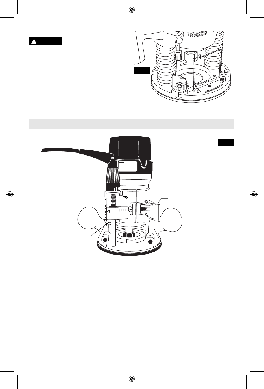
Routers
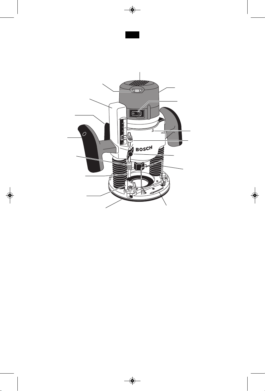
SPEED CONTROL DIAL
Models 1617EVS
& 1618EVS only
ROCKER ON\OFF
SWITCH
BASE CLAMP LEVER
ROUND
HANDLE
SUB-BASE
BIT ROTATION ARROW
AIR VENTS
FIG. 1
1617EVS
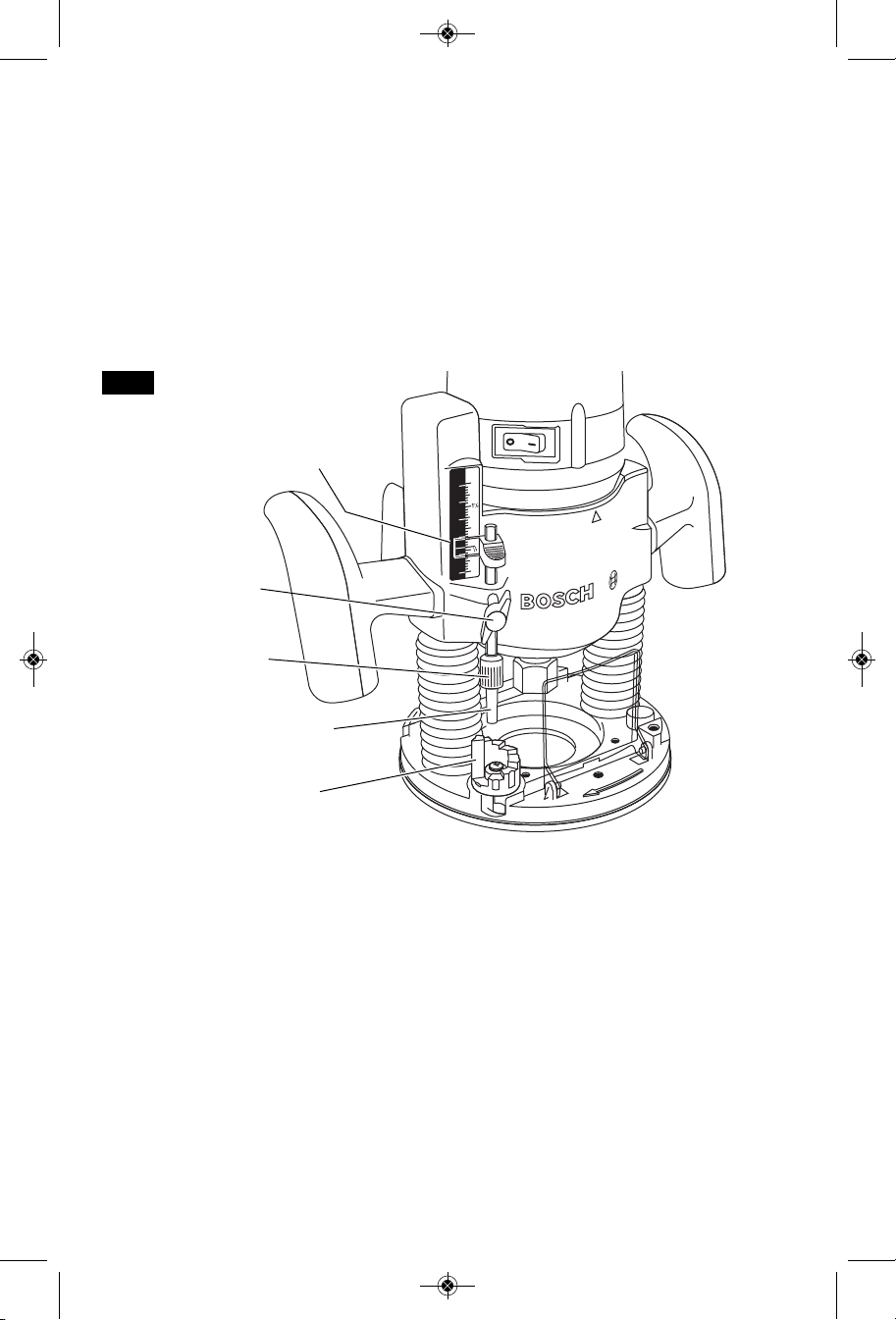
MOTOR HOUSING
MOTOR ALIGNMENT
ARROW
BASE TYPE S
CHIP DEFLECTOR
TEMPLET GUIDE
QUICK CHANGE LEVER
(Not included, available as
accessory)
SPEED CONTROL DIAL
Models 1617EVS
& 1618EVS only
POWER ON/OFF
SWITCH
BASE TYPE D
REVERSIBLE
HANDLE
BIT ROTATION ARROW
AIR VENTS
FIG. 2
1618EVS
"LOCK-ON"
BUTTON
TRIGGER
SWITCH
D-HANDLE
TEMPLET GUIDE
QUICK CHANGE LEVER
(Not included, available as accessory)
-8-
2
1
0
IN
50
40
30
20
10
0
MM
BM 2610018532 01-12:BM 2610018532 01-12.qxp 1/23/12 9:21 AM Page 9
FIG. 3
1617EVSPK
AIR VENTS
SPEED CONTROL DIAL
Model 1617EVSP only
MOTOR HOUSING
PLUNGE LOCK
LEVER
PLUNGE HANDLE
DEPTH ROD FINE
ADJUSMENT KNOB
DEPTH ROD
DEPTH STOP TURRET
BASE TYPE P
ROCKER ON\OFF SWITCH
ALIGNMENT ARROW
DEPTH INDICATOR
DEPTH ROD KNOB
CHIP DEFLECTOR
SUB-BASE
BIT ROTATION ARROW
Collet capacities 1/4", 3/8", 1/2", 8mm
NOTE: For tool specifications refer to the nameplate on your tool.
MOTOR
RA1161 fixed-base shop router base marked type "S" is designed for use with these router motors:
1617 router motor (16171)
1617EVS router motor (16176)
1618EVS router motor (16186)
RA1162 D-handle router base marked type "D" is designed only for use with these router motors:
1618EVS router motor (16186)
RA1166 plunge router base marked type "P" is designed for use with these router motors:
1617 router motor (16171)
1617EVS router motor (16176)
1618EVS router motor (16186)
-9-

BM 2610018532 01-12:BM 2610018532 01-12.qxp 1/23/12 9:21 AM Page 10
Assembly
A wide assortment of router bits with different
profiles is available separately. Use 1/2"
shank whenever possible, and only use good
quality bits.
WARNING
!
from power source before removing or
installing bits or accessories.
INSTALLING A ROUTER BIT
Place router upside down or lay router on its
side with the base resting on the bench.
Another option is to remove the motor from
the base before installing the bit.
1. Remove the chip shield (or flip up if plunge
base is attached.
2. Hold the armature shaft in place with the
shaft wrench (Fig. 4)
3. Next, use the collet wrench to loosen the
collet c huck a ss embly in cou nt erclockwise direction (viewed from under the
router).
4. Once you have verified that the bit's shank
is of the proper diameter for the collet to
be used, insert the shank of the router bit
into the collet chuck assembly as far as it
will go, then back the shank out until the
cutters are approximately 1/8" to 1/4" away
from the collet nut face.
5. With the router bit inserted and the shaft
wrench holding the armature shaft, use the
collet wrench to firmly tighten the collet
chuck assembly in a clockwise direction
(viewed from under the router). To ensure
proper gri pp in g of the route r bit and
minimize run-out, the shank of the router
bit must be inserted at least 5/8".
To prevent personal injury,
al wa ys remov e the p lu g
FIG. 4
COLLET
WRENCH
To tighten or loosen collet nut, hold both
wrenches in one hand and and squeeze
the wrenches together.
WARNING
!
base, do not use router bits greater than
2" in diameter as they will not fit through
the sub-base.
WARNING
!
opening for the bit and cutter.
CAUTION
!
without a bit.
NOTE: The bit shank and chuck should be
clean and free of dust, wood, residue and
grease before assembling.
REMOVING THE ROUTER BIT
1. Use the shaft and collet chuck wrenches
as described earlier, and turn the collet
chuck assembly in a counter-clockwise
direction.
2. Once t he c ol le t chuck assem bl y is
loosened continue to turn the collet chuck
assembly until it pulls the collet free from
its t ap er , and the route r bit can be
removed.
NOTE: The collet chuck is self-extracting; it
is NOT necessary to strike the collet chuck to
free the router bit.
When t he templet guid e
ha s been remov ed fro m
Cutter diameter must be at
least 1/4” smal le r th an
To prevent d am ag e to
tool, do not tighten collet
SHAFT
WRENCH
With the router bit removed, continue to turn
COLLET CHUCK CARE
the collet chuck counter-clockwise until it is
fr ee of the shaft . To as sure a firm gri p,
occasionally blow out the collet chuck with
compressed air, and clean the taper in the
armature assembly shaft with a tissue or fine
brush. The collet chuck is made up of two
component parts as illustrated (Fig. 5); check
to see that the collet is properly seated in the
collet chuck nut and lightly thread the collet
chuck back onto the armature shaft. Replace
worn or damaged collet chucks immediately.
FIG. 5
COLLET
COLLET
CHUCK
COLLET
NUT
-10-
BM 2610018532 01-12:BM 2610018532 01-12.qxp 1/23/12 9:21 AM Page 11
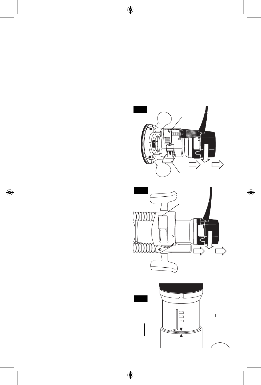
REMOVING MOTOR FROM BASE (Fig. 6)
To remove motor from non-plunge bases:
1. Hold router in horizontal position, open base
clamp lever, depress coarse adjustment
lever, and pull motor upwards until it stops.
2. Turn motor counter-clockwise, and gently
pull it free of base.
To remove motor from plunge base: (Fig. 7)
1. Hold router in horizontal position, open base
clamp lever, and pull motor upwards until it
stops.
2. Turn motor counter-clockwise, and gently
pull it free of base.
INSTALLING MOTOR IN BASE
The motor can be installed with the switch
positioned on the right or left of the base from
the operator's side (and the cord facing the
opposite side of the router). Install the motor so
that the switch is in the location you find to be
the most easily accessible from the handles.
The switch should be easier to turn "OFF" than
"ON" in case of an emergency.
To install motor in non-plunge base:
1. Release the base clamp lever.
2. Line up the arrow on the base with arrow on
the motor. (Fig. 8)
• To position switch on the right side of the
base, line up the base’s arrow with motor
housing’s arrow that is below the cord.
• To position switch on the left, line up the
base’s arrow with motor housing’s arrow
that is below the switch.
3. While pressing the coarse adjustment lever,
slide motor into base until resistance in felt.
(The base’s guide pin is now engaged into
slot on motor.)
4. Continue to press coarse adjustment lever,
and turn the motor clockwise until it stops.
5. Push the motor into the base until it reaches
the approximate desired depth.
6. Release the coarse adjustment lever and
slide the motor forward or back as needed
until the coarse adjustment system’s “catch”
springs into the coarse adjustment detent
notch.
7. Set final height position as described below
in “Operating Instructions”.
To install motor in plunge base:
1. Release the base clamp lever.
2. Line up the arrow on the base with arrow on
the motor. (Fig. 8)
• To position switch on the right side of the
base, line up the base’s arrow with arrow
on the motor housing that is below the
cord.
• To position switch on the left, line up the
base’s arrow with arrow on the motor
housing that is below the switch.
3. Slide motor into base until resistance in felt.
(The base’s guide pin is now engaged into
slot on motor.)
4. Turn the motor clockwise until it stops.
5. Push the motor into the base as far as it will
go.
6. Fasten the base clamp lever.
FIG. 6
COARSE
ADJUSTMENT
LEVER
BASE CLAMP LEVER
FIG. 7
BASE
CLAMP
LEVER
MOTOR
FIG. 8
ALIGNMENT
ARROWS
BASE
COARSE
ADJUSTMENT
NOTCHES
-11-
BM 2610018532 01-12:BM 2610018532 01-12.qxp 1/23/12 9:21 AM Page 12
CHIP DEFLECTOR
WARNING
!
deflector is not intended as a safety guard.
The chip deflectors help keep dust and chips
out of your face, it will not stop objects larger
than dust thrown from the bit.
To remov e chip shield from bases, press
inward on tabs until it releases from base and
remove. To attach, place deflector into position
as shown in (Fig. 9). Then flex s ides o f
deflector while pushing until it snaps into place.
The plunge base’s chip shield can also be
flipped out.
Al ways we ar eye
pr otectio n. Th e c hi p
FIG. 9
Operating Instructions
FIG. 10
FINE ADJUSTMENT DIAL
INDICATOR RING
CAST INDICATOR MARKS
COARSE
ADJUSTMENT
LEVER
B
Bo sch routers are designed for speed,
accuracy a nd con venience i n performing
cabinet work, routing, fluting, beading, covecutting, dove tails, etc. They will enable you to
accomplish inlay work, decorative edges and
many types of special carving.
DEPTH ADJUSTMENT
WITH FIXED BASE
Router’s RA1161 fixed base are equipped with
a true microme ter typ e fine adjustm ent
mechanism, which can be used in any position
and provides precise adjustment of the router
bit position for unmatched accuracy. When the
tool is lowered to the approximate position
de sired, this device may b e ad ju sted t o
precisely set the final bit position.
A
Your router also features three horizontal
notches on both sides of the motor housing for
coarse adjustments. The notches are spaced
1/2" apart which allows you to quickly lower or
raise the tool depth in three 1/2" increments.
(A pproximat ely 12.7 mm), by simply
depressing the coarse adjustment release
lever.
NOTE: All depth adjustments must be made
with the base clamp lever released.
1. Hold the tool in a horizontal position with the
base clamp lever facing you.
2. Open the base clamp lever to release the
motor.
BASE CLAMP LEVER
TO ADJUST DEPTH
-12-

BM 2610018532 01-12:BM 2610018532 01-12.qxp 1/23/12 9:21 AM Page 13
3. COARSE ADJUSTMENT:
To make a large depth adjustment, depress
coarse adjustment release lever and raise or
lo wer to desir ed dep th. Th ere ar e th ree
no tches in t he m otor h ousing whic h are
spaced 1/2" to facilitate this adjustment.
4. FINE DEPTH ADJUSTMENT:
To use the fine adjustment feature, turn the
fine adjustment knob clockwise to lower the
router bit or counter-clockwise to raise it.
NOTE: Be sure coarse adjustment lever is
engaged in one of the coarse adjustment
notches before making a fine adjustment.
To allow precise settings, the indicator ring is
graduated in English and Metric increments.
(Note: one full turn of fine adjustment knob =
1/16" o r approximately 1. 5 mm. The fine
adjustment mechanism has a total adjustment
range of 7/8" (23 mm). Each cast indicator
mark next to coarse adjustment lever is equal
to 1/8"
To prevent damage to tool, avoid wedging the
coarse adjustment lever against the upper A or
lower B portion of the housing as shown in
figure 10.
5. After making depth adjustments, re-clamp
the motor.
The indicator ring may be reset to zero without
moving the fine adjustment knob, to allow the
us er to begin the adj ustment fro m an y
reference point desired.
When the router is installed in a router table,
it can be adjusted with a 1/8” hex wrench, not
included with all models. (See page 21).
The RA10 02 Fi ne Adjustm en t C ontrol
Extension, an optional accessory for the non-
plunge bases, allows fine adjustment from
beyond the top of the motor housing. To
install, simply press the RA1002 into the end
of the base’s own fine adjus tment knob.
(Fig. 11)
TO CLAMP MOTOR
When final coarse and fine adjustments have
been made, fasten the base clamp lever to
secure adjustments. (If additional clamping
force i s desired: using a 10 mm wrench,
rotate clamp nut clockwise SLIGHTLY (1/8
turn or less), then test clamp. Do not overtighten.)
DEEP CUTS
For deeper cuts, make several progressively
deeper cuts by starting at one depth and
th en make several su bs equent passe s,
increasing the cutting depth with each pass.
To be certain that your depth settings are as
desired, you may want to make test cuts in
scrap material before beginning work.
FIG. 11
DEPTH ADJUSTMENT WITH PLUNGE
BASE PLUNGING ACTION
Th e pl unge fe at ure simplif ies depth
adjustments and will allow the cutting bit to
easily and accurately enter the workpiece. To
lower, push plunge lock lever to the left, apply
downward pressure until you reach desired
depth, and release pressure on lever to lock
(Fig. 12 ). The plunge lock lever is spr ing
loaded and returns automatically to the locked
position. To raise the router, push plunge lock
lever to the left, release pressure on router and
the router will automatically retract the bit from
the workpiece. It is advisable to retract the bit
whenever it is not engaged in work piece.
FIG. 12
-13-
2
1
0
IN
50
40
30
20
10
0
MM
BM 2610018532 01-12:BM 2610018532 01-12.qxp 1/23/12 9:21 AM Page 14
The depth rod and the depth stop turret are
DEPTH ROD AND TURRET
used to control cutting depth as follows;
1. With the bit installed, gently lower the motor
until the tip of the router bit just contacts the
level surface the router is sitting on. This is
the “zero” position, from which further depth
adjustments can be accurately made.
2. To set a desired depth of cut, rotate depth
stop turret until the lowest step is aligned
with the depth rod. Loosen depth indicator
kn ob an d lower the depth rod until it
contacts the lowest step of the turret. Slide
FIG. 13
DEPTH
INDICATOR
DEPTH INDICATOR
KNOB
DEPTH ROD FINE
ADJUSMENT KNOB
the depth indicator until the red line indicates
zero on the depth scale, indicating the point
at w hich the bit jus t contacts the w ork
(Fig. 13).
3. To set a desired cutting depth, slide the
depth rod up until the red depth indicator line
attains the desired cutting depth, and secure
the rod in position by firmly tightening the
depth indicator knob.
4. The desir ed dep th of cut may n ow b e
achieved by plunging the router until the
depth rod contacts the selected stop on the
turret.
DEPTH ROD
DEPTH STOP
TURRET
DEEP CUTS
For deeper cuts, make several progressively
deeper cuts by starting with the highest step on
the depth turret, and after each cut, rotate the
depth turret to progressively lower steps as
desired, until the final depth (lowest step or flat)
is reached. Steps progress by 1/8” increments.
To be certain that your depth settings are as
desired, you may want to make test cuts in
scrap material before beginning work.
FINE ADJUSTMENT
The RA1166 plunge base is equipped with a
fine adjustment system that allows you to
micro adjust the plunge depth of the router bit
for superior routing accuracy.
Ea ch comple te revoluti on of th e fine
adjustment stop adjusts the plunging depth by
1/32”, and each of the four indicator marks on
the knob represents 1/128”. One of the four
tick marks is larger than the other to indicate a
complete revolution. A reference indicator line
is built in to the depth rod.
To use the fine adjustment knob, once the
depth rod and turret have been set, check the
final depth setting and fine-adjust as follows:
To micro-increase the plunge depth, raise the
fine adjustment stop by turning it counterclockwise by the desired amount.
To micro-reduce the plunge depth, lower the
fine adjustment stop by turning it clockwise by
the desired amount.
-14-

BM 2610018532 01-12:BM 2610018532 01-12.qxp 1/23/12 9:21 AM Page 15
Notes:
• When micro-adjusting the plunge depth, it is
mo re conv enient t o mo ve th e fi ne
adjustme nt stop up than down. Before
setting the depth rod and turret, make sure
the fine adjustment stop has been turned
se veral revo lutions do wn from its top
position so that it can be adjusted upward.
• The fine adjustment stop cannot be use to
reduce the plunge depth when the depth rod
is already touching the depth stop turret.
ROCKER “ON/OFF” SWITCH
Your tool can be turned “ON” or “OFF” by the
rocker switch located on the motor housing.
One side of the switch is marked “I” for “ON“,
and the other side of switch is marked “O” for
“OFF“. Also the edge of switch displays red
when switch is in the “ON“ position.
TO TURN THE TOOL “ON”: Push the side of
the switch marked “I”.
TO TURN THE TOOL “OFF”: Push the side
of the switch marked “O”.
Always hold the router off the work when
turning the switch on or off. Contact the work
with the router after the router has reached full
speed, and remove it from the work before
turning the switch off. Operating in this manner
will prolong switch and motor life and will
greatly increase the quality of your work (Fig. 1).
ROCKER POWER "ON-OFF" WITH
TRIGGER SWITCH AND "LOCK-
The power is switched "ON" by the rocker
switch located on the top of the motor housing
as described above. Now your tool can be
tu rned "ON" or "OFF " by squ eezing or
releasing the trigger. Your tool is also equipped
with “Lock-ON” button located just above the
trigger that allows continuous operation without
holding the trigger (Fig. 2).
TO LOCK SWITCH ON: Squeeze trigger,
depress button and release trigger.
TO UNLOCK THE SWITCH: Squeeze trigger
and release it without depressing the “LockON” button.
WARNING
!
depressed, the trigger cannot be released.
On model 1617 hold the tool with both hands
while starting the tool, since torque from the
motor can cause the tool to twist.
ON"BUTTON
(Model 1618EVS only)
If the “Lock-ON” button is
co ntinuou sl y be ing
The router must be raised before such an
adjustment can be made.
• Also available is an alternative turret that
has an adjustable step which uses an M4
sc rew fo r the ad ju stable step. Th e
adjustable step makes it possible to make
multiple-pass applications without having to
make a fine depth adjustment even when
the total cutting depth is not a multiple of
1/8".
SOFT START FEATURE
(Models 1617EVS & 1618EVS only)
Electronic feedback control minimizes torque
twist customary in larger routers by limiting the
speed at which motor starts.
ELECTRONIC VARIABLE
(Models 1617EVS & 1618EVS only)
The electronic speed control feature allows
motor speed to be matched to cutter size and
ma terial hardnes s fo r i mp roved finish ,
extended bit life, and higher performance.
Speed c hanges are achieved by rotating
Control Dial RIGHT to increase speed, LEFT
to decrease as indicated on housing (Fig. 1).
Speed may be changed while tool is on. The
reference numbers on the dial facilitate resetting control to desired speed.
The speed chart indicates the relationship
between settings and application, exact settings
are determined by operator experience and
preference. The bit manufacturer may also
have a speed recommendation.
DIAL
SETTING RPM APPLICATION
1 8,000
2 13,500
3 16,500
4 20,000
5 21,500
6 25,000
CONSTANT RESPONSE™ CIRCUITRY
(Models 1617EVS & 1618EVS only)
The router's Constant Response™ Circuitry
monitors and adjusts power to maintain the
desired RPM for consistent performance and
control.
SPEED CONTROL
Nonferrous metals,
larger diameter bits
}
and cutters
Softwoods, plastics,
counter tops, smaller
}
diameter bits and
cutters
-15-

BM 2610018532 01-12:BM 2610018532 01-12.qxp 1/23/12 9:21 AM Page 16
As seen from the top of the router, the bit turns
FEEDING THE ROUTER
cl ockwise an d the cuttin g e dges face
accordingly. Therefore, the most efficient cut is
made by feeding the router so that the bit turns
into the work, not away. Figure 14 shows
proper feed for various cuts. How fast you feed
depends on the hardness of the material and
the size of the cut. For some materials, it is
best to make several cuts of increasing depth.
FIG. 14
START
HERE
WORK
BIT
DIRECTION OF
ROUTER FEED
If the router is hard to control, heats up, runs
ve ry sl owly or le aves an imperfect cu t,
consider these causes:
1. Wrong direction of feed — hard to control.
2. Feeding too fast — overloads motor.
3. Dull bit — overloads motor.
4. Cut is too large for one pass — overloads
motor.
5. Feeding too slow — leaves friction burns on
work.
Feed smoothly and steadily (do not force). You
will soon learn how the router sounds and feels
when it is working best.
RATE OF FEED
When routing or doing related work in wood
and plastics, the best finishes will result if the
depth of cut and feed rate are regulated to
keep the motor operating at high speed. Feed
the router at a moderate rate. Soft materials
require a faster feed rate than hard materials.
The router may stall if improperly used or
overloaded. Reduce the feed rate to prevent
possible damage to the tool. Always be sure
the collet chuck is tightened securely before
use. Always use router bits with the shortest
cu tting len gth necessa ry t o pr oduce the
desired cut. This will minimize router bit run-out
and chatter.
The router can be guided through the work in
GUIDING THE ROUTER
any of several ways. The method you use
depends, of course, on the demands of the
particular job and on convenience.
For routing operations such as grooving or
dadoing, it is often necessary to guide the tool
in a line parallel t o a st raight edg e. One
method of obtaining a straight cut is to securely
clamp a board or other straightedge to the
work surface, and guide the edge of the router
sub-base along this path (Fig. 15).
FIG. 15
SECURELY CLAMP
BOARD GUIDE
-16-
FEED
DIRECTION
BOARD GUIDE

BM 2610018532 01-12:BM 2610018532 01-12.qxp 1/23/12 9:21 AM Page 17
ROUTER DUST COLLECTION
There are three optional dust extraction hood
accessories. Each dust extraction hood is
sized to accept 35mm vacuum hoses. Each
accessory pack includes the VAC002 adapter
that will connect the hood to 1-1/4” and 1-1/2”
vacuum hoses. An adapter to connect the
ho od to 2-1/2" hoses is als o availa ble
separately.
ROUTER DUST COLLECTION FOR
This dust extraction hood is designed for use
the plunge base (RA1166) when routing is
done in the middle of the workpiece, such as
when creating slots or routing patterns for
inlays. If you have a shop vacuum system, you
ca n att ach the dust extra ct ion hood fo r
im proved visibi li ty, ac curacy and u tility,
particularly in freehand routing.
To attach, position as shown and secure
ad apter to base with th e thum bscrews
provided (Fig. 16).
DUST EXTRACTION HOOD FOR
!
WARNING
manual for use of these accessories.
Do not reach in area of the bit while the
router is ON or plugged in.
CAUTION
!
extraction hood at the same time as any
other dust extraction hood.
This dust extraction hood is designed for use
with Bosch routers 1617, 1617EVS, 1618EVS
and their fixed bases when the routing is done
in the middle of the workpiece, such as when
creating slots or routing out patterns for inlays.
To attach the hood to the router base, slide
the hood into the backside of the router base
around the router’s depth adjustment rod with
the hood’s rounded corners facing up (Fig. 17
& 18). Se curely t ighten t he two knurled
thumbscrews.
USING THE HOOD FOR BACKSIDE OF
For maximum dust collection effectiveness,
make sure the router’s chip shield is in place.
PLUNGE BASE
BACKSIDE OF FIXED BASE
Read and understand these
in st ru ct ions and tool
To avoid entangling hoses,
do not u se th is dust
FIXED BASE
FIG. 16
DUST EXTRACTION HOOD
(Optional Accessory)
The dust extraction hood can also be installed
with the hose outlet facing the front of the tool.
If the templet guide adapter is installed, it will
need to be reversed or removed to allow the
release lever to fit under the dust hood.
M4 THUMB
SCREWS
FIG. 17
M5 SCREW
DUST
EXTRACTION
HOOD
ROUTER
BASE
FIG. 18
-17-
BM 2610018532 01-12:BM 2610018532 01-12.qxp 1/23/12 9:21 AM Page 18
EDGEFORMING DUST
EXTRACTION HOOD
!
WARNING
Do not reach in area of the
bit while the router is ON or
plugged in. To avoid entangling hoses, do
not use this dust extraction hood at the
same time as any other dust extraction
hood.
This dust extraction hood (optional accessory)
is used for dust collection when edge-forming
(Fig. 19).
ATTACHING DUST EXTRACTION HOOD
You can attach the edge-forming hood in
several places according to your needs or
preferences. This hood is attached using two
of the screw holes on the router base that are
used to attach the router’s sub-base. Choose
the desired location for the hood. Loosen and
take out the two screws from the router base
and attach the dust extraction hood — over the
router’s sub-base — using the screws provided
with the hood. Securely tighten the screws.
(Figures 20 & 21).
FIG. 21
OTHER BASES
FIG. 19
ROUTER
SUB-BASE
WORKPIECE
EDGE
DUST
EXTRACTION
HOOD
M4 x 16mm
SCREW
FIG. 20
PLUNGE BASE
M4 x 16mm
SUB-BASE
SCREW
M4 x 16mm
SCREW
DUST
EXTRACTION
HOOD
DUST
EXTRACTION
HOOD
M4 x 16mm
SCREW
-18-
BM 2610018532 01-12:BM 2610018532 01-12.qxp 1/23/12 9:21 AM Page 19
DELUXE ROUTER GUIDE
(Not included, available as accessory)
The Bosch deluxe router guide is an optional
accessory that will guide the router parallel to a
straight edge or allow you to create circles and
arcs.
The deluxe router guide is supplied with two
rods and screws to fasten the guide (Fig. 22).
In addition, it features a fine adjustment knob
and indicator for accurately positioning the
edge guide relative to the bit. With the guide
installed and adjusted, the router should be fed
FIG. 22
BASE
CUT
DESIRED
WIDTH
M6 WING
SCREW
WORKPIECE
normally, keeping the guide in contact with the
edge of the workpiece at all times. The deluxe
router guide may also be positioned directly
under the router base for operations where a
cut is needed close to or at the edge of the work.
The deluxe ro uter guid e in cludes a dust
extraction hood and the VAC002 vacuum hose
adapter.
For complete instructions on installation and
operation, please refer to the instructions
which are included with this accessory.
FEED
DIRECTION
M6 WING SCREW
FINE
ADJUSTMENT
INDICATOR
ROUTER
GUIDE
FINE
ADJUSTMENT
KNOB
RODS
This router can also be used with the optional
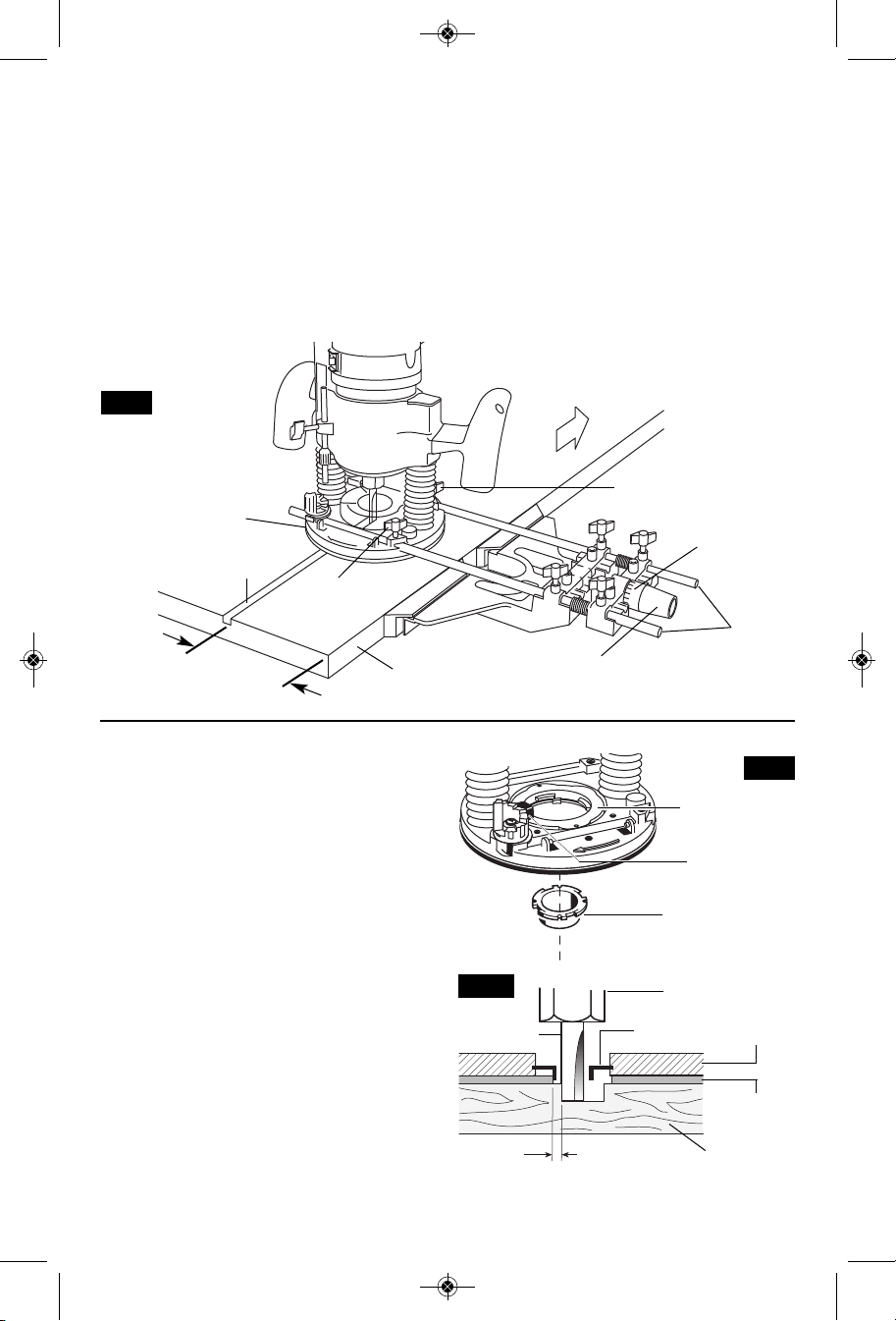
TEMPLET GUIDES
Bosch-exclusive quick-change templet guide
system, which firmly grips the guides with a
sp ring-load ed ri ng. Unl ik e conve ntional
threaded templet guides, there is no threaded
ring that can come loose while routing.
Templet guides are used with a number of
special accessories, such as hinge templets,
which are listed in your BOSCH catalog. In
addition, special templets are easily prepared
for cu tt ing re pe ated p at te rns, s pe cial
designs, inlays, and other applications. A
templet pattern may be made of plywood,
hardboard, metal or even plastic, and the
design can be cut with a router, jigsaw, or
other suitable cutting tool. Remember that
the p at te rn will h av e to b e m ad e to
compensate for the distance between the
router bit and the templet guide (the “offset”),
as the final workpiece will differ in size from
the templet pattern by that amount, due to
the bit position (Fig. 24).
FIG. 24
ROUTER BIT
-19-
OFFSET
TEMPLET GUIDE
ADAPTER
TEMPLET GUIDE
RELEASE LEVER
TEMPLET GUIDE
(optional accessory)
COLLET CHUCK
TEMPLET
GUIDE
WORKPIECE
FIG. 23
ROUTER
SUB-BASE
TEMPLET
PATTERN

D D
B
A
B
A
B
A
C
C
D
BM 2610018532 01-12:BM 2610018532 01-12.qxp 1/23/12 9:21 AM Page 20
INSTALLING TEMPLET GUIDE ADAPTER
(Not included, available as accessory)
Place templet guide adapter over the holes in
the center of the sub-base, and align the two
threaded holes in the bottom of adapter with
the countersunk holes in sub-base. Fasten
adapter with the screws provided. Note that
the adapter is reversible, so the release lever
may be positioned as desired. (Fig. 25)
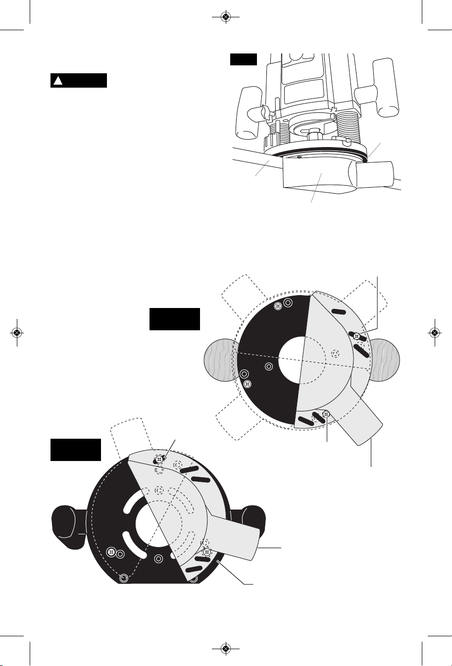
CENTERING THE SUB-BASE OR
TEMPLET GUIDES
Your router features the Bosch “Precision
Centering Design”. Its sub-base is precisely
centered at the factory. This positions the bit at
th e ce nter o f th e sub- base and o ptional
templet guides.
Precision centering allows you to use the edge
of the subbase or templet guides to closely
follow jigs such as straight guides, templets,
and dovetail fixtures without worrying about bit
walk-off from the intended cut line for any
reason, including the orientation of the router’s
handles relative to the jig.
To quickly re-center the sub-base, attach the
sub-base using the set of flathead screws
(included) and the countersunk screw holes in
the sub-base. (Flathead screws have the
FIG. 25
TEMPLET GUIDE
ADAPTER
(optional accessory)
MOUNTING SCREWS
tapered heads.) The flathead screws and
countersunk holes will pull the sub-base into a
position that is very close to centered.
To most precisely re-center the sub-base or
templet guides, attach the sub-base using the
optional Bosch RA1151 Centering Device.
Follow steps 1-8 (Fig. 26 & 27).
1. If a templet guide is to be centered, Install
the templet guide adapter and template
guide (optional attachments) as described
elsewhere in this manual.
2. Position the sub-base so that its pan-head
screw holes are over the matching set of
threaded holes in the base.
3. Insert the pan-head screws through the subbase and tighten them until they are snug,
but still allow the sub-base to move.
CENTERING CONE
(optional accessory)
FIG. 26
PLUNGE BASE
CENTERING SHAFT
(optional accessory)
TEMPLET GUIDE
(optional accessory)
CENTERING SHAFT
(optional accessory)
CENTERING SHAFT
(optional accessory)
FIG. 27
OTHER BASES
A=M4 COUNTERSUNK SCREW
HOLES
B=M4 PAN-HEAD SCREW HOLES
SUB-BASE
-20-
C=TEMPLET GUIDE ADAPTER
SCREW HOLES
D=HOLES FOR ATTACHING
ROUTER TO ROUTER TABLE
MOUNTING PLATE
(Under sub-base on
non-plunge bases)
BM 2610018532 01-12:BM 2610018532 01-12.qxp 1/23/12 9:21 AM Page 21
4. Prepare the Centering Device:
• Us e na rrow end of steel s haft when
inserting into 1/4” collet, wider end of cone
when inserting into 1/2” collet.
• When centering subbase or templet guide
that has opening of more than ½”, slide
the wide plastic sleeve over the steel
shaft.
5. Slide centering sleeve through the sub-base
or templet guide and into collet. Tighten
MAXIMUM BIT/CUTTER SIZE FOR
TEMPLET GUIDES
When using a templet guide, use only router
bit with cutters that are 1/16” less than the
internal diameter of the templet guide, such as
in the table below.
collet nut with fingers to put slight grip on
centering cone.
6. Lightly press centering sleeve into sub-base
or templet guide to center.
7. Tighten the pan-head screws. Remo ve
centering sleeve.
8. The precision centering of the sub-base or
templet guide is complete.
CENTERING CONE – Used when centering
the subbase itself or wide templet guides.
USE WITH THREADED
TEMPLET GUIDES
Also available as an optional accessory is an
additional adapter, the RA1100, that allows
use of conventional threaded templet guides
with the Bosch quick-release system.
Bosch Bushing External Internal Max
Templet Depth Diameter Diameter Bit/Cutter
Guide Diameter
ABB
RA1101 3/16” 5/16” 1/4” 3/16”
RA1103 9/64” 5/16” 17/64” 13/64”
RA1105 9/64” 7/16” 3/8” 5/16”
RA1107 5/16” 7/16” 3/8” 5/16”
RA1109 7/16” 1/2” 13/32” 11/32”
RA1111 3/16” 5/8” 17/32” 15/32”
RA1113 1/2” 5/8” 17/32” 15/32”
RA1115 3/16” 3/4” 21/32” 19/32”
RA1117 31/64” 13/16” 5/8” 9/16”
RA1119 31/64” 1” 25/32” 21/32”
RA1121 7/16” 1-3/8” 1-19/64” 1-15/64”
Your router can also be used in a router table.
USE IN ROUTER TABLE
The RA1161 fixed base is designed to allow
easy depth adjustment in a table. The RA1162
"D" D-Handle base will not fit in most router
tables.
CAUTION
!
The RA1166 Plunge Base is
not recommended for use
in a router table. Damage to plunge router
base may occur.
To eliminate the hassle of ins talling your
router’s own base on the router table and later
having to convert it back for non-table use,
Bosch offers the optional RA1165 Undertable
Router Base (Fig. 28). The RA1165 base is
designed to be permanently attached your
router table, leaving your other router bases
ready for non-table use. The motor can be
quickly moved from base to base — without
any tools!
FIG. 28
10-24 Screw
Mounting
Plate
Quick-release
clamp lever
and depth
adjustment
controls should
face the front of the router table
-21-
Hex
Wrench
Hole for Hex
Wrench
Shown after
subbase has
been removed

BM 2610018532 01-12:BM 2610018532 01-12.qxp 1/23/12 9:21 AM Page 22
The undertable base accessory includes the
screws needed to fasten the base to a router
table m oun ting plate, as well as a T-hex
wrench for above-table depth adjustment.
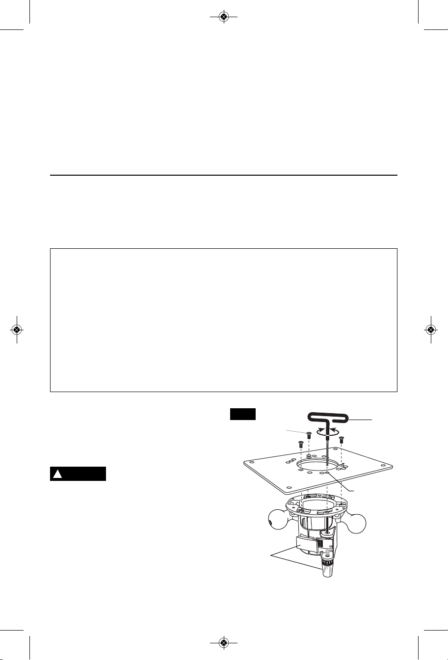
ATTACHING BASE TO
MOUNTING PLATE
At tach t he RA116 1 to the ro uter t ab le’s
mounting plate using either or both sets of
enclosed mounting screws.
The base has two sets of threaded holes for
mounting the base:
• Three 10-24 holes in industry-standard
3-hole pattern.
• Four M4 holes in Bosch 4-hole pattern.
Mounting screws required for the RA1161:
(not included with all models).
• Three 10-24 screws.
• Four M4 screws.
The length will depend on the thickness of
your router table or router table mounting
plate.
If your router table mounting plate does not
have countersunk holes in either of those
patterns, you will need to determine the hole
locations, drill and countersink them, also
locate an d dr ill a hole for the over -table
adjustment wrench.
CONNECT THE ROUTER AND THE
ROUTER TABLE SWITCH
To prepare for use of the switch,
1. Make sure the router switch and the router
table switch are both turned off.
2. Plug the router table switch cord to wall
outlet.
3. Plug the router into the "pigtail" socket on
the router table switch.
4. Lock router switch on: squeeze trigger,
depress lock-on button, and release trigger.
5. Use the router table switch to start and stop
the router.
DEPTH ADJUSTMENT (See page 12-13)
FEEDING THE WORKPIECE
ON A ROUTER TABLE
Always use your router table's fence or starter
pin and the appropriate guard and follow the
router table's instruction manual. ALWAYS
feed the workpiece from right to left across the
front of the bit. On Bosch router tables, the
correct feed direction is also shown on fence
housing and on the featherboards, when they
have been properly installed. (Fig. 29)
Whenever possible, when using the fence,
use a push stick to push the workpiece ,
especially when working with narrow pieces.
For complete instructions on operation of a
router in a router table, please refer to the
instructions that come with the router table.
TOP VIEW
NOTE: For clarity, guard and featherboard
removed from drawing.
FIG. 29
DIRECTION
OF FEED
FENCE FACE
BIT
BEARING
FENCE FACE
WORKPIECE
-22-

BM 2610018532 01-12:BM 2610018532 01-12.qxp 1/23/12 9:21 AM Page 23
Maintenance
Service
WARNING
!
per so n nel may result in misplacing of
internal wires and com ponen ts which
could cause serious hazard. We recommend
that all tool service be performed by a Bosch
Factory Service Center or Autho rized Bosch
Service Station.
Your Bosch tool has been properly lubricated
and is ready to use. It is recommended that
tools with gears be regreased with a special
gear lubricant at every brush change.
The brushes and commutator in your tool have
be en engineer ed for many hours of
de pendable s ervice. To ma intain p ea k
efficiency of the motor, we recommend every
two to six months the brush es be examined.
Only genuine Bosch replace ment brushes
specially designed for your tool should be
used.
After about 300-400 hours of operation, or at
every second brush change, the bearings
Pr event ive maintenance
performed by unauthorized
TOOL LUBRICATION
CARBON BRUSHES
BEARINGS
should be replaced at Bosch Factory Service
Center or Au thorized Bosch Service Station.
Bearings which become noisy (due to heavy
load or very abrasive material cut ting) should
be replaced at once to avoid overheating or
motor failure.
Cleaning
WARNING
!
th e power supply before cleani ng or
performing any main tenance. The tool may
be cleaned most effectively with compressed
dry air. Always wear safety gog gles when
cleaning tools with compressed air.
Ventilation openings and switch levers must be
kept clean and free of foreign matter. Do not
at tempt to clean by inserting pointed objects
through openings.
CAUTION
!
plastic parts. Some of these are: gasoline,
carbon tetrachlo ride, chlo rinated cleaning
solvents, ammonia and house hold detergents
that contain ammonia.
To avoid accidents always
dis connect the tool from
Ce rtain cl eaning age nts
an d so l ve nts damage
Extension Cords
WARNING
!
adequate size conductors that is capable
of carrying the current necessary for your
tool mu st be used . This wi ll pr ev ent
excessive volt age drop , loss of power or
overheating. Grounded tools must use 3-wire
extension cords that have 3-prong plugs and
receptacles.
NOTE: The smaller the gauge number, the
heav i er the cord.
If an ex te nsion cord is
necessa ry , a co rd with
RECOMMENDED SIZES OF EXTENSION CORDS
120 VOLT ALTERNATING CURRENT TOOLS
Tool’s
Ampere
Rating
3-6
6-8
8-10
10-12
12-16
Cord Size in A.W.G.
Cord Length in Feet Cord Length in Meters
25 50 100 150 15 30 60 120
18 16 16 14 0.75 0.75 1.5 2.5
18 16 14 12 0.75 1.0 2.5 4.0
18 16 14 12 0.75 1.0 2.5 4.0
16 16 14 12 1.0 2.5 4.0 —
14 12 —— ————
Wire Sizes in mm
-23-
2

BM 2610018532 01-12:BM 2610018532 01-12.qxp 1/23/12 9:21 AM Page 24
Accessories
1/4” Collet Chuck *
1/2” Collet Chuck *
16 mm Shaft Wrench *
24 mm Collet Nut Wrench *
T-Hex Wrench (Std with 1617EVS and
1617EVSPK only)
3/8” Collet Chuck **
8 mm Collet Chuck **
Deluxe Router Guide **
Centering Device **
Carry Case (Std with 1617K, 1617EVSK,
1617EVSPK only)
Dust Extraction Hoods **
Edge-Forming Dust Extraction Hood **
Fine Adjustment Control Extension **
Undertable Base with Fine Adjustment
Control Extension **
Router Tables **
Quick-Release Templet Guides **
Templet Guide Adapter **
Adapter for Standard-Style Templet Guides **
Adjustable Depth Stop Turret **
(*= standard equipment)
(**= optional accessories)
-24-

BM 2610018532 01-12:BM 2610018532 01-12.qxp 1/23/12 9:21 AM Page 25
Avertissements généraux concernant la sécurité des outils électroportatifs
!
AVERTISSEMENT
choc électrique, d'incendie et/ou de blessures corporelles graves.
Veuillez lire tous les avertissements et toutes les consignes de sécurité. Si l'on
n'observe pas ces avertissements et ces consignes de sécurité, il existe un risque de
CONSERVEZ TOUS LES AVERTISSEMENTS ET TOUTES LES CONSIGNES
DE SÉCURITÉ POUR RÉFÉRENCE FUTURE.
Dans les avertissements, le terme « outil électroportatif » se rapporte à votre outil branché sur le secteur (avec fil) ou
à votre outil alimenté par piles (sans fil).
Sécurité du lieu de travail
Maintenez le lieu de travail propre et bien éclairé.
Les risques d’accident sont plus élevés quand on
travaille dans un endroit encombré ou sombre.
N’utilisez pas d’outils électroportatifs dans des
atmosphères explosives, comme par exemple en
présence de gaz, de poussières ou de liquides
inflammables. Les outils électroportatifs produisent
des étincelles qui risquent d’enflammer les poussières
ou les vapeurs.
Éloignez les enfants et les visiteurs quand vous vous
servez d’un outil électroportatif. Vous risquez une
perte de contrôle si on vous distrait.
Sécurité électrique
Les fiches des outils électroportatifs doivent
correspondre à la prise. Il ne faut absolument jamais
modifier la fiche. N’utilisez pas d’adaptateur de prise
avec des outils électroportatifs munis d’une fiche de
terre. Le risque de choc électrique est moindre si on
utilise une fiche non modifiée sur une prise qui lui
correspond.
Évitez tout contact du corps avec des surfaces reliées
à la terre tels que tuyaux, radiateurs, gazinières ou
réfrigérateurs. Le risque de choc électrique augmente
si votre corps est relié à la terre.
N’exposez pas les outils électroportatifs à la pluie ou
à l’humidité. Si de l’eau pénètre dans un outil
électroportatif, le risque de choc électrique augmente.
Ne maltraitez pas le cordon. Ne vous en servez
jamais pour transporter l’outil électroportatif, pour le
tirer ou pour le débrancher. Éloignez le cordon de la
chaleur, des huiles, des arêtes coupantes ou des
pièces mobiles. Les cordons abîmés ou emmêlés
augmentent les risques de choc électrique.
Si vous utilisez un outil électroportatif à l’extérieur,
employez une rallonge conçue pour l’extérieur. Ces
rallonges sont faites pour l’extérieur et réduisent le
risque de choc électrique.
S'il est absolument nécessaire d'utiliser l'outil
électroportatif dans un endroit humide, utilisez une
alimentation protégée par un disjoncteur de fuite de
terre (GFCI). L'utilisation d'un disjoncteur GFCI réduit
les risques de choc électrique.
Restez concentré, faites attention à ce que vous
faites, et servez-vous de votre bon sens lorsque vous
utilisez un outil électroportatif. N'employez pas
d’outils électroportatifs quand vous êtes fatigué ou
sous l’emprise de drogues, d’alcool ou de
médicaments. Quand on utilise des outils
électroportatifs, il suffit d’un moment d’inattention pour
causer des blessures corporelles graves.
Utilisez des équipements de sécurité personnelle.
Portez toujours une protection oculaire. Le port
d'équipements de sécurité tels que des masques
antipoussières, des chaussures de sécurité
antidérapantes, des casques de chantier et des
protecteurs d'oreilles dans des conditions appropriées
réduira le risque de blessure corporelle.
Évitez les démarrages intempestifs. Assurez-vous que
l'interrupteur est dans la position arrêt (Off) avant de
brancher l'outil dans une prise de courant et/ou un
bloc-piles, de le ramasser ou de le transporter. Le
transport d'un outil électroportatif avec le doigt sur la
gâchette ou le branchement de cet outil quand
l'interrupteur est en position de marche (ON) est une
invite aux accidents.
Enlevez toutes les clés de réglage avant de mettre
l’outil électroportatif en marche. Si on laisse une clé
sur une pièce tournante de l’outil électroportatif, il y a
risque de blessure corporelle.
Ne vous penchez pas. Conservez toujours une bonne
assise et un bon équilibre. Ceci vous permettra de
mieux maîtriser l’outil électroportatif dans des situations
inattendues.
Habillez-vous de manière appropriée. Ne portez pas
de vêtements amples ou de bijoux. Attachez les
cheveux longs. N’approchez pas les cheveux, les
vêtements ou les gants des pièces en mouvement.
Les vêtements amples, les bijoux ou les cheveux longs
risquent d’être happés par les pièces en mouvement.
Si l’outil est muni de dispositifs permettant le
raccordement d’un système d’aspiration et de
collecte des poussières, assurez-vous que ces
dispositifs sont raccordés et utilisés correctement.
L'utilisation d'un dépoussiéreur peut réduire les
dangers associés à l'accumulation de poussière.
Sécurité personnelle
-25-

BM 2610018532 01-12:BM 2610018532 01-12.qxp 1/23/12 9:21 AM Page 26
Utilisation et entretien des outils
électroportatifs
Ne forcez pas sur l’outil électroportatif. Utilisez l’outil
électroportatif qui convient à la tâche à effectuer.
L’outil qui convient à la tâche fait un meilleur travail et
est plus sûr à la vitesse pour lequel il a été conçu.
Ne vous servez pas de l’outil électroportatif si son
interrupteur ne parvient pas à le mettre en marche ou
à l’arrêter. Tout outil électroportatif qui ne peut pas
être commandé par son interrupteur est dangereux et
doit être réparé.
Débranchez la fiche de la prise ou enlevez le bloc-pile
de l’outil électroportatif avant tout réglage,
changement d’accessoires ou avant de ranger l’outil
électroportatif. De telles mesures de sécurité
préventive réduisent le risque de démarrage intempestif
de l’outil électroportatif.
Rangez les outils électroportatifs dont vous ne vous
servez pas hors de portée des enfants et ne permettez
pas à des personnes qui ne connaissent pas l’outil
électroportatif ou qui ignorent ces consignes de s’en
servir. Les outils électroportatifs sont dangereux dans
les mains d’utilisateurs inexpérimentés.
Entretenez les outils électroportatifs. Vérifiez que les
pièces mobiles sont alignées correctement et ne
Règles de sécurité concernant les toupies
coincent pas. Vérifiez qu’il n’y a pas de pièces
cassées ou d’autre circonstance qui risquent
d’affecter le fonctionnement de l’outil électroportatif.
Si l’outil est abîmé, faites-le réparer avant de
l’utiliser. De nombreux accidents sont causés par des
outils électroportatifs mal entretenus.
Maintenez les outils coupants affûtés et propres. Les
outils coupants entretenus correctement et dotés de
bords tranchants affûtés sont moins susceptibles de
coincer et sont plus faciles à maîtriser.
Utilisez l'outil électroportatif, les accessoires et les
embouts d'outil, etc. conformément à ces
instructions, en tenant compte des conditions de
travail et des travaux à réaliser. L'emploi d’outils
électroportatifs pour des tâches différentes de celles
pour lesquelles ils ont été prévus peut résulter en une
situation dangereuse.
Entretien
Faites réparer votre outil électroportatif par un agent
de service qualifié n’utilisant que des pièces de
rechange identiques. Ceci assure que la sécurité de
l’outil électroportatif est préservée.
Tenez l’outil électroportatif par ses surfaces de
préhension isolées parce que l’accessoire de coupe
risque d’entrer en contact avec un fil caché. Tout
contact de l’accessoire de coupe avec un fil sous
tension risque de mettre aussi sous tension les parties
métalliques exposées de l’outil électroportatif, ce qui
pourrait causer un choc électrique pour l’opérateur.
Utilisez des brides ou d’autres moyens pratiques de
brider ou de supporter la pièce sur une plate-forme
stable. Tenir la pièce à la main ou contre le corps la
rend instable et risque de résulter en une perte de
contrôle.
Il ne faut pas percer, assujettir ou casser des murs
ou d'autres structures sans visibilité à l'intérieur
desquels des fils électriques peuvent se trouver. S'il
n'est pas possible d'éviter une telle situation,
déconnectez tous les fusibles ou disjoncteurs des
circuits alimentant ce lieu de travail.
Assurez-vous toujours que la surface de travail est
exempte de clous et autres objets étrangers. La coupe
dans un clou peut faire sauter la lame et l'outil, et ainsi
abîmer la lame.
Ne tenez jamais le matériau d'une main et l'outil de
l'autre lorsque vous en faites usage. Ne placez jamais
les mains sous la surface de coupe ou à proximité de
celle-ci. Il est plus sûr de cramponner le matériau et de
guider l'outil des deux mains.
Ne posez jamais le matériau sur des surfaces dures
telles que le béton, la pierre, etc. ... La lame de coupe
en saillie peut faire sauter l'outil.
Portez toujours des lunettes de sécurité et un masque
anti-poussières. N'utilisez l'outil qu'à un endroit bien
aéré. L'utilisation de dispositifs de sécurité personnelle
et le travail dans un environnement sûr réduisent les
risques de blessures.
Après avoir changé les lames ou effectué quelque
réglage que ce soit, assurez-vous que l'écrou de la
douille et tout autre dispositif de réglage sont bien
serrés. Un dispositif de réglage lâche peut bouger
soudainement et causer ainsi une perte de contrôle avec
projection violente des composants en rotation.
Ne mettez jamais l'outil en marche alors que la lame
est enfoncée dans le matériau. Le tranchant de la lame
peut se coincer dans le matériau et vous faire perdre le
contrôle du couteau.
Tenez toujours l'outil des deux mains durant la mise
en marche. Le couple de réaction du moteur peut faire
tordre l'outil.
Le sens d'introduction de la lame dans le matériau
est très important, et il est lié au sens d'introduction
de la lame. Lorsque vous regardez l'outil depuis le
dessus, la lame tourne en sens horaire. Le sens
d'introduction du couteau doit être anti-horaire.
-26-

BM 2610018532 01-12:BM 2610018532 01-12.qxp 1/23/12 9:21 AM Page 27
REMARQUE : Les coupes intérieures et extérieures
nécessiteront des sens de déplacement différents référez-vous à la section consacrée au sens de
déplacement de la toupie. Si l'outil est introduit dans le
mauvais sens, le tranchant de la lame peut sortir du
matériau et tirer l'outil dans le sens de cette
introduction.
N'utilisez jamais de lames émoussées ou abîmées.
Les lames affilées doivent être maniées
soigneusement. Les mèches abîmées peuvent se
rompre brusquement durant l'usage. Les lames
émoussées nécessitent plus de force pour pousser
l'outil, causant éventuellement un bris de la lame.
Avertissements supplémentaires concernant la sécurité
L’emploi d’un GFCI et de dispositifs de protection
personnelle tels que gants et chaussures d’électricien en
caoutchouc améliorent votre sécurité personnelle.
N’utilisez pas un outil conçu uniquement pour le C.A.
sur une alimentation en C.C. Même si l’outil semble
fonctionner, les composants électriques d’un outil prévu
pour le C.A. tomberont probablement en panne et
risquent de créer un danger pour l’utilisateur.
Maintenez les poignées sèches et exemptes d’huile et
de graisse. On ne pas maîtriser un outil électroportatif
en toute sécurité quand on a les mains glissantes.
Utilisez des brides ou d’autres moyens pratiques de
brider ou de supporter la pièce sur une plate-forme
stable. Tenir la pièce à la main ou contre le corps est
instable et risque de résulter en une perte de contrôle.
Créez un agenda d’entretien périodique pour votre
outil. Quand vous nettoyez un outil, faites attention
de n’en démonter aucune pièce car il est toujours
possible de mal remonter ou de pincer les fils
internes ou de remonter incorrectement les ressorts
de rappel des capots de protection. Certains agents
de nettoyage tels que l’essence, le tétrachlorure de
carbone, l’ammoniaque, etc. risquent d’abîmer les
plastiques.
Ne touchez jamais la lame durant ou immédiatement
après l'usage. Après usage, la lame est trop chaude
pour être touchée à main nue.
Ne posez jamais l'outil avant que le moteur ne se soit
arrêté complètement. La lame en rotation peut saisir la
surface et vous faire perdre le contrôle de l'outil.
N’utilisez jamais des fers dont le diamètre de coupe est
supérieur à celui de l’ouverture pratiquée dans la base.
La vitesse nominale de l'accessoire doit être au
moins égale à la vitesse maximum indiquée sur
l'outil électroportatif. Les accessoires que l'on fait
tourner à une vitesse supérieure à leur VITESSE
NOMINALE peuvent se casser et voler en éclats.
Risque de blessure pour l'utilisateur. Le cordon
d'alimentation électrique ne doit être réparé que par un
Centre de service usine de Bosch ou par une Station
service agréée de Bosch.
!
AVERTISSEMENT
meulage, perçage et autres travaux du bâtiment
peuvent créer des poussières contenant des produits
chimiques qui sont des causes reconnues de cancer,
de malformation congénitale ou d’autres problèmes
reproductifs. Ces produits chimiques sont, par
exemple :
• Le plomb provenant des peintures à base de plomb,
• Les cristaux de silices provenant des briques et du
ciment et d’autres produits de maçonnerie, et
• L’arsenic et le chrome provenant des bois traités
chimiquement.
Le niveau de risque dû à cette exposition varie avec la
fréquence de ces types de travaux. Pour réduire
l’exposition à ces produits chimiques, il faut travailler
dans un lieu bien ventilé et porter un équipement de
sécurité approprié tel que certains masques à poussière
conçus spécialement pour filtrer les particules
microscopiques.
Les travaux à la machine
tel que ponçage, sciage,
-27-

BM 2610018532 01-12:BM 2610018532 01-12.qxp 1/23/12 9:21 AM Page 28
Consignes de sécurité pour table de toupillage
Veuillez lire et comprendre le mode d’emploi de
votre machine et les instructions d’utilisation de
cette table avec votre défonceuse. Si vous ne
respectez pas toutes les consignes qui suivent, vous
risquez des blessures corporelles graves.
Débranchez la machine avant de déployer la table,
de faire des réglages ou de changer de fer. Tout
démarrage intempestif de la machine risque de causer
des blessures.
As semblez complètement et serre z tous les
éléments de fixation de cette table et ceux requis
po ur y monter la défonceus e. N’ou bliez pas
également de contrôler périodiquement le pied pour
vous assurer qu’il est toujours serré. Desserré, il
serait instable et risquerait de bouger pendant
l’utilisation, ce qui pourrait causer des blessures
graves.
Avant toute utilisation, assurez-vous que l’unité est
entièrement positionnée sur une surface ferme,
plate et de niveau. Il y a risque de blessures graves
si la machine est instable et bascule.
Ne montez jamais sur la table et ne vous en servez
jamais comme échelle ou échafaudage. Il y a
risque de blessure grave si la table bascule ou si vous
touchez accidentellement le fer. Ne stockez pas de
matériaux sur la table ou à proximité de celle-ci de
telle sorte qu’il serait nécessaire de grimper sur la
table ou sur son pied pour les atteindre.
N’ utilisez jamais de fer émoussé ou abîmé.
Manipulez les fers aiguisés avec précaution. Les
fers abîmés risquent de casser pendant l’utilisation.
Les fers émoussés nécessitent qu’on pousse plus fort
sur la pièce ce qui risque de les briser.
Utilisez le fer et la vitesse qui conviennent à la
tâche à effectuer. N’utilisez pas de fer dont le
diamètre est supérieur à la capacité de la machine.
Il y a risque de blessure grave ou de panne de la
machine si celle-ci est surchargée.
Ne démarrez jamais la machine avec le fer en
contact avec la pièce. Le tranchant du fer risque de
happer l a pièce, et vous pourriez en perdre le
contrôle.
Les fers de défonceuse sont conçus exclusivement
pour le bois, les produits à base de bois et les
plastiques. Vérifiez que la pièce ne contient aucun
clou etc. avant de toupiller. Si on coupe un clou ou
similaire, les pastilles carbure risquent de se déloger,
d’être projetées vers l’utilisateur et de le frapper ou de
frapper un tiers.
Poussez la pièce contre le sens de rotation du fer.
Le fer tourne en sens anti-horaire vu du dessus de
la table. Si on pousse la pièce dans le mauvais sens,
elle risque d’être happée par le fer, ce qui peut
ré sulter en une per te de co ntrôle pen dant le
toupillage.
N’approchez jamais les mains du fer en rotation.
Utilisez des baguettes pour pousser la pièce, des
planches en éventail montées horizontalement ou
verticalement (planches à ressort) ou d’autres
montages pour la tenir afin de maintenir vos mains
à distance du fer en rotation. Lors du toupillage le
fer ne dépasse pas de la planche mais il dépasse
quand même de la table et il est important de toujours
connaître la position de vos mains par rapport au fer
en rotation.
Nous vous conseillons de ne pas toupiller de pièces
déformées, tordues ou autrement instables. Si
vous ne pouvez pas faire autrement, toupillez
toujours la pièce avec le côté concave tourné vers
le bas (contre la table). Si on toupille avec le côté
concave tourné vers le haut (opposé à la table), la
pièce déformée ou tordue risque de rouler et de
causer une perte de contrôle. Il y a risque de rebond
et de blessures corporelles graves.
Utilisez le guide réglable pour les toupillages
droits. Lors du toupillage le long d’un chant d’une
pièce, le guide et le coi n de support réglables
permettent de stabiliser la pièce.
Seuls les fers pilotés peuvent être utilisés sans le
guide. Ils s’utilisent pour toupiller des contours
extérieurs et intérieurs sur la pièce. Le roulement du
fer piloté aide à maintenir le contrôle de la pièce.
Après avoir changé de fer ou effectué un réglage,
assurez-vous que l’écrou de douille et tous les
systèmes de réglages sont fermement serrés.
Desserré, un système de réglage risque de bouger de
ma nière in attendue, résultant en u ne perte de
contrôle. Quant aux pièces tournantes desserrées,
elles risquent d’être violemment éjectées.
Ne touchez jamais le fer pendant l’utilisation ou
immédiatement après. Vous vous blesseriez si vous
touchiez un fer en rotation. Après usage, le fer est
trop chaud pour pouvoir le toucher à main nue.
Utilisez exclusivement des pièces de rechange
Bosch. Toute autre pièce risque de présenter un
danger.
-28-

0
BM 2610018532 01-12:BM 2610018532 01-12.qxp 1/23/12 9:21 AM Page 29
Symboles
IMPORTANT : Certains des symboles suivants peuvent être utilisés sur votre outil. Veuillez les étudier et apprendre
leur signification. Une interprétation appropriée de ces symboles vous permettra d'utiliser l'outil de façon plus
efficace et plus sûre.
Symbole Nom Désignation/Explication
V Volts Tension (potentielle)
A Ampères Courant
Hz Hertz Fréquence (cycles par seconde)
W Watt Puissance
kg Kilogrammes Poids
min Minutes Temps
s Secondes Temps
Diamètre Taille des mèches de perceuse, meules, etc.
n
0
n Vitesse nominale Vitesse maximum pouvant être atteinte
.../min Tours ou mouvement alternatif par Tours, coups, vitesse en surface, orbites,
0 Position d'arrêt Vitesse zéro, couple zéro ...
1, 2, 3, ... Réglages du sélecteur Réglages de vitesse, de couple ou de position. Un
l, ll, lll, ... nombre plus élevé signifie une vitesse plus grande
Vitesse à vide Vitesse de rotation, à vide
minute etc., par minute
Sélecteur variable à l'infini avec arrêt La vitesse augmente depuis le réglage 0
Flèche Action dans la direction de la flèche
Courant alternatif Type ou caractéristique du courant
Courant continu Type ou caractéristique du courant
Courant alternatif ou continu Type ou caractéristique du courant
Construction classe II Désigne des outils construits avec double
isolation
Borne de terre Borne de mise à la terre
Symbole d'avertissement Alerte l'utilisateur aux messages
d'avertissement.
Sceau Li-ion RBRC Désigne le programme de recyclage
des piles Li-ion.
Sceau Ni-Cad RBRC Désigne le programme de recyclage
des piles Ni-Cad.
Symbole de lecture du mode Alerte l’utilisateur pour lire le mode
d’emploi d’emploi
Symbole de port de lunettes Alerte l’utilisateur pour porter des lunettes
de sécurité de sécurité
-29-

BM 2610018532 01-12:BM 2610018532 01-12.qxp 1/23/12 9:21 AM Page 30
Symboles (suite)
IMPORTANT : Certains des symboles suivants peuvent être utilisés sur votre outil. Veuillez les étudier et apprendre
leur signification. Une interprétation appropriée de ces symboles vous permettra d'utiliser l'outil de façon plus
efficace et plus sûre.
Ce symbole signifie que cet outil est approuvé par Underwriters Laboratories.
Ce symbole indique que cet outil est reconnu par Underwriters Laboratories.
Ce symbole signifie que cet outil est approuvé par Underwriters Laboratories selon les
normes des États-Unis et du Canada.
Ce symbole signifie que cet outil est approuvé par l'Association canadienne
de normalisation.
Ce symbole signifie que cet outil est approuvé par l'Association canadienne de normalisation
selon les normes des États-Unis et du Canada.
Ce symbole signifie que cet outil est approuvé par Intertek Testing Services selon
les normes des États-Unis et du Canada
Ce symbole signifie que cet outil se conforme aux normes mexicaines NOM.
-30-

BM 2610018532 01-12:BM 2610018532 01-12.qxp 1/23/12 9:21 AM Page 31
Description fonctionnelle et spécifications
!
AVERTISSEMENT
préventive réduisent le risque d'une mise en marche accidentelle de l'outil.
Débranchez la fiche de la prise de courant avant d'effectuer quelque assemblage
ou réglage que ce soit ou de changer les accessoires. Ces mesures de sécurité
Toupies
PRISES D’AIR
CADRAN DE VITESSE
(Modéles 1617EVS et
1618EVS uniquement)
INTERRUPTEUR À
BASCULE
MARCHE/ARRÊT
LEVIER DE
SERRAGE DE BASE
POIGNÉE
RONDE
EMBASE
FLÈCHE DE ROTATION DE FER
FIG. 1
1617EVS
BOÎTIER DU MOTEUR
FLÈCHE D'ALIGNEMENT
DU MOTEUR
EMBASE DE TYPE S
DÉFLECTEUR DE COPEAUX
LEVIER DE CHANGEMENT
RAPIDE DE GUIDE DE GABARIT
(Non fourni, disponible à titre
d’accessoire)
CADRAN DE VITESSE
(Modéles 1617EVS et
1618EVS uniquement)
INTERRUPTEUR
GÉNÉRAL
MARCHE/ARRÊT
EMBASE DE TYPE D
POIGNÉE
RÉVERSIBLE
FLÈCHE DE ROTATION DE FER
PRISES D’AIR
-31-
FIG. 2
1618EVS
BOUTON DE
«BLOCAGE
EN MARCHE»
GÂCHETTE DE
COMMANDE
POIGNÉE
EN D
LEVIER DE CHANGEMENT
RAPIDE DE GUIDE DE GABARIT
(Non fourni, disponible à titre
d’accessoire)

2
1
0
IN
50
40
30
20
10
0
MM
BM 2610018532 01-12:BM 2610018532 01-12.qxp 1/23/12 9:21 AM Page 32
FIG. 3
1617EVSPK
PRISES D’AIR
CADRAN DE VITESSE
(Modéle 1617EVSP uniquement)
BOÎTIER DU MOTEUR
EMBASE DE TYPE P
LEVIER DE
BASCULE MARCHE/ARRÊT
VERROUILLAGE DE
PROFONDEUR
POIGNÉE GAUCHE
BOUTON DE
RÉGLAGE FIN
BOUTON DE L’INDEX
DE PROFONDEUR
TIGE DE PROFONDEUR
DÉFLECTEUR DE COPEAUX
TOURELLE DE BUTÉE
DE PROFONDEUR
EMBASE
FLÈCHE DE ROTATION
DE FER
Capacités de la douille 1/4", 3/8", 1/2", 8mm
REMARQUE : Pour spécifications de l'outil, reportez-vous à la plaque signalétique de votre outil.
INTERRUPTEUR À
FLÈCHE D'ALIGNEMENT
DU MOTEUR
INDEX DE PROFONDEUR
L’embase RA1161 pour défonceuse d’atelier à embase fixe marquée type ‘S’ est conçue pour fonctionner avec
ces moteurs de défonceuse :
No 1617 : Moteur de défonceuse (16171)
No 1617EVS : Moteur de défonceuse (16176)
No 1618EVS : Moteur de défonceuse (16186)
L’embase de défonceuse à poignée en ‘D’ RA1162 marquée type ‘D’ est conçue pour fonctionner uniquement
avec ces moteurs de défonceuse :
No 1618EVS : Moteur de défonceuse (16186)
L’embase de défonceuse en plongée RA1166 marquée type ‘P’ est conçue pour fonctionner avec ces moteurs de
défonceuse :
No 1617 : Moteur de défonceuse (16171)
No 1617EVS : Moteur de défonceuse (16176)
No 1618EVS : Moteur de défonceuse (16186)
-32-

BM 2610018532 01-12:BM 2610018532 01-12.qxp 1/23/12 9:21 AM Page 33
Assemblage
Un large assortiment de fers de défonceuse avec des
profiles variés est disponible séparément. Utilisez une
queue de 1/2 po si possible, et n’utilisez que des fers
de bonne qualité.
!
AVERTISSEMENT
toujours le cordon de la source d’alimentation avant
de substituer les fers ou autres accessoires.
Posez la défonceuse à l’envers ou sur son côté avec
l’embase reposant sur l’établi. Il est également
possible d’enlever le moteur de l'embase avant de
monter le fer.
1. Enlevez le pare-copeaux (ou pivotez-le vers le haut
si vous utilisez embase plongeante).
2. Tenez l'arbre d'induit en place à l'aide de la clé
pour arbre (Fig. 4).
3. Utilisez ensuite la clé pour douille pour desserrer
l'ensemble mandrin-douille en sens anti-horaire
(quand on le regarde depuis le dessous de la
toupie).
4. Après vous être assuré que la tige du fer a le
diamètre approprié pour la douille à utiliser, insérez
la tige du fer de toupie dans l'ensemble mandrindouille aussi loin que possible, puis reculez la tige
vers l'extérieur jusqu'à ce que les couteaux soient
à environ entre 3 mm - 6 mm de la face de l'écrou
de douille.
5. Une fois le fer inséré et la clé pour arbre tenant
l'arbre d'induit, serrez fermement l'ensemble
mandrin-douille en sens horaire (quand on le
regarde depuis le dessous de la toupie) à l'aide de
la clé pour douille.
Pour serrer ou desserrer l’écrou de fixation de la
douille, saisissez les deux clés d’une main et
comprimez-les.
CHOIX DE FERS
Pour éviter le risque de
blessure, débranchez
POSE D'UN FER DE TOUPIE
FIG. 4
CLÉ POUR
DOUILLE
Pour serrer ou desserrer l’écrou de fixation de la
douille, saisissez les deux clés d’une main et
comprimez-les.
!
AVERTISSEMENT
n’utilisez pas de fers de défonceuse d’un diamètre
supérieur à 2 po car ils ne passeraient pas par le
trou de la sous-embase.
!
AVERTISSEMENT
inférieur à celui de l'ouverture pour le fer et le
tranchant.
!
MISE EN GARDE
l’écrou de douille en l’absence du fer.
REMARQUE : La tige du fer et le mandrin doivent être
propres et exempts de poussière, de bois, de résidus
et de graisse avant l'assemblage.
1. Au moyen des clés pour arbre et mandrin-douille
mentionnées précédemment, tournez l'ensemble
mandrin-douille en sens anti-horaire.
2. Quand l'ensemble mandrin-douille est desserré,
continuez à le tourner jusqu'à ce que la douille se
dégage du cône et que vous puissiez retirer le fer.
REMARQUE : L'extraction de l'ensemble mandrindo uille s'accomplit sans effort ; il n'est PAS
nécessaire de frapper le mandrin pour déloger le fer.
Si le guide de gabarit est
en levé de l'embase ,
Le diamètre du tranchant
doit être d’au moins 1/4 po
Pour éviter d’endommager
l’outil, ne serrez pas
DÉPOSE DU FER
ARBRECLÉ POUR
SOINS DE L'ENSEMBLE MANDRIN-DOUILLE
Qu and le fer est enlevé, continuez à tourner
l'ensemble mandrin-douille en sens anti-horaire
jusqu'à ce qu'il se détache de l'arbre. Pour assurer un
se rrage adéquat, nettoyez oc casionnellement
l'ensemble à l'air comprimé, et nettoyez le cône de
l'arbre d'induit avec un chiffon ou une brosse douce.
Comme le montre l'illustration (Fig. 5), l'ensemble
mandrin-douille est constitué de trois éléments.
Assurez-vous que la douille est calée adéquatement
dans l'écrou de l'ensemble mandrin-douille et vissez
légèrement le mandrin-douille en place sur l'arbre
d'induit. Remplacez les ensembles mandrin-douille
usés ou endommagés immédiatement.
FIG. 5
PINCE
DOUILLE
ÉCROU DE
DOUILLE
-33-

BM 2610018532 01-12:BM 2610018532 01-12.qxp 1/23/12 9:21 AM Page 34
DÉMONTAGE DU MOTEUR DE L’EMBASE (Fig. 6)
Pour démonter le moteur des embases non plongeantes :
1. Tenez la défonceuse à l’horizontale, desserrez le
levier de bridage de l’embase, enfoncez le levier de
réglage grossier de la profondeur et tirez le moteur
vers le haut jusqu’à ce qu’il bute.
2. Tournez le moteur en sens anti-horaire et retirez-le
doucement de l'embase en tirant.
Pour enlever le moteur de l’embase plongeante : (Fig. 7)
1. Tenez la défonceuse à l’horizontale, desserrez le
levier de bridage de l'embase et tirez le moteur vers
le haut jusqu’à ce qu’il bute.
2. Tournez le moteur en sens anti-horaire et retirez-le
doucement de l'embase en tirant.
MONTAGE DU MOTEUR SUR UNE EMBASE
Le moteur peut être monté avec l’interrupteur
positionné à droite ou à gauche de l'embase vue du côté
de l’utilisateur (et avec le cordon dirigé vers l’autre côté
de la défonceuse). Installez le moteur de manière à ce
que l’interrupteur soit dans la position que vous trouvez
la plus facile d’accès depuis les poignées. L’interrupteur
doit être positionné pour privilégier l’arrêt en cas
d’urgence plutôt que la marche.
Pour installer le moteur dans une embase non plongeante
:
1. Desserrez le levier de bridage de l’embase.
2. Placez la flèche de l’embase en face de celle du
moteur. (Fig. 8)
• Pour positionner l’interrupteur du côté droit de
l’embase, mettez la flèche de l'embase en face de
celle du boîtier du moteur qui se trouve sous le
cordon.
• Pour positionner l’interrupteur à gauche, mettez la
flèche de l’embase en face de celle du boîtier du
moteur qui se trouve sous l’interrupteur.
3. Tout en appuyant sur le levier de réglage grossier,
enfoncez le moteur dans l’embase jusqu’à ce que
vous sentiez une résistance. (Le pied de guidage de
l’embase pénètre maintenant dans la fente du
moteur.)
4. Tout en continuant d’appuyer sur le levier de réglage
grossier, tournez le moteur en sens horaire jusqu’à
ce qu’il bute.
5. Enfoncez le moteur dans l’embase jusqu’à ce qu’il
atteigne approximativement la profondeur désirée.
6. Relâchez le levier de réglage grossier et faites
coulisser le moteur vers l’avant ou vers l’arrière
jusqu’à ce que loquet du système de réglage grossier
s’enclenche dans le cran de réglage grossier.
7. Réglez la profondeur finale comme décrit dans les «
instructions d’utilisation ».
Pour installer le moteur dans une embase plongeante
:
1. Desserrez le levier de bridage de l’embase.
2. Placez la flèche de l’embase en face de celle du
moteur. (Fig. 8)
• Pour positionner l’interrupteur du côté droit de
l’embase, mettez la flèche de l'embase en face de
celle du boîtier du moteur qui se trouve sous le
cordon.
• Pour positionner l’interrupteur à gauche, mettez la
flèche de l’embase en face de celle du boîtier du
moteur qui se trouve sous l’interrupteur.
3. Enfoncez le moteur dans l’embase jusqu’à ce que
vous sentiez une résistance. (Le pied de guidage de
l’embase pénètre maintenant dans la fente du
moteur.)
4. Tournez le moteur en sens horaire jusqu’à ce qu’il
bute.
FIG. 6
5. Enfoncez le moteur à fond dans l’embase.
6. Serrez le levier de bridage de l’embase.
FIG. 8
FLÈCHES
D'ALIGNEMENT
LEVIER DE RÉGLAGE
GROSSIER
LEVIER DE SERRAGE DE BASE
LEVIER
DE SERRAGE
DE BASE
BOÎTIER DU MOTEUR
ENCOCHES DE
RÉGLAGE
BRUT
BASE
-34-
FIG. 7

0
0
BM 2610018532 01-12:BM 2610018532 01-12.qxp 1/23/12 9:21 AM Page 35
DÉFLECTEUR DE COPEAUX
!
AVERTISSEMENT
Portez toujours une
protection oculaire. Le
déflecteur de copeaux n’est pas conçu pour servir de
capot de sécurité.
Le déflecteur de copeaux empêche les copeaux et la
poussière de vous frapper le visage mais il n’est pas
capable d’arrêter des objets plus gros que les copeaux
éjectés par le fer.
Pour enlever le pare-copeaux de l’embase, appuyez sur
les languettes vers l’intérieur jusqu’à ce que le parecopeaux soi libéré de l’embase et enlevez ce dernier.
Pour le remonter, mettez-le en position comme indiqué
à la (Fig. 10), ensuite faites fléchir ses côtés tout en
poussant jusqu’à ce que le pare-copeaux s’enclenche à
sa place. Le pare-copeaux de l’embase plongeante peut
également être écarté en le faisant pivoter.
Consignes de fonctionnement
FIG.10
CADRAN DE RÉGLAGE
DE PRÉCISION
ANNEAU INDICATEUR
MARQUES INDICATRICES
MOULÉES
FIG. 9
A
LEVIER DE SERRAGE
DE LA BASE
LEVIER DE RÉGLAGE
GROSSIER
B
Les défonceuses Bosch sont conçues pour faire
aisément du travail rapide et précis en ébénisterie,
toupillage, moulurage de cannelures, baguettes, anses,
usinages de queues d’arondes, etc. Elles vous
permettent de faire de la marqueterie, des bordures
décoratives et de nombreux types de sculptures
spéciales.
RÉGLAGE DE LA PROFONDEUR AVEC EMBASE FIXE
L'embase fixe de la défonceuse RA1161 est munie d'un
mécanisme de réglage fin micrométrique variable qui
peut être utilisé dans n'importe quelle position et qui
permet un réglage extrêmement exact de la position du
fer de défonceuse lui apportant ainsi une précision
inégalée. Après avoir abaissé l'outil approximativement
à la position désirée, utilisez ce mécanisme pour régler
précisément la position finale du fer.
Votre défonceuse est également dotée de trois
encoches horizontales situées de chaque côté du boîtier
du moteur pour les réglages grossiers. Les encoches
sont espacées de 1/2 po ce qui vous permet de
rapidement relever ou abaisser l’outil par incréments de
1/2 po (environ 12, 7 mm). Il suffit pour cela d’appuyer
sur le levier de déverrouillage du réglage grossier.
POUR RÉGLER LA PROFONDEUR
REMARQUE : tous les réglages de profondeur doivent
être effectués avec le levier de bridage de l’embase
déverrouillé.
1. Tenez l’outil en position horizontale avec le levier de
bridage de l'embase vous faisant face.
-35-

BM 2610018532 01-12:BM 2610018532 01-12.qxp 1/23/12 9:21 AM Page 36
2. Ouvrez le levier de bridage de l’embase pour libérer
le moteur.
3. RÉGLAGE GROSSIER :
Pour effectuer un réglage grossier important, appuyez
sur le levier de déverrouillage du réglage grossier et
relevez ou abaissez le moteur pour le mettre à la
profondeur désirée. Le boîtier du moteur est muni de
trois encoches espacées de 1/2 po pour faciliter ce
réglage.
4. RÉGLAGE FIN DE LA PROFONDEUR :
Pour effectuer un réglage fin, tournez le bouton de
réglage fin en sens horaire pour abaisser le fer de
défonceuse ou en sens inverse pour le relever.
REMARQUE : Assurez-vous que le levier de réglage
grossier est enclenché dans une des encoches de
réglage grossier avant d’effectuer un réglage fin.
Pour permettre des réglages fins précis, la bague de
repérage est graduée à la fois en pouces et en
millimètres (Remarque : un tour complet du bouton de
réglage fin vaut 1/16 po ou environ 1,5 mm). Le
mécanisme de réglage fin a une plage de réglage totale
de 7/8 po (23 mm). Chacun des repères moulés près
du levier de réglage grossier correspond à 1/8 po.
Afin de ne pas abîmer l’outil, évitez de coincer le levier
de réglage grossier contre la partie supérieure A ou la
partie inférieure B du boîtier comme indiqué à la figure
10.
5. Après avoir effectué les réglages de profondeur,
bridez le moteur.
La bague de repérage peut être remise à zéro sans
bouger le bouton de réglage fin, ce qui permet à
l’utilisateur de commencer le réglage à partir de
n’importe quelle position de référence.
Lorsque la défonceuse est installée sur une table de
défonceuse, elle peut être ajustée à l'aide d'une clé à six
pans de 1/8 po, qui n'est pas incluse avec tous les
modèles. (Voir page 44)
La rallonge de commande de réglage fin RA1002
(accessoire en option pour les embases fixes (nonplongeantes)) permet de faire des réglages fins d’une
position dégagée au-dessus du boîtier du moteur. Pour
l’installer, il suffit d’emmancher la RA1002 sur
l’extrémité du bouton de réglage fin de l’embase
(Fig. 11)
POUR BRIDER LE MOTEUR
Après avoir terminé les réglages grossiers et fins, serrez
le levier de bridage de l'embase pour fixer les réglages.
Si on désire augmenter le force de bridage: à l’aide
d’une clé de 10 mm, tournez LÉGÈREMENT l’écrou de
bridage en sens horaire (d’1/8 de tour ou moins),
ensuite essayez de brider. Ne serrez pas trop fort.
USINAGES PROFONDS
Pour faire des usinages profonds, commencez à une
profondeur moindre et faites plusieurs passes
successives en augmentant la profondeur à chaque fois.
Pour vous assurer que vos réglages de profondeur sont
corrects, vous pouvez faire des essais sur des chutes
avant de commencer l’usinage.
FIG. 11
RÉGLAGES DE PROFONDEUR AVEC UNE EMBASE
PLONGEANTE MOUVEMENT DE PLONGÉE
Le mouvement de plongée simplifie les réglages de
profondeur et permet au fer de pénétrer facilement et
précisément dans la pièce. Pour abaisser la machine,
poussez le levier de verrouillage de profondeur vers la
gauche, appuyez v ers le bas jusqu’à ce que la
profondeur désirée soit atteinte, et relâchez le levier
pour verrouiller la machine (Fig. 12). Le levier de
verrouillage de profondeur est rappelé par ressort et
retourne automatiquement à la position de verrouillage.
Pour relever la machine, poussez le levier de
verrouillage vers la gauche, relâchez la pression sur la
défonceuse et celle-ci soulèvera automatiquement le fer
de la pièce. Il est conseillé de toujours remonter le fer
quand il n’est pas en train d’usiner la pièce.
FIG. 12
-36-

2
1
0
IN
50
40
30
20
10
0
MM
BM 2610018532 01-12:BM 2610018532 01-12.qxp 1/23/12 9:21 AM Page 37
TIGE ET TOURELLE DE PROFONDEUR
La tige de profondeur et la tourelle de butée de
profondeur sont utilisées pour régler la profondeur de
coupe comme suit :
1. Avec le fer monté, abaissez doucement le moteur
jusqu’à ce que le bout du fer affleure juste la surface
plane sur laquelle repose la défonceuse. Ceci
constitue la position zéro à partir de laquelle on peut
effectuer des réglages précis de profondeur.
2. Pour régler la profondeur de coupe, faites pivoter la
tourelle de profondeur jusqu’à ce que sa butée la
plus basse soit en face de la tige de profondeur.
Desserrez le bouton de l’index de profondeur et
abaissez la tige de profondeur jusqu’à ce qu'elle
FIG. 13
INDEX DE
PROFONDEUR
BOUTON DE L’INDEX
DE PROFONDEUR
BOUTON DE
RÉGLAGE FIN
touche la butée la plus basse sur la tourelle. Faites
coulisser l’index de profondeur jusqu’à ce que le
trait rouge marque zéro sur l’échelle de profondeur,
ce qui indique le point ou le fer affleure juste la
surface de travail (Fig. 13).
3. Pour régler la profondeur désirée, faites coulisser la
tige de profondeur jusqu’à ce que le trait de l’index
indique la profondeur désirée et bloquez la tige en
serrant fermement le bouton de l’index de
profondeur.
4. La profondeur de coupe désirée peut maintenant
être atteinte en enfonçant la défonceuse jusqu’à ce
que la tige de profondeur touche la butée choisie sur
la tourelle.
TIGE DE PROFONDEUR
TOURELLE DE BUTÉE
DE PROFONDEUR
USINAGES PROFONDS
Pour faire des usinages profonds, faites des passes
successives de profondeur croissante en commençant
avec la butée la plus haute de la tourelle et, après
chaque passe, en positionnant la tourelle de profondeur
au choix sur des butées progressivement plus basses
jusqu’à ce que la profondeur finale (butée la plus basse
ou surface plate de la tourelle) soit atteinte. Les butées
sont échelonnées en hauteur tous les 1/8 po.
Pour vous assurer que vos réglages de profondeur
sont corrects, vous pouvez faire des essais sur des
chutes avant de commencer l’usinage.
RÉGLAGE FIN
L’embase plongeante RA1186 est dotée d’un système
de réglage fin qui permet de faire un réglage
micrométrique de la profondeur de plongée du fer de la
défonceuse, apportant ainsi une grande précision
d’usinage.
Chaque tour complet de la molette de réglage fin règle
la profondeur de plongée de 1/32 po et chacun des
quatre repères sur le bouton représente 1/128 po. Un
des quatre repères est plus grand que les autres pour
permettre de visualiser un tour complet. Un trait de
référence est intégré à la tige de profondeur.
Pour utiliser le bouton de réglage fin, une fois que la
tige de profondeur et que la tourelle ont été réglés,
vérifiez le réglage final de la profondeur ainsi que le
réglage fin comme suit :
Pour augmenter la profondeur de manière
micrométrique, relevez la molette de réglage fin en la
tournant en sens anti-horaire de la valeur désirée.
-37-

BM 2610018532 01-12:BM 2610018532 01-12.qxp 1/23/12 9:21 AM Page 38
Pour diminuer la profondeur de manière
micrométrique, abaissez la molette de réglage fin en la
tournant en sens horaire de la valeur désirée.
Remarques :
• Quand on effectue un réglage micrométrique de la
profondeur de plongée, il est plus facile de déplacer
la molette de réglage fin vers le haut que vers le bas.
Avant de régler la tige de profondeur et la tourelle,
donnez plusieurs tours vers le bas à la molette de
réglage fin pour l’éloigner de sa position haute afin
d’avoir la possibilité de la régler vers le haut.
INTERRUPTEUR À BASCULE MARCHE/ARRÊT
Votre outil peut être mis en marche ou à l'arrêt à l'aide
de l'interrupteur à bascule situé sur le carter du moteur.
Un côté de l'interrupteur est marqué « I » pour « ON »,
et l'autre côté est marqué « O » pour « OFF ». En outre,
le bord de l'interrupteur est rouge lorsque l'interrupteur
est en position de marche.
POUR METTRE L'OUTIL EN MARCHE : Poussez le côté
de l'interrupteur marqué « I ».
POUR METTRE L'OUTIL À L'ARRÊT : Poussez le côté
de l'interrupteur marqué « O ».
Tenez toujours la toupie hors de l'ouvrage en mettant
l'interrupteur en marche ou à l'arrêt. Mettez la toupie en
contact avec l'ouvrage après que la toupie ait atteint son
régime maximal, et retirez-la de l'ouvrage avant de
mettre l'interrupteur à l'arrêt. Le fonctionnement de
cette manière prolongera la durée de l'interrupteur et du
moteur, et augmentera grandement la qualité de votre
travail (Fig. 1).
MARCHE-ARRÊT DE L'OUTIL AVEC INTERRUPTEUR À
GÂCHETTE ET BOUTON DE BLOCAGE EN POSITION DE
MARCHE (Modèle 1618EVS seulement)
L'outil est mis sous tension par l'interrupteur à bascule
situé sur le dessus du carter du moteur comme décrit
ci-dessus. Votre outil peut maintenant être mis en
marche ou à l'arrêt en pressant ou en relâchant la
gâchette. Votre outil est également pourvu d'un bouton
de blocage en marche situé tout juste au-dessus de la
gâchette qui permet le fonctionnement continu sans
devoir tenir la gâchette (Fig. 2).
POUR BLOQUER L'INTERRUPTEUR EN MARCHE :
Appuyez sur la gâchette, appuyez sur le bouton et
relâchez la gâchette.
POUR DÉBLOQUER L'INTERRUPTEUR : Appuyez sur la
gâchette et relâchez-la sans devoir appuyer sur le
bouton de blocage en marche.
!
AVERTISSEMENT
le bouton de blocage en marche est maintenu
enfoncé.
Sur le modèle 1617, tenez l'outil des deux mains tout en
mettant l'outil en marche, car le couple du moteur peut
Le relâchement de la
gâchette est impossible si
• La molette de réglage fin ne peut pas être utilisée
pour réduire la profondeur de plongée si la tige de
profondeur est déjà en contact avec une butée de la
tourelle. Il faut relever la défonceuse avant de
pouvoir effectuer ce type de réglage.
• Une autre tourelle avec une butée réglable utilisant
une vis M4 pour la butée réglable est également
disponible. La butée réglable permet d'effectuer de
multiples passes sans avoir besoin de faire un
réglage de profondeur fin, même quand la
profondeur totale de la coupe n'est pas un multiple
de 1/8 po.
faire tordre l'outil.
(Modèles 1617EVS et 1618EVS uniquement)
Un système d’asservissement électronique minimise le
contrecoup du couple de démarrage (un défaut habituel
des défonceuses puissantes) en limitant la vitesse de
démarrage du moteur.
(Modèles 1617EVS et 1618EVS uniquement)
La variateur électronique de vitesse permet de régler le
régime du moteur en fonction de la taille du couteau et la
dureté du matériau pour améliorer la qualité de la
finition, prolonger la durée du fer et assurer un meilleur
rendement. On change la vitesse en tournant le cadran à
DROITE pour l’augmenter, à GAUCHE pour la diminuer,
comme il est indiqué sur le carter (fig. 1). De même, on
peut changer la vitesse pendant que l’outil est en
marche. Les repères du cadran facilitent le réglage à la
vitesse désirée.
Le tableau des vitesses indique le rapport entre la
vitesse et le travail à effectuer. La vitesse exacte est à
déterminer suivant l’expérience et la préférence de
POSITION
DU
CADRAN TR/MIN APPLICATION
1 8000
2 13500
3 16500
4 20000
5 21500
6 25000
l’utilisateur ou selon les recommandations du fabricant
du fer.
(Modèles 1617EVS et 1618EVS uniquement)
Le circuit Constant Response™ de la défonceuse
contrôle la puissance et la règle pour maintenir la
vitesse désirée afin de régulariser la performance de la
machine et de rendre celle-ci plus facile à maîtriser.
DEPART EN DOUCEUR
VARIATEUR ELECTRONIQUE DE VITESSE
Métaux non-ferreux, fers
et couteaux de grands
}
diamètres
Bois tendres, plastiques,
plans de travail,
}
couteaux et fers de petit
diamètre
CIRCUIT CONSTANT RESPONSE™
-38-

BM 2610018532 01-12:BM 2610018532 01-12.qxp 1/23/12 9:21 AM Page 39
Vu du dessus de la défonceuse, le fer tourne en sens
AVANCE DE LA DÉFONCEUSE
horaire et ses bords tranchants sont conçus pour ce
sens de rotation. Ainsi, l’usinage est plus efficace s’il se
fait en poussant à l’opposé du sens de rotation du bord
tranchant du fer plutôt que dans le même sens. La
Figure 14 illustre le sens correct de l’avance pour
divers types de toupillage. La vitesse d’avance dépend
de la dureté du matériau et de la profondeur de la
coupe. Dans certains matériaux, il est préférable de
faire plusieurs passes en augmentant la profondeur à
chaque fois.
Si la défonceuse est difficile à maîtriser, chauffe, tourne
très lentement ou coupe mal, envisagez les causes
suivantes :
1. Mauvais sens d’avance – Difficile à maîtriser.
2. Avance trop rapide – Moteur surchargé
3. Fer émoussé – Moteur surchargé
4. Coupe trop profonde pour faire en une seule passe –
Moteur surchargé
5. Avance trop lente – Laisse des brûlures dues au
frottement du fer sur la pièce.
Faites avancer la machine régulièrement et sans
hésitation (ne forcez pas). Vous apprendrez rapidement
à reconnaître le fonctionnement optimum de la
défonceuse au son qu’elle produit et à son
comportement.
FIG. 14
COMME
NCER
ICI
PIÈCE
FER
VITESSE D’AVANCE
Lors du toupillage ou de travaux similaires dans le bois
et le plastique, la meilleure finition s’obtient en réglant
la passe et la vitesse d’avance de manière à laisser le
moteur tourner à haute vitesse. Faites avancer la
défonceuse à une vitesse modérée. Les matériaux
tendres nécessitent une vitesse d’avance plus élevée
que les matériaux durs.
Il se peut que la défonceuse cale si elle est utilisée
incorrectement ou si elle est surchargée. Réduisez la
vitesse d’avance pour éviter d’abîmer votre machine.
Assurez-vous toujours que la douille est serrée
fermement avant d’utiliser la machine. Utilisez toujours
les fers les plus courts possibles qui produisent la
coupe désirée afin de minimiser le battement et les
vibrations du fer.
SENS DE
L’AVANCE
La défonceuse peut être guidée dans la pièce de
GUIDAGE DE LA DÉFONCEUSE
plusieurs manières. La méthode que vous utiliserez
dépendra bien entendu de la tâche à effectuer et de ce
qui semble le plus pratique.
Pour les opérations de toupillage telles que le rainurage
en long ou en travers, il est souvent nécessaire de
guider la machine parallèlement à un bord droit. Par
exemple, on peut effectuer un toupillage droit en
bridant fermement une planche ou une règle sur la
pièce et en guidant le bord de la sous-embase de la
défonceuse le long de ce guide. (Fig. 15)
FIG. 15
FERMEMENT LA
PLANCHE DE
GUIDAGE
-39-
SENS DE
L’AVANCE
PLANCHE DE
GUIDAGE
BRIDEZ

BM 2610018532 01-12:BM 2610018532 01-12.qxp 1/23/12 9:21 AM Page 40
RAMASSAGE DES POUSSIÈRES SUR DÉFONCEUSE
Il y a trois capuchons d’aspiration des poussières
(accessoires en option). Chacun de ces capuchons
d’aspiration des poussières est dimensionné pour se
raccorder à un flexible d’aspiration de 35 mm. Chaque
ensemble d’accessoire comprend l’adaptateur VAC002
qui permet de raccorder le capuchon à des flexibles
d’aspiration de 1-1/4 po et 1-1/2 po. Un adaptateur
pour se raccorder à un flexible de 2-1/2 po est
également disponible séparément.
RAMASSAGE DES POUSSIÈRES DE LA DÉFONCEUSE
Ce capuchon d'extraction de poussière est conçu pour
s’utiliser avec l’embase plongeante (RA1166) quand le
toupillage est effectué au milieu de la pièce, comme par
exemple lors de l’usinage de rainures ou de profils de
marqueterie. Si vous avez un système d’aspiration
d’atelier, vous pouvez monter le capuchon d’aspiration
de manière à améliorer la visibilité, la précision et l’utilité
de l’outil, plus spécialement lors du toupillage à main
levée.
Pour monter le capuchon, positionnez-le comme
indiqué et fixez l’adaptateur à l’embase à l’aide des vis
moletées fournies (Fig. 16).
CAPUCHON D'EXTRACTION DE POUSSIÈRE POUR LE
!
d’emploi de la machine avec ces accessoires.
Éloignez-vous de la zone du fer quand la défonceuse
est en marche ou branchée.
!
pas ce capuchon d’extraction de poussière en même
temps qu’un autre capuchon d’extraction de poussière
quel qu’il soit.
Ce capuchon d'extraction de poussière est conçu pour
les défonceuses Bosch 1617, 1617EVS, 1618EVS et
leurs embases fixes pour toupiller au milieu de la pièce,
comme par exemple pour rainurer ou toupiller des
profils de marqueterie.
Pour fixer le capuchon à l'embase de la défonceuse,
glissez le capuchon à l'arrière de l'embase de la
défonceuse, autour de la tige de réglage de profondeur
de la défonceuse, avec ses coins arrondis tournés vers
le haut (Fig. 17 et 18). Serrez fermement les deux vis
moletées.
Pour maximiser l’efficacité du ramassage de poussière,
assurez-vous que le pare-copeaux de la défonceuse est
en place.
AVEC EMBASE PLONGEANTE
CÔTÉ ARRIÈRE DE LA BASE FIXE
AVERTISSEMENT
MISE EN GARDE
UTILISATION DU CAPUCHON D’EXTRACTION
Veuillez lire et comprendre
ces consignes et le mode
Pour empêcher les tuyaux
de s’emmêler, n’utilisez
DE POUSSIÈRE
FIG. 16
Le capuchon d’aspiration des poussières peut
également être installé avec son raccord tourné vers
l’avant de l’outil. Si l’adaptateur de guidage pour gabarit
est installé, il faudra le retourner ou l’enlever pour
permettre au levier de déblocage de se loger sous le
capuchon.
VIS MOLETÉES
M4
CAPUCHON
D’EXTRACTION DE
POUSSIÈRE
FIG. 17
EMBASE DE
LA
VIS M5
CAPUCHON
D’EXTRACTION DE
POUSSIÈRE
DÉFONCEUSE
FIG. 18
-40-

BM 2610018532 01-12:BM 2610018532 01-12.qxp 1/23/12 9:22 AM Page 41
RAMASSAGE DE POUSSIÈRE LORS
DU MOULURAGE DE CHANTS
!
AVERTISSEMENT
est en marche ou branchée. Pour éviter d’emmêler
les tuyaux, n’utilisez pas ce capuchon d’extraction en
même temps qu’un autre capuchon d’extraction, quel
qu’il soit.
Ce capuchon d'extraction de poussière (accessoire en
option) est utilisé pour ramasser la poussière produite
lors du moulurage de chants (Fig. 19).
MONTAGE DU CAPUCHON D’ASPIRATION DES
Vous pouvez fixer le capuchon pour toupillage de
chants à des emplacements différents suivant vos
besoins ou préférences. Ce capuchon est fixé sur
deux des trous de vis de l'embase qui servent à
monter la sous-embase de la défonceuse. Choisissez
l’emplacement désiré pour le capuchon. Desserrez et
enlevez les deux vis de l'embase de la défonceuse et
fixez le capuchon d’aspiration des poussières – sur la
sous-embase de la défonceuse – à l’aide des vis
fournies avec le capuchon. Serrez fermement les vis.
(Figures 20 et 21).
Éloignez-vous de la zone du
fer tant que la défonceuse
POUSSIÈRES
FIG. 21
OTHER BASES
FIG. 19
CHANT DE LA
PIÈCE
CAPUCHON
D’EXTRACTION
DE POUSSIÈRE
SOUS-EMBASE
DE LA
DÉFONCEUSE
VIS
M4 x 16mm
FIG. 20
PLUNGE BASE
M4 x 16mm
SUB-BASE
VIS
VIS
M4 x 16mm
CAPUCHON
D’EXTRACTION
DE POUSSIÈRE
CAPUCHON
D’EXTRACTION
DE POUSSIÈRE
VIS
M4 x 16mm
-41-

BM 2610018532 01-12:BM 2610018532 01-12.qxp 1/23/12 9:22 AM Page 42
SENS DE
FIG. 22
EMBASE
COUPE
LARGEUR
DÉSIRÉE
GUIDE DE DÉFONCEUSE DE LUXE
(Non compris, disponible en accessoire)
Le guide de défonceuse de luxe Bosch est un accessoire
en option qui guide la défonceuse parallèlement à un
chant droit ou qui vous permet de créer des cercles ou
des arcs de cercle.
Le guide de défonceuse de luxe est fourni avec deux
tiges et des vis pour le fixer (Fig. 22). De plus, il est
muni d’un bouton de réglage fin et d’un curseur
permettant de positionner précisément le guide par
rapport au fer. Une fois le guide installé et réglé, la
défonceuse doit être poussée normalement en
VIS
MOLETÉE
M6
PIÈCE
maintenant le guide en contact permanent avec le bord
de la pièce. Le guide de défonceuse de luxe peut
également être placé directement en dessous de
l'embase de la défonceuse pour les tâches qui
nécessitent de travailler près du bord de la pièce.
Le guide de défonceuse de luxe comprend un capuchon
d’aspiration des poussières et l’adaptateur VAC002 pour
flexible d’aspiration.
Des consignes complètes d’utilisation et d’installation
sont incluses avec cet accessoire. Veuillez vous y
référer.
L’AVANCE
BOUTON DE
RÉGLAGE FIN
VIS MOLETÉE M6
INDEX DE
RÉGLAGE FIN
TIGES
DU GUIDE
DE
DÉFONCEUSE
Cette toupie peut également être utilisée avec le système
GABARIT DE GUIDAGE
de gabarit de guidage à changement rapide en option,
une autre exclusivité Bosch, qui saisit fermement
les guides dans un anneau à ressort. À la différence
des gabarits de guidage conventionnels, il n’y a pas
d’anneau fileté qui risquerait de se détacher pendant le
toupillage.
Les gabarits de guidage sont utilisés avec un certain
nombre d’accessoires spéciaux, tels que des gabarits
pour articulations, qui figurent dans votre catalogue
BOSCH. En outre, des gabarits spéciaux sont facilement
préparés pour faire des coupes répétitives, pour des
motifs spéciaux, des incrustations et d’autres applica tions. Un modèle de gabarit peut être fabriqué avec du
contre-plaqué, du bois dur, du métal ou même du
plastique, et ce modèle peut être découpé avec une
toupie, une scie cloche ou un autre outil de coupe
approprié. Rappelez-vous que le modèle devra être
construit de manière à compenser la distance entre
la mèche de la toupie et le gabarit de guidage (le
« décalage»), étant donné que la taille de l’ouvrage final
sera différente de celle du gabarit par cette valeur, en
raison de la position de la mèche (Fig. 24).
-42-
FIG. 23
FIG. 24
DÉPORT
FER
ADAPTATEUR
DE GUIDE DE
GABARIT
LEVIER DE
DÉBLOCAGE DU
GUIDE DE GABARIT
GUIDE DE GABARIT
(accessoire en option)
DOUILLE
GUIDE DE
GABARIT
SOUS-
EMBASE
DE LA
DÉFONCEUSE
PROFIL DU
GABARIT
PIÈCE

D D
B
A
B
A
B
A
C
C
D
BM 2610018532 01-12:BM 2610018532 01-12.qxp 1/23/12 9:22 AM Page 43
POSE DE L'ADAPTATEUR DU GUIDE DE GABARIT
(Non fourni, disponible à titre d’accessoire)
Placez l'adaptateur du guide de gabarit par-dessus les
trous au centre de l’embase, et alignez les deux trous
filetés au bas de l'adaptateur sur les trous fraisés de
l’embase. Fixez l'adaptateur à l'aide des vis fournies. Il
convient de noter que l'adaptateur est réversible, de
sorte que le levier de relâchement peut être positionné
de la manière désirée. (Fig. 25)
CENTRAGE DU SUPPORT DE LA BASE
Votre toupie incorpore le modèle de centrage de pré cision de Bosch. Le support de sa base est centré de
façon précise à l’usine. Ceci permet de positionner la
mèche au centre du support de la base et des gabarits
de guidage en option.
Le centrage de précision vous permet de vous servir du
bord du support de la base ou des gabarits de guidage
pour suivre de près des dispositifs de guidage fixés sur
l’ouvrage tels que des réglets, des modèles et des
queues d’aronde sans avoir à vous inquiéter du « déra page» de la mèche par rapport au trait de coupe prévu
pour quelque raison que ce soit, y compris l’orientation
des poignées de la toupie par rapport au dispositif de
guidage fixé sur l’ouvrage.
Pour recentrer rapidement la sous-embase, attachez-la
en utilisant le jeu de vis à tête plate (inclus) et les trous
de vis noyées dans la sous-embase. (Les vis à tête plate
sont celles à tête conique.) Les vis à tête plate et les
trous noyés vont entraîner la sous-embase dans une
position qui est très proche de la position centrée.
(optional accessory)
OU DES GABARITS DE GUIDAGE
CÔNE DE CENTRAGE
ARBRE DU DISPOSITIF
DE CENTRAGE
(Accessoire en option)
NON PLONGEANTES
FIG.
ADAPTATEUR DU
GUIDE DE GABARIT
(accessoire en
option)
VIS DE MONTAGE
Pour recentrer de la façon la plus précise possible le
support de la base ou les gabarits de guidage, attachez
le support de la base en utilisant le dispositif de
centrage Bosch RA1151. Suivez les étapes 1 à 8
ci-dessous (Fig. 26 et 27).
1. Si un gabarit de guidage doit être centré, installez
l’adaptateur du gabarit de guidage et le gabarit de
guidage (compléments en option) comme cela est
décrit par ailleurs dans ce mode d’emploi.
2. Positionnez le support de la base de façon que ses
orifices pour vis à tête tronconique soient au-dessus
de la série correspondante d’orifices filetés dans la
base.
3. Insérez les vis à tête tronconique à travers le support
de la base et serrez-les jusqu’à ce qu’elles soient
solidement attachées, mais en permettant tout de
même au support de la base de bouger.
4. Préparez le dispositif de centrage :
• Utilisez le bout étroit de l’arbre en acier lorsque
vous devez l’insérer dans la douille de 1/4 po, ou
ARBRE DU DISPOSITIF
DE CENTRAGE
(Accessoire en option)
FIG. 27
FIG. 26
PLONGEANTES
ARBRE DU DISPOSITIF
DE CENTRAGE
(Accessoire en option)
GUIDE DE GABARIT
(accessoire en option)
A = TROUS DE VIS NOYÉES M4
SOUS-EMBASE
-43-
B = TROUS DE VIS À TÊTE
CYLINDRIQUE M4
C = TROUS DE VIS POUR
ADAPTATEUR DE GUIDE DE
GABARIT
D = TROUS POUR ATTACHER LA
DÉFONCEUSE À LA PLAQUE
DE MONTAGE DE LA TABLE
DE LA DÉFONCEUSE

BM 2610018532 01-12:BM 2610018532 01-12.qxp 1/23/12 9:22 AM Page 44
le bout plus large du cône lorsque vous devez
l’insérer dans la douille de 1/2 po.
• Lorsque vous centrez un support de base ou un
gabarit de guidage qui a une ouverture de plus de
1/2 po, faites glisser le manchon en plastique
large au-dessus de l’arbre en acier.
5. Faites glisser le cône de centrage à travers le support
de la base ou le gabarit de guidage jusqu’à ce qu’il
soit à l’intérieur de la douille. Serrez l’écrou de la
douille avec les doigts pour immobiliser le cône de
centrage.
TAILLE MAXIMUM DE LA MÈCHE/DES ÉLÉMENTS
COUPANTS POUR LES GABARITS DE GUIDAGE
Lorsque vous utilisez un gabarit de guidage, employez
seulement une mèche de toupie avec des éléments
coupants d’un diamètre inférieur de 1/16 po au diamètre
intérieur du gabarit de guidage, comme indiqué au
tableau ci-dessous.
Gabarit Diamètre max.
de guidage Profondeur Diamètre Diamètre de la mèche/de
Bosch de la douille extérieur intérieur l’élément coupant
ABB
RA1101 3/16 po 5/16 po 1/4 po 3/16 po
RA1103 9/64 po 5/16 po 17/64 po 13/64 po
RA1105 9/64 po 7/16 po 3/8 po 5/16 po
RA1107 5/16 po 7/16 po 3/8 po 5/16 po
RA1109 7/16 po 1/2 po 13/32 po 11/32 po
RA1111 3/16 po 5/8 po 17/32 po 15/32 po
RA1113 1/2 po 5/8 po 17/32 po 15/32 po
RA1115 3/16 po 3/4 po 21/32 po 19/32 po
RA1117 31/64 po 13/16 po 5/8 po 9/16 po
RA1119 31/64 po 1 po 25/32 po 21/32 po
RA1121 7/16 po 1-3/8 po 1-19/64 po 1-15/64 po
6. Appuyez légèrement sur le cône de centrage vers
l’intérieur du support de la base ou du gabarit de
guidage pour le centrer.
7. Serrez les vis à tête tronconique. Retirez le cône de
centrage.
8. Le centrage de précision du support de la base ou du
gabarit de guidage est maintenant terminé.
CÔNE DE CENTRAGE - Utilisé lors du centrage de la
sous-embase elle-même ou de gabarits de guidage
larges.
UTILISATION AVEC DES GABARITS
DE GUIDAGE FILETÉS
Un accessoire additionnel, l’adaptateur RA110, est
égale ment disponible en option. Il permet d’employer
des gabarits de guidage filetés conventionnels avec le
système à relâchement rapide de Bosch.
UTILISATION EN TABLE DE TOUPILLAGE
Votre défonceuse peut également être utilisée en table
de toupillage. L’embase fixe RA1161 est conçue pour
permettre un réglage facile de la profondeur lors de
l’utilisation sous table de toupillage. L’embase de type
‘D’ à poignées en ‘D’ No. RA1162 ne peut pas se monter
sur la plupart des tables de toupillage.
!
MISE EN GARDE
recommandée pour être utilisée en table de
toupillage. On peut abîmer l’embase de la défonceuse
plongeante.
Pour éviter d’avoir à monter votre propre embase de
défonceuse sous la table de toupillage pour devoir
ensuite la démonter pour la reconvertir en défonceuse
portable, Bosch offre en option l’embase de montage
sous table RA1165 (Fig. 28). Cette embase est conçue
pour être montée sous votre table de manière
permanente, laissant ainsi vos autres embases de
défonceuse prêtes à l’emploi pour des tâches qui ne
nécessitent pas la table de toupillage. Le moteur peut
être échangé rapidement entre les embases – et sans
outils !
L’embase plongeante
RA1166 n’est pas
FIG. 28
Vis de 10-24
Plaque de
montage
Le levier de
bridage à
déverrouillage
rapide et la
commande de réglage de
profondeur doivent être tournés
vers l’avant de la table de toupillage
-44-
Clé à six
pans à
manche
en T
Orifice pour
clé à six
pans
Illustration de
l’appareil une
fois la sous-
embase retirée

BM 2610018532 01-12:BM 2610018532 01-12.qxp 1/23/12 9:22 AM Page 45
Pour des instructions complètes relatives au
fonctionnement d’une défonceuse en table de toupillage,
ainsi qu’une clé à six pans à manche en T pour effectuer
un réglage de la profondeur au-dessus de la table.
MONTAGE DE L’EMBASE SUR LA
PLAQUE DE MONTAGE
Montez la RA1161 sur la plaque de montage de la table
de toupillage à l’aide de l’un ou des deux ensembles de
vis de montage fournis.
L'embase est munie de deux ensembles de trous filetés
qui ont été percés pour permettre son
montage :
• Trois trous de vis de 10-24 dans la configuration
standard de trois trous
• Quatre trous de vis M4 dans la configuration Bosch
de quatre trous
Des vis de montage sont nécessaires pour l’embase
RA1161: (ne sont pas incluses avec tous les modèles).
• Trois vis de 10-24
• Quatre vis M4
Leur longueur dépendra de l’épaisseur de votre table de
toupillage ou de la plaque de montage de votre table de
toupillage.
Si la plaque de montage de votre table de toupillage
n’est pas munie de trous fraisés dans l’une des deux
configurations mentionnées ci-dessus, vous devrez
déterminer l’emplacement des trous, les percer et les
fraiser. Vous devrez également calculer l’emplacement
d’un trou pour la clé de réglage en dessus de la table et
percer ce trou.
BRANCHEZ LA DÉFONCEUSE ET L’INTERRUPTEUR DE
LA TABLE DE TOUPILLAGE
Pour préparer l’utilisation de l’interrupteur :
1. Assurez-vous que l’interrupteur de la défonceuse et
celui de la table de toupillage sont tous les deux en
position arrêt.
2. Branchez le cordon de l’interrupteur de la table de
toupillage sur une prise murale.
3. Branchez la défonceuse dans la prise pendante de
l’interrupteur de la table de toupillage.
4. Verrouillez l’interrupteur de la défonceuse sur
marche : appuyez sur la gâchette, enfoncez le
bouton de verrouillage et relâchez la gâchette.
5. Utilisez l’interrupteur de la table de toupillage pour
démarrer et arrêter la défonceuse.
RÉGLAGE DE LA PROFONDEUR (voir page 35 et 36)
AVANCE DE LA PIÈCE SUR UNE TABLE DE
TOUPILLAGE
Utilisez toujours le guide de votre table ou le goujon
d’appui et le capot approprié et suivez le mode d’emploi
de votre table de toupillage.
Poussez TOUJOURS la pièce de droite à gauche en la
faisant passer sur le devant du fer. Sur les tables de
toupillage Bosch, le sens d’avance correct est
également indiqué sur le boîtier du guide ainsi que sur
les planches en éventail si ces accessoires ont été
installés correctement. (Fig. 29)
Si possible, quand vous utilisez le guide, employez une
baguette pour pousser la pièce, surtout pour les pièces
étroites.
VUE DE DESSUS
REMARQUE : le capot et les planches en éventail ont
été enlevées pour clarifier la figure.
FIG. 29
SENS DE
L’AVANCE
CONTRE-GUIDE CONTRE-GUIDE
PIÈCE
ROULEMENT
DU FER
-45-

BM 2610018532 01-12:BM 2610018532 01-12.qxp 1/23/12 9:22 AM Page 46
Entretien
Service
!
AVERTISSEMENT
personnels non autorisés peut résulter en mauvais
placement de fils internes ou de pièces, ce qui peut
présenter un danger grave. Nous vous conseillons de
faire faire tout l’entretien par un centre de service
d’usine Bosch ou une station service agréée Bosch.
LUBRIFICATION DE L’OUTIL
Votre outil Bosch a été lubrifié correctement en usine
et il est prêt à l’utilisation. Nous vous conseillons de
re-graisser les outils qui comportent des engrenages
avec un lubrifiant à engrenages spécial à chaque fois
que vous changez les balais.
BALAIS OU CHARBONS
Les balais (ou charbons) et le collecteur de votre outil
ont été conçus pour apporter de nombreuses heures
de fonctionnement fiable. Pour maintenir le
rendement du moteur à son maximum, nous vous
conseillons de contrôler les balais tous les deux à six
mois. Il ne faut utiliser que des balais de rechange
Bosch d’origine et conçus pour votre outil.
Après environ 300 à 400 heures de fonctionnement ou
tous les deux changements de balais, il est conseillé de
Tout entretien préventif
effectué par des
PALIERS
Cordons de rallonge
faire remplacer les paliers par un centre de service
d’usine Bosch ou une station service agréée Bosch. Si
les paliers commencent à faire du bruit (à cause de
surcharges importantes ou du toupillage de matériaux
très abrasifs) il faut les faire remplacer immédiatement
pour éviter la surchauffe ou une panne de moteur.
Nettoyage
!
AVERTISSEMENT
l’outil avant de le nettoyer ou de l’entretenir. Le
meilleur moyen de nettoyer l’outil est d’utiliser de l’air
comprimé sec. Il faut toujours porter des lunettes de
protection quand on utilise de l’air comprimé.
Les ouïes de ventilation et les leviers de l’interrupteur
doivent rester propres et exempts de corps étrangers.
Ne tentez pas de les nettoyer en enfonçant des objets
pointus dans les orifices.
!
MISE EN GARDE
dissolvants abîment les pièces en plastique. Parmi
ceux-ci se trouvent: l’essence, le tétrachlorure de
carbone, les dissolvants de nettoyage chlorés,
l’ammoniaque ainsi que les détergents domestiques
qui en contiennent.
Pour éviter les accidents,
il faut toujours débrancher
Certains agents de
nettoyages et certains
!
AVERTISSEMENT
Si un cordon de rallonge
s'avère nécessaire, vous
devez utiliser un cordon avec conducteurs de
dimension adéquate pouvant porter le courant
nécessaire à votre outil. Ceci préviendra une chute
excessive de tension, une perte de courant ou une
surchauffe. Les outils mis à la terre doivent utiliser des
cordons de rallonge trifilaires pourvus de fiches à trois
broches ainsi que des prises à trois broches.
REMARQUE : Plus le calibre est petit, plus le fil est gros.
DIMENSIONS DE RALLONGES RECOMMANDÉES
OUTILS 120 VOLTS COURANT ALTERNATIF
Intensité
nominale
de l’outil
3-6
6-8
8-10
10-12
12-16
Calibre A.W.G.
Longueur en pieds
25 50 100 150 15 30 60 120
18 16 16 14 0,75 0,75 1,5 2,5
18 16 14 12 0,75 1,0 2,5 4,0
18 16 14 12 0,75 1,0 2,5 4,0
16 16 14 12 1,0 2,5 4,0 —
14 12 —— ————
-46-
Calibre en mm
Longueur en mètres
2

BM 2610018532 01-12:BM 2610018532 01-12.qxp 1/23/12 9:22 AM Page 47
Accessoires
Mandrin à douille de 1/4 po *
Mandrin à douille de 1/2 po *
Clé d’arbre de 16 mm *
Clé de 24 mm pour écrou de douille *
Clé à six pans à manche en T (incluse avec les
modèles 1617EVS et 1617EVSPK seulement)
Mandrin à douille de 3/8 po **
Mandrin à douille de 8 mm **
Guide de défonceuse de luxe **
Dispositif de centrage**
Coffret de transport (standard avec 1617K,
1617EVSK, 1617EVSPK seulement)
Capuchons d’aspiration des poussières **
Capuchon d’aspiration des poussières pour toupillage
de chants **
Rallonge de commande de réglage fin **
Embase de montage sous table avec rallonge de
commande de réglage fin **
Tables de toupillage **
Guides de gabarit à déverrouillage rapide **
Adaptateur de guide de gabarit **
Adaptateur pour guides de gabarit de type standard **
Tourelle à butée de profondeur réglable **
(* = équipement standard)
(** = accessoires en option)
-47-

BM 2610018532 01-12:BM 2610018532 01-12.qxp 1/23/12 9:22 AM Page 48
Advertencias generales de seguridad para herramientas mecánicas
!
ADVERTENCIA
Lea todas las advertencias de seguridad y todas las instrucciones. Si no se siguen las
advertencias e instrucciones, el resultado podría ser sacudidas eléctricas, incendio y/o lesiones graves.
GUARDE TODAS LAS ADVERTENCIAS E INSTRUCCIONES
PARA REFERENCIA FUTURA
La expresión “herramienta mecánica” en las advertencias se refiere a su herramienta mecánica alimentada por la red
eléctrica (herramienta alámbrica) o su herramienta mecánica alimentada por baterías (herramienta inalámbrica).
Seguridad del área de trabajo
Mantenga el área de trabajo limpia y bien iluminada.
Las áreas desordenadas u oscuras invitan a que se
produzcan accidentes.
No utilice herramientas mecánicas en atmósferas
explosivas, como por ejemplo en presencia de
líquidos, gases o polvos inflamables. Las
herramientas mecánicas generan chispas que pueden
incendiar el polvo o los vapores.
Mantenga alejados a los niños y a las personas que
estén presentes mientras esté utilizando una
herramienta mecánica. Las distracciones pueden
hacerle perder el control de la herramienta.
Seguridad eléctrica
Los enchufes de las herramientas mecánicas deben
coincidir con el tomacorriente. No modifique nunca el
enchufe de ningún modo. No use enchufes
adaptadores con herramientas mecánicas conectadas
a tierra (puestas a tierra). Los enchufes no
modificados y los tomacorrientes coincidentes
reducirán el riesgo de sacudidas eléctricas.
Evite el contacto del cuerpo con las superficies
conectadas o puestas a tierra, tales como tuberías,
radiadores, estufas y refrigeradores. Hay un aumento
del riesgo de sacudidas eléctricas si el cuerpo del
operador se conecta o pone a tierra.
No exponga las herramientas mecánicas a la lluvia o
a condiciones mojadas. La entrada de agua en una
herramienta mecánica aumentará el riesgo de que se
produzcan sacudidas eléctricas.
No maltrate el cordón de energía. No use nunca el
cordón para transportar la herramienta mecánica,
tirar de ella o desenchufarla. Mantenga el cordón
alejado del calor, el aceite, los bordes afilados o las
piezas móviles. Los cordones dañados o enganchados
aumentan el riesgo de que se produzcan sacudidas
eléctricas.
Cuando utilice una herramienta mecánica en el
exterior, use un cordón de extensión adecuado para
uso a la intemperie. La utilización de un cordón
adecuado para uso a la intemperie reduce el riesgo de
que se produzcan sacudidas eléctricas.
Si es inevitable utilizar una herramienta mecánica en
un lugar húmedo, utilice una fuente de energía
protegida por un interruptor de circuito accionado por
corriente de pérdida a tierra (GFCI). El uso de un GFCI
reduce el riesgo de sacudidas eléctricas.
Seguridad personal
Manténgase alerta, fíjese en lo que está haciendo y
use el sentido común cuando esté utilizando una
herramienta mecánica. No use una herramienta
mecánica cuando esté cansado o bajo la influencia
de drogas, alcohol o medicamentos. Un momento de
distracción mientras esté utilizando herramientas
mecánicas podría causar lesiones corporales graves.
Use equipo de protección personal. Use siempre
protección de los ojos. El equipo de protección, como
por ejemplo una máscara antipolvo, calzado de
seguridad antideslizante, casco o protección de oídos,
utilizado para las condiciones apropiadas, reducirá las
lesiones corporales.
Evite el arranque accidental. Asegúrese de que el
interruptor esté en la posición de apagado antes de
conectar la herramienta a la fuente de energía y / o al
paquete de batería, levantar la herramienta o
transportarla. Transportar herramientas mecánicas
con un dedo en el interruptor o encender herramientas
mecánicas que tengan el interruptor en la posición de
encendido invita a que se produzcan accidentes.
Quite todas las llaves de ajuste o de tuerca antes de
encender la herramienta mecánica. Una llave de
tuerca o de ajuste que se deje colocada en una pieza
giratoria de la herramienta mecánica podría causar
lesiones corporales.
No intente alcanzar demasiado lejos. Mantenga un
apoyo de los pies y un equilibrio apropiados en todo
momento. Esto permite controlar mejor la herramienta
mecánica en situaciones inesperadas.
Vístase adecuadamente. No use ropa holgada ni
alhajas holgadas. Mantenga el pelo, la ropa y los
guantes alejados de las piezas móviles. La ropa
holgada, las alhajas holgadas o el pelo largo pueden
quedar atrapados en las piezas móviles.
Si se proporcionan dispositivos para la conexión de
instalaciones de extracción y recolección de polvo,
asegúrese de que dichas instalaciones estén
conectadas y se usen correctamente. El uso de
dispositivos de recolección de polvo puede reducir los
peligros relacionados con el polvo.
-48-

BM 2610018532 01-12:BM 2610018532 01-12.qxp 1/23/12 9:22 AM Page 49
Uso y cuidado de las herramientas
mecánicas
No fuerce la herramienta mecánica. Use la
herramienta mecánica correcta para la aplicación que
desee realizar. La herramienta mecánica correcta hará
el trabajo mejor y con más seguridad a la capacidad
nominal para la que fue diseñada.
No use la herramienta mecánica si el interruptor no la
enciende y apaga. Toda herramienta mecánica que no
se pueda controlar con el interruptor es peligrosa y
debe ser reparada.
Desconecte el enchufe de la fuente de energía y/o el
paquete de batería de la herramienta mecánica antes
de hacer cualquier ajuste, cambiar accesorios o
almacenar herramientas mecánicas. Dichas medidas
preventivas de seguridad reducen el riesgo de arrancar
accidentalmente la herramienta mecánica.
Guarde las herramientas que no esté usando fuera
del alcance de los niños y no deje que personas que
no estén familiarizadas con la herramienta mecánica
o con estas instrucciones utilicen la herramienta. Las
herramientas mecánicas son peligrosas en manos de
usuarios que no hayan recibido capacitación.
Mantenga las herramientas mecánicas. Compruebe si
hay piezas móviles desalineadas o que se atoran, si
Normas de seguridad para fresadoras
hay piezas rotas y si existe cualquier otra situación
que podría afectar el funcionamiento de la
herramienta mecánica. Si la herramienta mecánica
está dañada, haga que la reparen antes de usarla.
Muchos accidentes son causados por herramientas
mecánicas mantenidas deficientemente.
Mantenga las herramientas de corte afiladas y
limpias. Es menos probable que las herramientas de
corte mantenidas apropiadamente, con bordes de corte
afilados, se atoren, y dichas herramientas son más
fáciles de controlar.
Utilice la herramienta mecánica, los accesorios, las
brocas de la herramienta, etc., de acuerdo con estas
instrucciones, teniendo en cuenta las condiciones de
trabajo y el trabajo que se vaya a realizar. El uso de la
herramienta mecánica para operaciones distintas a
aquéllas para las que fue diseñada podría causar una
situación peligrosa.
Servicio de ajustes y reparaciones
Haga que su herramienta mecánica reciba servicio de
un técnico de reparaciones calificado, utilizando
únicamente piezas de repuesto idénticas. Esto
asegurará que se mantenga la seguridad de la
herramienta mecánica.
Agarre la herramienta eléctrica por las superficies
de agarre con aislamiento, porque puede que el
cortador entre en contacto con su propio cable de
al imentación. Si se corta u n cable que te nga
corriente, se puede hacer que las partes metálicas de
la herramienta eléctrica que estén al descubierto
tengan corriente y causen una descarga eléctrica al
operador.
Use abrazaderas u otro modo práctico de asegurar y
soportar la pieza de trabajo en una plataforma
estable. Si se sujeta la pieza de trabajo con la mano o
contra el cuerpo, se crea una situación inestable y es
posible que eso cause pérdida de control.
No taladre, apriete elementos de sujeción ni rompa
en paredes existentes u otras áreas ciegas en las
que pueda haber cables eléctricos. Si esta situación
es inevi table, d esconecte todos los fusibles o
cortacircuitos que alimenten este lugar de trabajo.
Asegúrese siempre de que la superficie de trabajo no
tenga clavos ni otros objetos extraños. El corte de un
clavo puede hacer que la broca y la herramienta salten y
que la broca se dañe.
Nunca tenga la pieza de trabajo en una mano y la
herramienta en la otra al utilizarla. Nunca ponga las
manos cerca o debajo de la superficie de corte. Es
más seguro fijar con abrazaderas el material y guiar la
herramienta con ambas manos.
Nunca ponga la pieza de trabajo sobre superficies
duras, tales como hormigón, piedra, etc... la broca de
corte que sobresale podrá hacer que la herramienta
salte.
Use siempre gafas de seguridad y máscara antipolvo.
Use la herramienta únicamente en un área bien
ventilada. La utilización de dispositivos de seguridad
personal y el trabajar en un entorno seguro reducen el
riesgo de que se produzcan lesiones.
Después de cambiar las brocas o de hacer ajustes,
asegúrese de que la tuerca del portaherramienta y
otros dispositivos de ajuste estén apretados
firmemente. Un dispositivo de ajuste flojo puede
desplazarse inesperadamente, causando pérdida de
control, y los componentes giratorios flojos saldrán
despedidos violentamente.
Nunca arranque la herramienta cuando la broca esté
acoplada en el material. El borde de corte de la broca
puede engancharse en el material, causando pérdida de
control de la cortadora.
-49-

BM 2610018532 01-12:BM 2610018532 01-12.qxp 1/23/12 9:22 AM Page 50
Sujete siempre la herramienta con las dos manos
durante el arranque. El par de reacción del motor
puede hacer que la herramienta se tuerza.
El sentido de avance de la broca en el material es
muy importante y está relacionado con el sentido de
giro de la broca. Al mirar a la herramienta desde
arriba, la broca gira en el sentido de las agujas del
reloj. El sentido de avance de corte debe ser en
contra de las agujas del reloj. NOTA: Los cortes
interiores y exteriores requerirán un sentido de avance
distinto; consulte la sección sobre avance de la
fresadora. El hacer avanzar la herramienta en sentido
incorrecto hace que el borde de corte de la broca se
salga de la pieza de trabajo y tire de la herramienta en el
sentido de este avance.
Nunca use brocas desafiladas o dañadas. Las brocas
afiladas se deben manejar con cuidado. Las brocas
dañadas pueden romperse bruscamente durante el uso.
Las brocas desafiladas requieren más fuerza para
empujar la herramienta, con lo que es posible que la
broca se rompa.
Advertencias de seguridad adicionales
Un GFCI y los dispositivos de protección personal,
como guantes de goma y calzado de goma de
electricista, mejorarán más su seguridad personal.
No use herramientas mecánicas con capacidad
nominal solamente para CA con una fuente de
energía de CC. Aunque pueda parecer que la
herramienta funciona correctamente, es probable que
los componentes eléctricos de la herramienta con
capacidad nominal para CA fallen y creen un peligro
para el operador.
Mantenga los mangos secos, limpios y libres de
aceite y grasa. Las manos resbalosas no pueden
controlar de modo seguro la herramienta mecánica.
Use abrazaderas u otro modo práctico de sujetar y
soportar la pieza de trabajo en una plataforma
estable. Si se sujeta la pieza de trabajo con la mano o
contra el cuerpo, se crea una situación inestable que
podría causar pérdida de control.
Desarrolle un programa de mantenimiento periódico
de la herramienta. Cuando limpie una herramienta,
tenga cuidado de no desmontar ninguna de sus
partes, ya que los cables internos podrían reubicarse
incorrectamente o pellizcarse, o los resortes de
retorno de los protectores de seguridad podrían
montarse incorrectamente. Ciertos agentes de
Nunca toque la broca durante ni inmediatamente
después de la utilización. Después del uso, la broca
está demasiado caliente como para tocarla con las
manos desnudas.
Nunca deje la herramienta hasta que el motor se haya
detenido por completo. La broca que gira puede
engancharse en la superficie y tirar de la herramienta
haciendo que usted pierda el control.
Nunca utilice brocas que tengan un diámetro de corte
mayor que la abertura de la base.
La velocidad nominal del accesorio debe ser al
menos igual a la velocidad marcada en la
herramienta mecánica. Los accesorios que funcionen
más rápidamente que su VELOCIDAD NOMINAL se
pueden romper y salir despedidos.
limpieza, tales como gasolina, tetracloruro de carbono,
amoníaco, etc., podrían dañar las piezas de plástico.
Riesgo de lesiones para el usuario. El cordón de energía
debe recibir servicio de ajustes y reparaciones
solamente por un Centro de Servicio de Fábrica Bosch o
una Estación de Servicio Bosch Autorizada.
ADVERTENCIA
!
taladrado mecánicos, y por otras actividades de
construcción, contiene agentes químicos que se sabe
que causan cáncer, defectos de nacimiento u otros
daños sobre la reproducción. Algunos ejemplos de
estos agentes químicos son:
• Plomo de pinturas a base de plomo,
• Sílice cristalina de ladrillos y cemento y otros
productos de mampostería, y
• Arsénico y cromo de madera tratada químicamente.
Su riesgo por causa de estas exposiciones varía,
dependiendo de con cuánta frecuencia realice este tipo
de trabajo. Para reducir su exposición a estos agentes
químicos: trabaje en un área bien ventilada y trabaje con
equipo de seguridad aprobado, como por ejemplo
máscaras antipolvo que estén diseñadas especialmente
para impedir mediante filtración el paso de partículas
microscópicas.
Cierto polvo generado por el
lijado, aserrado, amolado y
-50-

BM 2610018532 01-12:BM 2610018532 01-12.qxp 1/23/12 9:22 AM Page 51
Instrucciones de seguridad para la mesa de fresadora
Lea y entienda el manual de la herramienta y estas
instrucciones para el uso de esta mesa con su
fresadora. Si no sigue todas las instrucciones que se
indican a continuación, el resultado podría ser lesiones
personales graves.
Desenchufe la herramienta antes de instalarla en la
mesa, hacer ajustes o cambiar brocas. El arranque
accidental de la herramienta puede causar lesiones.
Ensamble y apriete completamente todos los
elementos de sujeción requeridos para esta mesa y
para montar la fresadora. Recuerde también
comprobar ocasionalmente la base de soporte y
asegurarse de que sigue estando apretada. Una base
de soporte floja es inestable y puede desplazarse
durante el uso y causar lesiones graves.
Antes de utilizar la herramienta, asegúrese de que
toda la unidad esté colocada sobre una superficie
sólida, plana y nivelada. Podrían producirse lesiones
graves si la herramienta es inestable y se inclina.
Nunca se pare sobre la mesa ni la utilice como
escalera o andamio. Podrían producirse lesiones
graves si la mesa se inclina o si se hace contacto
accidentalmente con la herramienta de corte. No
almacene materiales sobre la mesa ni cerca de ésta de
manera que sea necesario subirse a la mesa o a su
base de soporte para alcanzar dichos materiales.
Nunca utilice brocas desafiladas o dañadas. Las
brocas afiladas deben manejarse con cuidado. Las
brocas dañadas pueden romperse bruscamente
durante el uso. Las brocas desafiladas requieren más
fuerza para empujar la pieza de trabajo, con lo que es
posible causar la rotura de la broca.
Seleccione la broca apropiada y su velocidad para
ajustarse a la aplicación que vaya a realizar. No
utilice brocas que tengan un diámetro de corte que
sobrepase la capacidad de la herramienta. La
sobrecarga de la herramienta puede causar lesiones
personales o fallo de la herramienta.
Nunca arranque la herramienta cuando la broca esté
acoplada en el material. El borde de corte de la broca
puede engancharse en el material, causando pérdida de
control de la pieza de trabajo.
Las brocas de fresadora están diseñadas solamente
para madera, productos de madera y plástico. Antes
de realizar operaciones de fresado, asegúrese de
que la pieza de trabajo no contenga clavos, etc. El
corte de un clavo u objeto similar puede hacer que las
partes de carburo se suelten, salgan despedidas hacia
el lado del operador y posiblemente golpeen al
operador o a las personas que se encuentren
presentes.
Haga avanzar la pieza de trabajo contra el sentido de
rotación de la broca. La broca gira en sentido
contrario al de las agujas del reloj según se ve desde
la parte de arriba de la mesa. Hacer avanzar la pieza
de trabajo en sentido incorrecto hará que dicha pieza
"trepe" por la broca y podría causar pérdida de control
durante la operación.
Nunca coloque las manos cerca de la broca que gira.
Utilice palos de empujar, tablas de canto biselado
(palos de resorte) montadas vertical y
horizontalmente y otros posicionadores para sujetar
la pieza de trabajo y mantener las manos alejadas de
la broca que gira. Los cortes de fresadora son cortes
ciegos, pero la broca aún sobresale a través de la mesa
y el operador debe ser consciente de la posición de las
manos en relación con la broca que gira.
No recomendamos cortar material que esté alabeado
u ondulado o que sea inestable de alguna otra
manera. Si esta situación es inevitable, corte
siempre el material con el lado cóncavo contra la
mesa. Cortar el material con el lado cóncavo orientado
hacia arriba o alejándose de la mesa puede hacer que el
material alabeado u ondulado ruede, haciendo que el
operador pierda el control; el resultado puede ser
retroceso y lesiones personales graves.
Utilice el tope-guía ajustable en aplicaciones de
corte recto. Cuando frese a lo largo de un borde
completo de la pieza de trabajo, el tope-guía y la cuña
de soporte ajustable ayudarán a mantener la
estabilidad.
Sin el tope-guía solamente pueden utilizarse brocas
con punta piloto. Las brocas con punta piloto se
utilizan al fresar contornos internos y externos en la
pieza de trabajo. El cojinete de la broca con punta piloto
ayuda a mantener el control de la pieza de trabajo.
Después de cambiar las brocas o de realizar
cualquier ajuste, asegúrese de que la tuerca del
portaherramienta y todos los demás dispositivos de
ajuste estén apretados firmemente. Si un dispositivo
de ajuste está suelto, dicho dispositivo puede
desplazarse inesperadamente, causando pérdida de
control, con lo que los componentes que giran que
estén sueltos serán lanzados violentamente.
Nunca toque la broca durante o inmediatamente
después del uso. El contacto con la broca que gira
causará lesiones, y después del uso la broca está
demasiado caliente para tocarla con las manos
desnudas.
Utilice únicamente piezas de repuesto Bosch. Todas
las demás piezas pueden crear un peligro.
-51-

0
BM 2610018532 01-12:BM 2610018532 01-12.qxp 1/23/12 9:22 AM Page 52
Símbolos
IMPORTANTE: Es posible que algunos de los símbolos siguientes se usen en su herramienta. Por favor,
estúdielos y aprenda su significado. La interpretación adecuada de estos símbolos le permitirá utilizar la
herramienta mejor y con más seguridad.
Símbolo Nombre Designación/explicación
V Volt Tensión (potencial)
A Ampere Corriente
Hz Hertz Frecuencia (ciclos por segundo)
W Watt Potencia
kg Kilogramo Peso
min Minuto Tiempo
s Segundo Tiempo
Diámetro Tamaño de las brocas taladradoras, muelas, etc
n
0
n Velocidad nominal Máxima velocidad obtenible
.../min Revoluciones o alternación Revoluciones, golpes, velocidad de
0 Posición "off" (apagado) Velocidad cero, par motor cero...
1, 2, 3, ... Graduaciones del selector Graduaciones de velocidad, par motor o posición.
I, II, III, Un número más alto significa mayor velocidad
Velocidad sin carga Velocidad rotacional sin carga
por minuto superficie, órbitas, etc., por minuto
Selector infinitamente variable La velocidad aumenta desde la graduación de 0
con apagado
Flecha Acción en la dirección de la flecha
Corriente alterna Tipo o una característica de corriente
Corriente continua Tipo o una característica de corriente
Corriente alterna o continua Tipo o una característica de corriente
Construcción de clase II Designa las herramientas de construcción
con aislamiento doble.
Terminal de toma de tierra Terminal de conexión a tierra
Símbolo de advertencia Alerta al usuario sobre mensajes de
advertencia
Sello RBRC de Li-ion Designa el programa de reciclaje de baterías
de Li-ion
Sello RBRC de Ni-Cd Designa el programa de reciclaje de baterías
de Ni-Cd
Símbolo de lectura del manual Alerta al usuario para que lea el manual
Símbolo de uso de protección Alerta al usuario para que use protección
de los ojos de los ojos
-52-

BM 2610018532 01-12:BM 2610018532 01-12.qxp 1/23/12 9:22 AM Page 53
Símbolos (continuación)
IMPORTANTE: Es posible que algunos de los símbolos siguientes se usen en su herramienta. Por favor,
estúdielos y aprenda su significado. La interpretación adecuada de estos símbolos le permitirá utilizar la
herramienta mejor y con más seguridad.
Este símbolo indica que esta herramienta está catalogada por UnderwritersLaboratories.
Este símbolo indica que esta herramienta está reconocida por Underwriters Laboratories.
Este símbolo indica que Underwriters Laboratories ha catalogado esta herramienta
indicando que cumple con las normas estadounidenses y canadienses.
Este símbolo indica que esta herramienta está catalogada por la Canadian Standards
Association.
Este símbolo indica que la Canadian Standards Association ha catalogado esta herramienta
indicando que cumple con las normas estadounidenses y canadienses.
Este símbolo indica que Intertek Testing Services ha catalogado esta herramienta
indicando que cumple con las normas estadounidenses y canadienses.
Este símbolo indica que esta herramienta cumple con la norma mexicana oficial (NOM).
-53-

BM 2610018532 01-12:BM 2610018532 01-12.qxp 1/23/12 9:22 AM Page 54
Descripción funcional y especificaciones
!
ADVERTENCIA
riesgo de arrancar la herramienta accidentalmente.
Desconecte el enchufe de la fuente de energía antes de realizar cualquier ensamblaje
o ajuste, o cambiar accesorios. Estas medidas de seguridad preventivas reducen el
Fresadoras
ABERTURAS DE
DIAL DE CONTROL DE
VELOCIDAD (Modelos 1617EVS
y 1618EVS únicamente)
VENTILACION
FIG. 1
1617EVS
INTERRUPTOR OSCILANTE
DE ENCENDIDO Y APAGADO
PALANCA DE FIJACION
DE LA BASE
POMANGO
REDONDO
SUBBASE
FLECHA DE ROTACION DE LA BROCA
DIAL DE CONTROL DE
VELOCIDAD (Modelos 1617EVS
y 1618EVS únicamente)
INTERRUPTOR "ON/OFF"
(DE ENCENDIDO Y
APAGADO)
ABERTURAS DE VENTILACION
CAJA DEL MOTOR
FLECHA DE ALINEACION
DEL MOTOR
BASE TIPO S
DEFLECTOR DE VIRUTAS
PALANCA DE CAMBIO RAPIDO
DE LA GUIA DE PLANTILLA
(No incluida, disponible como
accesorio)
FIG. 2
1618EVS
BOTON DE
“FIJACION
EN ON”
BASE TIPO D
MANGO
REVERSIBLE
FLECHA DE ROTACION
DE LA BROCA
INTERRUPTOR
GATILLO
MANGO
EN D
PALANCA DE CAMBIO RAPIDO
DE LA GUIA DE PLANTILLA
(No incluida, disponible como
accesorio)
-54-

2
1
0
IN
50
40
30
20
10
0
MM
BM 2610018532 01-12:BM 2610018532 01-12.qxp 1/23/12 9:22 AM Page 55
FIG. 3
1617EVSPK
ABERTURAS DE VENTILACION
DIAL DE CONTROL DE VELOCIDAD
(Modelos 1617EVSP únicamente)
CAJA DEL MOTOR
BASE TIPO P
PALANCA DE FIJACIÓN
DE LA PROFUNDIDAD
DE PENETRACIÓN
MANGO IZQUIERDO
POMO DE AJUSTE
FINO
VARILLA DE PROFUNDIDAD
TORRETA DE TOPE DE
PROFUNDIDAD
NOTA: Para obtener las especificaciones de la herramienta, consulte la placa del fabricante
POMO DEL INDICADOR DE
SUBBASE
FLECHA DE ROTACION DE LA BROCA
Capacidad del portaherramienta 1/4", 3/8", 1/2", 8mm
colocada en la herramienta.
INTERRUPTOR OSCILANTE DE
ENCENDIDO Y APAGADO
FLECHA DE ALINEACION
DEL MOTOR
INDICADOR DE
PROFUNDIDAD
PROFUNDIDAD
DEFLECTOR DE VIRUTAS
La base de fresadora de taller de base fija RA1161 marcada tipo "S" está diseñada para utilizarse con estos
motores de fresadora:
Motor de fresadora 1617 (16171)
Motor de fresadora 1617EVS (16176)
Motor de fresadora 1618EVS (16186)
La base de fresadora con mango en D RA1162 marcada tipo "D" está diseñada para utilizarse solamente con
estos motores de fresadora:
Motor de fresadora 1618EVS (16186)
La base de fresadora de descenso vertical RA1166 marcada tipo "P" está diseñada para utilizarse con estos
motores de fresadora:
Motor de fresadora 1617 (16171)
Motor de fresadora 1617EVS (16176)
Motor de fresadora 1618EVS (16186)
-55-

BM 2610018532 01-12:BM 2610018532 01-12.qxp 1/23/12 9:22 AM Page 56
Ensamblaje
Hay disponible por separado un amplio surtido de
brocas de fresadora con distintos perfiles. Utilice un
cuerpo de 1/2 pulgada siempre que sea posible y use
únicamente brocas de buena calidad.
!
ADVERTENCIA
enchufe de la fuente de energía antes de quitar o
instalar brocas o accesorios.
INSTALACION DE UNA BROCA DE FRESADORA
Coloque la fresadora en posición invertida o apóyela
sobre uno de sus lados de manera que la base esté
descansando sobre el banco. Otra opción es quitar el
motor de la base antes de instalar la broca.
1. Quite el protector antivirutas (o bascúlelo hacia arriba
si la base de descenso vertical está colocada).
2. Sujete el eje del inducido en su sitio con la llave de
eje (Fig. 4).
3. A continuación, utilice la llave de portaherramienta
para aflojar el ensamblaje del mandril
portaherramienta en sentido contrario al de las
agujas del reloj (visto desde debajo de la fresadora).
4. Una vez que haya verificado que el cuerpo de la
broca tiene el diámetro adecuado para el
portaherramienta que se vaya a utilizar, introduzca el
cuerpo de la broca de fresadora en el ensamblaje del
mandril portaherramienta hasta donde se pueda y
luego saque el cuerpo de la broca hasta que los
cortadores estén aproximadamente de 3 mm a 6 mm
de la cara de la tuerca del portaherramienta.
5. Con la broca de fresadora introducida y la llave de eje
sujetando el eje del inducido, utilice la llave de
portaherramienta para apretar firmemente el
ensamblaje del mandril portaherramienta en el
sentido de las agujas del reloj (visto desde debajo de
la fresadora). Para asegurarse de lograr un agarre
adecuado de la broca de fresadora y minimizar el
descentramiento, el cuerpo de la broca de fresadora
debe introducirse al menos 16 mm.
SELECCION DE BROCAS
Para prevenir lesiones
personales, saque siempre el
FIG. 4
LLAVE DE
PORTAHERRAMIENTA
Para apretar o aflojar la tuerca del portaherramienta,
agarre ambas llaves de tuerca con una mano y
comprima las dos llaves para juntarlas.
!
ADVERTENCIA
que la abertura para la broca y el cortador.
!
PRECAUCION
del portaherramienta sin una broca.
NOTA: El cuerpo de la broca y el mandril deben estar
limpios y libres de polvo, madera, residuos y grasa
antes del ensamblaje.
REMOCION DE LA BROCA DE FRESADORA
1. Utilice las llaves de eje y de mandril portaherramienta
tal como se ha descrito anteriormente y gire el
ensamblaje del mandril portaherramienta en sentido
contrario al de las agujas del reloj.
2. Una vez que se haya aflojado el ensamblaje del
mandril portaherramienta, continúe girando dicho
ensamblaje hasta que éste suelte de su parte cónica
el portaherramienta y entones podrá sacarse la
broca.
NOTA: El mandril portaherramienta es autoextraíble:
NO es necesario golpear el mandril portaherramienta
para liberar la broca de fresadora.
El diámetro del cortador debe
ser al menos 1/4" más pequeño
Para evitar daños a la
herramienta, no apriete la tuerca
LLAVE DE
EJE
CUIDADO DEL MANDRIL PORTAHERRAMIENTA
Con la broca de fresadora retirada, continúe girando
el mandril portaherramienta en sentido contrario al de
las agujas del reloj hasta soltarlo del eje. Para
asegurarse de que el agarre sea firme, limpie de vez
en cuando el mandril portaherramienta con aire
comprimido y limpie la parte cónica del eje del
ensamblaje del inducido con una gasa o un cepillo
fino. El mandril portaherramienta consta de dos
piezas componentes tal como se ilustra (Fig. 5):
compruebe si el mandril está asentado correctamente
en la tuerca del mandril portaherramienta y enrosque
ligeramente el mandril portaherramienta en el eje del
inducido. Cambie inmediatamente los mandriles
portaherramienta desgastados o dañados.
FIG. 5
PORTA-
HERRAMIENTA
TUERCA DEL
PORTA-
HERRAMIENTA
MANDRIL
PORTA-
HERRAMIENTA
-56-

BM 2610018532 01-12:BM 2610018532 01-12.qxp 1/23/12 9:22 AM Page 57
REMOCIÓN DEL MOTOR DE LA BASE (Fig. 6)
Para quitar el motor de las bases que no sean de
descenso vertical:
1. Sujete la fresadora en posición horizontal, abra la
palanca de fijación de la base, presione la palanca de
ajuste grueso y tire del motor hacia arriba hasta que
se detenga.
2. Gire el motor en sentido contrario al de las agujas del
reloj y tire de él suavemente hasta separarlo de la base.
Para quitar el motor de la base de descenso vertical:
(Fig. 7)
1. Sujete la fresadora en posición horizontal, abra la
palanca de fijación de la base y tire del motor hacia
arriba hasta que se detenga.
2. Gire el motor en sentido contrario al de las agujas del
reloj y tire de él suavemente hasta separarlo de la base.
INSTALACIÓN DEL MOTOR EN LA BASE
El motor puede instalarse con el interruptor posicionado
a la derecha o la izquierda de la base desde el lado del
operador (y el cordón orientado hacia el lado opuesto
de la fresadora). Instale el motor de manera que el
interruptor esté en la ubicación que a usted le resulte
más fácilmente accesible desde los mangos. Debe ser
más fácil poner el interruptor en la posición de apagado
que en la de encendido en caso de emergencia.
Para instalar el motor en una base que no sea de
descenso vertical:
1. Suelte la palanca de fijación de la base.
2. Alinee la flecha que está en la base con la flecha que
está en el motor (Fig. 8).
• Para posicionar el interruptor en el lado derecho
de la base, alinee la flecha de la base con la flecha
de la carcasa del motor que está debajo del
cordón.
• Para posicionar el interruptor a la izquierda, alinee
la flecha de la base con la flecha de la carcasa del
motor que está debajo del interruptor.
3. Mientras presiona la palanca de ajuste grueso,
deslice el motor hacia el interior de la base hasta que
se sienta resistencia. (El pasador de guía de la base
estará ahora acoplado en la ranura del motor.)
4. Siga presionando la palanca de ajuste grueso y gire
el motor en el sentido de las agujas del reloj hasta
que se detenga.
5. Empuje el motor hacia el interior de la base hasta que
alcance la profundidad aproximada deseada.
6. Suelte la palanca de ajuste grueso y deslice el motor
hacia adelante o hacia atrás según sea necesario
hasta que el "enganche" del sistema de ajuste grueso
salte como un resorte al interior de la muesca de
retención de ajuste grueso.
7. Ajuste la posición de altura final según se describe
más adelante en "Instrucciones de utilización".
Para instalar el motor en la base de descenso vertical:
1. Suelte la palanca de fijación de la base.
2. Alinee la flecha que está en la base con la flecha que
está en el motor (Fig. 8).
• Para posicionar el interruptor en el lado derecho
de la base, alinee la flecha de la base con la flecha
de la carcasa del motor que está debajo del
cordón.
• Para posicionar el interruptor a la izquierda, alinee
la flecha de la base con la flecha de la carcasa del
motor que está debajo del interruptor.
3. Deslice el motor hacia el interior de la base hasta que
se sienta resistencia. (El pasador de guía de la base
estará ahora acoplado en la ranura del motor.)
4. Gire el motor en el sentido de las agujas del reloj
hasta que se detenga.
5. Empuje el motor hacia el interior de la base tanto
como se pueda.
6. Asegure la palanca de fijación de la base.
FIG. 6
FIG. 7
FIG. 8
FLECHAS
DE
ALINEACION
PALANCA DE
AJUSTE BASTO
PALANCA DE FIJACION
DE LA BASE
PALANCA DE
FIJACION DE
LA BASE
CAJA DEL MOTOR
MUESCAS
DE AJUSTE
BASTO
BASE
-57-

BM 2610018532 01-12:BM 2610018532 01-12.qxp 1/23/12 9:22 AM Page 58
DEFLECTOR DE VIRUTAS
!
ADVERTENCIA
está diseñado como protector de seguridad.
Los deflectores de virutas ayudan a mantener el polvo
y las virutas alejados de la cara del operador. No
detendrán objetos que sean más grandes que el polvo
arrojado desde la broca.
Para quitar el escudo antivirutas de las bases,
presione hacia adentro sobre las lengüetas hasta que
dicho escudo se suelte de la base y retírelo. Para
colocarlo, ubique el deflector en su sitio de la manera
que se muestra en la Fig. 9. Luego, flexione los lados
del deflector mientras empuja hasta que el deflector
se acople a presión en su sitio. El escudo antivirutas
Use siempre protección de los
ojos. El deflector de virutas no
Instrucciones de funcionamiento
FIG. 10
DIAL DE
AJUSTE FINO
ANILLA INDICADORA
MARCAS INDICADORAS
FUNDIDAS
PALANCA DE
AJUSTE BASTO
de la base de descenso vertical también puede
bascularse hacia afuera.
FIG. 9
PALANCA DE
FIJACION DE
A
LA BASE
B
Las fresadoras Bosch están diseñadas para brindar
velocidad, precisión y conveniencia en la realización de
trabajo de armarios, fresado, estriado, moldurado
convexo, corte de molduras cóncavas, colas de milano,
etc. Estas fresadoras le permitirán realizar trabajo de
incrustación, bordes decorativos y muchos tipos de
tallados especiales.
AJUSTE DE PROFUNDIDAD CON LA BASE FIJA
La base fija RA1161 de la fresadora está equipada con
un mecanismo de ajuste fino de tipo verdaderamente
micrométrico, que puede utilizarse en cualquier
posición y proporciona un ajuste preciso de la posición
de la broca de fresadora para lograr una exactitud sin
paralelo. Cuando se baje la herramienta hasta la
posición aproximadamente deseada, este dispositivo
podrá ajustarse para graduar con precisión la posición
final de la broca.
La fresadora también cuenta con tres muescas
horizontales a ambos lados de la carcasa del motor para
realizar ajustes gruesos. Las muescas están separadas
1/2 pulgada entre ellas, lo cual le permite bajar o subir
rápidamente la profundidad de la herramienta en tres
incrementos de 1/2 pulgada (aproximadamente 12.7
mm), simplemente presionando la palanca de suelta de
ajuste grueso.
PARA AJUSTAR LA PROFUNDIDAD
NOTA: Todos los ajustes de profundidad deben
realizarse con la palanca de fijación de la base suelta.
1. Sujete la herramienta en posición horizontal con la
palanca de fijación de la base orientada hacia usted.
2. Abra la palanca de fijación de la base para soltar el
motor.
-58-

BM 2610018532 01-12:BM 2610018532 01-12.qxp 1/23/12 9:22 AM Page 59
3. AJUSTE GRUESO:
Para hacer un ajuste de profundidad grande, presione la
palanca de suelta de ajuste grueso y suba o baje el
motor hasta la profundidad deseada. Hay tres muescas
en la carcasa del motor que están separadas 1/2
pulgada entre ellas para facilitar este ajuste.
4. AJUSTE DE PROFUNDIDAD FINO:
Para utilizar el dispositivo de ajuste fino, gire el pomo de
ajuste fino en el sentido de las agujas del reloj para bajar
la broca de fresadora, o en sentido contrario al de las
agujas del reloj para subirla.
NOTA: Asegúrese de que la palanca de ajuste grueso
esté acoplada en una de las muescas de ajuste grueso
antes de realizar un ajuste fino.
Para permitir ajustes precisos, el anillo indicador está
graduado en incrementos ingleses y métricos. (Nota:
una vuelta completa del pomo de ajuste fino = 1/16 de
pulgada o aproximadamente 1.5 mm. El mecanismo de
ajuste fino tiene un intervalo de ajuste total de 7/8 de
pulgada (23 mm). Cada marca de indicador fundida
junto a la palanca de ajuste grueso es igual a 1/8 de
pulgada.)
Para evitar daños a la herramienta, evite atrapar en cuña
la palanca de ajuste grueso contra la parte superior A o
inferior B de la carcasa de la manera que se muestra en
la figura 10.
5. Después de hacer ajustes de profundidad, vuelva a
fijar el motor.
El anillo indicador puede reajustarse a cero sin mover el
pomo de ajuste fino, para permitir al usuario comenzar
el ajuste desde cualquier punto de referencia deseado.
Cuando la fresadora esté instalada en una mesa de
fresadora, se puede ajustar con una llave hexagonal de
1/8", no incluida con todos los modelos (vea la página
67).
La extensión de control de ajuste fino RA1002, un
accesorio opcional para las bases que no sean de
descenso vertical, permite realizar el ajuste fino desde
más allá de la parte superior de la carcasa del motor.
Para instalar la extensión, simplemente presione la
RA1002 hacia el interior del extremo del propio pomo
de ajuste fino de la base (Fig. 11).
PARA FIJAR EL MOTOR
Cuando se hayan hecho los ajustes finales gruesos y
finos, sujete la palanca de fijación de la base para
asegurar los ajustes. (Si se desea una fuerza de fijación
adicional: utilizando una llave de tuerca de 10 mm, gire
la tuerca de fijación en el sentido de las agujas del reloj
LIGERAMENTE (1/8 de vuelta o menos) y luego
compruebe la fijación. No apriete la tuerca
excesivamente.)
CORTES PROFUNDOS
Para realizar cortes más profundos, haga varios cortes
progresivamente más profundos comenzando en una
profundidad y luego haga varias pasadas subsiguientes,
aumentado la profundidad de corte con cada pasada.
Para asegurarse de que los ajustes de profundidad sean
los deseados, es posible que quiera hacer cortes de
prueba en material de desecho antes de comenzar el
trabajo.
FIG. 11
AJUSTE DE PROFUNDIDAD CON BASE DE DESCENSO
VERTICAL ACCIÓN DE PENETRACIÓN
El dispositivo de penetración simplifica los ajustes de
profundidad y permite que la broca de corte entre de
forma fácil y precisa en la pieza de trabajo. Para bajar la
broca, empuje hacia la izquierda la palanca de fijación
de la profundidad de penetración, ejerza presión hacia
abajo hasta que alcance la profundidad deseada y
reduzca la presión sobre la palanca para fijarla (Fig. 12).
La palanca de fijación de la profundidad de penetración
está accionada por resorte y regresa automáticamente a
la posición fija. Para subir la fresadora, empuje hacia la
izquierda la palanca de fijación de la profundidad de
penetración, reduzca la presión sobre la fresadora y ésta
retraerá automáticamente la broca de la pieza de
trabajo. Es aconsejable retraer la broca siempre que
ésta no esté acoplada en la pieza de trabajo.
FIG. 12
-59-

2
1
0
IN
50
40
30
20
10
0
MM
BM 2610018532 01-12:BM 2610018532 01-12.qxp 1/23/12 9:22 AM Page 60
VARILLA DE PROFUNDIDAD Y TORRETA
DE PROFUNDIDAD
La varilla de profundidad y la torreta de tope de
profundidad se utilizan para controlar la profundidad de
corte de la manera siguiente:
1. Con la broca instalada, baje suavemente el motor
hasta que la punta de la broca de fresadora toque
ligeramente la superficie nivelada sobre la que la
fresadora está apoyada. Ésta es la posición "cero",
desde la cual pueden hacerse de manera precisa más
ajustes de profundidad.
2. Para ajustar una profundidad de corte deseada, gire
la torreta de tope de profundidad hasta que el
escalón más bajo esté alineado con la varilla de
profundidad. Afloje el pomo del indicador de
profundidad y baje la varilla de profundidad hasta
FIG. 13
INDICADOR
DE PROFUNDIDAD
POMO DEL INDICADOR
DE PROFUNDIDAD
que entre en contacto con el escalón más bajo de la
torreta. Deslice el indicador de profundidad hasta que
la línea roja indique cero en la escala de profundidad,
indicando el punto en el que la broca justo entra en
contacto con la pieza de trabajo (Fig 13).
3. Para ajustar una profundidad de corte deseada,
deslice hacia arriba la varilla de profundidad hasta
que la línea roja del indicador de profundidad alcance
la profundidad de corte deseada, y fije la varilla en
esa posición apretando firmemente el pomo del
indicador de profundidad.
4. Una vez hecho esto, la profundidad de corte deseada
puede lograrse haciendo bajar la fresadora hasta que
la varilla de profundidad entre en contacto con el
tope seleccionado en la torreta.
POMO DE AJUSTE
FINO
VARILLA DE PROFUNDIDAD
TORRETA DE TOPE
DE PROFUNDIDAD
CORTES PROFUNDOS
Para realizar cortes más profundos, haga varios cortes
progresivamente más profundos comenzando con el
escalón más alto de la torreta de profundidad y después
de cada corte gire la torreta de profundidad a escalones
progresivamente más bajos según se desee, hasta que
se alcance la profundidad final (el escalón más bajo o
plano). Los escalones avanzan en incrementos de 1/8
de pulgada.
Para asegurarse de que los ajustes de profundidad sean
los deseados, es posible que quiera hacer cortes de
prueba en material de desecho antes de comenzar el
trabajo.
AJUSTE FINO
La base de descenso vertical RA1166 está equipada con
un sistema de ajuste fino que le permite microajustar la
profundidad de descenso vertical de la broca de
fresadora para lograr una precisión superior de fresado.
Cada revolución completa del tope de ajuste fino ajusta
la profundidad de descenso vertical 1/32 de pulgada y
cada una de las cuatro marcas de indicador que están
en el pomo representa 1/128 de pulgada. Una de las
cuatro marcas indicadoras es más grande que las otras
para indicar una revolución completa. Una línea
indicadora de referencia está incorporada en la varilla de
profundidad.
Para utilizar el pomo de ajuste fino, una vez que se
hayan ajustado la varilla de profundidad y la torreta de
profundidad, compruebe el ajuste de profundidad final y
realice el ajuste fino de la manera siguiente:
Para microaumentar la profundidad de descenso
vertical, suba el tope de ajuste fino girándolo en sentido
contrario al de las agujas del reloj la cantidad deseada.
-60-

BM 2610018532 01-12:BM 2610018532 01-12.qxp 1/23/12 9:22 AM Page 61
Para microreducir la profundidad de descenso vertical,
baje el tope de ajuste fino girándolo en el sentido de las
agujas del reloj la cantidad deseada.
Notas
• Cuando microajuste la profundidad de descenso
vertical, es más conveniente mover el tope de ajuste
fino hacia arriba que hacia abajo. Antes de ajustar la
varilla de profundidad y la torreta de profundidad,
asegúrese de que el tope de ajuste fino se haya
girado varias revoluciones hacia abajo desde su
posición superior para que pueda ajustarse hacia
arriba.
INTERRUPTOR OSCILANTE DE ENCENDIDO Y
La herramienta puede encenderse o apagarse utilizando
el interruptor oscilante ubicado en la caja del motor. Un
lado del interruptor está marcado con la letra "I", que
representa encendido, y el otro lado del interruptor está
marcado con la letra "O", que representa apagado.
Además, en el borde del interruptor se ve una luz roja
cuando el interruptor está en la posición de encendido.
PARA ENCENDER LA HERRAMIENTA: Empuje el lado
del interruptor marcado con la letra "I".
PARA APAGAR LA HERRAMIENTA: Empuje el lado del
interruptor que está marcado con la letra "O".
Sostenga siempre la fresadora de manera que esté
separada de la pieza de trabajo cuando accione el
interruptor para apagarla o encenderla. Ponga la
fresadora en contacto con la pieza de trabajo después
de que la herramienta haya alcanzado su velocidad
plena y retírela de la pieza de trabajo antes de apagarla
accionando el interruptor. Al utilizar la fresadora de esta
manera, se prolongará la duración del interruptor y del
motor y se aumentará considerablemente la calidad del
trabajo que se realiza (Fig. 1).
INTERRUPTOR OSCILANTE DE ENCENDIDO
CON GATILLO Y BOTON DE "FIJACION EN ON"
La herramienta se enciende mediante el interruptor
oscilante ubicado en la parte superior de la caja del
motor tal como se ha descrito anteriormente. Ahora la
herramienta puede encenderse o apagarse apretando o
soltando el gatillo. La herramienta también está
equipada con un botón de "Fijación en ON" ubicado justo
encima del gatillo, el cual permite un funcionamiento
continuo sin tener que mantener apretado el gatillo
(Fig. 2).
PARA FIJAR EL INTERRUPTOR EN LA POSICION DE
ENCENDIDO: Apriete el gatillo, oprima el botón y suelte
el gatillo.
PARA DESBLOQUEAR EL INTERRUPTOR: Apriete el
gatillo y suéltelo sin oprimir el botón de "Fijación en ON".
!
se puede soltar el gatillo.
(Modelo 1618EVS solamente)
ADVERTENCIA
APAGADO
Y APAGADO
Si se oprime continuamente el
botón de “Fijación en ON”, no
• El tope de ajuste fino no puede utilizarse para reducir
la profundidad de descenso vertical cuando la varilla
de profundidad ya esté tocando la torreta de tope de
profundidad. La fresadora debe subirse antes de que
pueda realizarse dicho ajuste.
• También hay disponible una torreta alternativa que
tiene un escalón ajustable, que usa un tornillo M4
para el escalón ajustable. El escalón ajustable hace
posible realizar aplicaciones de múltiples pasadas sin
tener que hacer un ajuste de profundidad fino,
incluso cuando la profundidad de corte total no sea
un múltiplo de 1/8".
En el modelo 1617, sostenga la herramienta con las dos
manos mientras la pone en marcha, ya que el par de
giro del motor puede hacer que la herramienta se tuerza.
DISPOSITIVO DE ARRANQUE SUAVE
(Modelos 1617EVS y 1618EVS únicamente)
El control electrónico de retroacción minimiza la torsión
debida al par motor habitual en las fresadoras más
grandes, al limitar la velocidad a la que el motor arranca.
CONTROL ELECTRONICO DE VELOCIDAD VARIABLE
(Modelos 1617EVS y 1618EVS únicamente)
El dispositivo de control electrónico de velocidad permite
que la velocidad del motor se haga corresponder con el
tamaño del cortador y la dureza del material a fin de
proporcionar un acabado mejor, prolongar la vida de la
broca y producir un rendimiento mayor. Los cambios de
velocidad se logran girando el dial de control hacia la
DERECHA para aumentar la velocidad y hacia la
IZQUIERDA par reducirla, según se indica en la caja
protectora (Fig. 1). La velocidad se puede cambiar
mientras la herramienta está encendida. Los números de
referencia del dial facilitan el cambio de posición del
control a la velocidad deseada.
El cuadro de velocidades indica la relación entre las
posiciones y la aplicación. Las posiciones exactas son
determinadas por la experiencia y preferencia del
operador. El fabricante de la broca también puede tener
una recomendación de velocidades.
POSICIÓN
DEL DIAL
1 8,000
2 13,500
3 16,500
4 20,000
5 21,500
6 25,000
(Modelos 1617EVS y 1618EVS únicamente)
La circuitería de respuesta constante Constant
Response™ de la fresadora vigila y ajusta la potencia
para mantener las RPM deseadas con el fin de lograr un
rendimiento y un control uniformes.
RPM APLICACIÓN
Metales no ferrosos,
brocas de diámetro más
}
grande y cortadores
Maderas blandas,
plásticos, tableros de
mostrador, brocas de
}
diámetro más pequeño y
cortadores
CIRCUITERÍA CONSTANT RESPONSE™
-61-

BM 2610018532 01-12:BM 2610018532 01-12.qxp 1/23/12 9:22 AM Page 62
Tal como se ve desde la parte de arriba de la fresadora,
AVANCE DE LA FRESADORA
la broca gira en el sentido de las agujas del reloj y los
bordes de corte están orientados
correspondientemente. Por lo tanto, el corte más eficaz
se realiza haciendo avanzar la fresadora de manera que
la broca gire hacia la pieza de trabajo, no alejándose de
ésta. En la Figura 14 se muestra el avance apropiado
para varios cortes. La velocidad de avance depende de
la dureza del material y del tamaño del corte. Para
algunos materiales, es mejor hacer varios cortes cada
vez más profundos.
Si es difícil controlar la fresadora o si la fresadora se
calienta, funciona muy lentamente o deja un corte
imperfecto, considere estas causas:
1. Sentido de avance incorrecto: difícil de controlar.
2. Avance demasiado rápido: sobrecarga el motor.
3. Broca desafilada: sobrecarga el motor.
4. El corte es demasiado grande para una pasada:
sobrecarga el motor.
5. Avance demasiado lento: deja quemaduras por
fricción en la pieza de trabajo.
Haga avanzar suave y firmemente la fresadora (no la
fuerce). Pronto aprenderá el sonido y la sensación de la
fresadora cuando está funcionando mejor.
VELOCIDAD DE AVANCE
Al fresar o realizar trabajo relacionado en madera y
plásticos, los mejores acabados se obtendrán si la
FIG. 14
COMIENCE
AQUÍ
PIEZA DE TRABAJO
BROCA
profundidad de corte y la velocidad de avance se
regulan para mantener el motor funcionando a alta
velocidad. Haga avanzar la fresadora a una velocidad
moderada. Los materiales blandos requieren una
velocidad de avance más rápida que los materiales
duros.
Es posible que la fresadora se detenga si se utiliza
inapropiadamente o si se sobrecarga. Reduzca la
velocidad de avance para evitar daños posibles a la
herramienta. Asegúrese siempre de que el mandril
portaherramienta esté apretado firmemente antes de
utilizar la herramienta. Utilice siempre brocas de
fresadora con la longitud de corte más corta necesaria
para producir el corte deseado. Esto minimizará el
descentrado y el rechinamiento de la broca de
fresadora.
SENTIDO DE AVANCE
DE LA FRESADORA
La fresadora puede guiarse por la pieza de trabajo de
GUIADO DE LA FRESADORA
cualquiera de varias maneras. El método que usted
utilice depende, por supuesto, de las exigencias del
trabajo específico y de la conveniencia.
Para operaciones de fresado como ranurado o
mo rtajado, a menudo es n ecesario guiar la
herramienta en una línea paralela a un borde recto. Un
mé todo de obtener un corte recto es sujet ar
firmemente un tabla u otro borde recto a la superficie
de la pieza de trabajo y guiar el borde de la subbase
de la fresadora a lo largo de esta trayectoria (Fig. 15).
FIG. 15
GUÍA DE TABLA SUJETA
FIRMEMENTE CON
ABRAZADERA
-62-
SENTIDO DE
AVANCE
GUÍA DE TABLA

BM 2610018532 01-12:BM 2610018532 01-12.qxp 1/23/12 9:22 AM Page 63
RECOLECCIÓN DE POLVO DE LA FRESADORA
Hay tres accesorios de cubierta de extracción de polvo
opcionales. Cada cubierta de extracción de polvo está
dimensionada para aceptar mangueras de aspiración de
35 mm. Cada paquete de accesorios incluye el
adaptador VAC002 que conectará la cubierta a
mangueras de aspiración de 1-1/4" y 1-1/2". También
hay disponible por separado un adaptador para
conectar la cubierta a mangueras de 2-1/2".
RECOLECCIÓN DE POLVO DE LA FRESADORA PARA
Esta cubierta de extracción de polvo RA1174 está
diseñada para utilizarse con la base de descenso vertical
(RA1166) cuando el fresado se realiza en el centro de la
pieza de trabajo, como por ejemplo al crear ranuras o
fresar patrones para incrustaciones. Si usted tiene un
sistema de aspiración de taller, puede acoplar la
cubierta de extracción de polvo para mejorar la
visibilidad, la precisión y la utilidad, especialmente en el
fresado a pulso.
Para acoplar la cubierta, posiciónela de la manera que
se muestra en la ilustración y sujete firmemente el
adaptador a la base con los tornillos de apriete manual
suministrados (Fig. 16).
CUBIERTA DE EXTRACCIÓN DE POLVO PARA EL LADO
herramienta para el uso de estos accesorios.
No ponga las manos en el área de la broca mientras
la fresadora esté encendida o enchufada.
cubierta de extracción de polvo al mismo tiempo que
otra cubierta de extracción de polvo.
Esta cubierta de extracción de polvo está diseñada para
utilizarse con las fresadoras Bosch 1617, 1617EVS y
1618EVS, así como con sus bases fijas, cuando el
fresado se realiza en el centro de la pieza de trabajo,
como por ejemplo al crear ranuras o fresar patrones
para incrustaciones.
Para colocar la cubierta en la base de la fresadora,
deslice la cubierta hacia el interior del lado trasero de la
base de la fresadora, alrededor de la varilla de ajuste de
profundidad de la fresadora, con las esquinas
redondeadas de la cubierta orientadas hacia arriba (Fig.
17 y 18). Apriete firmemente los dos tornillos estriados
de apriete manual.
Para lograr la máxima eficacia de recolección de polvo,
asegúrese de que el escudo antivirutas de la fresadora
esté colocado en su sitio.
LA BASE DE DESCENSO VERTICAL
TRASERO DE LA BASE FIJA
!
ADVERTENCIA
!
PRECAUCION
UTILIZACIÓN DE LA CUBIERTA DE
Lea y entienda estas
instrucciones y el manual de la
Para evitar enredar las
mangueras, no utilice esta
EXTRACCIÓN DE POLVO
FIG. 16
CUBIERTA DE EXTRACCIÓN
La cubierta de extracción de polvo también puede
instalarse con la salida para manguera orientada hacia la
parte delantera de la herramienta. Si el adaptador de
guías de plantilla está instalado, será necesario invertirlo
o quitarlo para permitir que la palanca de suelta quepa
debajo de la cubierta para polvo.
TORNILLOS DE APRIETE
MANUAL M4
DE POLVO
FIG. 17
BASE
DE LA
FRESADORA
TORNILLO
M5
CUBIERTA DE
EXTRACCIÓN DE
POLVO
FIG. 18
-63-

BM 2610018532 01-12:BM 2610018532 01-12.qxp 1/23/12 9:22 AM Page 64
RECOLECCIÓN DE POLVO AL CONFORMAR BORDES
!
ADVERTENCIA
fresadora esté encendida o enchufada. Para evitar
enredar las mangueras, no utilice esta cubierta de
extracción de polvo al mismo tiempo que otra
cubierta de extracción de polvo.
Esta cubierta de extracción de polvo (accesorio
opcional) se utiliza para la recolección de polvo al
conformar bordes (Fig. 24).
COLOCACIÓN DE LA CUBIERTA DE
Usted puede colocar la cubierta para conformado de
bo rdes en varios lug ares de acuerdo co n sus
necesidades o preferencias. Esta cubierta se coloca
utilizando dos de los agujeros para tornillo que están
en la base de fresadora que se utilizan para sujetar la
subbase de la fresadora. Seleccione la ubicación
deseada para la cubierta. Afloje y quite los dos
tornillos de la base de la fresadora y coloque la
cubierta de extracción de polvo –sobre la subbase de
la fresadora– utilizando los tornillos suministrados
con la cubierta. Apriete firmemente los tornillos
(Figuras 20 y 21.)
No ponga las manos en el área
de la broca mientras la
EXTRACCIÓN DE POLVO
FIG. 21
OTHER BASES
FIG. 19
BORDE DE LA
PIEZA DE
TRABAJO
SUBBASE
CUBIERTA DE
EXTRACCIÓN
DE POLVO
SUBBASE
DE LA
FRESADORA
TORNILLO
M4 x 16mm
FIG. 20
PLUNGE BASE
TORNILLO
M4 x 16mm
SUBBASE
TORNILLO
M4 x 16mm
CUBIERTA DE
EXTRACCIÓN
DE POLVO
CUBIERTA DE
EXTRACCIÓN
DE POLVO
TORNILLO
M4 x 16mm
-64-

BM 2610018532 01-12:BM 2610018532 01-12.qxp 1/23/12 9:22 AM Page 65
GUÍA DE FRESADORA DE LUJO
(No incluida, disponible como accesorio)
La guía de fresadora de lujo Bosch es un accesorio
opcional que guiará la fresadora paralela a un borde
recto o le permitirá a usted crear círculos y arcos.
La guía de fresadora de lujo se suministra con dos
varillas y tornillos para sujetar dicha guía (Fig. 22).
Además, cuenta con un pomo y un indicador de
ajuste fino para posicionar con precisión la guía de
borde en relación con la broca. Con la guía instalada y
aj ustada, l a fresadora debe hacerse avanzar
normalmente, manteniendo la guía en contacto con el
FIG. 23
BASE
CORTE
TORNILLO
DE APRIETE
MANUAL
M6
ANCHURA
DESEADA
PIEZA DE
TRABAJO
borde de la pieza de trabajo en todo momento. La
guía de fresadora de lujo también puede posicionarse
directamente debajo de la base de la fresadora para
realizar operaciones donde se necesite un corte cerca
del borde de la pieza de trabajo o en dicho borde.
La guía de fresadora de lujo incluye una cubierta de
extracción de polvo y el adaptador de manguera de
aspiración VAC002.
Para obtener instrucciones completas de instalación y
funcionamiento, sírvase consultar las instrucciones
que se incluyen con este accesorio.
SENTIDO DE
AVANCE
TORNILLO DE
APRIETE MANUAL M6
INDICADOR DE
AJUSTE FINO
VARILLAS
DE GUÍA
DE LA
POMO DE
AJUSTE FINO
FRESADORA
Esta fresadora también se puede utilizar con el sistema
GUÍAS DE PLANTILLA
de guías de plantilla de cambio rápido opcional
exclusivo de Bosch, el cual agarra firmemente las guías
con un anillo accionado por resorte. A diferencia de las
guías de plantilla roscadas convencionales, no hay anillo
roscado que se pueda aflojar durante la operación de
fresado.
Las guías de plantilla se utilizan con varios accesorios
especiales, tales como plantillas de bisagra, que se
indican en el catálogo BOSCH. Además, se preparan
fácilmente plantillas especiales para cortar patrones
repetidos, diseños especiales, incrustaciones y otras
aplicaciones. Un patrón de plantilla se puede hacer de
madera contrachapada, tablero de aglomerado, metal o
incluso plástico, y el diseño se puede cortar con una
fresadora, una sierra caladora u otra herramienta de
corte adecuada. Recuerde que el patrón se tendrá que
hacer de manera que se compense la distancia entre la
broca de fresadora y la guía de plantilla (la “des viación”), ya que la pieza de trabajo final diferirá en
tamaño del patrón de plantilla en esa cantidad, debido a
la posición de la broca (Fig. 17).
FIG. 24
BROCA DE
FRESADORA
-65-
PALANCA DE
LIBERACIÓN DE LA
GUÍA DE PLANTILLA
GUÍA DE PLANTILLA
(accesorio opcional)
MANDRIL
PORTAHERRAMIENTA
GUÍA DE
PLANTILLA
COMPENSACIÓN
FIG. 23
ADAPTADOR DE
GUÍAS DE
PLANTILLA
SUBBASE DE LA
FRESADORA
PATRÓN DE
PLANTILLA
PIEZA DE
TRABAJO

D D
B
A
B
A
B
A
C
C
D
BM 2610018532 01-12:BM 2610018532 01-12.qxp 1/23/12 9:22 AM Page 66
INSTALACIÓN DEL ADAPTADOR DE
(No incluida, disponible como accesorio)
Coloque el adaptador de guías de plantilla sobre los
agujeros del centro de la subbase y alinee los dos
agujeros roscados de la parte inferior del adaptador
con los agujeros contraavellanados de la subbase.
Sujete el adaptador con los tornillos suministrados.
Tenga en cuenta que el adaptador es reversible, así que
la palanca de liberación puede posicionarse como se
desee (Fig. 25).
La fresadora cuenta con el “Diseño de centrado de
precisión” Bosch. Su subbase se centra con precisión
en la fábrica. Esto posiciona la broca en el centro de la
subbase y las guías de plantilla opcionales.
El centrado de precisión le permite a usted utilizar el
borde de la subbase o las guías de plantilla para seguir
de cerca posicionadores tales como guías rectas,
plantillas y dispositivos de cola de milano sin preocu parse por desviarse de la línea de corte deseada por
cualquier motivo, inclusive la orientación de las agarra deras de la fresadora en relación con el posicionador.
Para recentrar rápidamente la subbase, coloque la
subbase utilizando el conjunto de tornillos de cabeza
plana (incluidos) y los agujeros para tornillos de cabeza
avellanada que están en la subbase. (Los tornillos de
cabeza plana tienen las cabezas cónicas). Los tornillos
de cabeza plana y los agujeros para tornillos de cabeza
CONO DE CENTRADO
(accesorio opcional)
GUÍAS DE PLANTILLA
CENTRADO DE LA SUBBASE
O LAS GUÍAS DE PLANTILLA
EJE DEL DISPOSITIVO
DE CENTRADO
(accesorio opcional)
FIG. 25
ADAPTADOR DE
GUIA DE PLANTILLA
(accesorio opcional)
TORNILLOS DE
MONTAJE
avellanada tirarán de la subbase hasta una posición que
estará muy próxima a centrada.
Para recentrar con la mayor precisión la subbase o las
guías de plantilla, instale la subbase utilizando el
dispositivo de centrado Bosch RA1151 opcional. Siga
los pasos 1-8 (Fig. 26 y 27).
1. Si se va a centrar una guía de plantilla, instale el
adaptador de guías de plantilla y la guía de plantilla
(aditamentos opcionales) tal y como se describe en
otra parte de este manual.
2. Posicione la subbase de manera que sus agujeros
para tornillos de cabeza troncocónica estén sobre el
grupo coincidente de agujeros roscados ubicados en
la base.
3. Inserte los tornillos de cabeza troncocónica a través
de la subbase y apriételos hasta que estén perfecta mente ajustados, pero aún permitan que la subbase
se mueva.
EJE DEL DISPOSITIVO
DE CENTRADO
(accesorio opcional)
FIG. 26
PLUNGE BASE
EJE DEL DISPOSITIVO
DE CENTRADO
(accesorio opcional)
GUÍA DE PLANTILLA
(accesorio opcional)
FIG. 27
OTHER BASES
A = AGUJEROS PARA TORNILLOS
DE CABEZA AVELLANADA M4
B = AGUJEROS PARA TORNILLOS
SUBBASE
-66-
DE CABEZA TRONCOCÓNICA M4
C = AGUJEROS PARA TORNILLOS
DE
ADAPTADOR DE GUÍAS DE
PLANTILLA
D = AGUJEROS PARA SUJETAR LA
FRESADORA A LA PLACA DE
MONTAJE DE LA MESA DE
FRESADORA

BM 2610018532 01-12:BM 2610018532 01-12.qxp 1/23/12 9:22 AM Page 67
4. Prepare el dispositivo de centrado:
• Utilice el extremo estrecho del eje de acero cuan do realice la inserción en un portaherramienta de
1/4 de pulgada, y el extremo más ancho del cono
cuando realice la inserción en un portaherra mienta de 1/2 pulgada.
• Cuando centre la subbase o una guía de plantilla
que tenga una abertura de más de 1/2 pulgada,
deslice el manguito de plástico ancho sobre el eje
de acero.
5. Deslice el cono centrador a través de la subbase o la
guía de plantilla y al interior del portaherramienta.
TAMAÑO MÁXIMO DE BROCA/CORTADOR
PARA LAS GUÍAS DE PLANTILLA
Cuando utilice una guía de plantilla, use únicamente una
broca de fresadora con cortadores que midan 1/16 de
pulgada menos que el diámetro interno de la guía de
plantilla, tal y como se indica en la tabla que aparece a
continuación.
Guía Diámetro
de plantilla Profundidad Diámetro Diámetro máximo de la
Bosch del casquillo externo interno broca/cortador
A B B
RA1101 3/16” 5/16” 1/4” 3/16”
RA1103 9/64” 5/16” 17/64” 13/64”
RA1105 9/64” 7/16” 3/8” 5/16”
RA1107 5/16” 7/16” 3/8” 5/16”
RA1109 7/16” 1/2” 13/32” 11/32”
RA1111 3/16” 5/8” 17/32” 15/32”
RA1113 1/2” 5/8” 17/32” 15/32”
RA1115 3/16” 3/4” 21/32” 19/32”
RA1117 31/64” 13/16” 5/8” 9/16”
RA1119 31/64” 1” 25/32” 21/32”
RA1121 7/16” 1-3/8” 1-19/64” 1-15/64”
Apriete la tuerca del portaherramienta con los dedos
para poner un ligero agarre en el cono centrador.
6. Presione ligeramente el cono centrador en interior de
la subbase o de la guía de plantilla para realizar el
centrado.
7. Apriete los tornillos de cabeza troncocónica. Retire el
cono centrador.
8. El centrado de precisión de la subbase o de la guía
de plantilla ha quedado completado.
CONO CENTRADOR: Se utiliza cuando se centra la
propia subbase o guías de plantilla anchas.
USO CON GUÍAS DE
PLANTILLA ROSCADAS
También se encuentra disponible como accesorio
opcional un adaptador adicional, el RA1100, que
permite el uso de guías de plantilla roscadas conven cionales con el sistema de liberación rápida Bosch.
USO EN UNA MESA DE FRESADORA
La fresadora también puede utilizarse en una mesa de
fresadora. La base fija RA1161 está diseñada para
permitir ajustar fácilmente la profundidad en una
mesa. La base de mango en D tipo "D" RA1162 no
cabrá en la mayoría de mesas de fresadora.
!
PRECAUCION
utilizarse en una mesa de fresadora. Podrían
pr oducirse daños en la bas e de fresa dora de
descenso vertical.
Para eliminar la molestia de instalar la propia base de
la fresadora en la mesa de fresadora y luego tener que
convertirla de vuelta para la utilización sin mesa,
Bosch ofrece la base de fresadora para debajo de la
mesa RA1165 opcional (Fig. 28). La base RA1165
está diseñada para estar colocada permanentemente
en la mesa de fresadora, dejando las otras bases de
fresadora listas para su utilización sin mesa. El motor
puede moverse rápidamente de una base a otra, ¡sin
ninguna herramienta!
La base de descenso vertical
RA1166 no se recomienda para
FIG. 28
Tornillo de
10-24
Placa de
montaje
La palanca de
fijación de suelta
rápida y los
controles de
ajuste de profundidad
deben estar orientados
hacia la parte delantera de
la mesa de fresadora
-67-
Llave
hexagonal
en T
Agujero
para llave
hexagonal
Mostrada
después de
haber quitado
la subbase

BM 2610018532 01-12:BM 2610018532 01-12.qxp 1/23/12 9:22 AM Page 68
Para obtener instrucciones completas sobre la
utilización de una fresadora en una mesa de fresadora,
así como una llave hexagonal en T para ajustar la
profundidad por encima de la mesa.
SUJECIÓN DE LA BASE A LA PLACA
DE MONTAJE
Sujete la RA1161 a la placa de montaje de la mesa de
fresadora utilizando cualquiera de los dos juegos de
tornillos de montaje incluidos o ambos juegos.
La base tiene dos grupos de agujeros roscados para
montar la base:
• Tres agujeros 10-24 en el patrón de 3 agujeros
estándar de la industria.
• Cuatro agujeros M4 en el patrón de 4 agujeros
Bosch.
Tornillos de montaje requeridos para la RA1161: (no
incluidos con todos los modelos)
• Tres tornillos 10-24.
• Cuatro tornillos M4.
La longitud dependerá del grosor de su mesa de
fresadora o de la placa de montaje de la mesa de
fresadora.
Si la placa de montaje de su mesa de fresadora no tiene
agujeros avellanados en alguno de esos dos patrones,
usted tendrá que determinar las ubica
ciones de los agujeros, hacer y avellanar dichos
agujeros, y también ubicar y hacer un agujero para la
llave de ajuste sobre la mesa.
CONECTE DE LA FRESADORA Y EL INTERRUPTOR
DE LA MESA DE FRESADORA
Preparación para usar el interruptor.
1. Asegúrese de que el interruptor de la fresadora y el
interruptor de la mesa de fresadora estén en la
posición de apagado.
2. Enchufe el cable del interruptor de la mesa de
fresadora a un tomacorriente de pared.
3. Enchufe la fresadora en el receptáculo "enrollado en
espiral" del interruptor de la mesa de fresadora.
4. Fije el interruptor en la posición de encendido: apriete
el gatillo, oprima el botón de fijación en encendido y
suelte el gatillo.
5. Use el interruptor de la mesa de fresadora para
arrancar y parar la fresadora.
AJUSTE DE PROFUNDIDAD (Ver la página 58 y 59)
AVANCE DE LA PIEZA DE TRABAJO SOBRE UNA MESA
DE FRESADORA
Utilice siempre el tope-guía o el pasador de inicio de la
mesa de fresadora y el protector adecuado, y siga el
manual de instrucciones de la mesa de fresadora. Haga
avanzar SIEMPRE la pieza de trabajo de derecha a
izquierda a través de la parte delantera de la broca. En
las mesas de fresadora Bosch, el sentido de avance
correcto también se muestra en la carcasa del tope-guía
y en las tablas de canto biselado, cuando se han
instalado correctamente (Fig. 29).
Siempre que sea posible, cuando esté utilizando el topeguía, use un palo de empujar para empujar la pieza de
trabajo, especialmente cuando trabaje con piezas
estrechas.
VISTA SUPERIOR
NOTA: Para mayor claridad, el protector y la tabla de
canto biselado se han quitado del dibujo.
FIG. 29
SENTIDO DE
AVANCE
REFRENTADO DEL
TOPE-GUÍA
COJINETE
DE LA BROCA
REFRENTADO DEL
TOPE-GUÍA
PIEZA DE
TRABAJO
-68-

BM 2610018532 01-12:BM 2610018532 01-12.qxp 1/23/12 9:22 AM Page 69
Mantenimiento
Servicio
!
ADVERTENCIA
autorizado pude dar lugar a la colocación in correcta
de cables y com ponentes internos que podría
constituir un peligro serio. Recomendamos que todo el
servicio de las herramientas sea realizado por un Centro
de servicio de fábrica Bosch o por una Estación de
servicio Bosch autorizada.
LUBRICACIÓN DE LAS HERRAMIENTAS
Su herramienta Bosch ha sido lubricada adecuadamente
y está lista para la utilización. Se recomienda que las
herramientas con engranajes se vuelvan a engrasar con
un lubricante especial para engranajes en cada cambio
de escobillas.
Las escobillas y el conmutador de la herramienta han
sido diseñados para muchas horas de servicio fiable.
Para man tener un rendimiento óptimo del motor,
recomendamos que cada dos a seis meses se examinen
las esco billas. Sólo se deben usar escobillas de repuesto
Bosch genuinas di señadas específicamente para su
herramienta.
Después de 300-400 horas de funcionamiento, o
después de cada segundo cambio de escobillas, los
El mantenimiento preventivo
rea lizado por personal no
ESCOBILLAS DE CARBÓN
RODAMIENTOS
rodamientos deben cambiarse en un Centro de servicio
de fábrica Bosch o en una Estación de servicio Bosch
autorizada. Los roda mientos que se vuelven ruidosos
(debido a la pesada carga o al corte de materiales muy
abrasivos) deben ser sus ti tuidos inme dia tamente para
evitar el sobre calentamiento o el fallo del motor.
Limpieza
!
ADVERTENCIA
mienta de la fuente de energía antes de la limpieza o
de la realización de cual quier mantenimiento. La
herramienta se puede limpiar más eficazmente con aire
comprimido seco. Use gafas de segu ridad siempre que
limpie herramientas con aire comprimido.
Las aberturas de ventilación y las palancas de interruptor
deben mante nerse limpias y libres de materias extrañas.
No intente limpiar intro du ciendo objetos puntiagudos a
través de las aberturas.
!
PRECAUCION
plástico. Algunos de estos son: gasolina, tetracloruro de
carbono, disolventes de limpieza clorados, amoníaco y
detergentes domésticos que contienen amoníaco.
Para evitar accidentes
desconecte siempre la herra -
Ciertos agentes de limpieza y
disol ventes dañan las piezas de
Cordones de extensión
!
ADVERTENCIA
cordón con conductores de tamaño adecuado que sea
capaz de transportar la corriente necesaria para la
herramienta. Esto evitará caídas de tensión excesivas,
pérdida de potencia o recalentamiento. Las herramientas
conectadas a tierra deben usar cordones de extensión
de 3 hilos que tengan enchufes de 3 terminales y
receptáculos para 3 terminales.
NOTA: Cuanto más pequeño es el número de calibre,
más grueso es el cordón.
Si es necesario un cordón de
extensión, se debe usar un
TAMAÑOS RECOMENDADOS DE CORDONES DE EXTENSION
HERRAMIENTAS DE 120 V CORRIENTE ALTERNA
Capacidad
nominal en
amperes de la
herramienta
3-6
6-8
8-10
10-12
12-16
Tamaño del cordón en A.W.G.
Longitud del cordón en pies Longitud del cordón en metros
25 50 100 150 15 30 60 120
18 16 16 14 0,75 0,75 1,5 2,5
18 16 14 12 0,75 1,0 2,5 4,0
18 16 14 12 0,75 1,0 2,5 4,0
16 16 14 12 1,0 2,5 4,0 —
14 12 —— ————
Tamaños del cable en mm
-69-
2

BM 2610018532 01-12:BM 2610018532 01-12.qxp 1/23/12 9:22 AM Page 70
Accesorios
Mandril portaherramienta de 1/4" *
Mandril portaherramienta de 1/2" *
Llave de tuerca para el eje de 16 mm *
Llave de tuerca para la tuerca del portaherramienta
de 24 mm *
Llave hexagonal en T (estándar con la 1617EVS y
la 1617EVSPK solamente)
Mandril portaherramienta de 3/8" **
Mandril portaherramienta de 8 mm **
Guía de fresadora de lujo **
Dispositivo de centrado **
Estuche de transporte (estándar con la 1617K,
1617EVSK y 1617EVSPK solamente)
Cubierta de extracción de polvo **
Cubierta de extracción de polvo para conformado
de bordes **
Extensión de control de ajuste fino **
Base para debajo de la mesa con extensión de control
de ajuste fino **
Mesas de fresadora **
Guías de plantilla de suelta rápida **
Adaptador de guías de plantilla **
Adaptador para guías de plantilla de estilo estándar **
Torreta de tope de profundidad ajustable **
(* = equipo estándar)
(** = accesorios opcionales)
-70-

BM 2610018532 01-12:BM 2610018532 01-12.qxp 1/23/12 9:22 AM Page 71
Notes:
Remarques :
Notas:
-71-

BM 2610018532 01-12:BM 2610018532 01-12.qxp 1/23/12 9:22 AM Page 72
Robert Bosch Tool Corporation (“Seller”) warrants to the original purchaser only, that all BOSCH portable and benchtop power tools will be free from
defects in material or workmanship for a period of one year from date of purchase. SELLER’S SOLE OBLIGATION AND YOUR EXCLUSIVE REMEDY
under this Limited Warranty and, to the extent permitted by law, any warranty or condition implied by law, shall be the repair or replacement of parts,
without charge, which are defective in material or workmanship and which have not been misused, carelessly handled, or misrepaired by persons
other than Seller or Authorized Service Station. To make a claim under this Limited Warranty, you must return the complete portable or benchtop
power tool product, transportation prepaid, to any BOSCH Factory Service Center or Authorized Service Station. For Authorized BOSCH Power Tool
Service Stations, please refer to your phone directory.
THIS LIMITED WARRANTY DOES NOT APPLY TO ACCESSORY ITEMS SUCH AS CIRCULAR SAW BLADES, DRILL BITS, ROUTER BITS, JIGSAW
BLADES, SANDING BELTS, GRINDING WHEELS AND OTHER RELATED ITEMS.
ANY IMPLIED WARRANTIES SHALL BE LIMITED IN DURATION TO ONE YEAR FROM DATE OF PURCHASE. SOME STATES IN THE U.S., SOME
CANADIAN PRO V INCES DO NOT ALLOW LIMITATIONS ON HOW LONG AN IMPLIED WARRANTY LASTS, SO THE ABOVE LIMITATION MAY NOT
APPLY TO YOU.
IN NO EVENT SHALL SELLER BE LIABLE FOR ANY INCIDENTAL OR CONSEQUENTIAL DAMAGES (INCLUDING BUT NOT LIMITED TO LIABILITY
FOR LOSS OF PROFITS) ARISING FROM THE SALE OR USE OF THIS PRODUCT. SOME STATES IN THE U.S. AND SOME CANADIAN PROVINCES
DO NOT ALLOW THE EXCLUSION OR LIMITATION OF INCIDENTAL OR CONSEQUENTIAL DAMAGES, SO THE ABOVE LIMITATION OR
EXCLUSION MAY NOT APPLY TO YOU.
THIS LIMITED WARRANTY GIVES YOU SPECIFIC LEGAL RIGHTS, AND YOU MAY ALSO HAVE OTHER RIGHTS WHICH VARY FROM STATE TO
STATE IN THE U.S., PROVINCE TO PROVINCE IN CANADA AND FROM COUNTRY TO COUNTRY.
THIS LIMITED WARRANTY APPLIES ONLY TO PORTABLE AND BENCHTOP ELECTRIC TOOLS SOLD WITHIN THE UNITED STATES OF AMERICA,
CANADA AND THE COMMONWEALTH OF PUERTO RICO. FOR WARRANTY COVERAGE WITHIN OTHER COUNTRIES, CONTACT YOUR LOCAL
BOSCH DEALER OR IMPORTER.
Robert Bosch Tool Corporation (le « vendeur ») garantit à l'acheteur initial seulement que tous les outils électriques portatifs et d'établi BOSCH
seront exempts de vices de matériaux ou d'exécution pendant une période d'un an depuis la date d'achat. LA SEULE OBLIGATION DU VENDEUR ET
LE SEUL RECOURS DE L’ACHETEUR sous la présente garantie limitée, et en autant que la loi le permette sous toute garantie ou condition implicite
qui en découlerait, sera l’obligation de remplacer ou réparer gratuitement les pièces défectueuses matériellement ou comme fabrication, pourvu que
lesdites défectuosités ne soient pas attribuables à un usage abusif ou à quelque réparation bricolée par quelqu’un d’autre que le vendeur ou le
personnel d’une station-service agréée. Pour présenter une réclamation en vertu de cette garantie limitée, vous devez renvoyer l'outil électrique
portatif ou d'établi complet, port payé, à tout centre de service agréé ou centre de service usine. Veuillez consulter votre annuaire téléphonique
pour les adresses.
LA PRÉSENTE GARANTIE NE S’APPLIQUE PAS AUX ACCESSOIRES TELS QUE LAMES DE SCIES CIRCULAIRES, MÈCHES DE PERCEUSES, FERS
DE TOUPIES, LAMES DE SCIES SAUTEUSES, COURROIES DE PONÇAGE, MEULES ET AUTRES ARTICLES DU GENRE.
TOUTE GARANTIE IMPLICITE SERA LIMITÉE COMME DURÉE À UN AN À COMPTER DE LA DATE D’ACHAT. CERTAINS ÉTATS AMÉRICAINS,
CERTAINES PROVINCES CANADIENNES N’ADMETTANT PAS LE PRINCIPE DE LA LIMITATION DE LA DURÉE DES GARANTIES IMPLICITES, IL
EST POSSIBLE QUE LES LIMITATIONS CI-DESSUS NE S’APPLIQUENT PAS À VOTRE CAS.
EN AUCUN CAS LE VENDEUR NE SAURAIT ÊTRE TENU POUR RESPONSABLE DES INCIDENTS OU DOMMAGES INDIRECTS (INCLUANT, MAIS NE
SE LIMITANT PAS AUX PERTES DE PROFITS) CONSÉCUTIFS À LA VENTE OU L’USAGE DE CE PRODUIT. CERTAINS ÉTATS AMÉRICAINS ET
CERTAINES PROVINCES CANADIENNES N’ADMETTANT PAS LE PRINCIPE DE LA LIMITATION NI L’EXCLUSION DES DOMMAGES INDIRECTS ET
CONSÉQUENTIELS, IL EST POSSIBLE QUE LES LIMITATIONS OU EXCLUSIONS CI-DESSUS NE S’APPLIQUENT PAS À VOTRE CAS.
LA PRÉSENTE GARANTIE VOUS ACCORDE DES DROITS BIEN DÉTERMINÉS, Y COMPRIS POSSIBLEMENT CERTAINS DROITS VARIABLES DANS
LES DIFFÉRENTS ÉTATS AMÉRICAINS, PROVINCES CANADIENNE ET DE PAYS À PAYS.
CETTE GARANTIE LIMITÉE NE S'APPLIQUE QU'AUX OUTILS ÉLECTRIQUES PORTATIFS ET D'ÉTABLI VENDUS AUX ÉTATS-UNIS D'AMÉRIQUE,
AU CANADA ET AU COMMONWEALTH DE PORTO RICO. POUR COUVERTURE DE GARANTIE DANS LES AUTRES PAYS, CONTACTEZ VOTRE
IMPORTATEUR OU REVENDEUR BOSCH LOCAL.
GARANTIA LIMITADA PARA HERRAMIENTAS MECANICAS PORTATILES Y PARA TABLERO DE BANCO BOSCH
Robert Bosch Tool Corporation ("el Vendedor") garantiza, únicamente al comprador original, que todas las herramientas mecánicas portátiles y
para tablero de banco BOSCH estarán libres de defectos de material o de fabricación durante un período de un año a partir de la fecha de compra.
LA UNICA OBLIGACION DEL VENDEDOR Y EL RECURSO EXCLUSIVO QUE USTED TIENE bajo esta Garantía Limitada y, hasta donde la ley lo
permita, bajo cualquier garantía o condición implícita por ley, consistirá en la reparación o sustitución sin costo de las piezas que presenten
defectos de material o de fabricación y que no hayan sido utilizadas inco rrectamente, manejadas descuidadamente o reparadas incorrectamente
por personas que no sean el Vendedor o una Estación de servicio autorizada. Para efectuar una reclamación bajo esta Garantía Limitada, usted
debe devolver el producto, que consiste en la herramienta mecánica portátil o para tablero de banco completa, con el transporte pagado, a
cualquier Centro de servicio de fábrica o Estación de servicio autorizada. Para Estaciones de servicio autorizadas de herramientas mecánicas
BOSCH, por favor, consulte el directorio telefónico.
ESTA GARANTIA LIMITADA NO SE APLICA A ARTICULOS ACCESORIOS TALES COMO HOJAS PARA SIERRAS CIRCULARES, BROCAS PARA
TALADROS, BROCAS PARA FRESADORAS, HOJAS PARA SIERRAS DE VAIVEN, CORREAS PARA LIJAR, RUEDAS DE AMOLAR Y OTROS
ARTICULOS RELACIONADOS.
TODAS LAS GARANTIAS IMPLICITAS TENDRAN UNA DURACION LIMITADA A UN AÑO A PARTIR DE LA FECHA DE COMPRA. ALGUNOS
ESTADOS DE LOS EE.UU. Y ALGUNAS PROVINCIAS CANADIENSES NO PERMITEN LIMITACIONES EN CUANTO A LA DURACION DE UNA
GARANTIA IMPLICITA, POR LO QUE ES POSIBLE QUE LA LIMITACION ANTERIOR NO SEA APLICABLE EN EL CASO DE USTED.
EL VENDEDOR NO SERA RESPONSABLE EN NINGUN CASO DE NINGUN DAÑO INCIDENTAL O EMERGENTE (INCLUYENDO PERO NO LIMITADO
A RESPONSABILIDAD POR PERDIDA DE BENEFICIOS) QUE SE PRODUZCA COMO CONSECUENCIA DE LA VENTA O UTILIZACION DE ESTE
PRODUCTO. ALGUNOS ESTADOS DE LOS EE.UU. Y ALGUNAS PROVINCIAS CANADIENSES NO PERMITEN LA EXCLUSION O LIMITACION DE
LOS DAÑOS INCIDENTALES O EMERGENTES, POR LO QUE ES POSIBLE QUE LA LIMITACION O EXCLUSION ANTERIOR NO SEA APLICABLE EN
EL CASO DE USTED.
ESTA GARANTIA LIMITADA LE CONFIERE A USTED DERECHOS LEGALES ESPECIFICOS Y ES POSIBLE QUE USTED TAMBIEN TENGA OTROS
DERECHOS QUE VARIAN DE ESTADO A ESTADO EN LOS EE.UU., DE PROVINCIA A PROVINCIA EN CANADA Y DE UN PAIS A OTRO.
ESTA GARANTIA LIMITADA SE APLICA SOLAMENTE A HERRAMIENTAS ELECTRICAS PORTATILES Y PARA TABLERO DE BANCO VENDIDAS EN
LOS ESTADOS UNIDOS DE AMERICA, CANADA Y EL ESTADO LIBRE ASOCIADO DE PUERTO RICO. PARA COBERTURA DE GARANTIA EN OTROS
PAISES, PONGASE EN CONTACTO CON SU DISTRIBUIDOR O IMPORTADOR LOCAL DE BOSCH.
LIMITED WARRANTY OF BOSCH PORTABLE AND BENCHTOP POWER TOOLS
GARANTIE LIMITÉE DES OUTILS ÉLECTRIQUES PORTATIFS ET D'ÉTABLI BOSCH
© Robert Bosch Tool Corporation 1800 W. Central Road Mt. Prospect, IL 60056-2230
Exportado por: Robert Bosch Tool Corporation Mt. Prospect, IL 60056-2230, E.U.A.
Importado en México por: Robert Bosch, S.A. de C.V., Calle Robert Bosch No. 405, Zona
Industrial, Toluca, Edo. de México, C.P. 50070, Tel. (722) 2792300
!2610018532!
2610018532 01/12
 Loading...