

1615
0 601 615 0 . .
1615EVS
0 601 615 7 . .
Before use - Read this instruction manual.
Lisez attentivement la présente notice avant l'emploi.
Lea estas instrucciones de manejo antes de la utilización del aparato.
BM 3609929671 1/95 12/7/98, 11:56 AM1
21
13
22
2
11
12
14
3
1
4
6
9
7
10
5
BM 3609929671 1/95 12/7/98, 11:56 AM2
8
2

Product Data - Plunge Router
Model number 1615 1615EVS
Identification number 0 601 615 0 . . 0 601 615 7. .
Collet capacity 1/4", 3/8", 1/2" dia. 1/4", 3/8", 1/2" dia.
Router bit capacity 2-5/8" dia. max. 2-5/8" dia. max.
( NOTE: This tool is designed for use with Alternating Current (AC) only. )
Accessory Listing
1/2 “ Collet Chuck Assy *
3/8 “ Collet Chuck Assy
1/4 “ Collet Chuck Assy*
27 mm Collet Nut Wrench*
Templet Guide Adapter w/2 screws*
Deluxe Router Guide
Steel Case
Fine Adjustment Accessory* *
Vacuum adapter
Vacuum Hose
Hose/Vacuum adaptor
( * = standard equipment )
(* * = standard equipment 1615EVS only)
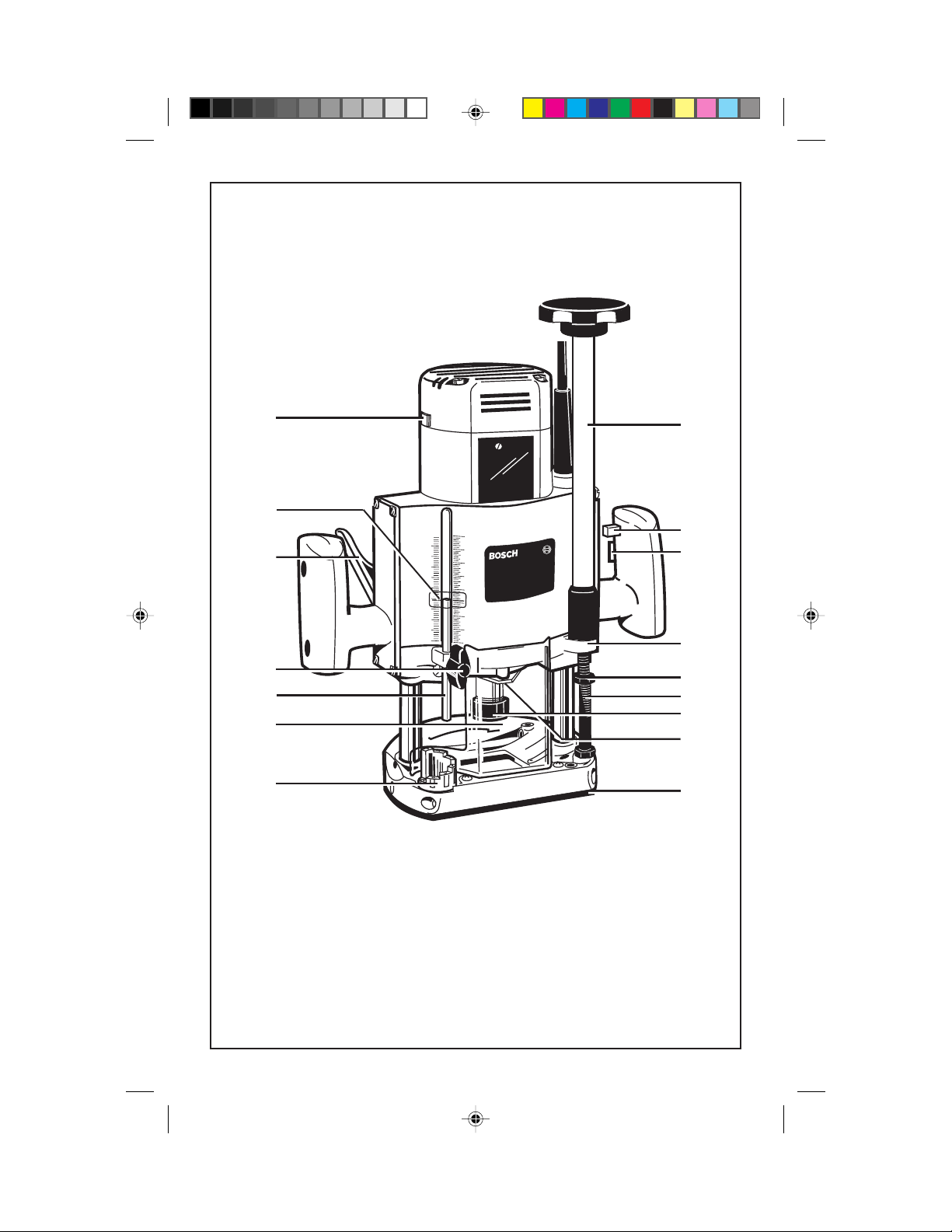
Router Components
1. Depth indicator rod 12. Trigger switch
2. Depth indicator scale 13. Plunge lock/release lever
3. Depth indicator lock/release knob 14. Cast boss
4. Router base 15. Retaining ring
5. Revolving depth turret 16. Collet
6. Stop nut 17. Collet nut
7. Collet chuck assembly 18. Templet guide adaptor
8. Subbase 19. Templet guide
9. Threaded guide rod 20. Bit
10. Spindle lock 21. Variable speed dial (1615EVS)
11. “Lock-ON” button 22. Fine adjustment accessory (1615EVS)
(NOTE: router components not illustrated on page 2 are illustrated elsewhere in this manual)
3
BM 3609929671 1/95 12/7/98, 11:56 AM3

WARNING! “READ ALL INSTRUC-
TIONS”. Failure to follow the SAFETY RULES
identified by the BULLET (•) symbols listed
BELOW and other safety precautions, may
result in serious personal injury. Keep these
operating instructions with this product.
GENERAL SAFETY RULES
for all Power Tools
Work Area
• KEEP WORK AREAS CLEAN. Cluttered
areas and benches invite accidents.
• AVOID DANGEROUS ENVIRONMENT.
Don’t use power tools in damp or wet locations.
Do not expose power tools to rain. Keep work
area well lit.
• AVOID GASEOUS AREAS. Do not operate portable electric tools in explosive atmospheres in presence of flammable liquids or
gases. Motors in these tools normally spark,
and the sparks might ignite fumes.
• KEEP CHILDREN AWAY. Do not let
visitors contact tool or extension cord. All
visitors should be kept away from work areas.
Personal Safety
• GUARD AGAINST ELECTRIC SHOCK.
Prevent body contact with grounded surfaces
such as pipes, radiators, ranges and refrigerator
enclosures. Rubber gloves and non-skid footwear are recommended when working outdoors, where damp or wet ground may be
encountered. A Ground Fault Circuit Interrupter protected power line must be used for
these conditions.
• DRESS PROPERLY. Do not wear loose
clothing or jewelry. They can be caught in
moving parts. Wear protective hair covering to
contain long hair.
• USE SAFETY EQUIPMENT. WEAR
SAFETY GOGGLES or glasses with side
shields. Wear hearing protection during extended use of power tools and dust mask for
dusty operations.
• STAY ALERT. USE COMMON SENSE.
Watch what you are doing. Do not operate tool
when you are tired or under influence of drugs.
•
REMOVE ADJUSTING KEYS AND
WRENCHES.
keys and adjusting wrenches are removed from
Form habit of checking to see that
tool before turning it on.
• AVOID ACCIDENTAL STARTING. Don’t
carry plugged in tool with finger on switch. Be
sure the switch is OFF before being plugged in.
• DON’T OVERREACH. Keep proper footing and balance at all times.
• BEFORE CONNECTING THE TOOL to a
power supply (receptacle, outlet, etc.) be sure
the voltage supplied is the same as that specified on the tool’s nameplate. A power supply
with voltage greater than that specified for the
tool can result in serious injury to the user - as
well as damage to the tool. If in doubt, DO NOT
PLUG IN THE TOOL. Using a power supply
with voltage less than the nameplate rating is
harmful to the motor.
“Volts AC” designated tools are for Alternating
Current 50-60 Hz only. “Volts DC” designated
tools are for Direct Current. Do not use AC
designated tools with DC power supply. Do not
use electronic speed controlled tools with DC
power supply.
Tool Use and Care
• DON’T FORCE TOOL. It will do the job
better and safer at the rate for which it was
designed.
• USE RIGHT TOOL. Don’t force small tool
or attachment to do the job of a heavy-duty tool.
Don’t use tool for purpose not intended - for
example; don’t use a circular saw for cutting
tree limbs or logs.
• SECURE WORK. Use clamps or a vise to
hold work. It’s safer than using your hand and
it frees both hands to operate the tool.
• DON’T ABUSE CORD. Never carry tool by
cord or yank it to disconnect from receptacle.
Keep cord from heat, oil, and sharp edges.
Always keep cord away from the spinning
blade, bits or any other moving part while the
tool is in use.
• OUTDOOR USE EXTENSION CORDS.
When tool is used outdoors, use only extension
cords suitable for use outdoors and marked with
suffix W-A (for UL), or W (for CSA). Refer to
section “Extension Cords”, for proper cord use.
• DISCONNECT TOOLS. When not in use,
before servicing, or when changing blades,
bits, cutters, etc.
• STORE IDLE TOOLS. When not in use,
tools should be stored in dry, high or locked up
place - out of the reach of children.
4
BM 3609929671 1/95 12/7/98, 11:56 AM4
• DO NOT ALTER OR MISUSE TOOL.
These tools are precision built. Any alterations
or modifications not specified is misuse and
may result in a dangerous condition.
• THE USE OF ANY ACCESSORIES not
specified in this manual may create a hazard.
• MAINTAIN TOOLS WITH CARE. Keep
tools sharp and clean for better and safer performance. Follow instructions for lubricating and
changing accessories. Inspect tool cords periodically and if damaged, have repaired by authorized service facility. Inspect extension
cords periodically and replace if damaged. Keep
handles dry, clean and free from oil and grease.
• CHECK DAMAGED PARTS. Before further use of the tool, a guard or other part that is
damaged should be carefully checked to determine that it will operate properly and perform
its intended function. Check for alignment of
moving parts, binding of moving parts, breakage of parts, mounting, and any other conditions that may affect its operation. A guard or
other part that is damaged should be promptly
and properly repaired or replaced. Have defective switches replaced. Do not use tool if switch
does not turn it on or off.
• ALL REPAIRS, ELECTRICAL OR MECHANICAL, should be attempted only by
trained repairmen. Contact the nearest Bosch
Factory Service Center, or Bosch Authorized
Service Center or other competent repair center. Use only Bosch replacement parts, any
other may create a hazard.
Safety Rules for Routers
• If router bit is protruding through the base,
never lay the router down until the motor has
come to a complete standstill.
• Never hold the workpiece in one hand and
the router in other when in use. Always clamp
the material and hold the router securely with
both hands.
• Never use bits that have a cutting diameter
greater than the opening in the base.
• After changing the bits or making any adjustments, make sure the collet nut and any other
adjustment devices are securely tightened before using the router.
• The direction of feeding the router into the
material is very important and it relates to the
direction of bit rotation. When viewing the
router from the top, the bit rotates clockwise.
When the router is located between your body
and the material, the feed direction must be to
the right. If the material is located between your
body and the router, then the feed direction
must be to the left. Feeding the router in the
wrong direction, causes the cutting edge of the
bit to climb out of the work and pull the router
in the direction of this feed.
Double Insulated Tools
• Double Insulation is a design concept
used in electric power tools which eliminates
the need for the three wire grounded power cord
and grounded power supply system. It is a
recognized and approved system by
Underwriter’s Laboratories, CSA and Federal
OSHA authorities.
• Never start the router when the bit is engaged
in the material. The bit’s cutting edge may grab
the material causing the router to get out of
control. Always hold the router with two hands
during start-up. The reaction torque of the
motor can cause the router to twist.
• Always make sure the workpiece is free from
nails and other foreign objects which can cause
the bit and router to jump and damage the bit.
• Always wear safety goggles. If router has a
removable chip deflector, keep it in place when
routing.
• Never touch the router bit or other moving
part during use. After use the router bit is too
hot to be touched by bare hands.
BM 3609929671 1/95 12/7/98, 11:56 AM5
IMPORTANT: Servicing of a tool with
double insulation requires care and knowledge
of the system and should be performed only by
a qualified service technician. WHEN SERVICE IS REQUIRED USE ONLY IDENTICAL REPLACEMENT PARTS.
POLARIZED PLUGS: If your tool is equipped
with a polarized plug (one blade is wider than
the other), this plug will fit in a polarized outlet
only one way. If the plug does not fit fully in the
outlet, reverse the plug. If it still does not fit,
contact a qualified electrician to install the
proper outlet. To reduce the risk of electric
shock do not change the plug in any way.
5
Extension Cords
• Replace damaged cords immediately. Use of
damaged cords can shock, burn or electrocute.
• If an extension cord is necessary, a cord with
adequate size conductors should be used to
prevent excessive voltage drop, loss of power
or overheating. The table below shows the
correct size to use, depending on cord length
and amperage rating on the tool’s nameplate. If
in doubt, use the next heavier gauge. Always
use U.L. and CSA listed extension cords.
Ampere Rating (shown on nameplate)
0- 2.1- 3.5- 5.1- 7.1- 12.1-
2.0 3.4 5.0 7.0 12.0 16.0
25' 18 18 18 18 16 14
50' 18 18 16 16 14 12
75' 18 18 16 14 12 10
100' 18 16 14 12 10
150' 16 14 12 12 Wire Gauge
Cord Length
Note: The smaller the gauge number, the larger
the wire is in the cord.
"SAVE THESE INSTRUCTIONS"
Operating the Tool
Trigger Switch and “Lock-On” Button
Your tool can be turned “ON” or “OFF” by
squeezing or releasing the trigger. Your tool is
also equipped with “Lock-ON” button located
just above the trigger that allows continuous
operation without holding the trigger .
TO LOCK SWITCH ON: Squeeze trigger,
depress button and release trigger.
TO UNLOCK THE SWITCH: Squeeze trigger
and release it without depressing the “LockON” button.
WARNING! if the “Lock-ON” button is con-
tinuously being depressed, the trigger cannot be
released.
WARNING! Hold the tool with both hands
while starting the tool, since torque from the
motor can cause the tool to twist.
Variable Speed with Dial Setting
(1615EVS)
Your router is also equipped with a variable
speed dial 21. The router bit speed can be preset
from 12,000 to maximum nameplate RPM by
rotating the dial to the desired setting. The dial
may be set on or between any of six positions (1
= low through 5 = high). The "Lock-ON"
button may also be used with any setting of the
dial.
The following speeds generally apply, but precise settings are largely determined by
experience with the material being cut. Momentary speed variation is normal when starting
the router until the electronic regulator takes
control.
Dial Setting Material
1-3 Hardwoods, soft plastics,
(12,000 to nonferrous metals,
15,000 RPM) larger diameter router
bits and cutters.
4-5 Softwoods, plastics,
(16,500 to counter tops, smaller
19,000 RPM) diameter router bits and
cutters.
"Soft Start" Feature (1615EVS)
The router is equipped with the "soft start"
feature which gradually increases the starting
speed and torque, reducing the stress that occurs from a high torque start.
Start the tool before applying to work and let
the tool come to full speed before contacting
the workpiece. Lift the tool from the work
before releasing the switch. DO NOT turn the
switch "ON" and "OFF" while the tool is under
load; this will greatly decrease the switch life.
Router Bit Installation and Removal
WARNING! Always disconnect the tool
from the power supply before installing router
bits, accessories or making any adjustments.
Installing a Router Bit
Turn the armature shaft to align the flats with
the spindle lock 10, and push in with thumb to
hold the armature shaft firmly. Next, use the
27mm wrench supplied to loosen the collet
chuck assembly 7 in a counter-clockwise direction (viewed from under the router). Insert the
shank of the router bit into the collet chuck as
6
BM 3609929671 1/95 12/7/98, 11:56 AM6
far as it will go, and then back the shank out until
the cutters are approximately 1/8" to 1/4" away
from the collet nut face. With the bit inserted
and the spindle lock fully engaged, firmly tighten
the collet chuck assembly in a clockwise direction with the 27mm wrench. To avoid damage,
never tighten the collet chuck unless a bit of the
proper shank size is inserted.
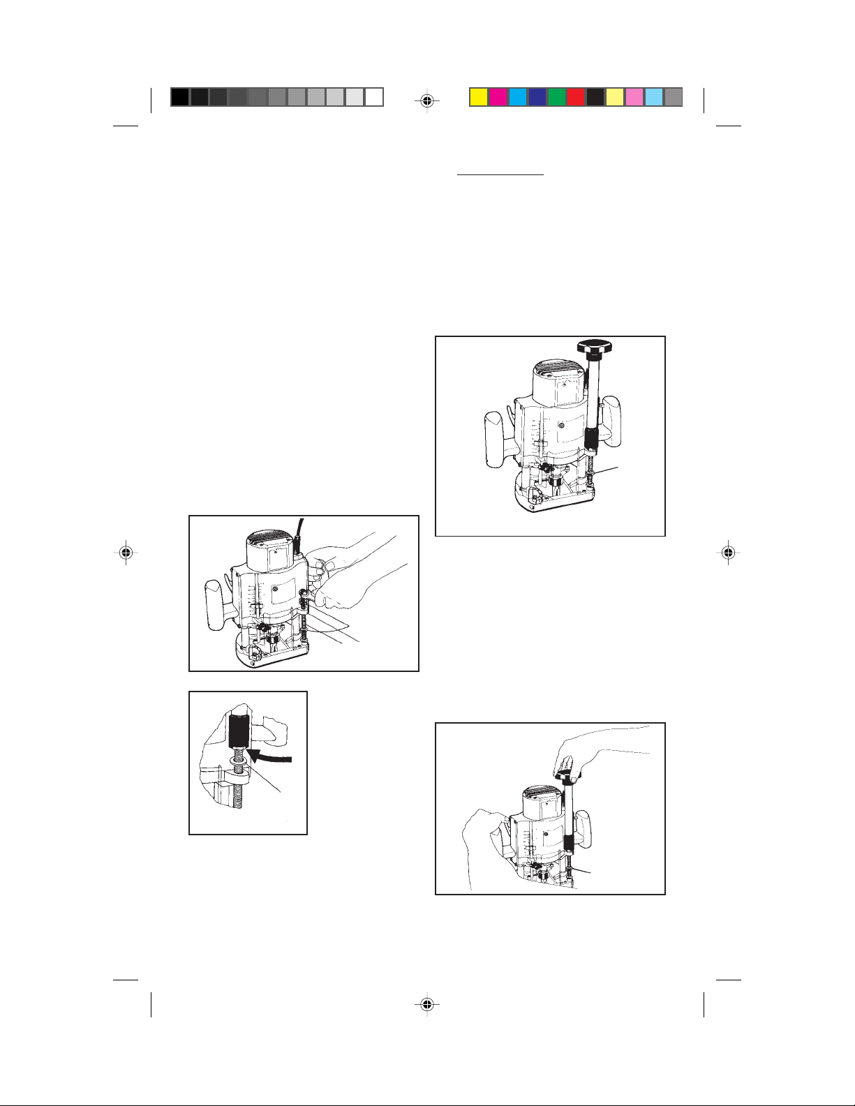
and press the lever with the thumb of the left
hand. The motor may then be raised or lowered
to the desired position. The plunge lock/release
lever is spring-loaded, and will hold the router
motor in position when pressure on the lever is
released. When plunging, always apply uniform firm pressure to both handles to avoid
cocking the motor on the posts.
CAUTION! To minimize run-out and ensure
proper gripping, the bit should be inserted into
the collet as far as possible, and never less than
5/8".
CAUTION! Do not use router bits greater
than 2-5/8" in diameter as they will not fit
through the base casting.
Removing the Router Bit
To remove bit, use the spindle lock and wrench
as described above, and turn the collet chuck
assembly 7 in a counter-clockwise direction.
Once the collet chuck assembly is loosened,
continue to turn the collet chuck until it pulls the
collet free from its taper, and the bit can be
removed.
NOTE: The collet chuck is self-extracting; it is
NOT necessary to strike the collet chuck to free
the router bit.
Collet Chuck Care
With the router bit removed, continue to turn
the collet chuck counter-clockwise until it is
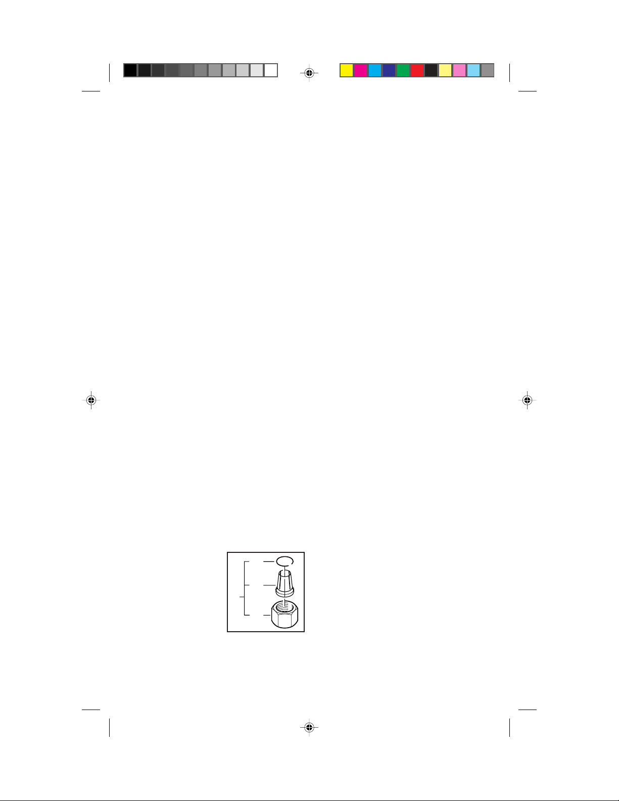
free of the shaft. To assure a firm grip, occasionally blow out the collet chuck with compressed air, and clean the taper in the armature
assembly shaft with a tissue or fine brush. The
collet chuck is made up of three component
parts as illustrated; check to see that the retaining ring 15 is properly located around the collet
16 and seated in the inner groove of the collet
chuck nut 17 and lightly
thread the collet chuck
back onto the armature
shaft. Replace worn or
damaged collet chucks
immediately.
15
16
7
17
Plunge Lock/Release Lever
To release the plunge lock/release lever 13
grasp the router handles firmly with both hands
Indicator Rod and
Revolving Depth Turret
The depth indicator rod 1 and the revolving
depth turret 5 are used to control cutting depth
as follows;
With the bit installed, gently lower the motor
until the tip of the router bit just contacts the
level surface the router is sitting on. This is the
“zero” position, from which further depth adjustments can be accurately made. To set a
desired depth of cut, rotate depth turret until the
lowest step is aligned with the depth indicator
rod. Loosen depth indicator lock/release knob
3 and lower the depth indicator rod until it
contacts the lowest step of the turret. The reading of the red indicator line along the depth
indicator scale 2 now indicates the point at
which the bit just contacts the work, and is used
as a reference point to set the desired depth of
cut.
EXAMPLE: With the bit just contacting the
work surface, depth indicator rod 2 reads 3/4"
with the tip of the rod in contact with the turret.
To achieve a 1/2" depth of cut, loosen knob and
move the rod upward until the red line indicates
1 1/4", and tighten knob. Plunging the router
until the depth rodcontacts the depth turret will
now move the bit into the workpiece 1/2". To be
certain that your settings are accurate, you may
want to make test cuts in scrap material before
beginning work.
It is possible to make progressively deeper cuts
by starting with a higher flat on the depth turret
and rotating the turret to progressively lower
stops until the final cutting depth is reached.
Threaded Guide Rod
The threaded guide rod 9 is fitted with three stop
nuts 6. When not in use, these nuts should be
snugly seated at the top and bottom of the rod so
that they do not interfere with the plunge action.
7
BM 3609929671 1/95 12/7/98, 11:56 AM7
If a shorter stroke is desired, turn the upper stop
7
20
19
8
nut closest to the cast boss 14 on the motor
down to the desired position, and lock in place
by firmly tightening the other upper stop nut
against it. If a fixed depth setting is desired, (no
plunge action) tighten a stop nut on either side
of the boss and the depth of cut will be rigidly
set.
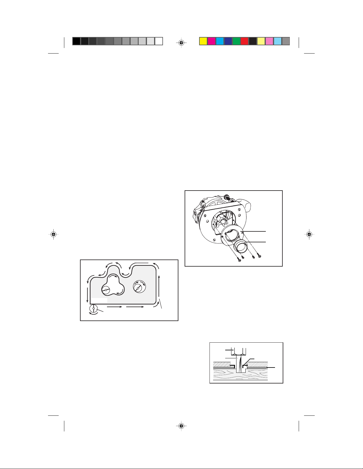
Direction of Feed
The router rotates in a clockwise direction as
viewed from the top. The correct relationship
between direction of bit or cutter rotation and
router feed is shown below. It is very important
to move the router in the proper direction or bit
chatter and rough cutting will be the result.
As an example, to rout a decorative edge on the
front of a table top, you would move the router
from left to right to perform the operation, or
counter-clockwise around the workpiece. If
you were cutting an opening in the center of a
panel, you would feed the router in a clockwise
direction, so that the edge of the opening would
be cut against the rotation of the bit as described, and have a smooth finish. Whenever
you are cutting completely around a workpiece,
it is advisable to cut across the grain first, so any
corner tearout may be smoothed by cutting with
the grain on the second pass.
start the tool when the bit is engaged. Always be
sure the collet nut is tightened securely before
use. Always use bits with the shortest cutting
length necessary to produce the desired cut to
minimize router bit run-out and chatter.
Templet Guides
To use the templet guides 19 that are listed in
the BOSCH catalog, your router is supplied
with a templet guide adaptor 18, which is fastened to the base with the two countersunk
screws provided. Optional templet guides may
be inserted and held in place along their edges
with the two screws provided with the templet
guide. Some templet guides have holes for
mounting, but these holes are not required for
use with the adaptor plate shown, as it grips the
edge of the templet guide.
18
19
Templet guides are used with a number of
accessories which are listed in your BOSCH
catalog. In addition, special templets are easily
prepared for cutting repeated patterns, designs,
WORK
CUTTER
DIRECTION
OF FEED
Rate of Feed
When routing or doing related work in wood
and plastics, the best finishes will result if the
depth of cut and feed rate are regulated to keep
the motor operating at high speed. Feed the
router at a moderate rate. Soft materials generally require a faster feed rate than hard materials.
The router may stall if improperly used or
overloaded. Reduce the feed rate to prevent
possible damage to the tool. Do not attempt to
inlays, and other applications. A templet pattern may be made of plywood, hardboard, metal
or even plastic, and the design can be cut with
a router, jigsaw, or other suitable cutting tool.
Patterns must compensate for the distance between the router bit and the templet guide, as the
final workpiece will differ in size from the
templet
pattern by
that
amount,
due to the
cutter position.
8
BM 3609929671 1/95 12/7/98, 11:56 AM8
(1615EVS) RA1001
Fine Adjustment Accessory
Installation and Operating Instructions
The RA1001 fine-adjustment accessory will
allow precise bit height adjustments on Bosch
routers. It is important to note that this accessory restricts the movement of the router motor
on the plunge base and effectively replaces the
normal plunge action with a threaded feed.
CAUTION; Always disconnect the tool from
the power source before installing bits, accessories, or making any adjustments. Never adjust this accessory when the tool is running or
the bit is in contact with the workpiece.
Installation
1. Plunge router down so that boss O on the
motor is not in contact with nuts J on threaded
guide rod I. Remove the 17mm locknut and two
flat nuts J from rod I with a suitable wrench
(Fig. 1).
Fig. 1
J
O
I
Fig. 2
Place washer K over
threaded rod, and reinstall one of the flat
nuts J about 3/8" from
the top of rod I. A
light film of general
purpose grease may
K
be applied to washer
K to help reduce friction (Fig. 2).
will protrude slightly from the cutaway end of
the RA1001 so that the face of the nut (NOT the
RA1001) will contact washer K. Figure 3
shows the RA1001 properly installed. If desired, 17mm nut J below boss O may be used to
lock the router in a fixed depth setting by
tightening it against the opposite side of boss O.
(Note: Keep the nuts you have removed in a
safe place so that they may be reinstalled on
your router if the RA1001 is removed for any
reason.)
Fig. 3
J
Operation
To use the RA1001, depress the plunge release
lever and turn the RA1001 clockwise to lower,
or counterclockwise to raise the bit. (Note that
one full turn of the knob will raise or lower the
bit approximately .060", or 1.5mm.) It is necessary to exert slight downward pressure on the
router handle opposite the RA1001, to avoid
cocking the motor on the posts (Fig. 4).
Fig. 4
2. Place the threaded end of the RA1001 over
the top of rod I and press it down to compress
the spring until the cutaway portion engages nut
J and thread adjuster onto rod. When the
RA1001 is properly installed, the 17mm nut J
BM 3609929671 1/95 12/7/98, 11:56 AM9
J
9

Deluxe Router Guide
For routing operations such as grooving or
dadoing, it is often necessary to guide the tool
in a line parallel to a straight edge. One method
of obtaining a straight cut is to securely clamp
a board or other straightedge to the work surface, and guide the edge of the router sub-base
along this path. It is best to keep the router in one
position as it is moved along the guide, as this
will produce the straightest cut.
The Bosch deluxe router guide is an accessory
that will guide the router parallel to a straight
edge or around a curved surface. The deluxe
router guide is supplied with two rods and a
series of wing nuts and screws to fasten the
guide and adjust its position relative to the bit.
With the guide installed and adjusted, the router
should be fed normally, keeping the guide in
contact with the edge of the workpiece at all
times. The deluxe router guide may also be
positioned under the router base for operations
where a limited amount of bit exposure is desired.
The Bosch deluxe router guide includes a
fine-adjustment mechanism for extra precision,
and removable face plates for guiding the router
along straight or curved surfaces. For proper
operation, please refer to the instructions which
are included with this accessory.
Chip Extraction
Your BOSCH plunge router may be fitted with
a chip extraction attachment to help keep your
work environment cleaner. This attachment
can be used for general routing, and has an
adjustable brush attachment that is especially
well-suited to grooving applications. Please
see your BOSCH Power Tool distributor for
more details about these and other optional
accessories.
WARNING! Use of any accessory not speci-
fied in this manual or the BOSCH catalog for
use with this tool may create a hazard.
Maintenance and Service
WARNING! Preventive maintenance per-
formed by unauthorized personnel may result
in misplacing of internal wires and components
which could cause serious hazard. We recommend that all tool service be performed at a
Bosch Factory Service Center.
Tool Lubrication
Your Bosch tool has been properly lubricated
and is ready for use. We recommend, that tools
with gears be regreased with a special gear
lubricant every time the brushes are changed.
Carbon Brushes
The brushes and commutator in your Bosch
tool have been engineered for many hours of
dependable service. To maintain peak efficiency of the motor, we recommend that every
two to six months the brushes be examined.
Only genuine Bosch replacement brushes specially designed for your tool should be used.
Bearings
After about 300-400 hours of operation, or at
every second brush change, the bearings should
be replaced at a Bosch Factory Service Center.
Bearings which become noisy (due to heavy
load or very abrasive material cutting) should
be replaced at once to avoid overheating and
motor failure.
Cleaning
WARNING! To avoid accidents, always
disconnect the tool from the power supply
before cleaning or performing any maintenance.
The tool may be cleaned most effectively with
compressed air. Always wear safety goggles
when cleaning tools with compressed air.
Ventilation openings and switch levers must be
kept clean and free of foreign matter. Do not
attempt to clean by inserting pointed objects
through openings.
CAUTION! Certain cleaning agents and
solvents damage plastic parts. Some of these
are: gasoline, carbon tetrachloride, chlorinated
cleaning solvents, ammonia and household
detergents that contain ammonia.
BM 3609929671 1/95 12/7/98, 11:56 AM10
10

WARRANTY
BOSCH
S-B POWER TOOL COMPANY
LIMITED WARRANTY
S-B Power Tool Company (“Seller”) warrants,
to the original purchaser only, that all BOSCH
portable power tools will be free from defects in
material or workmanship for a period of one (l)
year from date of purchase. SELLER’S SOLE
OBLIGATION AND YOUR EXCLUSIVE
REMEDY under this Limited Warranty and, to
the extent permitted by law, any warranty or
condition implied by law, shall be the repair or
replacement of parts, without charge, which are
defective in material or workmanship and which
have not been misused, carelessly handled, or
misrepaired by persons other than Seller or
Authorized Service Stations. To make a claim
under this Limited Warranty, you must return
the complete portable power tool product, transportation prepaid, to any BOSCH Factory Service Center or Authorized Service Station. A
listing of U.S. BOSCH Factory Service Centers
is packed with each BOSCH Power Tool. For
BOSCH Power Tool Authorized Service Stations, please refer to your phone directory.
THIS LIMITED WARRANTY DOES NOT
APPLY TO ACCESSORY ITEMS SUCH AS
CIRCULAR SAW BLADES, DRILL BITS,
ROUTER BITS, JIGSAW BLADES, SANDING BELTS, GRINDING WHEELS AND
OTHER RELATED ITEMS. ANY IMPLIED
WARRANTIES SHALL BE LIMITED IN
DURATION TO ONE (1) YEAR FROM DATE
OF PURCHASE. SOME STATES IN THE
U.S. DO NOT ALLOW LIMITATIONS ON
HOW LONG AN IMPLIED WARRANTY
LASTS, SO THE ABOVE LIMITATION
MAY NOT APPLY TO YOU. IN NO EVENT
SHALL SELLER BE LIABLE FOR ANY INCIDENTAL OR CONSEQUENTIAL DAMAGES (INCLUDING BUT NOT LIMITED
TO LIABILITY FOR LOSS OR PROFITS)
ARISING FROM THE SALE OR USE OF
THIS PRODUCT. SOME STATES IN THE
U.S. DO NOT ALLOW THE EXCLUSION
OR LIMITATION OF INCIDENTAL OR
CONSEQUENTIAL DAMAGES, SO THE
ABOVE LIMITATION OR EXCLUSION
MAY NOT APPLY TO YOU. THIS LIMITED WARRANTY GIVES YOU SPECIFIC
LEGAL RIGHTS, AND YOU MAY ALSO
HAVE OTHER RIGHTS WHICH VARY
FROM STATE TO STATE.
S-B Power Tool Company
4300 W. Peterson Avenue
Chicago, IL 60646-5999
BM 3609929671 1/95 12/7/98, 11:56 AM11
11

Fiche technique - Toupie de coupe en plongée
Numéro de modèle 1615 1615EVS
Numéro d’identification 0 601 615 0.. 0 601 615 7..
Capacité de la douille 1/4", 3/8", 1/2" de diamètre 1/4", 3/8", 1/2" de diamètre
Taille maximale du fer 2-5/8" de diamètre 2-5/8" de diamètre
(REMARQUE: Cet outil ne fonctionne qu’au courant alternatif (c.a.).
Accessoires
Ensemble mandrin-douille 1/2"*
Ensemble mandrin-douille 3/8"
Ensemble mandrin-douille 1/4"*
Clé pour écrou de douille 27 mm*
Adaptateur pour guide de gabarit et 2 vis*
Guide de luxe
Coffret en acier
Accessoire de réglage précis* *
Raccord d’aspirateur
Boyau d’aspirateur
Adaptateur boyau/aspirateur
( * = Équipement standard )
( * * = Équipement standard 1615EVS Seulement )
Composants de la toupie
1. Guide de profondeur
2. Règle de profondeur
3. Bouton de serrage du guide
4. Base
5. Tourelle de profondeur tournante
6. Écrou d’arrêt
7. Ensemble mandrin/douille
8. Embase
9. Tige de guidage filetée
10. Dispositif de verrouillage de l’arbre
11. Bouton de blocage en marche
(REMARQUE: les composants de la toupie qui ne sont pas illustrés à la page 2 le sont ailleurs
dans le présent manuel).
BM 3609929671 1/95 12/7/98, 11:56 AM12
12. Gâchette de commande
13. Levier de réglage en plongée
14. Bossage coulé
15. Anneau de retenue
16. Douille
17. Écrou de douille
18. Adaptateur pour guide de gabarit
19. Guide de gabarit
20. Fer
21. Cadran de vitesse (1615EVS)
22. Accessoire de réglage précis (1615EVS)
12

AVERTISSEMENT ! «LISEZ
ATTENTIVEMENT TOUTES LES INSTRUCTIONS». Faute d’observer les
RÈGLES DE SÉCURITÉ précédées d’un point
noir (°) et les autres consignes du présent manuel
risque de vous exposer à de graves blessures.
Conservez ces instructions à portée de la main.
RÈGLES GÉNÉRALES DE
SÉCURITÉ
pour tous les outils motorisés
Lieu de travail
• TRAVAILLEZ DANS LA PROPRETÉ. Les
endroits et les établis encombrés invitent les
accidents.
• ÉVITEZ LES ENVIRONNEMENTS
DANGEREUX. N’utilisez pas les outils
électriques en lieux humides ou mouillés.
N’exposez pas les outils motorisés à la pluie.
Assurez-vous que l’endroit est adéquatement
éclairé.
• ÉVITEZ LES ENVIRONNEMENTS
GAZEUX. N’utilisez pas les outils électriques
portatifs en atmosphères explosives en présence
de liquides ou de gaz inflammables. Les moteurs
de ces outils émettent normalement des
étincelles qui risquent d’enflammer les vapeurs.
• GARE AUX ENFANTS. Ne permettez pas
aux visiteurs de toucher l’outil ou la rallonge.
Tenez-les à distance raisonnable du lieu de
travail.
Sécurité personnelle
• GARE AUX DÉCHARGES
ÉLECTRIQUES. Évitez tout contact avec les
surfaces mises à la terre telles que tuyaux,
radiateurs, cuisinières et enceintes de
réfrigérateurs. Pour le travail à l’extérieur, par
temps humide ou sur sol mouillé, il est
recommandé de porter des gants en caoutchouc
et des chaussures à semelle antidérapante. Dans
ce cas, vous devez utiliser une prise de courant
protégée par disjoncteur de fuite à la terre.
• PORTEZ DES VÊTEMENTS
CONVENABLES. Ne portez pas de vêtements
amples ni de bijoux car ils risquent de
s’accrocher dans les pièces mobiles. De même,
pour les cheveux longs, nous conseillons le port
d’un serre-tête.
• UTILISEZ L’ÉQUIPEMENT DE
SÉCURITÉ. Portez des lunettes de sécurité ou
lunettes à coques latérales. Portez des protègeoreilles lors des travaux de longue durée et un
masque protecteur si la situation l’exige.
• SOYEZ VIGILANT, FAITES PREUVE DE
DISCERNEMENT. Agissez prudemment.
N’utilisez pas l’outil quand vous êtes fatigué ou
sous l’influence de stupéfiant.
• ENLEVEZ LES CLÉS DE RÉGLAGE ET
AUTRES. Prenez l’habitude de voir à ce qu’elles
soient mises de côté avant de mettre l’outil en
marche.
• ÉVITEZ LA MISE EN MARCHE
ACCIDENTELLE. Ne transportez pas un outil
en marche. Assurez-vous que l’interrupteur est
en position d’arrêt avant de le brancher.
• TRAVAILLEZ AVEC APLOMB. Tenezvous bien d’aplomb et en équilibre en tout
temps.
• AVANT DE BRANCHER L’OUTIL à une
prise de courant, rassurez-vous que la tension
correspond à celle spécifiée sur la plaquette
emblématique de l’outil. Une tension supérieure
à celle recommandée pour l’outil risque de
blesser sérieusement l’utilisateur sans
mentionner l’endommagement de l’outil. NE
BRANCHEZ PAS L’OUTIL à moins que vous
soyez absolument satisfait. Le raccordement à
une source de courant dont la tension est
inférieure à celle indiquée sur la plaquette
endommagera le moteur.
Les outils portant la désignation «AC» ne
s’alimentent que de courant alternatif de 50-60
Hz. Les outils portant la désignation «DC»
s’alimentent de courant continu. N’enfichez
pas d’outils CA à une source d’alimentation c.c.
Ne branchez pas les outils àrégulateur
électronique de vitesse à une source
d’alimentation c.c.
Utilisation et entretien
• N’ABUSEZ PAS DE L’OUTIL. Il est plus
efficace et sûr au régime pour lequel il a été
destiné.
• UTILISEZ L’OUTIL APPROPRIÉ. Ne
forcez pas un petit outil ou un accessoire
àeffectuer le travail d’un de plus grosse taille.
N’utilisez pas l’outil à tort et à travers - par
exemple - n’utilisez pas une scie circulaire pour
tailler les branches d’arbres ou les bûches.
• FIXEZ LE MATÉRIAU EN PLACE.
13
BM 3609929671 1/95 12/7/98, 11:56 AM13

Utilisez des serre-joints ou un étau. C’est
beaucoup plus sûr et vous pouvez manier l’outil
des deux mains.
• N’ABUSEZ PAS DU CORDON. Ne
transportez jamais l’outil par le cordon et ne
tirez jamais sur ce dernier pour le débrancher.
Protégez le cordon de la chaleur, de l’huile et
des bords tranchants. Gardez toujours le cordon à bonne distance de la lame, des accessoires
ou autres pièces mobiles de l’outil en marche.
• CORDONS DE RALLONGE POUR
EXTÉRIEUR. Quand vous utilisez l’outil à
l’extérieur, n’employez que des rallonges
destinées à tel usage et portant les suffixes
d’homologation, soit W-A (pour les UL) soit W
(pour l’ACNOR). Voir le tableau «Dimensions
des rallonges recommandées».
• DÉBRANCHEZ LES OUTILS. Quand ils
ne servent pas; avant l’entretien; avant de
changer les lames, les mèches, les couteaux,
etc.
• RANGEZ LES OUTILS NE SERVANT
PAS. Suivant leur usage, les outils devraient
être rangés dans un endroit sec, élevé ou sous
clé - hors de la portée des enfants.
• NE MODIFIEZ NI ABUSEZ DE L’OUTIL.
Ces outils sont extrêmement précis. Tout
changement ou modification non recommandé
constitue un mésusage risquant d’avoir de graves
répercussions.
• L’USAGE D’ACCESSOIRES AUTRES que
ceux recommandés dans le présent manuel peut
être dangereux.
• TRAITEZ LES OUTILS AVEC SOIN.
Maintenez-les bien propres et bien à point pour
qu’ils fonctionnent en douceur. Observez les
directives concernant le graissage et le
changement des accessoires. Examinez
périodiquement l’état des cordons de l’outil et,
au besoin, confiez-en la réparation à un poste
d’entretien agréé. Examinez périodiquement
l’état des cordons de rallonge et remplacez-les
au besoin. Maintenez les poignées sèches,
propres, sans souillure d’huile et de graisse.
• RECHERCHEZ LES PIÈCES
ENDOMMAGÉES. Avant d’utiliser l’outil,
examinez soigneusement l’état des pièces telles
que le protecteur pour vous assurer qu’elles
fonctionnent correctement. Vérifiez
l’alignement et la liberté de fonctionnement des
pièces mobiles, l’état et le montage des pièces
et toutes autres conditions susceptibles d’affecter
défavorablement le fonctionnement. Il faut
réparer ou remplacer toute pièce ou tout
protecteur dont l’état laisse à désirer. Faites
remplacer tout interrupteur défectueux.
N’utilisez pas un outil dont l’interrupteur ne
fonctionne pas correctement.
• TOUTES LES RÉPARATIONS,
ÉLECTRIQUES OU MÉCANIQUES,
devraient être exécutées par des techniciens
compétents. Confiez-les au centre de serviceusine le plus proche, à un autre centre de service
après-vente Bosch agréé ou, encore, à un poste
d’entretien renommé. Pour vous éviter des
ennuis, exigez toujours les pièces de rechange
Bosch.
Règles de sécurité concernant
les toupies
• Ne mettez jamais la toupie en marche alors
que le fer est enfoui dans le matériau. Le
tranchant du fer peut gripper dans le matériau
rendant la toupie incontrôlable. Tenez toujours
la toupie à deux mains au moment de la mettre
en marche. Le couple du moteur de la toupie
peut donner un contrecoup.
• Assurez-vous toujours qu’aucun clou et autres
obstacles semblables ne soient enfouis dans la
pièce, car ils peuvent faire sauter la toupie et le
fer et abîmer ce dernier.
• Portez toujours des lunettes de sécurité. Si la
toupie est équipée d’un sac à copeaux amovible,
assurez-vous qu’il est en place.
• Évitez de toucher au fer ou autre pièce mobile de la toupie pendant l’usage. Même après
l’usage, le fer prend assez de temps à se refroidir.
• Ne posez jamais la toupie de côté tant que le
moteur ne soit totalement au repos, si le fer fait
saillie par rapport à la base.
• Ne tenez jamais le matériau d’une main et la
toupie en marche de l’autre. Il importe de bien
assujettir le matériau et de tenir fermement la
toupie à deux mains.
• N’utilisez jamais des fers dont le diamètre de
coupe est supérieur à celui de l’ouverture
pratiquée dans la base.
• Après le remplacement des fers ou un réglage
quelconque, assurez-vous que l’écrou de la
douille et les autres dispositifs d’assemblage
soient fermement serrés avant de mettre la
toupie en marche.
• Le sens de déplacement de la toupie dans le
14
BM 3609929671 1/95 12/7/98, 11:56 AM14

matériau est très important et il se rapporte au
sens de rotation du fer. En regardant du dessus
de la toupie, le fer tourne dans le sens des
aiguilles d’une montre. Lorsque la toupie se
trouve entre l’utilisateur et le matériau, le sens
de déplacement doit être vers la droite. Par
contre, si le matériau se trouve entre l’utilisateur
et la toupie, le sens de déplacement doit être
vers la gauche. Le déplacement dans le mauvais
sens forcera le tranchant du fer à grimper hors
du matériau entraînant la toupie dans le même
sens.
Outils à double isolation
• La double isolation est utilisée dans les
outils électriques pour éliminer le besoin de
cordon d’alimentation trois fils, dont la prise de
terre, et de dispositif d’alimentation à prise de
terre. Elle est homologuée par l’Underwriter’s
Laboratories, l’ACNOR et l’OSHA.
rallonges recommandées en fonction de leur
longueur et de l’intensité indiquée sur la
plaquette emblématique de l’outil. En cas de
doute, optez pour le prochain calibre inférieur.
Utilisez toujours des rallonges homologuées
par l’U.L. et l’ACNOR.
Intensité nominale(figurant sur la plaquette emblématique)
0- 2.1- 3.5- 5.1- 7.1- 12.1-
2.0 3.4 5.0 7.0 12.0 16.0
25' 18 18 18 18 16 14
50' 18 18 16 16 14 12
75' 18 18 16 14 12 10
100' 18 16 14 12 10
150' 16 14 12 12 calibre du fil
Longueur de rallonge
REMARQUE : Plus le calibre est petit, plus le
fil est gros.
‹‹CONSERVEZ CES INSTRUCTIONS››
IMPORTANT : L’entretien d’un outil à
double isolation exige la connaissance du
système et la compétence d’un technicien
qualifié. EN CAS D’ENTRETIEN,
N’UTILISEZ QUE DES PIÈCES DE
RECHANGE IDENTIQUES.
FICHES POLARISÉES. Si votre outil est
équipé d’une fiche polarisée (une lame plus
large que l’autre) elle ne s’enfiche que d’une
manière dans une prise polarisée. Si la fiche
n’entre pas à fond dans la prise, tournez-la d’un
demi-tour. Si elle refuse encore d’entrer,
demandez à un électricien qualifié d’installer
une prise appropriée. Afin de réduire le risque
de choc électrique, ne modifiez la fiche d’aucune
façon.
Rallonges
• Remplacez immédiatement toute rallonge
endommagée. L’utilisation de rallonges
endommagées risque de provoquer un choc
électrique, des brûlures ou l’électrocution.
• En cas de besoin d’une rallonge, utilisez un
cordon de calibre satisfaisant pour éviter toute
chute de tension, perte de courant ou surchauffe.
Le tableau ci-dessous indique le calibre des
Mode d’emploi
Gâchette de commande et bouton de
blocage en marche
Votre outil peut être mis en marche ou au repos
à l’enfoncement ou au relâchement de la
gâchette. Il est aussi équipé, juste au-dessus de
la gâchette, d’un bouton de blocage en marche
qui maintient l’interrupteur sous tension sans
avoir à appuyer sur la gâchette de commande.
BLOCAGE DE L’INTERRUPTEUR EN
MARCHE: appuyez sur la gâchette, enfoncez
le bouton et relâchez la gâchette.
DÉBLOCAGE DE L’INTERRUPTEUR:
appuyez sur la gâchette et relâchez-la sans
toucher au bouton de blocage en marche.
AVERTISSEMENT ! Le relâchement de
la gâchette est impossible si le bouton de blocage
en marche est maintenu enfoncé.
AVERTISSEMENT ! Tenez l’outil à deux
mains au départ car le couple du moteur peut le
faire tourner sur lui-même.
Variateur de vitesse à cadran
Votre toupie est aussi dotée d’un variateur de
15
BM 3609929671 1/95 12/7/98, 11:56 AM15

vitesse à cadran 21. Au moyen du cadran, vous
pouvez prérégler la vitesse du fer depuis 12
000 tr/mn jusqu’au régime maximal spécifié
sur la plaquette de l’outil. Le cadran peut être
réglé sur ou entre n’importe lequel des six
régimes (depuis 1 = le plus bas jusqu’à 5 = le
plus élevé). Le bouton de blocage en marche
peut être utilisé sur tous les réglages du cadran.
En général, les régimes suivants sont
recommandés, mais l’expérience avec le
matériau utilisé peut dicter des réglages
différents. La variation momentanée du régime
est normale à la mise en marche de la toupie
jusqu’à ce que le régulateur électronique prenne
charge.
le pouce pour immobiliser l’arbre en place.
Ensuite, au moyen de la clé 27 mm fournie,
desserrez l’ensemble mandrin-douille 7 dans le
sens contraire de celui des aiguilles d’une montre
(vu du dessous de la toupie). Introduisez la tige
du fer à fond dans la douille du mandrin, puis
retirez la tige jusqu’à ce que les couteaux soient
environ entre 1/8" et 1/4" de la face de l’écrou
de la douille. Une fois le fer en place et le
dispositif de verrouillage de l’arbre solidement
engagé, serrez fermement l’ensemble mandrindouille dans le sens des aiguilles d’une montre
avec la clé de 27 mm. Pour éviter le risque
d’endommagement, ne serrez jamais le mandrin
sans qu’un fer à tige de taille convenable y soit
inséré.
Réglage du cadran Matériau
1-3 Bois durs, plastiques
(12 000 - mous, métaux non-ferreux,
15 000 tr/mn) fers et couteaux de toupie
de plus grand diamètre
4-5 Bois mous, plastiques,
(16 500 - comptoirs, fers et
19 000 tr/mn) couteaux de toupie
de plus petit diamètre
Démarrage en douceur
La toupie est dotée d’un dispositif de démarrage
en douceur qui assure l’augmentation graduelle
de la vitesse et du couple, réduisant ainsi la
tension qui accompagne le lancement à couple
élevé.
Mettez l’outil en marche et attendez qu’il
atteigne la vitesse maximale avant de le poser
sur la pièce. De même, soulevez-le avant d’en
relâcher l’interrupteur. Pour prolonger la durée
de l’interrupteur, évitez de le mettre sous tension et hors tension pendant que l’outil est à
l’oeuvre.
Pose et dépose des fers
AVERTISSEMENT ! Débranchez toujours
l’outil de la source d’alimentation avant de
changer les fers, les accessoires ou d’effectuer
des réglages.
Pose d’un fer
Tournez l’arbre pour aligner les plats avec le
dispositif de verrouillage 10, puis poussez avec
MISE EN GARDE ! Pour minimiser le
risque d’excentricité et assurer le serrage
approprié, le fer devrait être enfoncé aussi loin
que possible dans la douille, jamais moins que
5/8".
MISE EN GARDE ! N’utilisez pas des fers
de diamètre supérieur à 2-5/8" car ils ne
passeraient pas dans l’ouverture de la base.
Dépose du fer
Pour déposer le fer, servez-vous du dispositif de
verrouillage de l’arbre et de la clé, comme il est
décrit précédemment et tourner l’ensemble
mandrin-douille 7 dans le sens contraire de
celui des aiguilles d’une montre. Quand
l’ensemble mandrin-douille est desserré,
continuez de tourner jusqu’à ce que la douille se
déloge du cône et que vous puissiez retirer le
fer.
REMARQUE : L’extraction de l’ensemble
mandrin-douille s’accomplit sans effort; il n’est
PAS nécessaire de frapper le mandrin pour
déloger le fer.
Soin de l’ensemble mandrin-douille
Quand le fer est enlevé, continuez de tourner
l’ensemble mandrin-douille dans le sens
contraire de celui des aiguilles d’une montre
jusqu’à ce qu’il se détache de l’arbre. Pour
assurer un serrage adéquat, nettoyez
occasionnellement l’ensemble à l’air comprimé
et nettoyez le cône de l’arbre avec un chiffon ou
une brosse douce. Comme le montre
16
BM 3609929671 1/95 12/7/98, 11:56 AM16

l’illustration,
l’ensemble mandrindouille est constitué de
trois éléments.
Assurez-vous que
l’anneau de retenue 15
est bien en place autour
de la douille 16, à fond
dans la rainure intérieure de l’écrou 17 de la
douille, puis vissez légèrement l’ensemble
mandrin-douille sur l’arbre. Remplacez les
ensembles mandrin-douille usés ou
endommagés immédiatement.
15
16
7
17
Levier de réglage de la plongée
Pour desserrer le levier de réglage en plongée
13, saisissez fermement les poignées de la toupie
des deux mains et, avec le pouce de la main
gauche, appuyez sur le levier. Le moteur peut
être alors réglé à la hauteur désirée. Étant donné
qu’il est à ressort, le levier maintiendra le moteur
en place au relâchement. Lors de la coupe en
plongée, appuyez toujours fermement à force
égale sur les deux poignées pour éviter d’incliner
le moteur sur les poteaux.
Guide de profondeur et tourelle
tournante
Le guide de profondeur 1 et la tourelle tournante
5 servent à régler la profondeur de coupe comme
suit:
Le fer en place, abaissez délicatement le moteur
jusqu’à ce que la pointe du fer affleure à peine
la surface sur laquelle la toupie repose. C’est en
effet le «point mort» à partir duquel il est
possible d’effectuer d’autres réglages avec
précision. Pour obtenir la profondeur de coupe
désirée, tournez la tourelle de profondeur jusqu’à
ce que le plus bas gradin soit vis-à-vis le guide
de profondeur. Desserrez le bouton de serrage
du guide 3 et baissez le guide jusqu’à ce qu’il
touche au plus bas gradin de la tourelle. La
valeur à la ligne rouge, le long de la règle de
profondeur 2, représente effectivement le point
auquel le fer effleure à peine la surface du
matériau et cette valeur est utilisée à titre de
référence pour réaliser la profondeur de coupe
désirée.
EXEMPLE : Le fer touchant à peine la surface
du matériau, le guide de profondeur 2 enregistre
3/4" alors que la pointe du guide appuie sur la
tourelle. Pour réaliser une coupe de 1/2" de
profondeur, desserrez le bouton et remontez le
guide jusqu’à ce que la ligne rouge indique 1-1/
4", puis resserrez le bouton. Le fait de plonger
la toupie jusqu’à ce que le guide de profondeur
appuie sur la tourelle permettra d’enfouir le fer
1/2" dans la pièce. Pour vous rassurer que vos
réglages sont exacts, vous auriez intérêt à faire
l’essai dans des retailles au préalable.
Il est possible d’exécuter des coupes
progressivement plus profondes en commençant
par un gradin plus élevé et en tournant
graduellement la tourelle vers des gradins
inférieurs jusqu’à ce vous atteigniez la
profondeur de coupe désirée.
Tige de guidage filetée
La tige de guidage filetée 9 est dotée de trois
écrous d’arrêt 6. Quand ils ne servent pas, ces
écrous devraient être serrés au haut et au bas de
la tige, de sorte qu’ils ne nuisent d’aucune
façon. Si vous désirez raccourcir la course,
tournez l’écrou d’arrêt supérieur le plus proche
du bossage coulé 14 vers le bas à la position
voulue et immobilisez-le fermement en place
en serrant l’autre écrou d’arrêt supérieur sur lui.
Si vous désirez un réglage fixe (sans plongée),
serrez un écrou d’arrêt de chaque côté du
bossage.
Déplacement de la toupie
Vue du dessus, la toupie tourne dans le sens des
aiguilles d’une montre. La correcte relation
entre le sens de rotation du fer ou du couteau et
celui du déplacement de la toupie est la suivante.
Il importe de diriger la toupie dans le sens
approprié, car autrement le fer broute et produit
une coupe plutôt grossière.
Par exemple, pour exécuter une coupe décorative
dans le bord avant d’un dessus de table, vous
déplaceriez la toupie de gauche à droite ou dans
le sens contraire de celui des aiguilles d’une
montre autour de la pièce. Pour tailler une
ouverture dans le centre d’un panneau, vous
déplaceriez la toupie dans le sens des aiguilles
d’une montre, de sorte que le bord de l’ouverture
soit taillé contre la rotation du fer, tel qu’il est
décrit, et présente un fini doux. Dans le cas de
17
BM 3609929671 1/95 12/7/98, 11:56 AM17

coupe tout le tour d’une pièce, il est préférable
7
20
19
8
de couper contre les fibres d’abord, de sorte que
le déchirement des coins puisse être adouci en
repassant dans le sens des fibres ensuite.
WORK
DIRECTION
CUTTER
COUTEAU
SENS DE
OF FEED
DÉPLACEMENT
Vitesse de déplacement
Vous obtiendrez de meilleurs résultats dans le
bois ou les plastiques, si la profondeur de coupe
et la vitesse de déplacement que vous choisissez
favorisent le fonctionnement à régime élevé du
moteur. Travaillez à vitesse modérée.
Normalement, les matériaux mous exigent une
vitesse plus rapide que les matériaux durs.
Le mésusage ou la surcharge peut caler le
moteur. Ralentissez pour éviter tout
endommagement de l’outil. Ne tentez pas de
mettre l’outil en marche alors que le fer est
enfoui. Assurez-vous toujours que l’écrou de la
douille est fermement serré avant l’usage. Pour
minimiser l’excentricité ou le broutage du fer,
utilisez toujours des fers dont la longueur exigée
pour effectuer la coupe désirée est la plus courte.
Guides de gabarit
Pour utiliser les guides de gabarit figurant dans
le catalogue BOSCH, votre toupie est
accompagnée d’un adaptateur 18 pour guides
de gabarit qui s’attache à la base au moyen des
deux vis à tête conique fournies. Les guides de
gabarit facultatifs peuvent être introduits et
maintenus en place le long de leurs rebords par
les deux vis qui les accompagnent. Certains
guides de gabarit sont pourvus de trous
d’assemblage, mais ceux-ci ne sont pas
nécessaires lors de l’usage avec l’adaptateur
montré, puisqu’il capte le bord du guide.
Les guides de gabarit sont utilisés de concert
avec une foule d’accessoires figurant dans votre
catalogue BOSCH. De plus, il est facile de
fabriquer des gabarits spéciaux pour la coupe
répétitive de patrons, dessins, modèles et autres.
On peut fabriquer un patron à partir d’une pièce
de contreplaqué, d’agglomérés, de métal ou
même de plastique; le dessin peut être découpé
à l’aide d’une toupie, scie sauteuse ou autre
outil convenable. Les patrons doivent prendre
en considération la distance entre le fer et le
guide de gabarit, étant donné que la dimension
finale
différera
d’autant,
en raison
de la position du
fer.
Instructions de pose et D’utilisation
De L’accessoire de Réglage de
Précision RA1001 (1615EVS)
L’accessoire de réglage de précision RA1001
permet des réglages précis de la hauteur des
mèches sur les toupies Bosch. Il convient de
noter que cet accessoire restreint le mouvement
du moteur de la toupie sur la base de plongée et
remplace efficacement l’action normale de
plongée par une alimentation filetée.
AVERTISSEMENT : Débranchez toujours
l’outil de la prise de courant avant de poser des
mèches ou des accessoires, ou d’effectuer quel-
18
19
que réglage que ce soit. Ne réglez jamais cet
accessoire pendant que l’outil est en marche ou
que la mèche est en contact avec le matériau.
Pose
1. Plongez la toupie vers le bas de manière à ce
18
BM 3609929671 1/95 12/7/98, 11:56 AM18

que l’ergot O sur le moteur ne soit pas en
contact avec les écrous J sur la tige de guidage
filetée I. Retirez le contre-écrou de 17 mm et
deux écrous plats J de la tige I à l’aide d’une clé
adéquate (fig. 1).
Fig. 1
J
O
I
Fig. 2
Placez la rondelle K
par-dessus la tige
filetée et reposez l’un
des écrous plats J à
environ 3/8" depuis
le dessus de la tige I.
Une mince pellicule
K
de graisse d’usage
général peut être
appliquée sur la
rondelle K pour aider à réduire la friction (fig.
2).
Fig. 3
J
Fonctionnement
Pour utiliser le RA1001, appuyez sur le levier
de dégagement de plongée et tournez le RA1001
en sens horaire pour baisser, ou en sens antihoraire pour lever la mèche. (Il convient de
remarquer qu’un tour complet du bouton lèvera
ou baissera la mèche d’environ 0,060" ou
1,5 mm.) Il faut exercer une légère pression
vers le bas sur la poignée de la toupie en sens
opposé au RA1001 de manière à éviter de
basculer le moteur de côté sur les montants
(fig. 4).
Fig. 4
2. Placez l’extrémité filetée du RA1001 pardessus la partie supérieure de la tige I et pressezla vers le bas de manière à comprimer le ressort
jusqu’à ce que la partie découpée engage l’écrou
J et filetez le régleur sur la tige. Lorsque le
RA1001 est posé adéquatement, l’écrou J de 17
mm fait légèrement saillie depuis l’extrémité
découpée du RA1001 de manière à ce que la
face de l’écrou (NON le RA1001) vienne en
contact avec la rondelle K. La figure 3 montre
le RA1001 posé adéquatement. Si désiré, l’écrou
J de 17 mm sous l’ergot O peut être employé
pour verrouiller la toupie à un réglage fixe de
profondeur en le serrant contre le côté opposé
de l’ergot O.
(Remarque : Conservez les écrous déposés en
lieu sûr de manière à pouvoir les réinstaller sur
la toupie si le RA1001 est déposé pour quelque
motif que ce soit.)
BM 3609929671 1/95 12/7/98, 11:56 AM19
J
Guide de luxe
Pour les travaux à la toupie tels que le rainurage,
on doit souvent guider l’outil dans un plan
parallèle à une règle. Une façon d’exécuter une
coupe droite est d’assujettir à la surface du
matériau, au moyen de serres, une planche ou
autre règle et de diriger le bord de l’embase de
la toupie le long de ce guide de coupe. Pour de
meilleurs résultats, il est recommandé de
maintenir la toupie dans la même position alors
que vous la déplacez le long du guide.
19

Le guide de luxe Bosch est un accessoire qui
permet de maintenir la toupie parallèle à une
surface rectiligne ou curviligne. Le guide de
luxe est accompagné de deux tiges et d’un
nombre d’écrous à ailettes et de vis de fixation
et de réglage. Le guide en place et bien réglé,
déplacez la toupie normalement en le maintenant
en contact avec le bord de la pièce en tout temps.
De même, le guide de luxe peut être fixé audessous de la base de la toupie lorsque vous ne
désirez exposer le fer que partiellement. Le
guide de luxe Bosch comprend un mécanisme
de réglage précis et des plateaux amovibles
pour guider la toupie le long des surfaces
rectilignes et curvilignes. Le mode d’emploi
est inclus avec l’accessoire.
Extraction des copeaux
Vous pouvez équiper votre toupie BOSCH d’un
extracteur de copeaux qui permet de travailler
dans la propreté. Cet accessoire, qui sert au
toupillage général, comporte une brosse réglable
qui convient surtout aux travaux de rainurage.
Pour tous les détails sur les accessoires
facultatifs, consultez votre distributeur d’outils
motorisés BOSCH.
AVERTISSEMENT ! L’emploi
d’accessoires autres que ceux recommandés
dans le présent manuel ou dans le catalogue
BOSCH peut être dangereux.
Maintenance et entretien
AVERTISSEMENT ! L’entretien préventif
prodigué par des personnes non autorisées peut
être dangereux. Il est recommandé de confier
l’entretien et la réparation de l’outil à un centre
de service-usine Bosch.
Balais de charbon
Les balais et le collecteur de votre outil Bosch
ont été conçus pour donner plusieurs heures de
fonctionnement sans aléas. Pour maintenir le
moteur en pleine forme, nous recommandons
d’examiner les balais tous les deux à six mois.
Vous ne devriez exiger que les balais de rechange
d’origine Bosch qui conviennent spécialement
à votre outil.
Roulements
Après environ 300 à 400 heures d’utilisation,
ou à tous les deux remplacements des balais, il
faudrait confier le remplacement des roulements
à un centre de service-usine Bosch. Les
roulements qui sont devenus bruyants (à la suite
d’usage dans des matériaux très abrasifs ou de
durs efforts) devraient être remplacés à l’instant
pour éviter la surchauffe et la défaillance du
moteur.
Nettoyage
AVERTISSEMENT ! Pour éviter le risque
d’accidents, débranchez toujours l’outil de la
prise de courant avant de procéder au nettoyage
ou à l’entretien. Vous pouvez très bien le
nettoyer à l’air comprimé. Dans ce cas, portez
toujours des lunettes de sécurité.
Gardez les prises d’air et les interrupteurs propres
et libres de saletés. N’essayez pas de les nettoyer
en introduisant des objets pointus dans leurs
ouvertures.
MISE EN GARDE ! Certains produits de
nettoyage et dissolvants dont la gazoline, le
tétrachlorure de carbone, les nettoyeurs chlorés,
l’ammoniaque et les détergents ménagers
contenant de l’ammoniaque peuvent abîmer les
pièces en plastique.
Graissage de l’outil
Votre outil Bosch a été convenablement graissé
et est prêt à utiliser. Il est recommandé que les
outils à engrenages soient regraissés avec une
graisse spéciale à l’occasion de tout
remplacement de balais.
BM 3609929671 1/95 12/7/98, 11:56 AM20
20

GARANTIE
GARANTIE LIMITÉE
BOSCH
S-B POWER TOOL COMPANY
TELS QUE LAMES DE SCIES
CIRCULAIRES, MÈCHES DE PERCEUSES,
FERS DE TOUPIES, LAMES DE SCIES
SAUTEUSES, COURROIES DE PONÇAGE,
MEULES ET AUTRES ARTICLES DU
GENRE.
S-B Power Tool Company («Vendeur») garantit
à l’acheteur originel d’outils électriques portatifs
Bosch (et uniquement à celui-ci) que lesdits
outils sont et resteront exempts de vices matériels
et de fabrication pendant un (1) an àcompter de
la date d’achat. LA SEULE OBLIGATION
DU VENDEUR ET LE SEUL RECOURS DE
L’ACHETEUR sous la présente garantie
limitée, et en autant que la loi le permette sous
toute garantie ou condition implicite qui en
découlerait, sera l’obligation de remplacer ou
réparer gratuitement les pièces défectueuses
matériellement ou comme fabrication, pourvu
que lesdites défectuosités ne soient pas
attribuables à un usage abusif ou à quelque
réparation bricolée par quelqu’un d’autre que le
vendeur ou le personnel d’une station-service
agréée. En cas de réclamation sous la présente
garantie limitée, l’acheteur est tenu de renvoyer
l’outil électrique portatif complet en port payé
à un centre de service-usine Bosch ou une
station-service agréée. Une liste des centres de
service-usine américains accompagne chaque
outil électrique Bosch. Veuillez consulter votre
annuaire téléphonique pour les adresses.
LA PRÉSENTE GARANTIE NE
S’APPLIQUE PAS AUX ACCESSOIRES
TOUTE GARANTIE IMPLICITE SERA
LIMITÉE COMME DURÉE À UN (1) AN À
COMPTER DE LA DATE D’ACHAT.
CERTAINS ÉTATS AMÉRICAINS
N’ADMETTANT PAS LE PRINCIPE DE LA
LIMITATION DE LA DURÉE DES
GARANTIES IMPLICITES, IL EST POSSIBLE QUE LES LIMITATIONS CI-DESSUS
NE S’APPLIQUENT PAS À VOTRE CAS.
EN AUCUN CAS LE VENDEUR NE
SAURAIT ÊTRE TENU POUR
RESPONSABLE DES INCIDENTS OU
DOMMAGES INDIRECTS (INCLUANT,
MAIS NE SE LIMITANT PAS AUX PERTES
DE PROFITS) CONSÉCUTIFS À LA VENTE
OU L’USAGE DE CE PRODUIT. CERTAINS
ÉTATS AMÉRICAINS N’ADMETTANT
PAS LE PRINCIPE DE LA LIMITATION NI
L’EXCLUSION DES DOMMAGES
INDIRECTS ET CONSÉQUENTIELS, IL EST
POSSIBLE QUE LES LIMITATIONS OU
EXCLUSIONS CI-DESSUS NE
S’APPLIQUENT PAS À VOTRE CAS.
LA PRÉSENTE GARANTIE VOUS
ACCORDE DES DROITS BIEN
DÉTERMINÉS, Y COMPRIS
POSSIBLEMENT CERTAINS DROITS
VARIABLES DANS LES DIFFÉRENTS
ÉTATS.
S-B Power Tool Company
4300 W. Peterson Avenue
Chicago, IL 60646-5999
BM 3609929671 1/95 12/7/98, 11:56 AM21
21

Datos del producto - Fresadora de descenso vertical
Modelo número 1615 1615EVS
Número de identificación 0 601 615 0.. 0 601 615 7..
Capacidad del portaherramienta 1/4", 3/8", 1/2" de diám. 1/4", 3/8", 1/2" de diám.
Capacidad para brocas de fresadora 2-5/8" de diám. máx. 2-5/8" de diám. máx.
(NOTA: Esta herramienta está diseñada para uso con corriente alterna (AC) únicamente. )
Lista de accesorios
Ensamblaje del mandril portaherramienta de 1/2"*
Ensamblaje del mandril portaherramienta de 3/8"
Ensamblaje del mandril portaherramienta de 1/4"*
Llave para la tuerca del portaherramienta de 27 mm*
Adaptador de guías de plantilla con 2 tornillos*
Guía de lujo para fresadoras
Caja de acero
Accesorio de ajuste fino* *
Adaptador de aspiración
Manguera de aspiración
Adaptador de manguera/aspiración
( * = equipo estándar )
( * * = equipo estándar 1615EVS unicamente)
Componentes de la fresadora
1. Varilla indicadora de profundidad
2. Escala indicadora de profundidad
3. Pomo de fijación/liberación
del indicador de profundidad
4. Base de la fresadora
5. Torreta giratoria de profundidad
6. Tuerca de tope
7. Ensamblaje del mandril portaherramienta
8. Subbase
9. Varilla de guía roscada
10. Cierre del husillo
11. Botón de “Fijación en ON”
(NOTA: los componentes de la fresadora que no están ilustrados en la página 2 están
ilustrados en otra parte de este manual)
BM 3609929671 1/95 12/7/98, 11:56 AM22
12. Interruptor gatillo
13. Palanca de fijación/liberación
del descenso vertical
14. Saliente fundido
15. Anilla de retención
16. Portaherramienta
17. Tuerca del portaherramienta
18. Adaptador de guías de plantilla
19. Guía de plantilla
20. Broca
21. Dial de velocidad variable (1615EVS)
22. Accesorio de ajuste fino (1615EVS)
22

!ADVERTENCIA! “LEA TODAS LAS
INSTRUCCIONES”. El incumplimiento de
las NORMAS DE SEGURIDAD identificadas
por el símbolo del PUNTO NEGRO (°) que se
indican y otras precauciones de seguridad puede
dar lugar a lesiones personales graves. Conserve estas instrucciones de funcionamiento
con este producto.
NORMAS GENERALES DE
SEGURIDAD
para todas las herramientas
mecánicas
Area de trabajo
• MANTENGA LIMPIAS LAS AREAS DE
TRABAJO. Las áreas y mesas desordenadas
invitan a que se produzcan accidentes.
• EVITE LOS ENTORNOS PELIGROSOS.
No utilice herramientas mecánicas en lugares
húmedos o mojados. No exponga las
herramientas mecánicas a la lluvia. Mantenga
el área de trabajo bien iluminada.
• EVITE LAS AREAS CON PRESENCIA
DE GASES. No utilice herramientas eléctricas
portátiles en atmósferas explosivas en presencia
de líquidos o gases inflamables. Los motores
de estas herramientas normalmente producen
chispas y las chispas pueden dar lugar a la
ignición de vapores.
• MANTENGA ALEJADOS A LOS NIÑOS.
No permita que los visitantes toquen las
herramientas o el cordón de extensión. Todos
los visitantes deben mantenerse alejados del
área de trabajo.
Seguridad personal
• PROTEJASE CONTRA LAS SACUDIDAS
ELECTRICAS. Evite el contacto del cuerpo
con las superficies conectadas a tierra tales
como tuberías, radiadores o cocinas y
refrigeradores. Se recomiendan guantes de
caucho y calzado antideslizante cuando se
trabaja a la intemperie, donde se puede encontrar
terreno húmedo o mojado. En estas condiciones
se debe utilizar una línea de energía protegida
con un Interruptor de circuito para fallos a
tierra.
• VISTASE ADECUADAMENTE. No se
ponga ropa suelta ni joyas. Pueden quedar
atrapadas en las piezas móviles. Use cubiertas
protectoras para el pelo a fin de sujetar el pelo
largo.
• UTILICE EQUIPO DE SEGURIDAD. USE
GAFAS DE SEGURIDAD o lentes con
protectores laterales. Utilice protección en los
oídos cuando use las herramientas mecánicas
mucho rato y una máscara contra el polvo para
operaciones que generan polvo.
• MANTENGASE ALERTA. USE EL
SENTIDO COMUN. Fíjese en lo que está
haciendo. No utilice la herramienta cuando está
cansado o bajo la influencia de medicamentos.
• QUITE LAS LLAVES DE AJUSTE Y LAS
LLAVES DE TUERCA. Forme el hábito de
asegurarse de que las llaves de ajuste y de tuerca
se han quitado de la herramienta antes de
encenderla.
• EVITE EL ARRANQUE ACCIDENTAL.
No lleve la herramienta enchufada con el dedo
en el interruptor. Asegúrese de que el interruptor
está en la posición OFF (desconectado) antes de
enchufar.
• NO INTENTE ALCANZAR DEMASIADO
LEJOS. Mantenga una posición y un equilibrio
adecuados en todo momento.
• ANTES DE CONECTAR LA
HERRAMIENTA a una fuente de energía (caja
tomacorriente, tomacorriente, etc.), asegúrese
de que el voltaje suministrado es el mismo que
el que se indica en la placa del fabricante de la
herramienta. Una fuente de energía con un
voltaje superior al especificado para la
herramienta puede ocasionar graves lesiones al
usuario — así como daños a la herramienta. En
caso de duda, NO ENCHUFE LA
HERRAMIENTA. La utilización de una fuente
de energía con un voltaje inferior a la capacidad
nominal indicada en la placa del fabricante es
perjudicial para el motor.
Las herramientas designadas “VOLTS AC”
son para corriente alterna de 50-60 Hz solamente.
Las herramientas designadas “VOLTS DC”
son para corriente continua. No utilice
herramientas designadas AC con una fuente de
energía DC. No utilice herramientas de
velocidad controlada electrónicamente con una
fuente de energía DC.
Utilización y cuidado de las
herramientas
• NO FUERCE LA HERRAMIENTA. La
23
BM 3609929671 1/95 12/7/98, 11:56 AM23

herramienta trabajará mejor y con más seguridad
a la capacidad para la cual fue diseñada.
• UTILICE LA HERRAMIENTA
ADECUADA. No fuerce una herramienta
pequeña o un accesorio pequeño a realizar el
trabajo de una herramienta pesada. No utilice la
herramienta para funciones para las cuales no
fue diseñada — por ejemplo, no use una sierra
circular para cortar ramas o troncos de árboles.
• FIJE LA PIEZA DE TRABAJO. Utilice
abrazaderas o un tornillo de carpintero para
sujetar la pieza de trabajo. Es más seguro que
utilizar la mano y libera ambas manos para
manejar la herramienta.
• NO ABUSE DEL CORDON. Nunca lleve la
herramienta por el cordón ni tire de él para
desconectarlo del tomacorriente. Proteja el
cordón del calor, el aceite y los bordes afilados.
Mantenga siempre el cordón alejado de la hoja
cuando esté girando, de las brocas o de cualquier
otra pieza móvil durante la utilización de la
herramienta.
• A LA INTEMPERIE, UTILICE
CORDONES DE EXTENSION. Cuando la
herramienta se utiliza a la intemperie, use
únicamente cordones de extensión adecuados
para la utilización a la intemperie y marcados
con el sufijo W-A (para UL) o W (para la CSA).
Consulte la sección “Cordones de extensión”
para la utilización del cordón adecuado.
• DESCONECTE LAS HERRAMIENTAS.
Cuando no se estén utilizando, antes del servicio
de ajustes y reparaciones o al cambiar hojas,
brocas, cortadores, etc.
• GUARDE LAS HERRAMIENTAS QUE
NO ESTA USANDO. Cuando las herramientas
no se estén utilizando, deberán guardarse en un
lugar seco, alto o con cierre — fuera del alcance
de los niños.
• NO ALTERE NI HAGA USO
INCORRECTO DE LA HERRAMIENTA.
Estas herramientas están fabricadas con
precisión. Cualquier alteración o modificación
no especificada constituye un uso incorrecto y
puede dar lugar a una situación peligrosa.
• LA UTILIZACION DE CUALQUIER
ACCESORIO no especificado en este manual
puede constituir un peligro.
• MANTENGA LAS HERRAMIENTAS
CON CUIDADO. Conserve las herramientas
afiladas y limpias para que funcionen mejor y
con más seguridad. Siga las instrucciones de
lubricación y de cambio de accesorios.
Inspeccione periódicamente los cordones de las
herramientas y si están dañados hágalos reparar
por un centro de servicio autorizado.
Inspeccione periódicamente los cordones de
extensión y sustitúyalos si están dañados.
Mantenga los mangos secos, limpios y libres de
aceite y grasa.
• REVISE LAS PIEZAS DAÑADAS. Antes
de volver a utilizar la herramienta, una
protección u otra pieza que esté dañada deberá
revisarse cuidadosamente para determinar que
funcionará adecuadamente y que realizará la
función para la cual está diseñada. Verifique la
alineación de las piezas móviles, el atascamiento
de las piezas móviles, la ruptura de piezas, el
montaje y cualquier otra situación que pueda
afectar su funcionamiento. Un protector o
cualquier otra pieza que presenta daños se debe
reparar o sustituir inmediata y adecuadamente.
Haga que cambien los interruptores defectuosos.
No utilice la herramienta si el interruptor no la
enciende y apaga.
• TODAS LAS REPARACIONES,
ELECTRICAS O MECANICAS, deben ser
realizadas únicamente por técnicos de reparación
capacitados. Póngase en contacto con el Centro
de servicio de fábrica Bosch más próximo o con
el Centro de servicio Bosch autorizado más
próximo o con otro centro de reparaciones
competente. Utilice piezas de repuesto Bosch
únicamente, cualquier otra puede constituir un
peligro.
Normas de seguridad para
fresadoras
• Nunca arranque la fresadora cuando la broca
está encajada en el material. El borde de corte
de la broca puede engancharse en el material,
haciendo que la fresadora se descontrole. Sujete
siempre la fresadora con las dos manos durante
el arranque. El par de reacción del motor puede
hacer que la fresadora se tuerza.
• Asegúrese siempre de que la pieza de trabajo
no tiene clavos ni otros objetos extraños que
pueden hacer que la broca y la fresadora salten
y que la broca se dañe.
• Use siempre gafas de seguridad. Si la
fresadora tiene un deflector de virutas removible,
manténgalo puesto en su sitio al fresar.
24
BM 3609929671 1/95 12/7/98, 11:56 AM24

• Nunca toque la broca de la fresadora ni
ninguna otra pieza móvil durante la utilización.
Después de la utilización, la broca de la fresadora
está demasiado caliente para tocarla con las
manos desnudas.
• Si la broca de la fresadora sobresale de la
base, nunca deje la fresadora en ningún sitio
hasta que el motor se haya detenido por
completo.
• Nunca tenga la pieza de trabajo en una mano
y la fresadora en la otra durante la utilización.
Fije siempre con abrazaderas el material y agarre
la fresadora firmemente con las dos manos.
• Nunca utilice brocas que tengan un diámetro
de corte mayor que la abertura de la base.
• Después de cambiar las brocas o de realizar
cualquier ajuste, asegúrese de que la tuerca del
portaherramienta y todos los demás dispositivos
de ajuste están apretados firmemente antes de
utilizar la fresadora.
• El sentido en que se hace avanzar la fresadora
por el material es muy importante y está
relacionado con el sentido de rotación de la
broca. Cuando se mira a la fresadora desde
arriba, la broca gira en el sentido de las agujas
del reloj. Cuando la fresadora está situada entre
el cuerpo del usuario y el material, el sentido de
avance debe ser hacia la derecha. Si el material
está ubicado entre el cuerpo del usuario y la
fresadora, entonces el sentido de avance debe
ser hacia la izquierda. El hacer avanzar la
fresadora en sentido incorrecto hace que el
borde de corte de la broca se salga de la pieza de
trabajo y que tire de la fresadora en el sentido de
este avance.
Herramientas con aislamiento
doble
• El aislamiento doble es un concepto de
diseño utilizado en las herramientas mecánicas
eléctricas que elimina la necesidad de un cable
de energía de tres hilos conectado a tierra y de
un sistema de fuente de energía conectado a
tierra. Es un sistema reconocido y aprobado por
Underwriter’s Laboratories, la CSA y las
autoridades federales de la OSHA.
IMPORTANTE: El servicio de ajustes y
reparaciones de una herramienta con aislamiento
doble requiere cuidado y conocimiento del
sistema y deberá ser realizado únicamente por
un técnico de servicio competente. CUANDO
SE REQUIERA SERVICIO DE AJUSTES Y
REPARACIONES, UTILICE UNICAMENTE
PIEZAS DE REPUESTO IDENTICAS.
ENCHUFES POLARIZADOS: Si su
herramienta está equipada con un enchufe
polarizado (una terminal es más ancha que la
otra), el enchufe entrará en un tomacorriente
polarizado solamente de una manera. Si el
enchufe no entra por completo en el
tomacorriente, déle la vuelta. Si sigue sin
entrar, póngase en contacto con un electricista
competente para instalar el tomacorriente
adecuado. Para reducir el riesgo de sacudidas
eléctricas, no modifique el enchufe de ninguna
manera.
Cordones de extensión
• Sustituya los cordones dañados
inmediatamente. La utilización de cordones
dañados puede causar sacudidas, quemar o
electrocutar.
• Si se necesita un cordón de extensión, se
debe utilizar un cordón con conductores de
tamaño adecuado para prevenir caídas de tensión
excesivas, pérdidas de potencia o
sobrecalentamiento. La tabla siguiente muestra
el tamaño correcto a utilizar, según la longitud
del cordón y la capacidad nominal en amperios
indicada en la placa del fabricante de la
herramienta. En caso de duda, utilice la medida
más gruesa siguiente. Utilice siempre cordones
de extensión catalogados por U.L. y la CSA.
Capacidad nominal en amperios
(mostrada en la placa del fabricante)
0- 2.1- 3.5- 5.1- 7.1- 12.1-
2.0 3.4 5.0 7.0 12.0 16.0
25' 18 18 18 18 16 14
50' 18 18 16 16 14 12
75' 18 18 16 14 12 10
100' 18 16 14 12 10
150' 16 14 12 12 calibre de cable
Longitud del cordón
Nota: Cuanto más pequeño es el número de
calibre, más grueso es el cable en el cordón.
"CONSERVE ESTAS INSTRUCCIONES"
25
BM 3609929671 1/95 12/7/98, 11:56 AM25

Funcionamiento de la
herramienta
Interruptor gatillo y botón de
“Fijación en ON”
La herramienta se puede encender (posición
“ON”) o apagar (posición “OFF”) apretando o
soltando el gatillo. La herramienta también está
equipada con un botón de “Fijación en ON”
ubicado justo encima del gatillo, el cual permite
un funcionamiento continuo sin tener que
mantener apretado el gatillo.
PARA FIJAR EL INTERRUPTOR EN LA
POSICION “ON”: Apriete el gatillo, oprima el
botón y suelte el gatillo.
PARA DESBLOQUEAR EL INTERRUPTOR:
Apriete el gatillo y suéltelo sin oprimir el botón
de “Fijación en ON”.
¡ADVERTENCIA! Si se oprime
continuamente el botón de “Fijación en ON”,
no se puede soltar el gatillo.
¡ADVERTENCIA! Sujete la herramienta
con las dos manos al arrancar la herramienta, ya
que el par de fuerzas del motor puede hacer que
la herramienta se tuerza.
Velocidad variable con ajuste de dial
La fresadora también está equipada con un dial
de velocidad variable 21. La velocidad de la
broca de fresadora se puede prefijar desde
12,000 RPM hasta las RPM máximas indicadas
en la placa del fabricante girando el dial hasta
la posición deseada. El dial se puede ajustar en
una de seis posiciones (1 = baja a 5 = alta) o
entre cualquiera de ellas. El botón de “Fijación
en ON” también se puede utilizar con cualquier
posición del dial.
Las velocidades siguientes generalmente son
adecuadas, pero las posiciones precisas están
determinadas en su mayor parte por la
experiencia con el material que se está cortando.
La variación momentánea de la velocidad es
normal al arrancar la fresadora hasta que el
regulador electrónico toma el control.
Posición del dial Material
1-3 Maderas duras, plásticos
(12,000 - blandos, metales no ferrosos,
15,000 RPM) brocas de fresadora y
cortadores de
diámetro más grande.
Posición del dial Material
4-5 Maderas blandas, plásticos,
(16,500 - tableros de mostrador,
19,000 RPM) brocas de fresadora y
cortadores de
diámetro más pequeño.
Dispositivo de “arranque suave”
La fresadora está equipada con un dispositivo
de “arranque suave” que aumenta gradualmente
la velocidad y el par motor de arranque,
reduciendo la tensión que se produce a causa de
un par motor de arranque elevado.
Arranque la herramienta antes de aplicarla a la
pieza de trabajo y deje que la herramienta
alcance toda su velocidad antes de entrar en
contacto con la pieza de trabajo. Levante la
herramienta de la pieza de trabajo antes de
soltar el interruptor. NO encienda y apague el
interruptor cuando la herramienta está sometida
a carga; esto acortará mucho la vida del
interruptor.
Instalación y remoción de brocas de
fresadora
¡ADVERTENCIA! Desconecte siempre la
herramienta de la fuente de energía antes de
instalar brocas de fresadora y accesorios o de
realizar ajustes.
Instalación de una broca de fresadora
Gire el eje del inducido para alinear las
superficies planas con el cierre del husillo 10 y
oprima con el dedo pulgar para sujetar
firmemente el eje del inducido. A continuación,
utilice la llave de tuerca de 27mm suministrada
para aflojar el ensamblaje del mandril
portaherramienta 7 en sentido contrario al de
las agujas del reloj (visto desde la parte inferior
de la fresadora). Introduzca el cuerpo de la
broca de fresadora en el mandril
portaherramienta hasta donde se pueda y luego
saque el cuerpo hasta que los cortadores estén a
aproximadamente 1/8" a 1/4" de la cara de la
tuerca del portaherramienta. Con la broca
introducida y el cierre del husillo completamente
acoplado, apriete firmemente el ensamblaje del
mandril portaherramienta en el sentido de las
agujas del reloj con la llave de tuerca de 27mm.
Para evitar daños, nunca apriete el mandril
portaherramienta a menos que esté colocada
una broca con un cuerpo de tamaño apropiado.
BM 3609929671 1/95 12/7/98, 11:56 AM26
26

¡PRECAUCION! Para minimizar el
descentramiento y asegurar un agarre adecuado,
la broca debe ser introducida en el
portaherramienta tanto como se pueda y nunca
menos de 5/8".
¡PRECAUCION! No utilice brocas de
fresadora que tengan un diámetro superior a 25/8", ya que no pasarán a través de la pieza
fundida de la base.
Remoción de la broca de fresadora
Para quitar la broca, utilice el cierre del husillo
y la llave de tuerca tal como se ha descrito
anteriormente y gire el ensamblaje del mandril
portaherramienta 7 en sentido contrario al de
las agujas del reloj. Una vez que se haya
aflojado el ensamblaje del mandril
portaherramienta, continúe girando el mandril
portaherramienta hasta que éste suelte de su
parte cónica el portaherramienta y entonces se
puede sacar la broca.
NOTA: El mandril portaherramienta es
autoextraible; NO es necesario golpear el
mandril portaherramienta para liberar la broca
de fresadora.
Cuidado del mandril portaherramienta
Con la broca de fresadora retirada, continúe
girando el mandril portaherramienta en sentido
contrario al de las agujas del reloj hasta soltarlo
del eje. Para asegurar un agarre firme, limpie de
vez en cuando el mandril portaherramienta con
aire comprimido y limpie la parte cónica del eje
del ensamblaje del inducido con una gasa o un
cepillo fino. El mandril portaherramienta consta
de tres piezas componentes tal como se ilustra
en la figura; asegúrese de que la anilla de
retención 15 se encuentra colocada
adecuadamente alrededor del portaherramienta
16 y asentada en la ranura interior de la tuerca
del mandril portaherramienta 17 y enrosque
ligeramente el mandril
portaherramienta en el
eje del inducido.
Cambie
inmediatamente los
mandriles
portaherramienta
desgastados o dañados.
15
16
7
17
Palanca de fijación/liberación del
descenso vertical
Para aflojar la palanca de fijación/liberación
del descenso vertical 13, agarre los mangos de
la fresadora firmemente con las dos manos y
ejerza presión sobre la palanca con el dedo
pulgar de la mano izquierda. Luego, se puede
subir o bajar el motor hasta la posición deseada.
La palanca de fijación/liberación del descenso
vertical está accionada por resorte y sujetará el
motor de la fresadora en su sitio cuando se deje
de ejercer presión sobre la palanca. Al realizar
un descenso vertical, ejerza siempre una presión
uniforme sobre ambos mangos para evitar que
el motor se ladee en los postes.
Varilla del indicador y
torreta giratoria de profundidad
La varilla indicadora de profundidad 1 y la
torreta giratoria de profundidad 5 se utilizan
para controlar la profundidad de corte de la
manera siguiente:
Con la broca instalada, baje suavemente el
motor justo hasta que la punta de la broca de
fresadora entre en contacto con la superficie
nivelada sobre la que se encuentra apoyada la
fresadora. Esta es la posición “cero” desde la
cual se pueden realizar con precisión más ajustes
de profundidad. Para fijar una profundidad de
corte deseada, gire la torreta de profundidad
hasta que el escalón más bajo esté alineado con
la varilla indicadora de profundidad. Afloje el
pomo de fijación/liberación del indicador de
profundidad 3 y baje la varilla indicadora de
profundidad hasta que ésta entre en contacto
con el escalón más bajo de la torreta. La lectura
de la línea indicadora roja a lo largo de la escala
indicadora de profundidad 2 indica ahora el
punto en el cual la broca entra en contacto con
la pieza de trabajo sin penetrar en ésta y se
utiliza como punto de referencia para fijar la
profundidad de corte deseada.
EJEMPLO: Con la broca en contacto con la
superficie de trabajo pero sin penetrar en ésta, la
varilla indicadora de profundidad 2 presenta
una lectura de 3/4" con la punta de la varilla en
contacto con la torreta. Para lograr una
profundidad de corte de 1/2", afloje el pomo,
mueva la varilla hacia arriba hasta que la línea
BM 3609929671 1/95 12/7/98, 11:56 AM27
27

roja indique 1 1/4" y apriete el pomo. El hacer
descender verticalmente la fresadora hasta que
la varilla de profundidad entre en contacto con
la torreta de profundidad hará que la broca
penetre ahora en la pieza de trabajo 1/2". Para
asegurarse de que las posiciones de ajuste son
precisas, puede que usted quiera realizar cortes
de prueba en material de desecho antes de
comenzar el trabajo.
Es posible realizar cortes progresivamente más
profundos comenzando con una superficie plana
más alta en la torreta de profundidad y girando
la torreta para bajar los topes progresivamente
hasta que se alcance la profundidad de corte
final.
Varilla de guía roscada
La varilla de guía roscada 9 se ajusta con tres
tuercas de tope 6. Cuando no se utiliza esta
varilla, estas tuercas deben estar perfectamente
asentadas en la parte superior y en la parte
inferior de la varilla para no interferir con la
acción de descenso vertical. Si se desea un
recorrido más corto, gire la tuerca de tope
superior más cercana al saliente fundido 14 del
motor hacia abajo hasta la posición deseada y
fíjela en su sitio apretando firmemente la otra
tuerca de tope superior contra ella. Si se desea
una posición de ajuste de profundidad fija (sin
acción de descenso vertical), apriete una tuerca
de tope en cualquiera de los lados del saliente y
la profundidad de corte quedará fijada
rígidamente.
Dirección de avance
La fresadora gira en el sentido de las agujas del
reloj según se ve desde arriba. La relación
correcta entre el sentido de rotación de la broca
o del cortador y el avance de la fresadora se
muestra a continuación. Es muy importante
mover la fresadora en el sentido apropiado o el
resultado será una vibración ruidosa de la broca
y un corte basto.
fresadora en el sentido de las agujas del reloj de
manera que el borde de la abertura sería cortado
en sentido contrario al de la rotación de la broca
tal como se ha descrito y se obtendría un acabado
liso. Siempre que corte alrededor de toda la
pieza de trabajo, es aconsejable cortar primero
en dirección transversal a la veta para que todos
los desgarros de esquinas que se produzcan se
puedan alisar al cortar siguiendo la veta en la
segunda pasada.
WORK
DIRECCION
CUTTER
CORTADOR
DIRECTION
OF FEED
DE AVANCE
Velocidad de avance
Al fresar o realizar trabajo relacionado en madera
y plástico, los mejores acabados se obtendrán si
la profundidad de corte y la velocidad de avance
son reguladas para mantener el motor
funcionando a alta velocidad. Haga avanzar la
fresadora a una velocidad moderada. Los
materiales blandos generalmente requieren una
velocidad de avance más rápida que los
materiales duros.
Puede que la fresadora se detenga si se utiliza
inadecuadamente o si se sobrecarga. Reduzca
la velocidad de avance para prevenir posibles
daños a la herramienta. No intente arrancar la
herramienta cuando la broca está encajada en la
pieza de trabajo. Asegúrese siempre de que la
tuerca del portaherramienta está apretada
firmemente antes de la utilización. Use siempre
brocas con la longitud de corte más corta
necesaria para producir el corte deseado a fin de
minimizar el descentramiento y la vibración
ruidosa de la broca de fresadora.
Como ejemplo, para fresar un borde decorativo
en la parte delantera de un tablero de mesa,
usted movería la fresadora de izquierda a derecha
para realizar la operación, o en sentido contrario
al de las agujas del reloj alrededor de la pieza de
trabajo. Si usted estuviera cortando una abertura
en el centro de un panel, haría avanzar la
BM 3609929671 1/95 12/7/98, 11:56 AM28
Guías de plantilla
Para utilizar las guías de plantilla que figuran en
el catálogo BOSCH, la fresadora viene con un
adaptador de guías de plantilla 18, el cual se fija
a la base con los dos tornillos avellanados
suministrados. Las guías de plantilla opcionales
se pueden introducir y sujetar en su sitio a lo
28

largo de sus bordes con los dos tornillos
suministrados con la guía de plantilla. Algunas
guías de plantilla tienen agujeros para el montaje,
pero estos agujeros no hacen falta para la
utilización con la placa adaptadora mostrada,
ya que ésta sujeta el borde de la guía de plantilla.
18
19
Las guías de plantilla se utilizan con varios
accesorios que figuran en el catálogo BOSCH.
Además, es fácil preparar plantillas especiales
para cortar patrones repetidos, diseños,
incrustaciones y otras aplicaciones. Un patrón
de plantilla se puede hacer de madera
contrachapada, tablero de aglomerado, metal o
incluso plástico, y el diseño se puede cortar con
una fresadora, una sierra de vaivén u otra
herramienta de corte adecuada. Los patrones
deben compensar la distancia entre la broca de
fresadora y la guía de plantilla, ya que la pieza
de trabajo final diferirá en tamaño respecto al
patrón de
plantilla
en esa
cantidad
debido a
la
posición
del
cortador.
20
7
19
8
descenso normal con un avance roscado.
PRECAUCION: Desconecte siempre la
herramienta de la fuente de energía antes de
instalar brocas y accesorios o de hacer ajustes.
Nunca ajuste este accesorio cuando la herramienta esté en marcha o la broca esté en contacto
con la pieza de trabajo.
Instalacion
1. Haga descender la fresadora de modo que el
saliente O del motor no esté en contacto con las
tuercas J que están en la varilla de guía roscada
I. Quite la tuerca de fijación de 17mm y las dos
tuercas planas J de la varilla I con una llave de
tuerca adecuada (Fig. 1).
Fig. 1
J
O
I
Fig. 2
generales a la arandela K para ayudar a reducir
la fricción (Fig. 2).
Coloque la arandela
K sobre la varilla
roscada y vuelva a
instalar una de las
tuercas planas J a
unos 3/8" de la parte
superior de la varilla
K
I. Se puede aplicar
una ligera película de
grasa para usos
Instrocciones de Instalacion y
Funcionamiento del Accesorio de
Ajuste Preciso RA1001 (1615EVS)
El accesorio de ajuste preciso RA1001 permitirá
realizar ajustes precisos de la altura de la broca
en fresadoras Bosch. Es importante indicar que
este accesorio restringe el movimiento del motor de la fresadora sobre la base de descenso
vertical y sustituye eficazmente la acción de
BM 3609929671 1/95 12/7/98, 11:57 AM29
2. Coloque el extremo roscado del RA1001
sobre la parte superior de la varilla I y ejerza
presión hacia abajo para comprimir el resorte
hasta que la porción de corte se acople con la
tuerca J y enrosque el ajustador en la varilla.
Cuando el RA1001 esté instalado adecuadamente, la tuerca de 17mm sobresaldrá lige-
ramente del extremo de corte del RA1001 de
modo que la cara de la tuerca (NO el RA1001)
estará en contacto con la arandela K. La Figura
29

3 muestra el RA1001 instalado correctamente.
Si se desea, la tuerca de 17mm J que se encuentra
debajo del saliente O podrá usarse para fijar la
fresadora en una posición de profundidad fija
apretando dicha tuerca contra el lado opuesto
del saliente O.
(Nota: Guarde las tuercas que haya quitado en
un lugar seguro para poder volver a instalarlas
en la fresadora si se quita el RA1001 por
cualquier razón.)
Fig. 3
J
Functionamiento
Para usar el RA1001, oprima la palanca de
liberación del descenso vertical y gire el RA1001
en el sentido de las agujas del reloj para bajar
la broca o en sentido contrario al de las agujas
del reloj para subirla. (Fíjese que una vuelta
completa del botón giratorio subirá o bajará la
broca aproximadamente 0.060" ó 1.5mm. Es
necesario ejercer una ligera presión hacia abajo
sobre el mango de la fresadora opuesto al
RA1001 para evitar ladear el motor en los
postes (Fig. 4).
Fig. 4
J
Guía de lujo para fresadoras
Para operaciones de fresado tales como ranurado
o redondeado de esquinas, a menudo es necesario
guiar la herramienta siguiendo una línea paralela
a una regla recta. Un método de obtener un
corte recto consiste en fijar firmemente con
abrazaderas una tabla o regla recta a la superficie
de trabajo y guiar el borde de la subbase de la
fresadora a lo largo de esta trayectoria. Es
mejor mantener la fresadora en una posición a
medida que es desplazada a lo largo de la guía,
ya que esto producirá el corte más recto.
La guía de lujo para fresadoras Bosch es un
accesorio que guiará la fresadora paralelamente
a una regla recta o alrededor de una superficie
curva. La guía de lujo para fresadoras se
suministra con dos varillas y una serie de tuercas
de mariposa y tornillos para fijar la guía y
ajustar su posición respecto a la broca. Con la
guía instalada y ajustada, se debe hacer avanzar
la fresadora normalmente, manteniendo la guía
en contacto con el borde de la pieza de trabajo
en todo momento. La guía de lujo para fresadoras
también se puede posicionar bajo la base de la
fresadora para operaciones en las que se desea
que una cantidad limitada de la broca quede al
descubierto.
La guía de lujo para fresadoras Bosch incluye
un mecanismo de ajuste fino para precisión
adicional y placas frontales removibles para
guiar la fresadora a lo largo de superficies rectas
o curvas. Para un funcionamiento adecuado,
por favor, consulte las instrucciones que se
incluyen con este accesorio.
Extracción de virutas
La fresadora de descenso vertical BOSCH se
puede equipar con un accesorio de extracción
de virutas para ayudar a mantener más limpio el
entorno de trabajo. Este accesorio se puede
utilizar para fresado general y tiene un accesorio
de escobillas ajustable que es especialmente
idóneo para aplicaciones de ranurado. Por
favor, consulte al distribuidor de herramientas
mecánicas BOSCH respecto a más detalles
sobre estos y otros accesorios opcionales.
BM 3609929671 1/95 12/7/98, 11:57 AM30
30

¡ADVERTENCIA! La utilización de
cualquier accesorio no especificado en este
manual o en el catálogo BOSCH para la
utilización con esta herramienta puede constituir
un peligro
Mantenimiento y servicio
¡ADVERTENCIA! El mantenimiento
preventivo realizado por personal no autorizado
pude dar lugar a la colocación incorrecta de
cables y componentes internos que podría
constituir un peligro serio. Recomendamos que
todo el servicio de las herramientas sea realizado
por en un Centro de servicio de fábrica Bosch.
Lubricación de las herramientas
Su herramienta Bosch ha sido lubricada
adecuadamente y está lista para la utilización.
Recomendamos que las herramientas con
engranajes se vuelvan a engrasar con un
lubricante especial para engranajes cada vez
que se cambien las escobillas.
Las aberturas de ventilación y las palancas de
interruptor deben mantenerse limpias y libres
de materias extrañas. No intente limpiar
introduciendo objetos puntiagudos a través de
las aberturas.
¡PRECAUCION! Ciertos agentes de
limpieza y disolventes dañan las piezas de
plástico. Algunos de estos son: gasolina,
tetracloruro de carbono, disolventes de limpieza
clorados, amoníaco y detergentes domésticos
que contienen amoníaco.
Las escobillas y el conmutador de su herramienta
Bosch han sido diseñados para muchas horas de
servicio fiable. Para mantener un rendimiento
óptimo del motor, recomendamos que se
examinen las escobillas cada dos a seis meses.
Sólo se deben utilizar escobillas de repuesto
Bosch genuinas diseñadas especialmente para
su herramienta.
Rodamientos
Escobillas de carbón
Después de 300-400 horas de funcionamiento o
después de cada segundo cambio de escobillas,
los rodamientos deben cambiarse en un Centro
de servicio de fábrica Bosch. Los rodamientos
que se vuelven ruidosos (debido a una carga
pesada o al corte de materiales muy abrasivos)
deben ser sustituidos inmediatamente para evitar
el sobrecalentamiento y el fallo del motor.
Limpieza
¡ADVERTENCIA! Para evitar accidentes,
desconecte siempre la herramienta de la fuente
de energía antes de la limpieza o de la realización
de cualquier mantenimiento. La herramienta se
puede limpiar más eficazmente con aire
comprimido. Use gafas de seguridad siempre
que limpie herramientas con aire comprimido.
BM 3609929671 1/95 12/7/98, 11:57 AM31
31

GARANTIA
GARANTIA LIMITADA DE
BOSCH
S-B POWER TOOL COMPANY
S-B Power Tool Company (“el Vendedor”)
garantiza, únicamente al comprador original,
que todas las herramientas mecánicas portátiles
BOSCH estarán libres de defectos de material o
de fabricación durante un período de un (1) año
a partir de la fecha de compra. LA UNICA
OBLIGACION DEL VENDEDOR Y EL
RECURSO EXCLUSIVO QUE USTED
TIENE bajo esta Garantía Limitada y, hasta
donde la ley lo permita, bajo cualquier garantía
o condición implícita por ley, consistirá en la
reparación o sustitución sin costo de las piezas
que presenten defectos de material o de
fabricación y que no hayan sido utilizadas
incorrectamente, manejadas descuidadamente
o reparadas incorrectamente por personas que
no sean el Vendedor o las Estaciones de servicio
autorizadas. Para efectuar una reclamación
bajo esta Garantía Limitada, usted debe devolver
el producto, que consiste en la herramienta
mecánica portátil completa, con el transporte
pagado, a cualquier Centro de servicio de fábrica
BOSCH o Estación de servicio BOSCH
autorizada. Con cada herramienta mecánica
BOSCH se incluye una lista de Centros de
servicio de fábrica BOSCH en los EE.UU. Para
Estaciones de servicio autorizadas de
herramientas mecánicas BOSCH, por favor,
consulte el directorio telefónico.
ESTA GARANTIA LIMITADA NO SE
APLICA A ARTICULOS ACCESORIOS
TALES COMO HOJAS PARA SIERRAS
CIRCULARES, BROCAS PARA
TALADROS, BROCAS PARA
FRESADORAS, HOJAS PARA SIERRAS DE
VAIVEN, CORREAS PARA LIJAR,
RUEDAS DE AMOLAR Y OTROS
ARTICULOS RELACIONADOS. TODAS
LAS GARANTIAS IMPLICITAS TENDRAN
UNA DURACION LIMITADA A UN (1) AÑO
A PARTIR DE LA FECHA DE COMPRA.
ALGUNOS ESTADOS DE LOS EE.UU. NO
PERMITEN LIMITACIONES EN CUANTO
A LA DURACION DE UNA GARANTIA
IMPLICITA, POR LO QUE ES POSIBLE QUE
LA LIMITACION ANTERIOR NO SEA
APLICABLE EN EL CASO DE USTED. EL
VENDEDOR NO SERA RESPONSABLE EN
NINGUN CASO DE NINGUN DAÑO INCIDENTAL O EMERGENTE (INCLUYENDO
PERO NO LIMITADO A
RESPONSABILIDAD POR PERDIDA DE
BENEFICIOS) QUE SE PRODUZCA COMO
CONSECUENCIA DE LA VENTA O
UTILIZACION DE ESTE PRODUCTO.
ALGUNOS ESTADOS DE LOS EE.UU. NO
PERMITEN LA EXCLUSION O
LIMITACION DE LOS DAÑOS
INCIDENTALES O EMERGENTES, POR LO
QUE ES POSIBLE QUE LA LIMITACION O
EXCLUSION ANTERIOR NO SEA
APLICABLE EN EL CASO DE USTED.
ESTA GARANTIA LIMITADA LE
CONFIERE A USTED DERECHOS
LEGALES ESPECIFICOS Y ES POSIBLE
QUE USTED TAMBIEN TENGA OTROS
DERECHOS QUE VARIAN DE ESTADO A
ESTADO.
S-B Power Tool Company
4300 W. Peterson Avenue
Chicago, IL 60646-5999
BM 3609929671 1/95 12/7/98, 11:57 AM32
3 609 929 671
PRINTED IN USA
1/95
 Loading...