

Bosch 1613, 1614, 1613EVS, 1614EVS Instruction Manual

0
1613
2
50
40
30
1
20
10
0
0
0 601 613 0 . .
1614
0 601 614 0 . .
0
RPM
23000
22000
19500
17000
14500
12000
4
3
5
2
6
2
50
40
30
1
20
10
0
0
1
1613EVS
0 601 613 7 . .
1614EVS
0 601 614 7 . .
Before use - Read this instruction manual.
Lisez attentivement la présente notice avant l'emploi.
Lea estas instrucciones de manejo antes de la utilización del aparato.
BM 2610967928 1/97 12/7/98, 10:29 AM1
1
8
9
5
6
4
3
2
2
1
15
3
4
10
11
5
12
6
13
7
14
26
16
17
18
10
BM 2610967928 1/97 12/7/98, 10:29 AM2
19
20
2

Product Data - Plunge Router
Model number 1613 1613EVS.
Identification number 0 601 613 0 . . 0 601 613 7 .
Router bit capacity 1-5/8" dia. max. 1-5/8" dia. max.
Collet capacity 1/4", 3/8", & 1/2" shanks 1/4", 3/8", & 1/2" shanks
Model number 1614 1614EVS.
Identification number 0 601 614 0 . . 0 601 614 7 .
Router bit capacity 1-5/8" dia. max. 1-5/8" dia. max.
Collet capacity 1/4" shank 1/4" shank
NOTE: This tool is designed for use with alternating current (AC) only.)
Accessory Listing
1613 & 1613EVS 1614 & 1614EVS
1/4" Collet chuck* 1/4" Collet chuck*
3/8" Collet chuck 3/4" Collet wrench*
1/2" Collet chuck* Deluxe router guide
15/16" Collet wrench* Vacuum attachment
Deluxe router guide Vacuum hose
Vacuum attachment Hose/vacuum adaptor
Vacuum hose Carrying case
Hose/vacuum adaptor
Carrying case
(* = standard equipment)
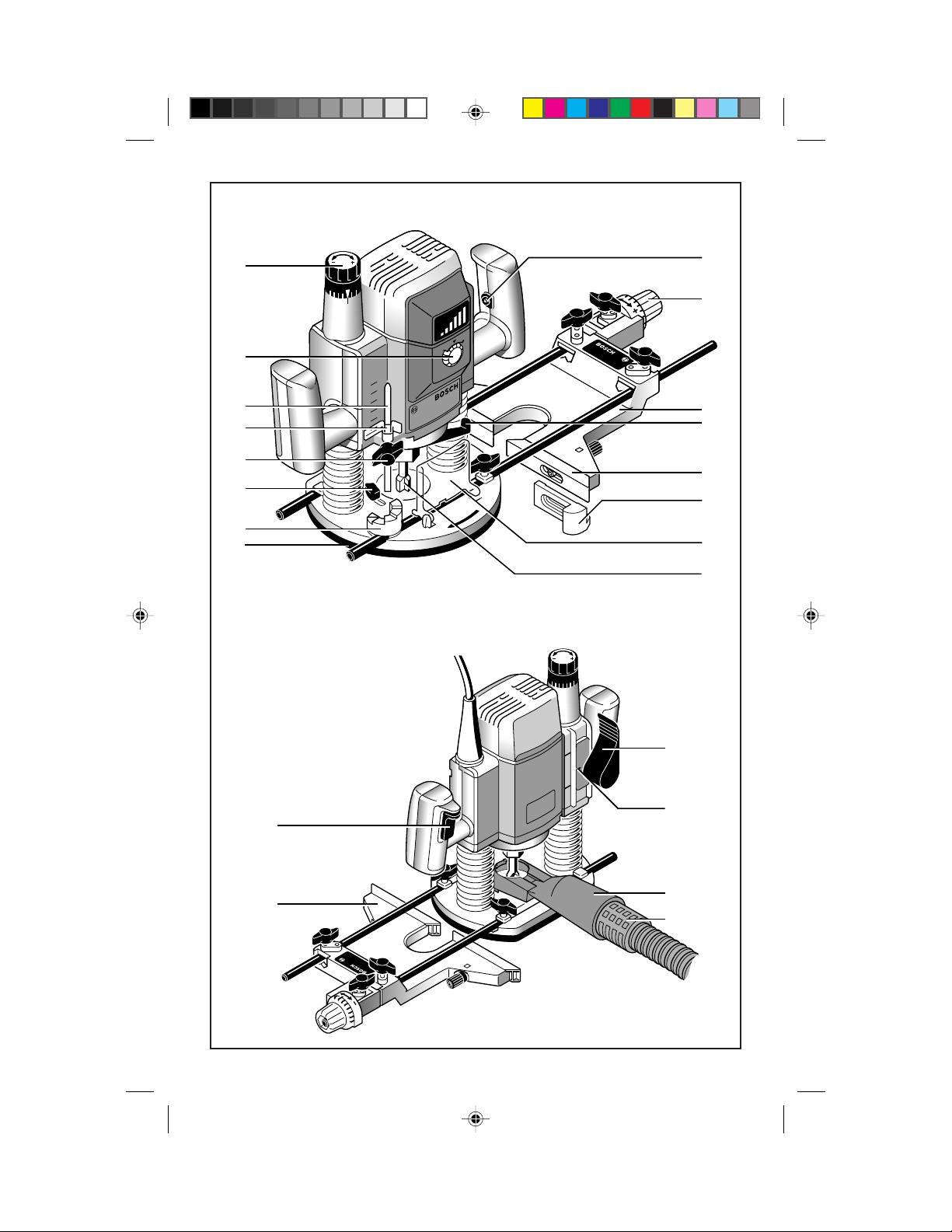
Router Components
1. Fine adjust knob 14. Chip deflector
2. Variable speed dial (1613EVS & 1614EVS) 15. Subbase
3. Depth indicator rod 16. Plunge lock/release lever
4. Depth indicator 17. Index marker
5. Depth indicator lock/release knob 18. Trigger switch
6. Templet guide lock/release lever 19. Vacuum attachment
7. Revolving depth turret 20. Vacuum hose
8. "Lock-ON" button 21. Retaining ring
9. Router guide adustment knob 22. Collet
10. Deluxe router guide 23. Collet nut
11. Spindle lock 24. Templet guide
12. Guide plate 25. Collet chuck assembly
13. Guide plate 26. Router bit
27. Template pattern
(NOTE: Router components not illustrated on page 2 are illustrated elsewhere in this manual)
3
BM 2610967928 1/97 12/7/98, 10:29 AM3

WARNING! “READ ALL INSTRUC-
TIONS”. Failure to follow the SAFETY RULES
identified by the BULLET (•) symbols listed
BELOW and other safety precautions, may
result in serious personal injury. Keep these
operating instructions with this product.
GENERAL SAFETY RULES
for all Power Tools
Work Area
• KEEP WORK AREAS CLEAN. Cluttered
areas and benches invite accidents.
• AVOID DANGEROUS ENVIRONMENT.
Don’t use power tools in damp or wet locations.
Do not expose power tools to rain. Keep work
area well lit.
• AVOID GASEOUS AREAS. Do not operate portable electric tools in explosive atmospheres in presence of flammable liquids or
gases. Motors in these tools normally spark,
and the sparks might ignite fumes.
• KEEP CHILDREN AWAY. Do not let
visitors contact tool or extension cord. All
visitors should be kept away from work areas.
Personal Safety
• GUARD AGAINST ELECTRIC SHOCK.
Prevent body contact with grounded surfaces
such as pipes, radiators, ranges and refrigerator
enclosures. Rubber gloves and non-skid footwear are recommended when working outdoors, where damp or wet ground may be
encountered. A Ground Fault Circuit Interrupter protected power line must be used for
these conditions.
• DRESS PROPERLY. Do not wear loose
clothing or jewelry. They can be caught in
moving parts. Wear protective hair covering to
contain long hair.
• USE SAFETY EQUIPMENT. WEAR
SAFETY GOGGLES or glasses with side
shields. Wear hearing protection during extended use of power tools and dust mask for
dusty operations.
• STAY ALERT. USE COMMON SENSE.
Watch what you are doing. Do not operate tool
when you are tired or under influence of drugs.
•
REMOVE ADJUSTING KEYS AND
WRENCHES.
keys and adjusting wrenches are removed from
Form habit of checking to see that
tool before turning it on.
• AVOID ACCIDENTAL STARTING. Don’t
carry plugged in tool with finger on switch. Be
sure the switch is OFF before being plugged in.
• DON’T OVERREACH. Keep proper footing and balance at all times.
• BEFORE CONNECTING THE TOOL to a
power supply (receptacle, outlet, etc.) be sure
the voltage supplied is the same as that specified on the tool’s nameplate. A power supply
with voltage greater than that specified for the
tool can result in serious injury to the user - as
well as damage to the tool. If in doubt, DO NOT
PLUG IN THE TOOL. Using a power supply
with voltage less than the nameplate rating is
harmful to the motor.
“Volts AC” designated tools are for Alternating
Current 50-60 Hz only. “Volts DC” designated
tools are for Direct Current. Do not use AC
designated tools with DC power supply. Do not
use electronic speed controlled tools with DC
power supply.
Tool Use and Care
• DON’T FORCE TOOL. It will do the job
better and safer at the rate for which it was
designed.
• USE RIGHT TOOL. Don’t force small tool
or attachment to do the job of a heavy-duty tool.
Don’t use tool for purpose not intended - for
example; don’t use a circular saw for cutting
tree limbs or logs.
• SECURE WORK. Use clamps or a vise to
hold work. It’s safer than using your hand and
it frees both hands to operate the tool.
• DON’T ABUSE CORD. Never carry tool by
cord or yank it to disconnect from receptacle.
Keep cord from heat, oil, and sharp edges.
Always keep cord away from the spinning
blade, bits or any other moving part while the
tool is in use.
• OUTDOOR USE EXTENSION CORDS.
When tool is used outdoors, use only extension
cords suitable for use outdoors and marked with
suffix W-A (for UL), or W (for CSA). Refer to
section “Extension Cords”, for proper cord use.
• DISCONNECT TOOLS. When not in use,
before servicing, or when changing blades,
bits, cutters, etc.
• STORE IDLE TOOLS. When not in use,
tools should be stored in dry, high or locked up
place - out of the reach of children.
4
BM 2610967928 1/97 12/7/98, 10:29 AM4

• DO NOT ALTER OR MISUSE TOOL.
These tools are precision built. Any alterations
or modifications not specified is misuse and
may result in a dangerous condition.
• THE USE OF ANY ACCESSORIES not
specified in this manual may create a hazard.
• MAINTAIN TOOLS WITH CARE. Keep
tools sharp and clean for better and safer performance. Follow instructions for lubricating and
changing accessories. Inspect tool cords periodically and if damaged, have repaired by authorized service facility. Inspect extension
cords periodically and replace if damaged. Keep
handles dry, clean and free from oil and grease.
• CHECK DAMAGED PARTS. Before further use of the tool, a guard or other part that is
damaged should be carefully checked to determine that it will operate properly and perform
its intended function. Check for alignment of
moving parts, binding of moving parts, breakage of parts, mounting, and any other conditions that may affect its operation. A guard or
other part that is damaged should be promptly
and properly repaired or replaced. Have defective switches replaced. Do not use tool if switch
does not turn it on or off.
• ALL REPAIRS, ELECTRICAL OR MECHANICAL, should be attempted only by
trained repairmen. Contact the nearest Bosch
Factory Service Center, or Bosch Authorized
Service Center or other competent repair center. Use only Bosch replacement parts, any
other may create a hazard.
Safety Rules for Routers
• If router bit is protruding through the base,
never lay the router down until the motor has
come to a complete standstill.
• Never hold the workpiece in one hand and
the router in other when in use. Always clamp
the material and hold the router securely with
both hands.
• Never use bits that have a cutting diameter
greater than the opening in the base.
• After changing the bits or making any adjustments, make sure the collet nut and any other
adjustment devices are securely tightened before using the router.
• The direction of feeding the router into the
material is very important and it relates to the
direction of bit rotation. When viewing the
router from the top, the bit rotates clockwise.
When the router is located between your body
and the material, the feed direction must be to
the right. If the material is located between your
body and the router, then the feed direction
must be to the left. Feeding the router in the
wrong direction causes the cutting edge of the
bit to climb out of the work and pull the router
in the direction of this feed.
Double Insulated Tools
• Double Insulation is a design concept
used in electric power tools which eliminates
the need for the three wire grounded power cord
and grounded power supply system. It is a
recognized and approved system by
Underwriter’s Laboratories, CSA and Federal
OSHA authorities.
• Never start the router when the bit is engaged
in the material. The bit’s cutting edge may grab
the material causing the router to get out of
control. Always hold the router with two hands
during start-up. The reaction torque of the
motor can cause the router to twist.
• Always make sure the workpiece is free from
nails and other foreign objects which can cause
the bit and router to jump and damage the bit.
• Always wear safety goggles. If router has a
removable chip deflector, keep it in place when
routing.
• Never touch the router bit or other moving
part during use. After use the router bit is too
hot to be touched by bare hands.
BM 2610967928 1/97 12/7/98, 10:29 AM5
IMPORTANT: Servicing of a tool with
double insulation requires care and knowledge
of the system and should be performed only by
a qualified service technician. WHEN SERVICE IS REQUIRED USE ONLY IDENTICAL REPLACEMENT PARTS.
POLARIZED PLUGS: If your tool is equipped
with a polarized plug (one blade is wider than
the other), this plug will fit in a polarized outlet
only one way. If the plug does not fit fully in the
outlet, reverse the plug. If it still does not fit,
contact a qualified electrician to install the
proper outlet. To reduce the risk of electric
shock do not change the plug in any way.
5
Extension Cords
• Replace damaged cords immediately. Use of
damaged cords can shock, burn or electrocute.
• If an extension cord is necessary, a cord with
adequate size conductors should be used to
prevent excessive voltage drop, loss of power
or overheating. The table below shows the
correct size to use, depending on cord length
and amperage rating on the tool’s nameplate. If
in doubt, use the next heavier gauge. Always
use U.L. and CSA listed extension cords.
Ampere Rating (shown on nameplate)
0- 2.1- 3.5- 5.1- 7.1- 12.1-
2.0 3.4 5.0 7.0 12.0 16.0
25' 18 18 18 18 16 14
50' 18 18 16 16 14 12
75' 18 18 16 14 12 10
100' 18 16 14 12 10
Cord Length
150' 16 14 12 12 Wire Gauge
Note: The smaller the gauge number, the larger
the wire is in the cord.
"SAVE THESE INSTRUCTIONS"
Operating the Tool
Variable Speed with Dial Setting
(1613EVS & 1614EVS)
Your router is also equipped with a variable
speed dial 2. The router bit speed can be preset
from 12,000 to maximum nameplate RPM by
rotating the dial to the desired setting. The dial
may be set on or between any of six positions (1
= low through 6 = high). The "Lock-ON"
button may also be used with any setting of the
dial.
The following speeds generally apply, but precise settings are largely determined by
experience with the material being cut. Momentary speed variation is normal when starting
the router until the electronic regulator takes
control.
Dial 1613EVS 1614EVS
Setting RPM RPM Material
1 12,000 12,000 nonferrous metals,
2 14,000 14,500 larger diameter router
3 16,000 17,000 bits and cutters.
4 18,000 19,500 Softwoods, plastics,
5 20,000 22,000 counter tops, smaller
6 22,000 23,000 diameter router bits
and cutters.
"Soft Start" Feature
(1613EVS & 1614EVS )
The router is equipped with the "soft start"
feature which gradually increases the starting
speed and torque, reducing the stress that occurs from a high torque start.
Trigger Switch with "Lock-ON"button
Your tool can be turned "ON" or "OFF" by
squeezing or releasing the trigger. Your tool is
also equipped with "Lock-ON" button, located
on the left side of the trigger handle, that allows
for continuous operation without holding the
trigger.
TO LOCK SWITCH "ON": Squeeze trigger,
depress button and release trigger.
TO UNLOCK THE SWITCH: Squeeze trigger
and release it without depressing the "LockON" button.
WARNING! If the "Lock-ON" button is con-
tinuously being depressed, the trigger cannot
be released.
BM 2610967928 1/97 12/7/98, 10:29 AM6
Start the tool before applying to work and let
the tool come to full speed before contacting
the workpiece. Lift the tool from the work
before releasing the switch. DO NOT turn the
switch "ON" and "OFF" while the tool is under
load; this will greatly decrease the switch life.
Router Bit Installation and Removal
WARNING! Always disconnect the tool
from the power supply before installing router
bits, accessories or making any adjustments.
Installing a Router Bit
Turn the armature shaft to align the flats with
the spindle lock 11, and press the spindle lock
firmly down to engage it. Next, use the wrench
supplied to loosen the collet chuck assembly.
Insert the shank of the router bit into the collet
chuck as far as it will go, then back the shank
6

out until the cutters are approximately 1/8" to
1/4" away from the collet chuck face. With the
router bit inserted and the spindle lock fully
engaged, tighten the collet chuck assembly
firmly in a clockwise direction, (viewed from
under the router), with the wrench supplied. To
avoid damaging the collet chuck, never tighten
the collet chuck unless a router bit of proper
shank size is inserted into the collet.
To ensure proper gripping of the router bit and
minimize run-out, the shank of the router bit
should always be inserted at least 5/8".
CAUTION! To prevent damage to tool. Do
not tighten collet without a bit. NOTE: The bit
shank and chuck should be clean and free of
dust, wood, residue and grease before assembling.
CAUTION! Do not use router bits greater
than 1-5/8" in diameter as they will not fit
through the base casting.
Removing the Router Bit
Use the spindle lock and wrench as described
above, and turn the collet chuck assembly in a
counter-clockwise direction. Once the collet
chuck assembly is loosened, continue to turn
the collet chuck until it pulls the collet free
from its taper, and the router bit can be removed.
NOTE: The collet chuck is self-extracting; it is
NOT necessary to strike the collet chuck to free
the bit.
Collet Chuck Care
With the router bit removed, continue to turn
the collet chuck counter-clockwise until it is
free of the shaft. To assure a firm grip, occasionally blow out the collet chuck with compressed air, and clean the taper in the armature
assembly shaft with a tissue or fine brush. The
collet chuck is made up of three component
parts as illustrated;
check to see that the retaining ring 21 is properly located around the
collet 22 and seated in
the inner groove of the
collet chuck nut 23 and
21
22
25
23
lightly thread the collet chuck back onto the
armature shaft. Replace worn or damaged
collet chucks immediately.
Plunge Mechanism
To release the plunge mechanism, grasp the
router handles firmly with both hands and press
the plunge lock/release lever 16 with the thumb
of the left hand. The motor may then be raised
or lowered to the desired position. The plunge
lock/release lever is spring-loaded, and will
hold the router motor in position when pressure
on the lock lever is released. When plunging,
always apply uniform firm pressure to both
handles to avoid cocking the motor on the
posts.
Indicator Rod and Turret
The depth indicator rod 3 and the revolving
depth turret 7 are used to control cutting depth
as follows;
With the bit installed, gently lower the motor
until the tip of the router bit just contacts the
level surface the router is sitting on. This is the
“zero” position, from which further depth adjustments can be accurately made. To set a
desired depth of cut, rotate revolving depth
turret until the lowest step is aligned with the
depth indicator rod. Loosen depth indicator
lock/release knob 5 and lower the depth indicator rod until it contacts the lowest step of the
turret. Slide the depth indicator 4 until the red
line indicates zero on the depth scale, indicating
the point at which the bit just contacts the work.
To set a desired cutting depth, slide the depth
indicator rod up until the red depth indicator
line attains the desired cutting depth, and secure the rod in position by firmly tightening the
depth indicator lock/release knob. The desired
depth of cut may now be achieved by plunging
the router until the depth indicator rod contacts
the selected stop on the revolving depth turret.
To be certain that your depth settings are accurate, you may want to make test cuts in scrap
material before beginning work. Once the desired final depth has been set on the lowest
depth turret setting with the depth indicator
rod, it is possible to make progressively deeper
cuts by starting with a higher flat on the depth
turret and after each cut, rotating the revolving
7
BM 2610967928 1/97 12/7/98, 10:29 AM7
depth turret to progressively lower stops as
desired, until the final depth (lowest step or
flat) is reached.
Fine adjustment
The router is equipped with a true micrometertype fine adjustment mechanism, which can be
used in any plunge position and provides precise adjustment of the router bit position for
unmatched accuracy. When the tool is plunged
to the approximate position desired, this device
may be adjusted to precisely set the final cutter
position.
To use the fine adjustment, turn the fine adjust
knob 1 clockwise to lower the router bit or
counter-clockwise to raise it, as indicated by
the arrow molded into the top of the knob. To
allow precise settings, the indicator ring is
graduated in English and Metric increments,
and each line is equal to 1/10 mm or .004". The
indicator ring may be reset to zero without
moving the fine-adjust knob, to allow the user
to begin the adjustment from any reference
point desired.
The fine adjustment mechanism has a total
adjustment range of 5/8", which is indicated by
the two lines printed on back of the housing.
Whenever the fine adjustment is used, be certain that the index marker 17 is positioned
between these two lines to ensure that there will
be enough travel in the desired direction after
the router is plunged into position. Note that
when the router is plunged to maximum depth
or is fully retracted to the top of the posts, the
fine adjustment mechanism will not move the
motor further down or up, as the full extension
of the travel has been reached at these points.
Similarly, the fine adjustment cannot lower the
bit when the depth indicator rod is tightened
against the depth turret.
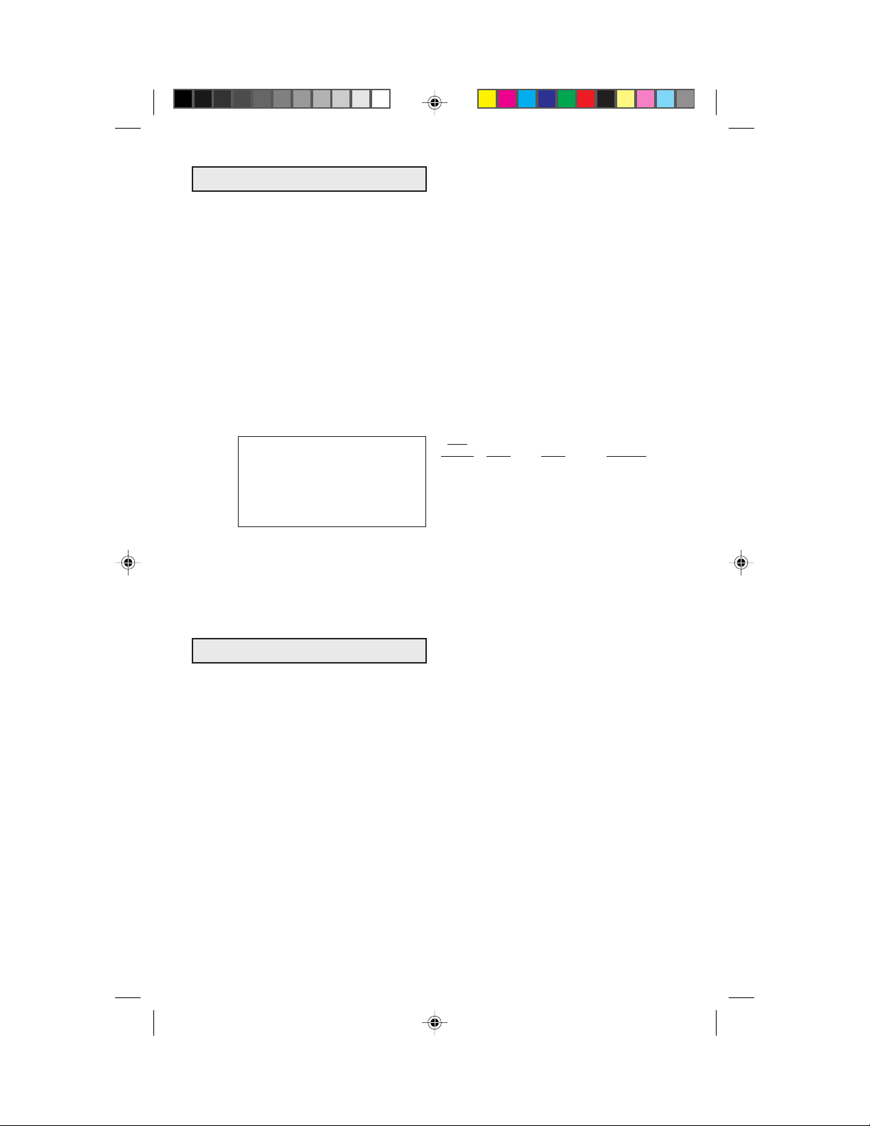
Direction of Feed
The router rotates in a clockwise direction, as
viewed from the top of the router. The correct
relationship between direction of router bit or
cutter rotation and router feed is shown below.
It is very important to move the router in the
proper direction or router bit chatter and rough
cutting will be the result. As an example, to
rout a decorative edge on the front of a table top,
you would move the router from left to right to
perform the operation, or counter-clockwise
around the workpiece. If you were cutting an
opening in the center of a panel, you would feed
the router in a clockwise direction, so that the
edge of the opening would be cut against the
rotation of the router bit as described, and have
a smooth finish. Whenever you are cutting
completely around a workpiece, it is advisable
to cut across the grain first, so any corner
tearout may be smoothed by cutting with the
grain on the second pass.
WORK
CUTTER
DIRECTION
OF FEED
Rate of Feed
When routing or doing related work in wood
and plastics, the best finishes will result if the
depth of cut and feed rate are regulated to keep
the motor operating at high speed. Feed the
router at a moderate rate. Soft materials require
a faster feed rate than hard materials.
The router may stall if improperly used or
overloaded. Reduce the feed rate to prevent
possible damage to the tool. Always be sure the
collet nut is tightened securely before use.
Always use router bits with the shortest cutting
length necessary to produce the desired cut.
This will minimize router bit run-out and chatter.
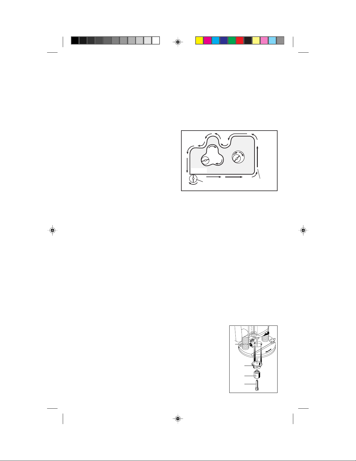
Templet Guides
The router is equipped with an exclusive quickchange templet guide mechanism, which firmly
grips the guides with a spring-loaded ring built
into the base. To insert or change the
templet guide 24, retract the templet
6
guide lock/release
lever 6. Align any
two of the four cutaway tabs on the
templet guide to the
two cast-in bosses in
the templet guide re-
24
23
26
cess of the base.
8
BM 2610967928 1/97 12/7/98, 10:29 AM8
Insert the templet guide and release the lock
lever to grip the templet guide in place.
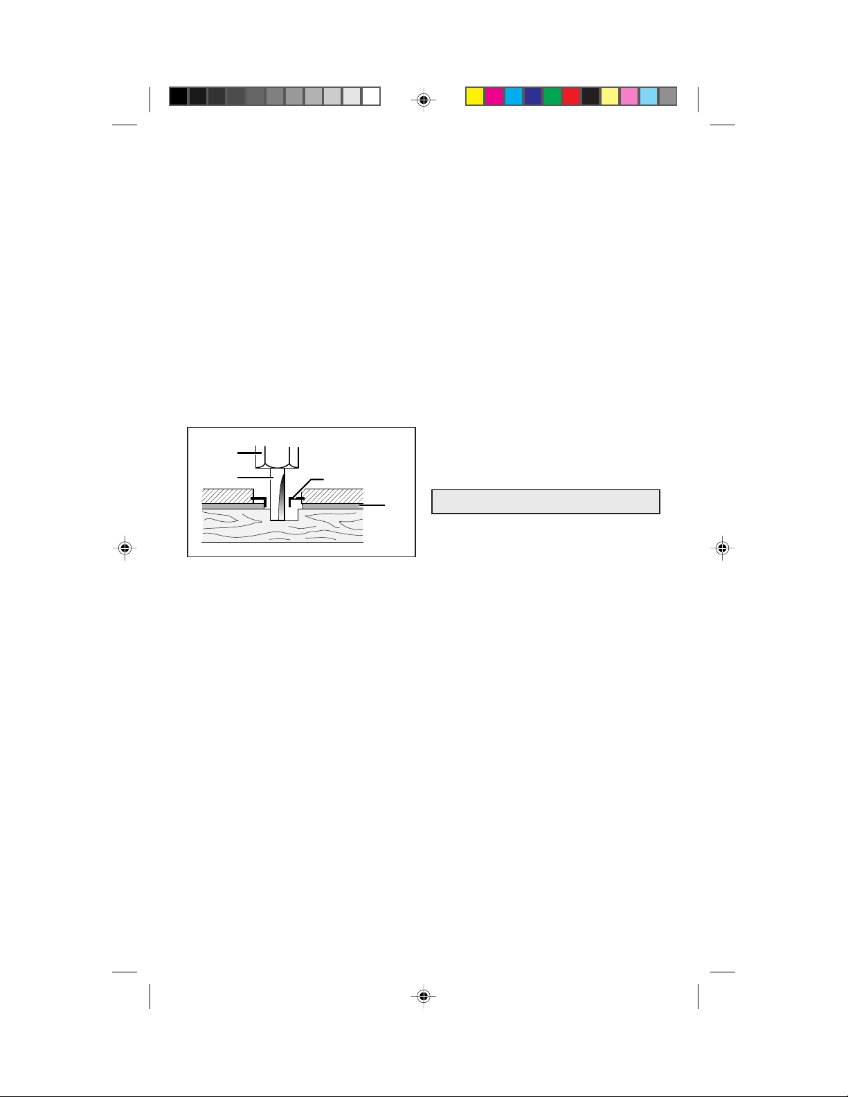
Templet guides are used with a number of
special accessories, such as hinge templets and
dovetail fixtures which are listed in your
BOSCH catalog. In addition, special templets
are easily prepared for cutting repeated patterns, special designs, inlays, and other
applications. A templet pattern may be made of
plywood, hardboard, metal or even plastic, and
the design can be cut with a router, jigsaw, or
other suitable cutting tool. Remember that the
pattern will have to be made to compensate for
the distance between the router bit and the
templet guide 24, as the final workpiece will
differ in size from the templet pattern 27 by that
amount, due to the cutter position.
23
26
24
27
Deluxe Router Guide
For routing operations such as grooving or
dadoing, it is often necessary to guide the tool
in a line parallel to a straight edge. One method
of obtaining a straight cut is to securely clamp
a board or other straightedge to the work surface, and guide the edge of the router sub-base
along this path. It is best to keep the router in one
position as it is moved along the guide, as this
will produce the straightest cut.
The Bosch deluxe router guide is an accessory
that will guide the router parallel to a straight
edge or around a curved surface. The deluxe
router guide is supplied with two rods and a
series of wing nuts and screws to fasten the
guide and adjust its position relative to the bit.
With the guide installed and adjusted, the router
should be fed normally, keeping the guide in
contact with the edge of the workpiece at all
times. The deluxe router guide may also be
positioned under the router base for operations
where a limited amount of bit exposure is desired.
The Bosch deluxe router guide includes a
fine-adjustment mechanism for extra precision,
and removable face plates for guiding the router
along straight or curved surfaces. For proper
operation, please refer to the instructions which
are included with this accessory.
Chip Extraction
Your router may be fitted with optional chip
extraction accessories, which are available from
your Bosch dealer. Chip extraction is most
effective on grooving, dadoing, and other flatsurface operations where flying chips can be
controlled. It is less effective on edge forming
or when template guides are used as the vacuum
efficiency is greatly diminished in such circumstances.
WARNING! Use of any accessory not speci-
fied in this manual or the BOSCH catalog for
use with this tool may create a hazard.
Maintenance and Service
WARNING! Preventive maintenance per-
formed by unauthorized personnel may result
in misplacing of internal wires and components
which could cause serious hazard. We recommend that all tool service be performed at a
Bosch Factory Service Center.
Tool Lubrication
Your Bosch tool has been properly lubricated
and is ready for use. We recommend, that tools
with gears be regreased with a special gear
lubricant every time the brushes are changed.
Carbon Brushes
The brushes and commutator in your Bosch
tool have been engineered for many hours of
dependable service. To maintain peak efficiency of the motor, we recommend that every
two to six months the brushes be examined.
Only genuine Bosch replacement brushes specially designed for your tool should be used.
Bearings
After about 300-400 hours of operation, or at
every second brush change, the bearings should
be replaced at a Bosch Factory Service Center.
Bearings which become noisy (due to heavy
load or very abrasive material cutting) should
be replaced at once to avoid overheating and
motor failure.
9
BM 2610967928 1/97 12/7/98, 10:29 AM9
 Loading...