


Operating/Safety Instructions
Consignes de fonctionnement/sécurité
Instrucciones de funcionamiento
y seguridad
IMPORTANT: IMPORTANT : IMPORTANTE:
Read Before Using Lire avant usage Leer antes de usar
For English Parlez-vous français? ¿Habla español?
See page 2 Voir page 11 Ver página 20
Consumer Information
Renseignement des consommateurs
Información para el consumidor
Toll Free Number: Appel gratuit : Número de teléfono gratuito:
1-877-BOSCH99 (1-877-267-2499) http://www.boschtools.com.
1581AVS
BM 2610991830 1/02 1/21/02 12:20 PM Page 1

-2-
Work Area
Keep your work area clean and well lit.
Cluttered benches and dark areas invite
accidents.
Do not operate power tools in explosive
atmospheres, such as in the presence of
flammable liquids, gases, or dust. Power
tools create sparks which may ignite the dust
or fumes.
Keep by-standers, children, and visitors
away while operating a power tool.
Distractions can cause you to lose control.
Electrical Safety
Double Insulated tools are equipped with a
polarized plug (one blade is wider than the
other.) This plug will fit in a polarized outlet
only one way. If the plug does not fit fully in
the outlet, reverse the plug. If it still does
not fit, contact a qualified electrician to
install a polarized outlet. Do not change
the plug in any way. Double Insulation
eliminates the need for the three wire
grounded power cord and grounded power
supply system. Before plugging in the tool, be
certain the outlet voltage supplied is within the
voltage marked on the nameplate. Do not use
“AC only” rated tools with a DC power supply.
Avoid body contact with grounded surfaces
such as pipes, radiators, ranges and
refrigerators. There is an increased risk of
electric shock if your body is grounded. If
operating the power tool in damp locations is
unavoidable, a Ground Fault Circuit Interrupter
must be used to supply the power to your tool.
Electrician’s rubber gloves and footwear will
further enhance your personal safety.
Don't expose power tools to rain or wet
conditions. Water entering a power tool will
increase the risk of electric shock.
Do not abuse the cord. Never use the cord
to carry the tools or pull the plug from an
outlet. Keep cord away from heat, oil, sharp
edges or moving parts. Replace damaged
cords immediately. Damaged cords increase
the risk of electric shock.
When operating a power tool outside, use
an outdoor extension cord marked "W-A"
or "W." These cords are rated for outdoor use
and reduce the risk of electric shock. Refer to
“Recommended sizes of Extension Cords” in
the Accessory section of this manual.
Personal Safety
Stay alert, watch what you are doing and
use common sense when operating a
power tool. Do not use tool while tired or
under the influence of drugs, alcohol, or
medication. A moment of inattention while
operating power tools may result in serious
personal injury.
Dress properly. Do not wear loose clothing
or jewelry. Contain long hair. Keep your
hair, clothing, and gloves away from
moving parts. Loose clothes, jewelry, or long
hair can be caught in moving parts. Keep
handles dry, clean and free from oil and
grease.
Avoid accidental starting. Be sure switch is
“OFF” before plugging in. Carrying tools
with your finger on the switch or plugging in
tools that have the switch “ON” invites
accidents.
Remove adjusting keys or wrenches before
turning the tool “ON”. A wrench or a key
that is left attached to a rotating part of the
tool may result in personal injury.
Do not overreach. Keep proper footing and
balance at all times. Proper footing and
balance enables better control of the tool in
unexpected situations.
Use safety equipment. Always wear eye
protection. Dust mask, non-skid safety
shoes, hard hat, or hearing protection must be
used for appropriate conditions.
Tool Use and Care
Use clamps or other practical way to
secure and support the workpiece to a
stable platform. Holding the work by hand or
against your body is unstable and may lead to
loss of control.
Do not force tool. Use the correct tool for
your application. The correct tool will do the
job better and safer at the rate for which it is
designed.
Read and understand all instructions. Failure to follow all instructions
listed below, may result in electric shock, fire and/or serious personal injury.
SAVE THESE INSTRUCTIONS
!
WARNING
Power Tool Safety Rules
BM 2610991830 1/02 1/21/02 12:20 PM Page 2

-3-
Safety Rules for Jigsaws
Hold tool by insulated gripping surfaces
when performing an operation where the
cutting tool may contact hidden wiring or
its own cord. Contact with a "live" wire will
make exposed metal parts of the tool "live"
and shock the operator. Do not drill, fasten
or break into existing walls or other blind
areas where electrical wiring may exist. If
this situation is unavoidable, disconnect all
fuses or circuit breakers feeding this
worksite.
Never leave the trigger locked "ON".
Before plugging the tool in, check that the
trigger lock is "OFF". Accidental start-ups
could cause injury.
Be aware of the location and setting of
the switch "Lock-ON" button. If the switch
is locked "ON" during the use, be ready for
emergency situations to switch it "OFF", by
first pulling the trigger then immediately
releasing it without pressing the "Lock-ON"
button.
Keep hands away from cutting area. Do
not reach under the material being cut.
The proximity of the blade to your hand is
hidden from your sight.
Keep hands from between the gear
housing and saw blade holder. The
reciprocating blade holder can pinch your
fingers.
Do not use dull or damaged blades. Bent
blade can break easily or cause kickback.
Before starting to cut, turn tool "ON" and
allow the blade to come to full speed.
Tool can chatter or vibrate if blade speed is
too slow at beginning of cut and possibly
kickback.
Always wear safety goggles or eye
protection when using this tool. Use a
dust mask or respirator for applications
which generate dust.
Secure material before cutting. Never
hold it in your hand or across legs. Small
Do not use tool if switch does not turn it
“ON” or “OFF”. Any tool that cannot be
controlled with the switch is dangerous and
must be repaired.
Disconnect the plug from the power
source before making any adjustments,
changing accessories, or storing the tool.
Such preventive safety measures reduce the
risk of starting the tool accidentally.
Store idle tools out of reach of children
and other untrained persons. Tools are
dangerous in the hands of untrained users.
Maintain tools with care. Keep cutting
tools sharp and clean. Properly
maintained tools, with sharp cutting edges
are less likely to bind and are easier to
control. Any alteration or modification is a
misuse and may result in a dangerous
condition.
Check for misalignment or binding of
moving parts, breakage of parts, and any
other condition that may affect the tools
operation. If damaged, have the tool
serviced before using. Many accidents are
caused by poorly maintained tools. Develop
a periodic maintenance schedule for your
tool.
Use only accessories that are
recommended by the manufacturer for
your model. Accessories that may be
suitable for one tool, may become
hazardous when used on another tool.
Service
Tool service must be performed only by
qualified repair personnel. Service or
maintenance performed by unqualified
personnel could result in a risk of injury. For
example: internal wires may be misplaced or
pinched, safety guard return springs may be
improperly mounted.
When servicing a tool, use only identical
replacement parts. Follow instructions in
the Maintenance section of this manual.
Use of unauthorized parts or failure to follow
Maintenance Instructions may create a risk
of electric shock or injury. Certain cleaning
agents such as gasoline, carbon
tetrachloride, ammonia, etc. may damage
plastic parts.
BM 2610991830 1/02 1/21/02 12:20 PM Page 3

-4-
or thin material may flex or vibrate with the
blade, causing loss of control.
Make certain all adjusting screws and the
blade holder are tight before making a
cut. Loose adjusting screws and holders
can cause the tool or blade to slip and loss
of control may result.
When removing the blade from the tool
avoid contact with skin and use proper
protective gloves when grasping the
blade or accessory. Accessories may be
hot after prolonged use.
If your tool is equipped with a dust bag,
empty it frequently and after completion of
sawing. Spontaneous combustion, may in
time, result from mixture of oil or water with
dust particles. Be extremely careful of dust
disposal, materials in fine particle form may be
explosive. Do not throw contents on an open
fire.
Some dust created by
power sanding, sawing,
grinding, drilling, and other construction
activities contains chemicals known to
cause cancer, birth defects or other
reproductive harm. Some examples of
these chemicals are:
• Lead from lead-based paints,
• Crystalline silica from bricks and cement
and other masonry products, and
• Arsenic and chromium from chemically-
treated lumber.
Your risk from these exposures varies,
depending on how often you do this type of
work. To reduce your exposure to these
chemicals: work in a well ventilated area,
and work with approved safety equipment,
such as those dust masks that are specially
designed to filter out microscopic particles.
!
WARNING
BM 2610991830 1/02 1/21/02 12:20 PM Page 4
-5-
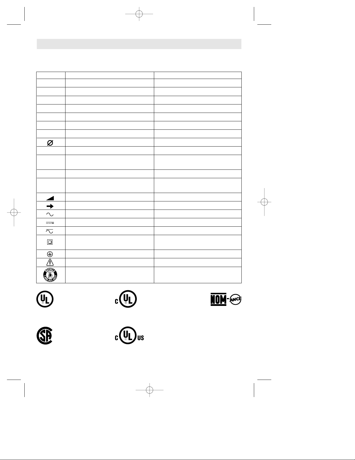
IMPORTANT: Some of the following symbols may be used on your tool. Please study them
and learn their meaning. Proper interpretation of these symbols will allow you to operate the
tool better and safer.
Symbol Name Designation/Explanation
V Volts Voltage (potential)
A Amperes Current
Hz Hertz Frequency (cycles per second)
W Watt Power
kg Kilograms Weight
min Minutes Time
s Seconds Time
Diameter Size of drill bits, grinding wheels, etc.
n
0
No load speed Rotational speed, at no load
.../min Revolutions or reciprocation per minute Revolutions, strokes, surface speed,
orbits etc. per minute
0 Off position Zero speed, zero torque...
1, 2, 3, ... Selector settings Speed, torque or position settings.
I, II, III, Higher number means greater speed
Infinitely variable selector with off Speed is increasing from 0 setting
Arrow Action in the direction of arrow
Alternating current Type or a characteristic of current
Direct current Type or a characteristic of current
Alternating or direct current Type or a characteristic of current
Class II construction Designates Double Insulated
Construction tools.
Earthing terminal Grounding terminal
Warning symbol Alerts user to warning messages
Ni-Cad RBRC seal Designates Ni-Cad battery recycling
program
Symbols
0
This symbol designates
that this tool is listed by
Underwriters Laboratories.
This symbol designates
that this tool is listed by
the Canadian Standards
Association.
This symbol designates
that this tool is listed to
Canadian Standards by
Underwriters Laboratories.
This symbol
designates
that
this tool
complies
to NOM
Mexican
Standards.
This symbol designates
that this tool is listed by
Underwriters Laboratories,
and listed to Canadian
Standards by Underwriters
Laboratories.
BM 2610991830 1/02 1/21/02 12:20 PM Page 5
-6-
Functional Description and Specifications
Disconnect the plug from the power source before making any
assembly, adjustments or changing accessories. Such preventive safety
measures reduce the risk of starting the tool accidentally.
!
WARNING
Jigsaws
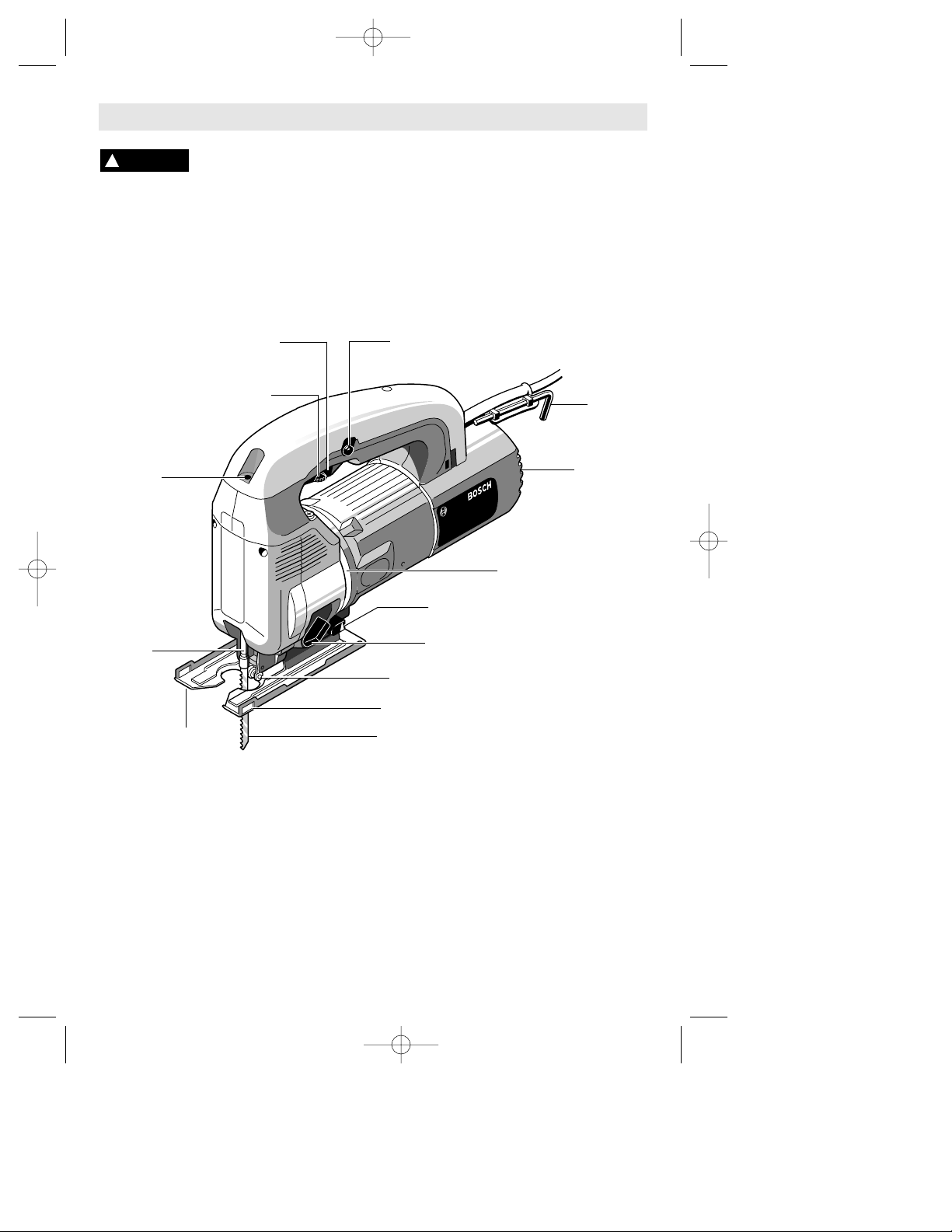
Maximum capacities:
Material Size
Wood 2-3/8" (60mm)
Plastic 1-1/4" (32mm)
Aluminum 3/4" (20mm)
Non-ferrous metal 3/4" (20mm)
Mild steel 3/8" (10mm)
Stainless steel 1/8" (3mm)
Alloy steel 1/8" (3mm)
TOP
PLUNGER
HOLE
"LOCK-ON" BUTTON
TRIGGER PRESET SPEED
ADJUSTING DIAL
TRIGGER SWITCH
ALLEN
WRENCH
5 MM
VENTILATION
OPENINGS
CHIP BLOWER LEVER
BLADE ROLLER GUIDE
BLADE ORBIT SELECTOR LEVER
CUTTING GUIDE SLOTS
BLADE
BLADE
PLUNGER
BASE
VENTILATION
OPENINGS
BM 2610991830 1/02 1/21/02 12:20 PM Page 6
-7-
Assembly
VARIABLE SPEED CONTROLLED
TRIGGER SWITCH
Your tool is equipped with a variable speed
trigger switch. The tool can be turned "ON" or
"OFF" by squeezing or releasing the trigger. The
speed can be adjusted from the minimum to
maximum nameplate RPM by the pressure you
apply to the trigger. Apply more pressure to
increase the speed and release pressure to
decrease speed.
"LOCK-ON" BUTTON
The "Lock-ON" button, located in the handle
of your tool allows for continuous operation at
maximum RPM without holding the trigger.
TO LOCK TRIGGER "ON": squeeze trigger,
depress button and release trigger.
TO UNLOCK THE TRIGGER: squeeze trigger
and release it without depressing the "LockON" button.
If the “Lock-ON” button is
continuously being depressed,
the trigger can not be released.
TRIGGER PRESET SPEED
ADJUSTING DIAL
This feature enables you to preset the trigger
at desired speeds by rotating the dial on the
trigger to a higher or lower setting. Regardless
of the the pressure applied on trigger, the tool
will not operate any faster that the maximum
speed setting selected.
Setting
A-B Low stroke
C-D Medium stroke
E High stroke
PLUNGER SPEED
The jigsaw cutting speed or stroke rate
required depends on the material being cut,
the type of blade used, and the feed rate
preferred by the operator. The best speed for
a particular application is largely determined by
experience, though as a general rule, slower
speeds are for denser materials and faster
speeds for soft materials. Note that when the
jigsaw is used at low speed settings for any
length of time, the motor temperature will rise
due to the slower speed of the internal cooling
fan. In such cases, it is necessary to
occasionally run the tool at full speed for a few
minutes to keep the motor operating at high
efficiency.
BLADE ORBIT
Maximum cutting efficiency can be obtained
by adjusting the blade orbit selector lever to
suit the material being cut. The following chart
will help you determine which setting to use for
your application. This chart is intended as a
guideline only, and test cuts in scrap material
should be performed first to determine the
best setting.
Setting O hard materials such as metals
or thin sheet metals and used
with knife blades, grit edge
blades or rasp work
Setting I soft materials where cleaner
cutting or delicate scrolling
work is performed
Setting II medium density materials
such as harder woods or
particle board
Setting III soft materials such as wood,
plastics, etc.
Operating Instructions
BLADE INSTALLATION
Set the blade orbit selector lever to position III.
Fit the supplied screwdriver into the top
plunger hole and loosen the internal blade
securing screw about 3 to 4 turns counterclockwise.
Insert the blade into blade plunger at a 90˚
angle to the cutting direction. With a slight
upward pressure, turn the blade teeth forward
(direction of cut) and guide the back of the
blade into the groove in the center of blade
roller guide. Pull gently down on the blade to
seat the blade tabs in the plunger.
With the blade in the proper position, securely
tighten the blade screw by turning the
screwdriver clockwise.
Removing the blade is essentially the reverse
of the installation procedure, however, take
note that once the blade screw is loosened,
gently push the blade upward to release the
blade tabs from the plunger.
!
WARNING
BM 2610991830 1/02 1/21/02 12:20 PM Page 7
-8-
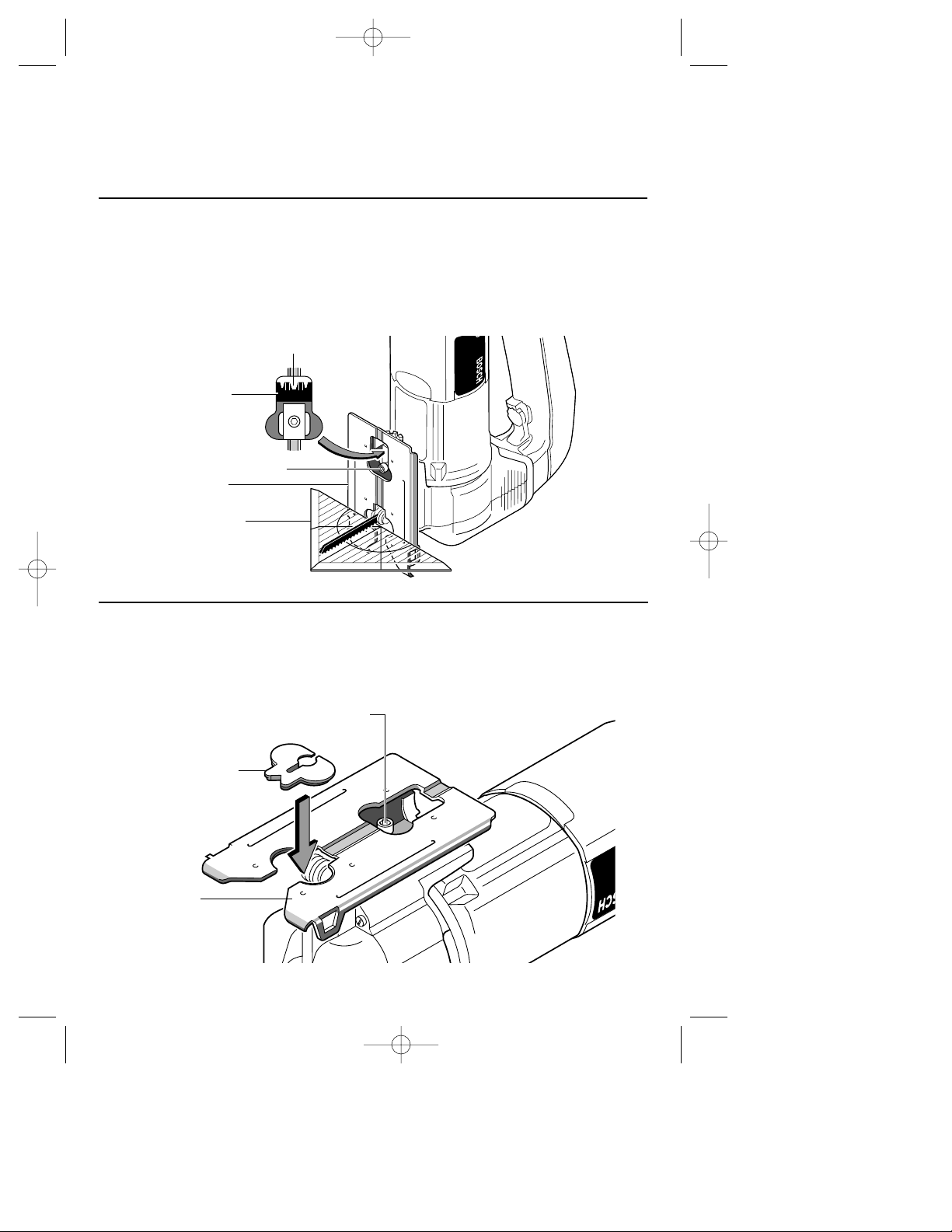
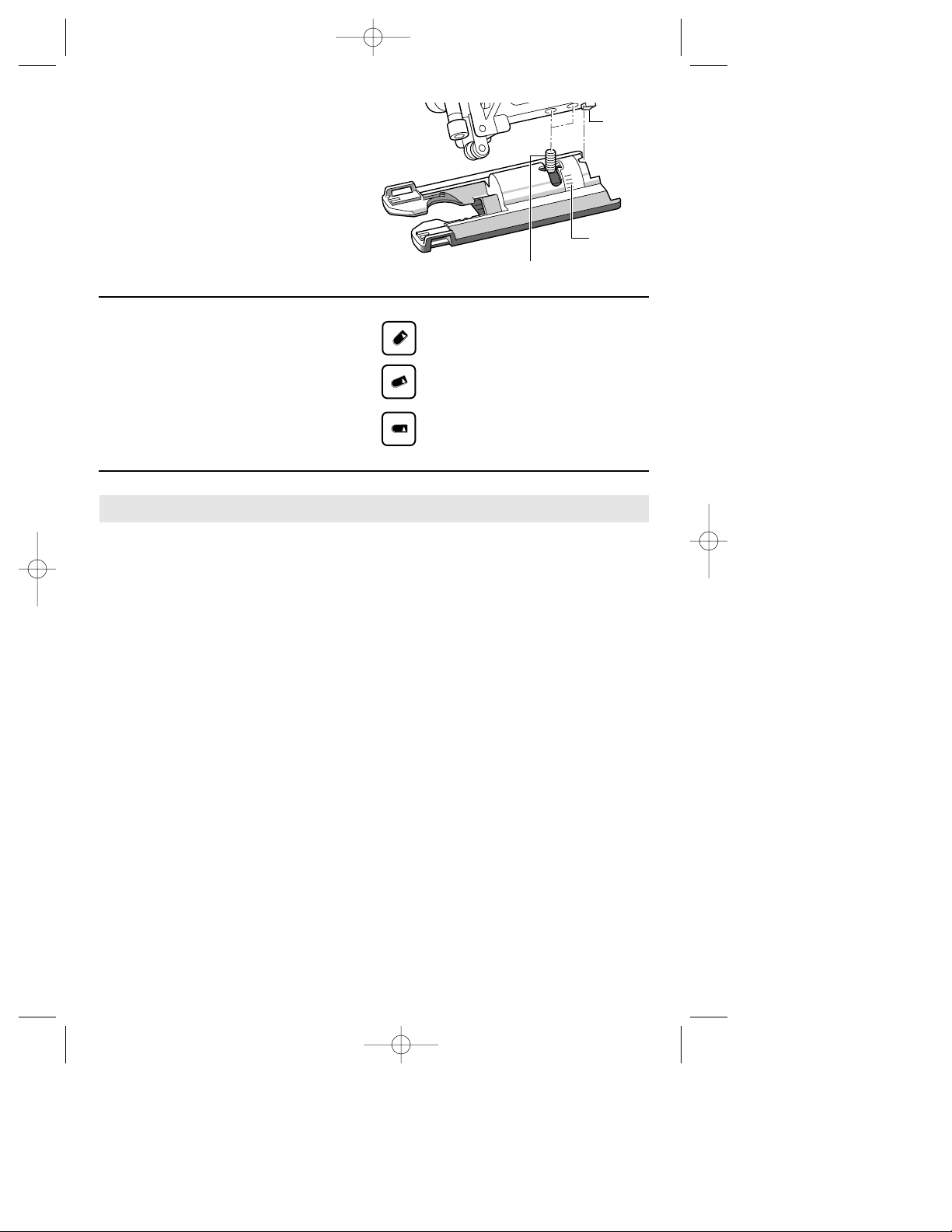
FOOTPLATE ANGLE ADJUSTMENT
The footplate may be tilted to allow angle cuts
up to 45˚ in either direction. To adjust
footplate, loosen screw with allen wrench, slide
the footplate towards the front of the tool, and
rotate to the desired angle, as marked on the
angle scale. Detent slots will hold the footplate
firmly at 45˚, and there are additional position
marks for 15˚ and 30˚ angles. Intermediate
angles may be set with a protractor. After
positioning the footplate, securely tighten
screw).
ANTI-SPLINTER INSERT
To minimize splintering of the top surface of
the material being cut, place the anti-splinter
insert in the blade opening of the footplate.
Note: This insert will only work with blades
that have ground sides such as T301CD,
T101B, T101D, and T101DP.
45
ANTI-SPLINTER
INSERT
SCREW
FOOTPLATE
0
15
30
45
15
30
45
DETENT SLOTS
ANGLE
SCALE
SCREW
FOOTPLATE
PROTRACTOR
(Not included)
The following types of blades should only be
used with orbital Setting O:
1. Blades with teeth that point downward
(reverse-tooth blades).
2. Blades with teeth that point straight out
rather than up or down.
3. Carbide-tipped blades.
4. Grit-edge blades.
BM 2610991830 1/02 1/21/02 12:20 PM Page 8
-9-
CHIP BLOWER
The jigsaw is equipped with a three-position
chip blower to help keep the cutting line clear
of chips. By adjusting the chip blower lever,
the force of the discharged air may be altered
as follows;
Strongest blowing action for working in
woods and similar materials.
Medium blowing action.
No blowing action
FLUSH CUTTING
To allow the saw to make a perpendicular cut
close to a vertical surface, the footplate may
be repositioned as follows. Remove screw,
move footplate to the front mounting slot, and
be sure the detent notch is aligned with the
detent slot in the footplate. Re-insert screw
into the threaded hole closest to the detent
notch, and securely tighten. Note that when
the footplate is retracted in this manner, only
90˚cuts are possible, and optional cutting
guide may not be used.
45
30
15
0
SCREW
ANGLE
SCALE
DETENT
NOTCH
Always be certain that smaller workpieces are
securely fastened to a bench or other support.
Larger panels may be held in place by clamps
on a bench or sawhorses.
To begin a cut, clearly mark the cutting line,
and rest the front of the footplate on the work.
Engage the switch, and move the blade into
the work using only enough forward pressure
to keep the blade cutting steadily. DO NOT
FORCE, as this will not make the saw cut
faster; let the blade do the work.
When cutting metal, it is often advisable to use
a lubricant to cool the blade and extend its life.
Choose blades carefully, as the ability of the
jigsaw to follow curves, provides smoother
finishes, or faster cutting is directly related to
the type of blade used.
BLADE SELECTION
• Choose blades carefully, as the ability of the
jigsaw to make the fastest cuts, to follow tight
curves, to achieve the smoothest finish and/or
to maximize the life of the blade are directly
related to the type of blade used.
• Always use a blade that is appropriate for the
cutting task.
• Always make a test cut in a piece of scrap
material.
• Most jigsaw blades have upward-pointing
teeth, which helps to pull the jigsaw against the
workpiece and minimizes vibration. Blades
with upward-pointing teeth produce a clean
cut on the bottom of the workpiece.
• Blades with downward-pointing teeth
(reverse-tooth blade) can be used to produce a
clean cut on the top of the workpiece (that side
that faces the jigsaw's footplate), such as
when cutting an already-installed countertop
from the top. When using reverse-tooth
blades, downward force must be applied to
the jigsaw.
• Blades with teeth that point straight out
(rather than up or down) allow splinter-free
cutting on both sides of the workpiece. When
using such blades, downward force must be
applied to the jigsaw.
• The following types of blades should only be
used with orbital Setting O:
1. Blades with teeth that point downward
(reverse-tooth blades).
2. Blades with teeth that point straight out
rather than up or down.
3. Carbide-tipped blades.
4. Grit-edge blades.
Tool Tips
BM 2610991830 1/02 1/21/02 12:20 PM Page 9
-10-
Service
Preventive maintenance
performed by unauthorized
personnel may result in misplacing of
internal wires and components which
could cause serious hazard. We
recommend that all tool service be
performed by a Bosch Factory Service
Center or Authorized Bosch Service Station.
TOOL LUBRICATION
Your Bosch tool has been properly
lubricated and is ready to use. It is
recommended that tools with gears be
regreased with a special gear lubricant at
every brush change.
CARBON BRUSHES
The brushes and commutator in your tool
have been engineered for many hours of
dependable service. To maintain peak
efficiency of the motor, we recommend
every two to six months the brushes be
examined. Only genuine Bosch replacement
brushes specially designed for your tool
should be used.
BEARINGS
After about 300-400 hours of operation, or at
every second brush change, the bearings
should be replaced at Bosch Factory Service
Center or Authorized Bosch Service Station.
Bearings which become noisy (due to heavy
load or very abrasive material cutting) should
be replaced at once to avoid overheating or
motor failure.
Cleaning
To avoid accidents always
disconnect the tool from
the power supply before cleaning or
performing any maintenance. The tool may
be cleaned most effectively with
compressed dry air. Always wear safety
goggles when cleaning tools with
compressed air.
Ventilation openings and switch levers must
be kept clean and free of foreign matter. Do
not attempt to clean by inserting pointed
objects through openings.
Certain cleaning agents
and solvents damage
plastic parts. Some of these are: gasoline,
carbon tetrachloride, chlorinated cleaning
solvents, ammonia and household
detergents that contain ammonia.
!
WARNING
!
WARNING
Maintenance
Accessories
!
CAUTION
If an extension cord is
necessary, a cord with
adequate size conductors that is capable
of carrying the current necessary for your
tool must be used. This will prevent
excessive voltage drop, loss of power or
overheating. Grounded tools must use 3wire extension cords that have 3-prong
plugs and receptacles.
NOTE: The smaller the gauge number, the
heavier the cord.
RECOMMENDED SIZES OF EXTENSION CORDS
120 VOLT ALTERNATING CURRENT TOOLS
!
WARNING
Tool’s
Ampere
Rating
Cord Size in A.W.G.
Wire Sizes in mm
2
3-6
6-8
8-10
10-12
12-16
18 16 16 14 .75 .75 1.5 2.5
18 16 14 12 .75 1.0 2.5 4.0
18 16 14 12 .75 1.0 2.5 4.0
16 16 14 12 1.0 2.5 4.0 —
14 12 — — — — — —
25 50 100 150 15 30 60 120
Cord Length in Feet Cord Length in Meters
* Screwdriver
* Blade locking screw
* Allen wrench 5mm
** Anti-splinter insert (5 pcs.)
** Cutting guide
* Carrying case (1581AVSK)
(*= standard equipment)
(**= optional accessories)
BM 2610991830 1/02 1/21/02 12:20 PM Page 10

-11-
Vous devez lire et comprendre toutes les instructions. Lenon-respect, même
partiel, des instructions ci-après entraîne un risque de choc életrique, d'incendie
et/ou de blessures graves.
CONSERVEZ CES INSTRUCTIONS
Règles de Sécurité Générales
AVERTISSEMENT
!
Aire de travail
Veillez à ce que l'aire de travail soit propre et bien
éclairée. Le désordre et le manque de lumière
favorisent les accidents.
N'utilisez pas d'outils électriques dans une
atmosphère explosive, par exemple enprésence de
liquides, de gaz ou de poussières inflammables. Les
outils électriques créent des étincelles qui pourraient
enflammer les poussières ou les vapeurs.
Tenez à distance les curieux, les enfants et les
visiteurs pendant que vous travaillezavec un outil
électrique. Ils pourraient vous distraire et vous faire
faire une fausse manoeuvre.
Sécurité électrique
Les outils à double isolation sont équipés d'une fiche
polarisée (une des lames est pluslarge que l'autre),
qui ne peut se brancher que d'une seule façon dans
une prise polarisée. Si la fiche n'entre pas
parfaitement dans la prise, inversez sa position ; si
elle n'entre toujours pasbien, demandez à un
électricien qualifié d'installer une prise de courant
polarisée. Ne modifiez pas la fiche de l'outil. La
double isolation élimine le besoin d'un cordon
d'alimentationà trois fils avec mise à la terre ainsi que
d'une prise de courant mise à la terre. Avant de
brancher l'outil, assurez-vous que la tension de la prise
correspond, à celle indiquée sur la plaque signalétique.
N'utilisez pas d'outils prévus pour courant alternatif
seulement avec une source de courant continu.
Évitez tout contact corporel avec des surfaces mises à
la terre (tuyauterie, radiateurs, cuisinières,
réfrigérateurs, etc.). Le risque de choc électrique est
plus grand si votre corps est encontact avec la terre. Si
l'utilisation de l'outil électrique dans un endroit humide
est inévitable, un disjoncteur de fuite à la terre doit être
utilisé pour alimenter votre outil. Des chaussures et des
gants en caoutchouc d'électricien contribueront à
accroître davantage votre sécurité personnelle.
N'exposez pas les outils électriques à la pluie ou à
l'eau. La présence d'eau dans un outil électrique
augmente le risque de choc électrique.
Ne maltraitez pas le cordon. Ne transportez pas l'outil
par son cordon et ne débranchez pas la fiche en tirant
sur le cordon. N'exposez pas le cordon à la chaleur, à
des huiles, à des arêtes vives ou à des pièces en
mouvement. Remplacez immédiatement un cordon
endommagé. Un cordon endommagé augmente le
risque de choc électrique.
Lorsque vous utilisez un outil électrique à l'extérieur,
employez un prolongateur pour l'extérieur marqué «
W-A » ou « W ». Ces cordons sont faits pour être
utilisés à l'extérieur et réduisent le risque de choc
électrique. Reportez-vous aux « Dimensions
recommandées des cordons de rallonge » dans la
section Accessoires de ce manuel.
Sécurité des personnes
Restez alerte, concentrez-vous sur votre travail et
faites preuve de jugement. N'utilisez pas un outil
électrique si vous êtes fatigué ou sous l'influence de
drogues, d'alcool ou de médicaments. Un instant
d'inattention suffit pour entraîner des blessures graves.
Habillez-vous convenablement. Ne portez ni
vêtements flottants ni bijoux. Confinez les cheveux
longs. N'approchez jamais les cheveux, les
vêtements ou les gants des pièces en mouvement.
Des vêtements flottants, des bijoux ou des cheveux
longs risquent d'être happés par des pièces en
mouvement. Gardez les poignées sèches, propres et
exemptes d'huile et de graisse.
Méfiez-vous d'un démarrage accidentel. Avant de
brancher l'outil, assurez-vous que son interrupteur est
sur ARRÈT. Le fait de transporter un outil avec le doigt
sur la détente ou de brancher un outil dont l'interrupteur
est en position MARCHE peut mener tout droit à un
accident.
Enlevez les clés de réglage ou de serrage avant de
démarrer l'outil. Une clé laissée dans une pièce
tournante de l'outil peut provoquer des blessures.
Ne vous penchez pas trop en avant. Maintenez un bon
appui et restez en équilibre entout temps. Un bonne
stabilité vous permet de mieux réagir à une situation
inattendue.
Utilisez des accessoires de sécurité. Portez toujours
des lunettes ou une visière. Selon les conditions,
portez aussi un masque antipoussière, des bottes de
sécurité antidérapantes, un casque protecteur et/ou un
appareil antibruit.
Utilisation et entretien des outils
Immobilisez le matériau sur une surface stable au
moyen de brides ou de toute autre façon adéquate. Le
fait de tenir la pièce avec la main ou contre votre corps
offre une stabilité insuffisante et peut amener un
dérapage de l'outil.
Ne forcez pas l'outil. Utilisez l'outil approprié à la
tâche. L'outil correct fonctionne mieux et de façon plus
BM 2610991830 1/02 1/21/02 12:20 PM Page 11

-12-
Tenez l'outil par les surfaces isolées de préhension
en exécutant une opération au cours de laquelle
l'outil de coupe peut venir en contact avec les fils
cachés ou son propre cordon. Le contact avec un fil
sous tension rendra les pièces métalliques exposées
de l'outil sous tension et causera des chocs à
l'opérateur. Ne percez, fixez et ne rentrez pas dans
des murs existants ou autres endroits aveugles
pouvant abriter des fils électriques. Si cette situation
est inévitable, débranchez tous les fusibles ou les
disjoncteurs alimentant ce site.
Ne tenez jamais la gâchette bloquée en position de
marche. Avant de brancher l'outil, assurez-vous
que le blocage de la gâchette est inhibé. Les mises
en marche accidentelles peuvent causer des
blessures.
Soyez au courant de l'emplacement et de la
position du bouton de blocage en marche de la
gâchette. Si l'interrupteur est bloqué en marche
durant l'usage, soyez prêt, dans des cas d'urgence, à
le mettre à l'arrêt en appuyant d'abord sur la
gâchette, puis en la relâchant immédiatement sans
appuyer sur le bouton de blocage en marche.
Gardez les mains à l'écart de la zone de coupe. Ne
placez surtout pas la main sous le matériau que
vous coupez. Il est impossible de déterminer
exactement la proximité de la lame de votre main.
Évitez de vous placer les mains entre le carter
d'engrenages et le porte-lame de la scie. Le porte-
lame à mouvement alternatif risquerait de vous pincer
les doigts.
N'utilisez pas de lames émoussées ou
endommagées. Les lames pliées peuvent aisément
se fracturer ou causer un rebond.
Avant de commencer à couper, mettez l'outil en
marche et attendez que la lame atteigne sa vitesse
maximale. L'outil peut trembler ou vibrer si la vitesse
de la lame est trop lente au début de la coupe, et il
peut éventuellement rebondir.
Portez toujours des lunettes à coques latérales ou
des lunettes de protection en utilisant cet outil.
Utilisez un respirateur ou un masque antipoussières pour les applications produisant de la
poussière.
Il importe de bien assujettir la pièce sur laquelle
vous travaillez. Ne la tenez jamais dans votre main
ou sur vos jambes. Les pièces minces et plus petites
peuvent fléchir ou vibrer avec la lame, risquant ainsi
de vous faire perdre le contrôle.
sécuritaire. Respectez aussi la vitesse de travail qui lui
est propre.
N'utilisez pas un outil si son interrupteur est bloqué.
Un outil que vous ne pouvez pas commander par son
interrupteur est dangereux et doit être réparé.
Débranchez la fiche de l'outil avant d'effectuer un
réglage, de changer d'accessoire oude ranger l'outil.
De telles mesures préventives de sécurité réduisent le
risque de démarrage accidentel de l'outil.
Rangez les outils hors de la portée des enfants et
d'autres personnes inexpérimentées. Les outils sont
dangereux dans les mains d'utilisateurs novices.
Prenez soin de bien entretenir les outils. Les outils de
coupe doivent être toujours bien affûtés et propres.
Des outils bien entretenus, dont les arêtes sont bien
tranchantes, sont moins susceptibles de coincer et plus
faciles à diriger.Toute altération ou modification
constitue un usage erroné et peut causer un danger.
Soyez attentif à tout désalignement ou coincement
des pièces en mouvement, à tout bris ou à toute autre
condition préjudiciable au bon fonctionnement de
l'outil. Si vous constatez qu'un outil est endommagé,
faites-le réparer avant de vous en servir. De
nombreux accidents sont causés par des outils en
mauvais état. Élaborez un calendrier d'entretien
périodique de votre outil.
N'utilisez que des accessoires que le fabricant
recommande pour votre modèle d'outil. Certains
accessoires peuvent convenir à un outil, mais être
dangereux avec un autre.
Réparation
La réparation des outils électriques doit être confiée
à un réparateur qualifié. L'entretien ou la réparation
d'un outil électrique par un amateur peut avoir des
conséquences graves. Ainsi, des fils internes peuvent
être mal placés ou pincés, des ressorts de rappel de
protecteur peuvent être montés erronément.
Pour la réparation d'un outil, n'employez que des
pièces de rechange d'origine. Suivez les directives
données à la section « Réparation » de ce manuel.
L'emploi de pièces non autorisées ou le non-respect
des instructions d'entretien peut créer un risque de
choc électrique ou de blessures. Certains agents
nettoyants tels qu'essence, tétrachlorure de carbone,
ammoniac, etc., peuvent abîmer les pièces en plastique.
Règles de sécurité concernant les scies sauteuses
BM 2610991830 1/02 1/21/02 12:20 PM Page 12

-13-
Avant de commencer à scier, assurez-vous que
toutes les vis de réglage et que le porte-lame sont
serrés. Les vis de réglage et porte-lame lâches
peuvent faire glisser l'outil ou la lame et ainsi vous
faire perdre le contrôle.
En retirant la lame de l'outil, évitez le contact avec
la peau et utilisez des gants protecteurs appropriés
en saisissant la lame ou l'accessoire. Les
accessoires peuvent être chauds après un usage
prolongé.
Si votre outil est muni d’un sac à poussière, videz-le
fréquemment et après chaque opération de sciage.
Une autocombustion peut se déclencher en réaction au
mélange de l’huile ou de l’eau et des particules de
poussière. La mise au rebut des poussières doit être
extrêmement bien supervisée, les matériaux sous forme
de particules fines pouvant être explosifs. Ne pas mettre
le contenu en contact direct avec le feu.
Les travaux à la machine
tel que ponçage, sciage,
meulage, perçage et autres travaux du bâtiment
peuvent créer des poussières contenant des produits
chimiques qui sont des causes reconnues de cancer,
de malformation congénitale ou d’autres problèmes
reproductifs. Ces produits chimiques sont, par
exemple :
• Le plomb provenant des peintures à base de plomb,
• Les cristaux de silices provenant des briques et du
ciment et d’autres produits de maçonnerie, et
• L’arsenic et le chrome provenant des bois traités
chimiquement
Le niveau de risque dû à cette exposition varie avec la
fréquence de ces types de travaux. Pour réduire
l’exposition à ces produits chimiques, il faut travailler
dans un lieu bien ventilé et porter un équipement de
sécurité approprié tel que certains masques à poussière
conçus spécialement pour filtrer les particules
microscopiques.
AVERTISSEMENT
!
BM 2610991830 1/02 1/21/02 12:20 PM Page 13
-14-
Symboles
Important : Certains des symboles suivants peuvent être utilisés sur votre outil. Veuillez les étudier et apprendre
leur signification. Une interprétation appropriée de ces symboles vous permettra d'utiliser l'outil de façon plus
efficace et plus sûre.
Symbole Nom Désignation/Explication
V Volts Tension (potentielle)
A Ampères Courant
Hz Hertz Fréquence (cycles par seconde)
W Watt Puissance
kg Kilogrammes Poids
min Minutes Temps
s Secondes Temps
Diamètre Taille des mèches de perceuse, meules,
etc.
n
0
Vitesse à vide Vitesse de rotation, à vide
.../min Tours ou mouvement alternatif par Tours, coups, vitesse en surface, orbites,
minute etc., par minute,
0 Position d'arrêt Vitesse zéro, couple zéro ...
1, 2, 3, ... Réglages du sélecteur Réglages de vitesse, de couple ou de
l, ll, lll, ... position. Un nombre plus élevé signifie
une vitesse plus grande.
Sélecteur variable à l'infini avec arrêt La vitesse augmente depuis le réglage 0
Flèche Action dans la direction de la flèche
Courant alternatif Type ou caractéristique du courant
Courant continu Type ou caractéristique du courant
Courant alternatif Type ou caractéristique du courant
ou continu
Construction classe II Désigne des outils construits avec double
isolation
Borne de terre borne de mise à la terre
Symbole d'avertissement Alerte l'utilisateur aux messages
d'avertissement.
Sceau Ni-Cad RBRCmc Désigne le programme de recyclage des piles
Ni-Cad.
0
Ce symbole signifie que cet
outil est approuvé par
Underwriters Laboratories.
Ce symbole signifie que cet
outil est approuvé par
l'Association canadienne de
normalisation.
Ce symbole signifie que
cet outil est approuvé
conformément aux normes
canadiennes par Underwriters
Laboratories.
Ce symbole
signifie que
cet outil se
conforme aux
normes
mexicaines
NOM.
Ce symbole signifie que cet outil
est approuvé par Underwriters
Laboratories et qu’il a été
homologué selon les normes
canadiennes par Underwriters
Laboratories.
BM 2610991830 1/02 1/21/02 12:20 PM Page 14

-15-
Description fonctionnelle et spécifications
Débranchez la fiche de la prise de courant avant d'effectuer quelque assemblage
ou réglage que ce soit ou de changer les accessoires. Ces mesures de sécurité
préventive réduisent le risque d'une mise en marche accidentelle de l'outil.
AVERTISSEMENT
!
Scies sauteuses
Capacités maximales :
Matériau Dimensions
Bois 60 mm (2 3/8 po)
Plastique 32 mm (1 1/4 po)
Aluminium 20 mm (3/4 po)
Métal non ferreux 20 mm (3/4 po)
Acier doux 10 mm (3/8 po)
Acier inoxydable 3 mm (1/8 po)
Acier allié 3 mm (1/8 po)
TROU
SUPÉRIEUR DE
PLONGEUR
BOUTON DE BLOCAGE EN MARCHE
CADRAN DE RÉGLAGE DE
VITESSE DE GÂCHETTE
GÂCHETTE DE COMMANDE
CLÉ ALLEN
5 MM
PRISES D’AIR
LEVIER SOUFFLE-COPEAUX
GUIDE À ROULEAUX DE LAME
LEVIER SÉLECTEUR D’ORBITE DE LAME
FENTES DE MONTAGE DU GUIDE DE COUPE
LAME
PLONGEUR
DE LAME
SEMELLE
PRISES D’AIR
BM 2610991830 1/02 1/21/02 12:20 PM Page 15

-16-
Assemblage
GÂCHETTE DE COMMANDE À VITESSE VARIABLE
Votre outil est équipé d’une gâchette de commande à
vitesse variable. Vous pouvez mettre le outil en marche
ou au repos en appuyant ou en relâchant la gâchette
respectivement. Dépendant de la pression exercée sur la
gâchette, il est possible de régler la vitesse dans les
limites minimale et maximale spécifiées sur la plaquette
emblématique. Exercez plus de pression pour
augmenter la vitesse et moins pour la diminuer.
BOUTON DE BLOCAGE EN MARCHE
La outil est également pourvue d’un bouton de blocage
en marche situé du côté gauche de la poignée de la
gâchette qui permet le fonctionnement au régime
maximum — sans devoir tenir la gâchette.
POUR BLOQUER L’INTERRUPTEUR EN MARCHE :
appuyez sur la gâchette, appuyez sur le bouton et
relâchez la gâchette.
POUR DEBLOQUER L’INTERRUPTEUR : appuyez sur la
gâchette et relâchez-la sans appuyer sur le bouton de
blocage en marche.
Si l’utilisateur appuie
continuellement sur le
bouton de blocage en marche, la gâchette ne peut pas
être relâchée.
CADRAN DE RÉGLAGE DE VITESSE DE GÂCHETTE
Cette fonction vous permet d’établir les vitesses
désirées en tournant le cadran de la gâchette vers un
réglage plus haut ou plus bas. Quelle que soit la
pression que vous exerciez sur la gâchette, l’outil ne
fonctionnera pas plus vite que las vitesse maximale
choisie.
Réglage
A-B Bas taux de courses
C-D Taux moyen de courses
E Taux élevé de courses
VITESSE DU PLONGEUR
Le taux de course ou vitesse de coupe nécessaire sur
la scie à découper dépend du matériau coupé, du type
de lame employé, et du taux d’alimentation que préfère
l’opérateur. La vitesse convenant le mieux à une
application particulière est essentiellement dictée par
l’expérience bien qu’en règle générale, les vitesses plus
basses soient destinées aux matériaux plus denses et
les vitesses plus rapides aux matériaux mous. Il
convient de remarquer que, lorsque à scie à découper
est utilisée à bas régime pendant un certain temps, la
température du moteur augmente en raison de la
vitesse réduite du ventilateur interne. Il faut alors faire
fonctionner l’outil à l’occasion à régime maximal
pendant quelques minutes pour ne pas compromettre
l’efficacité du moteur.
ORBITE DE LA LAME
Une efficacité de coupe maximale peut être obtenue en
ajustant le levier sélecteur d’orbite de lame en fonction
du matériau coupé. Le tableau suivant vous aidera à
établir le réglage à utiliser pour votre application. Ce
tableau ne constitue qu’un guide, et il faut d’abord
procéder à des coupes d’essai dans un matériau de
rebut pour déterminer le meilleur réglage.
Réglage O matériaux durs tels que métaux ou tôles
minces ; s’emploie avec lames de
couteau, lames à bord abrasif ou travail
de râpe
Réglage I matériaux mous où une coupe plus nette
ou un travail délicat de découpape est
pratiqué
Réglage II matériaux à densité moyenne tels que
bois plus durs ou panneau de particules
Réglage III matériaux mous tels que bois, plastiques,
etc.
POSE DE LA LAME
Placez le levier sélecteur d’orbite de lame à la position
III.
Insérez le tournevis fourni dans le trou supérieur de
plongeur et desserrez la vis de fixation de lame interne
d’environ 3 à 4 tours en sens anti-horaire.
Insérez la lame dans le plongeur de lame à un angle de
90° par rapport à la direction de coupe. En exerçant
une légère pression vers le haut, tournez les dents de
la lame vers l’avant (direction de la coupe) et guidez
l’arrière de la lame dans la rainure au centre du guide à
rouleaux de lame. Tirez délicatement la lame vers le
bas de manière à caler les languettes dans le plongeur.
La lame étant à la bonne position, serrez la vis de la
lame à bloc en tournant le tournevis en sens horaire.
Pour déposer la lame, il suffit essentiellement
d’inverser la procédure de pose ; cependant, il convient
de noter qu’une fois la vis de la lame desserrée, il faut
pousser délicatement la lame vers le haut pour relâcher
les languettes de la lame du plongeur.
Consignes de fonctionnement
AVERTISSEMENT
!
BM 2610991830 1/02 1/21/02 12:20 PM Page 16

-17-
RÉGLAGE DE L’ANGLE DE LA SEMELLE
La semelle peut être inclinée de manière à permettre
des coupes à angle allant jusqu’à 45° dans l’une ou
l’autre direction. Pour ajuster la semelle, desserrez la
vis à l’aide de la clé Allen, faites glisser la semelle vers
l’avant de l’outil, et tournez à l’angle désiré, comme
marqué sur l’échelle d’angle. Les fentes d’arrêt
tiendront la semelle fermement à un angle de 45°, et il
y a d’autres marques de posi-tion pour les angles de et
de 30 degrés. Des angles intermédiaires peuvent être
définis à l’aide du compas. Après avoir positionné la
semelle, serrez la vis à bloc.
DISPOSITIF ANTI-ÉCLATS
Pour réduire les éclats au minimum sur la surface
supérieure du matériau coupé, insérez le dispositif
anti-éclats dans l’ouverture de lame sur la semelle.
Remarque : ce dispositif ne peut être utilisé qu’avec les
lames présentant des côtés meulés telles que T301CD,
T101B, T101D et T101DP.
0
15
30
45
15
30
45
FENTES D’ARRÊT
ÉCHELLE D’ANGLE
VIS
SEMELLE
COMPAS (NON OFFERT
PAR BOSCH)
45
DISPOSITIF ANTI-
ÉCLATS
VIS
SEMELLE
Les types de lame suivants ne peuvent être utilisés
qu’avec l’orbite réglée à O :
1. Lames à dents inclinées vers le bas (lames à dents
inversées);
2. Lames à dents droites au lieu d’être inclinées vers le
haut ou le bas;
3. Lames à dents carbures (ou à dents traitées);
4. Lames à bord granuleux.
BM 2610991830 1/02 1/21/02 12:20 PM Page 17

-18-
Assurez-vous toujours que les petites pièces de travail
sont fixées solidement à un établi ou autre support. Les
grands panneaux peuvent être tenus en place à l’aide
de serres sur un établi ou un chevalet de scieur.
Pour commencer une coupe, marquez clairement la
ligne de coupe et reposez l’avant de la semelle sur le
matériau. Mettez l’interrupteur en position de marche,
et déplacez la lame dans le matériau en utilisant tout
juste assez de pression avant pour maintenir une
coupe régulière. NE FORCEZ PAS : la scie ne coupera
pas plus rapidement pour autant ; laissez la lame faire
le travail.
Lors de la coupe de métaux, il est souvent préférable
d’utiliser un lubrifiant pour refroidir la lame et en
prolonger la durée.
Choisissez les lames soigneusement, car la capacité de
la scie de suivre les courbes, d’assurer des finis plus
lisses ou de couper plus rapidement est directement
liée au type de lame employé.
CHOIX DE LA LAME
• Choissiez les lames avec soin : l’aptitude de la scie
sauteuse à scier rapidement, à suivre des fortes
courbes, à obtenir des finis réguliers ou à maximiser la
durée de vie de la lame dépend directement du type de
lame utilisé.
• Utilisez toujours une lame adaptée à la tâche à
effectuer.
• Faites toujours une coupe d’essai sur une chute.
• La plupart des lames de scie sauteuse ont les dents
inclinées vers le haut, ce qui tend à plaquer la scie
sauteuse contre la pièce et à minimiser les vibrations.
Les lames avec des dents inclinées vers le haut
produisent une coupe propre sur le dessous de la
pièce.
• Les lames à dents inclinées vers le bas (lames à dents
inversées) peuvent être utilisées pour produire une
coupe propre sur le dessus de la pièce (la face qui est
en contact avec la semelle de la scie sauteuse), comme
par exemple pour scier sur le dessus d’un plan de
travail déjà installé. Lorsqu’on utilise des lames à
dents inversées, il faut exercer une pression vers le bas
sur la scie sauteuse.
• Les lames à dents droites (au lieu d’être inclinées vers
le haut ou le bas) permettent de scier sans éclater sur
les deux faces de la pièce. Lorsqu’on utilise de telles
lames, il faut exercer une pression vers le bas sur la
scie sauteuse.
• Les types de lame suivants ne peuvent être utilisés
qu’avec l’orbite réglée à O :
1. Lames à dents inclinées vers le bas (lames à dents
inversées);
2. Lames à dents droites au lieu d’être inclinées vers le
haut ou le bas;
3. Lames à dents carbures (ou à dents traitées);
4. Lames à bord granuleux.
Conseils pratiques
COUPE À RAS
Pour permettre à la scie de pratiquer une coupe
perpendiculaire à proximité d’une surface verticale, la
semelle peut être repositionnée de la manière suivante.
Retirez la vis, déplacez la semelle à la fente de montage
avant, et assurez-vous que le cran d’arrêt est aligné sur
la fente d’arrêt de la semelle. Réinsérez la vis dans le
trou fileté le plus rapproché du cran d’arrêt et serrez à
bloc. Il convient de noter que, lorsque la semelle est
rétractée de cette manière, seules des coupes de 90°
peuvent être pratiquées et le guide de coupe facultatif
ne peut pas être utilisé.
SOUFFLE-COPEAUX
La scie à découper est pourvue d’un souffle-copeaux à
trois positions pour mieux garder la ligne de coupe
exempte de copeaux. En réglant le levier du soufflecopeaux, on peut modifier la force de l’air évacué de la
manière suivante :
Soufflage le plus fort pour le travail du bois et
de matériaux similaires
Soufflage moyen
Aucun soufflage
45
30
15
0
VIS
ÉCHELLE
D’ANGLE
CRAN
D’ARRÊT
BM 2610991830 1/02 1/21/02 12:20 PM Page 18

-19-
Entretien
L’entretien préventif
effectué par des employés
non autorisés peut entraîner un positionnement
erroné des composants et des fils internes, et ainsi
causer des dangers sévères. Il est recommandé que
l’entretien et la réparation de nos outils soient confiés
à un centre de service-usine Bosch ou à un centre de
service après-vente Bosch agréé.
GRAISSAGE DE L’OUTIL
Votre outil Bosch a été convenablement graissé et est
prêt à utiliser. Il est recommandé que les outils à
engrenages soient regraissés avec une graisse
spéciale à l’occasion de tout remplacement de balais.
BALAIS DE CHARBON
Les balais et le collecteur de votre outil ont été
conçus pour donner plusieurs heures de
fonctionnement sans aléas. Pour maintenir le moteur
en forme, nous recommandons d’examiner les balais
tous les deux à six mois. Vous ne devriez utiliser que
les balais de rechange d’origine Bosch qui conviennent spécialement à votre outil.
ROULEMENTS
Après environ 300 à 400 heures d’utilisation, ou à
tous les deux remplacements des balais, il faudrait
confier le remplacement des roulements à un centre
de service-usine Bosch ou à un centre de service
après-vente Bosch agréé. Les roulements qui sont
devenus bruyants (à cause de sciage de matériaux
très abrasifs ou de durs efforts) devraient être
remplacés à l’instant pour éviter la surchauffe et la
défaillance du moteur.
Nettoyage
Pour éviter le risque
d’accidents, débranchez
toujours l’outil de la prise de courant avant de
procéder au nettoyage ou à l’entretien. Vous pouvez
très bien le nettoyer à l’air comprimé. Dans ce cas,
portez toujours des lunettes de sécurité.
Gardez les prises d’air et les interrupteurs propres et
libres de débris. N’essayez pas de les nettoyer en
introduisant des objets pointus dans leurs ouvertures.
Certains produits de
nettoyage et dissolvants
dont la gazoline, le tétrachlorure de carbone, les
nettoyeurs chlorés, l’ammoniaque et les détergents
ménagers contenant de l’ammoniaque peuvent
abîmer les pièces en plastique.
Maintenance
AVERTISSEMENT
!
AVERTISSEMENT
!
Accessoires
Si un cordon de rallonge
s'avère nécessaire, vous
devez utiliser un cordon avec conducteurs de
dimension adéquate pouvant porter le courant
nécessaire à votre outil. Ceci préviendra une chute
excessive de tension, une perte de courant ou une
surchauffe. Les outils mis à la terre doivent utiliser des
cordons de rallonge trifilaires pourvus de fiches à trois
broches ainsi que des prises à trois broches.
REMARQUE : Plus le calibre est petit, plus le fil est gros.
DIMENSIONS DE RALLONGES RECOMMANDÉES
OUTILS 120 VOLTS COURANT ALTERNATIF
AVERTISSEMENT
!
Intensité
nominale
de l’outil
Longueur en pieds
Longueur en mètres
3-6
6-8
8-10
10-12
12-16
18 16 16 14 .75 .75 1.5 2.5
18 16 14 12 .75 1.0 2.5 4.0
18 16 14 12 .75 1.0 2.5 4.0
16 16 14 12 1.0 2.5 4.0 —
14 12 — — — — — —
25 50 100 150 15 30 60 120
Calibre A.W.G.
Calibre en mm
2
* Tournevis
* Vis de blocage de lame
* Clé Allen 5 mm
**Dispositif anti-éclats (5 pièces)
**Guide de coupe
* Étui (1581AVSK)
(*= équipment standard)
(**= accessorie en option)
MISE EN GARDE
!
BM 2610991830 1/02 1/21/02 12:20 PM Page 19

-20-
Lea y entienda todas las instrucciones. El incumplimiento de todas las instrucciones
indicadas a continuación puede dar lugar a sacudidas eléctricas, incendios y/o lesiones
personales graves.
CONSERVE ESTAS INSTRUCCIONES
Normas de seguridad para herramientas mecánicas
ADVERTENCIA
!
Area de trabajo
Mantenga el área de trabajo limpia y bien iluminada.
Las mesas desordenadas y las áreas oscuras invitan a
que se produzcan accidentes.
No utilice herramientas mecánicas en atmósferas
explosivas, tales como las existentes en presencia de
líquidos, gases o polvos inflamables. Las
herramientas mecánicas generan chispas y éstas
pueden dar lugar a la ignición del polvo o los vapores.
Mantenga a las personas que se encuentren
presentes, a los niños y a los visitantes alejados al
utilizar una herramienta mecánica. Las distracciones
pueden hacer que usted pierda el control.
Seguridad eléctrica
Las herramientas con aislamiento doble están
equipadas con un enchufe polarizado (un terminal es
más ancho que el otro). Este enchufe entrará en un
tomacorriente polarizado solamente de una manera.
Si el enchufe no entra por completo en el
tomacorriente, déle la vuelta. Si sigue sin entrar,
póngase en contacto con un electricista competente
para instalar un tomacorriente polarizado. No haga
ningún tipo de cambio en el enchufe. El aislamiento
doble elimina la necesidad del sistema de cordón de
energía de tres hilos conectado a tierra y la fuente de
energía conectada a tierra. Antes de enchufar la
herramienta, asegúrese de que la tensión del
tomacorriente suministrada se encuentre dentro del
margen de la tensión especificada en la placa del
fabricante. No utilice herramientas con capacidad
nominal "AC solamente" ("AC only") con una fuente de
energía DC.
Evite el contacto del cuerpo con las superficies
conectadas a tierra tales como tuberías, radiadores,
estufas de cocina y refrigeradores. Hay mayor riesgo
de que se produzcan sacudidas eléctricas si su cuerpo
está conectado a tierra. Si la utilización de la
herramienta mecánica en lugares húmedos es
inevitable, se debe usar un interruptor de circuito para
fallos a tierra para suministrar la energía a la
herramienta. Los guantes de goma para electricista y el
calzado antideslizante aumentarán más la seguridad
personal.
No exponga las herramientas mecánicas a la lluvia ni
a situaciones húmedas. La entrada de agua en una
herramienta mecánica aumentará el riesgo de que se
produzcan sacudidas eléctricas.
No abuse del cordón. Nunca use el cordón para llevar
las herramientas ni para sacar el enchufe de un
tomacorriente. Mantenga el cordón alejado del calor, el
aceite, los bordes afilados o las piezas móviles. Cambie
los cordones dañados inmediatamente. Los cordones
dañados aumentan el riesgo de que se produzcan
sacudidas eléctricas.
Al utilizar una herramienta mecánica a la intemperie,
utilice un cordón de extensión para intemperie
marcado "W-A" o "W". Estos cordones tienen
capacidad nominal para uso a la intemperie y reducen el
riesgo de que se produzcan sacudidas eléctricas.
Consulte "Tamaños recomendados de los cordones de
extensión" en la sección Accesorios de este manual.
Seguridad personal
Manténgase alerta, fíjese en lo que está haciendo y
use el sentido común cuando utilice una herramienta
mecánica. No use la herramienta cuando esté
cansado o se encuentre bajo la influencia de drogas,
alcohol o medicamentos. Un momento de distracción
al utilizar herramientas mecánicas puede dar lugar a
lesiones personales graves.
Vístase adecuadamente. No se ponga ropa holgada ni
joyas. Sujétese el pelo. Mantenga el pelo, la ropa y
los guantes alejados de las piezas móviles. La ropa
holgada, las joyas o el pelo largo pueden quedar
atrapados en las piezas móviles. Mantenga los mangos
secos, limpios y libres de aceite y grasa.
Evite el arranque accidental. Asegúrese de que el
interruptor esté en la posición "OFF" (apagado) antes
de enchufar la herramienta. El llevar las herramientas
con el dedo en el interruptor o el enchufar herramientas
que tengan el interruptor en la posición "ON"
(encendido) invita a que se produzcan accidentes.
Quite las llaves de ajuste o de tuerca antes de
encender la herramienta. Una llave de ajuste o de
tuerca que se deje puesta en una pieza giratoria de la
herramienta puede ocasionar lesiones personales.
No intente alcanzar demasiado lejos. Mantenga un
apoyo de los pies y un equilibrio adecuados en todo
momento. El apoyo de los pies y el equilibrio
adecuados permiten un mejor control de la herramienta
en situaciones inesperadas.
Utilice equipo de seguridad. Use siempre protección
de los ojos. Se debe utilizar una máscara antipolvo,
zapatos de seguridad antideslizantes, casco o
protección de los oídos según lo requieran las
condiciones.
Utilización y cuidado de las herramientas
Utilice abrazaderas u otro modo práctico de fijar y
soportar la pieza de trabajo a una plataforma estable.
BM 2610991830 1/02 1/21/02 12:20 PM Page 20

-21-
Normas de seguridad para sierras de vaivén
Sujete la herramienta por las superficies de agarre
aisladas cuando realice una operación en la que la
herramienta de corte pueda entrar en contacto con
cables ocultos o con su propio cordón. El contacto
con un cable que tenga corriente hará que ésta pase a
las partes metálicas descubiertas de la herramienta y
que el operador reciba sacudidas eléctricas. No
taladre, rompa, ni haga trabajo de sujeción en
paredes existentes ni en otras áreas ciegas donde
pueda haber cables eléctricos. Si esta situación es
inevitable, desconecte todos los fusibles o
cortacircuitos que alimentan este sitio de trabajo.
Nunca deje el gatillo fijo en la posición "ON"
(encendido). Antes de enchufar la herramienta,
compruebe que el cierre del gatillo esté en la
posición "OFF" (apagado). Un arranque accidental
podría causar lesiones.
Sepa la ubicación y la posición del botón de
"Fijación en ON" del interruptor. Si el interruptor
está fijo en la posición "ON" durante el uso, esté
preparado para en situaciones de emergencia ponerlo
en "OFF", tirando primero del gatillo y soltándolo
inmediatamente después sin oprimir el botón de
"Fijación en ON".
Mantenga las manos alejadas del área de corte.
No ponga la mano debajo del material que se está
cortando. La proximidad de la hoja a la mano queda
oculta a la vista.
Mantenga las manos alejadas del espacio entre la
caja de engranajes y el soporte de la hoja de
sierra. El soporte de la hoja de vaivén puede
pellizcarle los dedos.
No utilice hojas desfiladas ni dañadas. Una hoja
doblada puede romperse fácilmente o causar
retroceso.
Antes de comenzar el corte, encienda la
herramienta y deje que la hoja alcance toda su
velocidad. La herramienta puede chirriar o vibrar si
la velocidad de la hoja es demasiado lenta al
comienzo del corte y posiblemente puede
experimentar retroceso.
La sujeción de la pieza de trabajo con la mano o contra
el cuerpo resulta inestable y puede ocasionar pérdida de
control.
No fuerce la herramienta. Use la herramienta
correcta para la aplicación que desea. La herramienta
correcta hará el trabajo mejor y con más seguridad a la
capacidad nominal para la que está diseñada.
No utilice la herramienta si el interruptor no la
enciende o apaga. Toda herramienta que no se pueda
controlar con el interruptor es peligrosa y debe ser
reparada.
Desconecte el enchufe de la fuente de energía antes
de hacer cualquier ajuste, cambiar accesorios o
guardar la herramienta. Estas medidas de seguridad
preventivas reducen el riesgo de arrancar la herramienta
accidentalmente.
Guarde las herramientas que no esté usando fuera
del alcance de los niños y otras personas no
capacitadas. Las herramientas son peligrosas en las
manos de los usuarios no capacitados.
Mantenga las herramientas con cuidado. Conserve
las herramientas de corte afiladas y limpias. Las
herramientas mantenidas adecuadamente, con bordes
de corte afilados, tienen menos probabilidades de
atascarse y son más fáciles de controlar. Toda
alteración o modificación constituye un uso incorrecto y
puede tener como resultado una situación peligrosa.
Compruebe la desalineación o el atasco de las piezas
móviles, la ruptura de piezas y cualquier otra
situación que pueda afectar el funcionamiento de las
herramientas. Si la herramienta está dañada, haga
que realicen un servicio de ajustes y reparaciones a
la herramienta antes de usarla. Muchos accidentes
son causados por herramientas mantenidas
deficientemente. Establezca un programa de
mantenimiento periódico para la herramienta.
Utilice únicamente accesorios que estén
recomendados por el fabricante de su modelo. Los
accesorios que pueden ser adecuados para una
herramienta pueden volverse peligrosos cuando se
utilizan en otra herramienta.
Servicio
El servicio de ajustes y reparaciones de una
herramienta debe ser realizado únicamente por
personal de reparaciones competente. El servicio o
mantenimiento realizado por personal no competente
podría ocasionar un peligro de que se produzcan
lesiones. Por ejemplo: Los cables internos pueden
colocarse mal o pellizcarse, los resortes de retorno de
los protectores de seguridad pueden montarse
inadecuadamente.
Al realizar servicio de ajustes y reparaciones de una
herramienta, utilice únicamente piezas de repuesto
idénticas. Siga las instrucciones que aparecen en la
sección Mantenimiento de este manual. El uso de
piezas no autorizadas o el incumplimiento de las
instrucciones de Mantenimiento puede ocasionar un
peligro de que se produzcan sacudidas eléctricas o
lesiones. Ciertos agentes de limpieza, tales como
gasolina, tetracloruro de carbono, amoníaco, etc.,
pueden dañar las piezas de plástico.
BM 2610991830 1/02 1/21/02 12:20 PM Page 21

-22-
Use siempre gafas de seguridad o protección de los
ojos cuando utilice esta herramienta. Use una
máscara antipolvo o un respirador para
aplicaciones que generan polvo.
Fije el material antes de cortar. Nunca lo tenga en
la mano ni sobre las piernas. El material pequeño o
delgado puede curvarse o vibrar con la hoja,
causando pérdida de control.
Asegúrese de que todos los tornillos de ajuste y el
soporte de la hoja estén apretados antes de hacer
un corte. Si los tornillos de ajuste y los soportes
están flojos, pueden hacer que la herramienta o la
hoja resbale, pudiendo producirse pérdida de control.
Al quitar la hoja de la herramienta, evite el
contacto con la piel y use guantes protectores
adecuados al agarrar la hoja o el accesorio. Los
accesorios pueden estar calientes después del uso
prolongado.
Si su herramienta está equipada con una bolsa para
polvo, vacíela con frecuencia y después de terminar
de aserrar. Al cabo del tiempo se puede producir una
combustión espontánea de la mezcla de aceite o agua
con las partículas de polvo. Sea extremadamente
cuidadoso al tirar el polvo, los materiales en forma de
partículas finas pueden ser explosivos. No tire el
contenido a un fuego abierto.
Cierto polvo generado por el
lijado, aserrado, amolado y
taladrado mecánicos, y por otras actividades de
construcción, contiene agentes químicos que se sabe
que causan cáncer, defectos de nacimiento u otros
daños sobre la reproducción. Algunos ejemplos de
estos agentes químicos son:
• Plomo de pinturas a base de plomo,
• Sílice cristalina de ladrillos y cemento y otros
productos de mampostería, y
• Arsénico y cromo de madera tratada químicamente.
Su riesgo por causa de estas exposiciones varía,
dependiendo de con cuánta frecuencia realice este tipo
de trabajo. Para reducir su exposición a estos agentes
químicos: trabaje en un área bien ventilada y trabaje con
equipo de seguridad aprobado, como por ejemplo
máscaras antipolvo que estén diseñadas especialmente
para impedir mediante filtración el paso de partículas
microscópicas.
ADVERTENCIA
!
BM 2610991830 1/02 1/21/02 12:20 PM Page 22

-23-
Símbolos
Importante: Es posible que algunos de los símbolos siguientes se usen en su herramienta. Por favor,
estúdielos y aprenda su significado. La interpretación adecuada de estos símbolos le permitirá utilizar la
herramienta mejor y con más seguridad.
Símbolo Nombre Designación/explicación
V Volt Tensión (potencial)
A Ampere Corriente
Hz Hertz Frecuencia (ciclos por segundo)
W Watt Potencia
kg Kilogramo Peso
min Minuto Tiempo
s Segundo Tiempo
Diámetro Tamaño de las brocas taladradoras,
muelas, etc.,
n
0
Velocidad sin carga Velocidad rotacional sin carga
.../min Revoluciones o alternación por minuto Revoluciones, golpes, velocidad de
superficie, órbitas, etc., por minuto
0 Posición "off" (apagado) Velocidad cero, par motor cero...
1, 2, 3, ... Graduaciones del selector Graduaciones de velocidad, par motor o
I, II, III, posición. Un número más alto significa
mayor velocidadselector settings
Selector infinitamente variable con La velocidad aumenta desde la
apagado graduación de 0
Flecha Acción en la dirección de la flecha
Corriente alterna Tipo o una característica de corriente
Corriente continua Tipo o una característica de corriente
Corriente alterna o continua Tipo o una característica de corriente
Construcción de clase II Designa las herramientas de construcción
con aislamiento doble.
Terminal de toma de tierra Terminal de conexión a tierra
Símbolo de advertencia Alerta al usuario sobre mensajes de
advertencia
Sello RBRCTM de Ni-Cd Designa el programa de reciclaje de baterías
de Ni-Cd
0
Este símbolo indica que esta
herramienta está catalogada
por Underwriters
Laboratories.
Este símbolo indica que esta
herramienta está catalogada
por la Canadian Standards
Association.
Este símbolo indica que
Underwriters Laboratories ha
catalogado esta herramienta
indicando que cumple las
normas canadienses.
Este símbolo
indica que esta
herramienta
cumple con la
norma mexicana
oficial (NOM).
Este símbolo indica que esta
herramienta está catalogada por
Underwriters Laboratories y que
Underwriters Laboratories la ha
catalogado según las normas
canadienses.
BM 2610991830 1/02 1/21/02 12:20 PM Page 23

-24-
Descripción funcional y especificaciones
Desconecte el enchufe de la fuente de energía antes de realizar cualquier ensamblaje
oajuste, o cambiar accesorios. Estas medidas de seguridad preventivas reducen el
riesgo de arrancar la herramienta accidentalmente.
ADVERTENCIA
!
Sierras de vaivén
Capacidades máximas:
Material Tamaño
Madera 60mm (2-3/8")
Plástico 32mm (1-1/4")
Aluminio 20mm (3/4")
Metal no ferroso 20mm (3/4")
Acero suave 10mm (3/8")
Acero inoxidable 3mm (1/8")
Acero de aleación 3mm (1/8")
AGUJERO
SUPERIOR
DEL ÉMBOLO
BOTÓN DE “FIJACIÓN EN ON”
DIAL DE AJUSTE DE VELOCIDAD
PREFIJADA DEL GATILLO
INTERRUPTOR GATILLO
LLAVE ALLEN
5MM
ABERTURAS DE
VENTILACIÓN
PALANCA DEL SOPLADOR DE VIRUTAS
RODILLO GUIADOR DE LA HOJA
PALANCA SELECTORA DE LA ÓRBITA DE LA HOJA
RANURAS DE MONTAJE DE LA GUÍA DE CORTE
HOJA
EMBOLO DE
LA HOJA
PLACA BASE
ABERTURAS DE
VENTILACIÓN
BM 2610991830 1/02 1/21/02 12:20 PM Page 24

-25-
Ensamblaje
INTERRUPTOR GATILLO DE VELOCIDAD
VARIABLE CONTROLADA
La herramienta se controla con un interruptor gatillo de
velocidad variable. El herramienta se puede encender
(posición “ON”) o apagar (posición “OFF”) apretando o
soltando el gatillo. La velocidad se puede ajustar desde
las RPM mínimas hasta las RPM máximas indicadas en
la placa del fabricante por medio de la presión que usted
ejerce sobre el gatillo. Ejerza más presión para
aumentar la velocidad y disminuya la presión para
reducir la velocidad.
BOTON DE “FIJACION EN ON”
La herramienta también esta equipada con un botón de
“Fijación en ON” ubicado en el lado izquierdo del mango
gatillo, el cual permite un funcionamiento continuo a
RPM máximas sin tener que mantener apretado el
gatillo.
PARA FIJAR EL INTERRUPTOR EN LA POSICION ON:
apriete el gatillo, oprima el botón y suelte el gatillo.
PARA DESBLOQUEAR EL INTERRUPTOR: apriete el
gatillo y suéltelo sin oprimir el botón de “Fijación en
ON”.
Si se oprime continuamente el
botón de “Fijación en ON”, no se
puede soltar el gatillo.
DIAL DE AJUSTE DE VELOCIDAD PREFIJADA
DEL GATILLO
Este dispositivo le permite a usted preajustar el gatillo a
las velocidades deseadas girando el dial que está sobre
el gatillo hasta una posición más alta o más baja. No
importa cual sea la presión ejercida sobre el gatillo, la
herramienta no funcionará más deprisa que la posición
de velocidad máxima seleccionada.
Posición
A-B Golpe lento
C-D Golpe mediano
E Golpe rápido
VELOCIDAD DEL ÉMBOLO
La velocidad de corte de la sierra de vaivén o velocidad
de golpeo requerida depende del material que se está
cortando, del tipo de hoja utilizada y de la velocidad de
alimentación preferida por el operador. La mejor
velocidad para una aplicación específica está
determinada en gran parte por la experiencia, aunque
como regla general, las velocidades más lentas son para
materiales más densos y las velocidades más rápidas
para materiales blandos. Tenga en cuenta que cuando la
sierra de vaivén se utilice a baja velocidad durante
cualquier período de tiempo, la temperatura del motor
subirá debido a una velocidad más lenta del ventilador
de refrigeración interno. En tales casos, de vez en
cuando es necesario hacer funcionar la herramienta a
toda velocidad durante unos minutos para mantener el
motor funcionando con alto rendimiento.
ORBITA DE LA HOJA
La máxima eficiencia de corte se puede obtener
ajustando la palanca selectora de la órbita de la hoja
para adaptarse al material que se está cortando. El
cuadro siguiente le ayudará a determinar qué posición
utilizar para su aplicación. Este cuadro se destina para
servir de guía únicamente y primero se deben realizar
cortes de prueba en material de desecho para
determinar la mejor posición.
Posición 0 materiales duros tales como metales o
láminas metálicas delgadas y utilizada
con hojas de cuchillo, hojas con filo de
grano abrasivo o trabajo de raspado
Posición I materiales blandos donde se realiza un
corte más nítido o un trabajo de
desplazamiento continuo delicado
Posición II materiales de densidad media tales como
maderas más duras o tableros hechos de
partículas de madera
Posición III materiales blandos tales como madera,
plásticos, etc.
INSTALACIÓN DE LA HOJA
Coloque la palanca selectora de la órbita de la hoja en la
posición III.
Encaje el destornillador suministrado en el agujero
superior del émbolo y afloje el tornillo interno de fijación
de la hoja unas 3 ó 4 vueltas en sentido contrario a las
agujas del reloj.
Introduzca la hoja en el émbolo de la hoja a un ángulo de
90˚ respecto al sentido de corte. Con una ligera presión
hacia arriba, gire los dientes de la hoja hacia adelante
(sentido de corte) y guíe la parte posterior de la hoja al
interior de la ranura que está en el centro del rodillo
guiador de la hoja. Tire de la hoja hacia abajo
suavemente para colocar las lengüetas de la hoja en el
émbolo.
Con la hoja en la posición adecuada, apriete firmemente
el tornillo de la hoja girando el destornillador en el
sentido de las agujas del reloj.
Quitar la hoja consiste esencialmente en el proceso de
instalación a la inversa. Sin embargo, fíjese que una vez
que se afloja el tornillo de la hoja, se ha de empujar
suavemente la hoja hacia arriba para soltar del émbolo
las lengüetas de la hoja.
Instrucciones de funcionamiento
ADVERTENCIA
!
BM 2610991830 1/02 1/21/02 12:20 PM Page 25

-26-
AJUSTE DEL ÁNGULO DE LA PLACA BASE
La placa base se puede inclinar para permitir cortes en
ángulo de hasta 45˚ en cualquiera de las dos
direcciones. Para ajustar la placa base, afloje el tornillo
con la llave Allen, deslice la placa base hacia la parte
delantera de la herramienta y gire hasta el ángulo
deseado según está marcado en la escala de ángulos.
Las ranuras de retén sujetarán la placa base firmemente
a 45˚ y hay marcas de posición adicionales para ángulos
de 15˚ y 30˚. Los ángulos intermedios se pueden fijar
con un transportador de ángulos. Después de colocar la
placa base, apriete firmemente el tornillo.
ACCESORIO DE INSERCIÓN ANTIASTILLAS
Para minimizar el astillado de la superficie superior del
material que se está cortando, coloque el accesorio de
inserción antiastillas en la apertura para la hoja de la
placa base. Nota: Este accesorio de inserción funcionará
únicamente con hojas que tienen lados amolados tales
como T301CD, T101B, T101D y T101DP.
0
15
30
45
15
30
45
RANURAS DE RETÉN
ESCALA DE ÁNGULOS
TORNILLO
PLACA BASE
TRANSPORTADOR DE ÁNGULOS
(BOSCH NO LO TIENE
45
ACCESORIO DE INSERCIÓN
ANTIASTILLAS
TORNILLO
PLACA BASE
Los siguientes tipos de hojas deben utilizarse solamente
con la posición orbital O:
1. Hojas con dientes que estén orientados hacia bajo
(hojas con dientes invertidos).
2. Hojas con dientes que estén orientados directamente
hacia afuera en lugar de hacia arriba o hacia abajo.
3. Hojas con puntas de carburo.
4. Hojas con filo con partículas abrasivas.
BM 2610991830 1/02 1/21/02 12:20 PM Page 26

-27-
CORTE AL RAS
Para permitir que la sierra realice un corte perpendicular
cerca de una superficie vertical, la placa base se puede
cambiar de posición como sigue. Saque el tornillo,
desplace la placa base hasta la ranura de montaje
delantera y asegúrese de que la muesca de retén se
encuentra alineada con la ranura de retén de la placa
base. Vuelva a introducir el tornillo en el agujero roscado
más próximo a la muesca de retén y apriételo
firmemente. Observe que cuando se retrae la placa base
de esta manera únicamente se pueden realizar cortes de
90˚ y no se podrá utilizar la guía de corte opcional.
SOPLADOR DE VIRUTAS
La sierra de vaivén está equipada con un soplador de
virutas de tres posiciones para ayudar a mantener la
línea de corte libre de virutas. Mediante el ajuste de la
palanca del soplador de virutas se puede alterar la fuerza
del aire descargado como se indica a continuación:
Acción de soplado más fuerte para trabajar en
maderas y materiales similares.
Acción de soplado mediana.
Sin acción de soplado.
Asegúrese siempre de que las piezas de trabajo más
pequeñas están sujetas de manera segura a un banco o
a otro apoyo. Los paneles más grandes se pueden
sujetar por medio de abrazaderas sobre un banco o
unos caballetes de aserrar.
Para comenzar un corte, marque claramente la línea de
corte y apoye la parte delantera de la placa base sobre la
pieza de trabajo. Accione el interruptor y haga que la
hoja penetre en la pieza de trabajo utilizando únicamente
suficiente presión hacia adelante para mantener la hoja
cortando firmemente. NO FUERCE, ya que esto no hará
que la sierra corte más rápido; deje que la hoja haga el
trabajo.
Cuando se corta metal, suele ser aconsejable utilizar un
lubricante para enfriar la hoja y prolongar la vida de ésta.
Elija las hojas cuidadosamente, ya que la capacidad de la
sierra para seguir curvas, proporcionar acabados más
lisos o cortar más rápido está directamente relacionada
con el tipo de hoja utilizada.
SELECCIÓN DE LAS HOJAS
• Seleccione las hojas cuidadosamente, ya que la
capacidad de la sierra caladora para hacer los cortes
más rápidos, seguir curvas pronunciadas, lograr el
acabado más liso y/o maximizar la duración de la hoja
está directamente relacionada con el tipo de hoja que se
utilice.
• Utilice siempre la hoja que sea apropiada para la tarea
de corte.
• Haga siempre un corte de prueba en un pedazo de
material de desecho.
• La mayoría de las hojas de sierra caladora tienen los
dientes orientados hacia arriba, lo cual ayuda a tirar de la
sierra caladora contra la pieza de trabajo y minimiza la
vibración. Las hojas con dientes orientados hacia arriba
producen un corte limpio en la parte inferior de la pieza
de trabajo.
• Las hojas con dientes orientados hacia abajo (hojas
con dientes invertidos) pueden utilizarse para producir
un corte limpio en la parte superior de la pieza de trabajo
(el lado que está orientado hacia la placa-base de la
sierra caladora), como al cortar desde la parte superior
un tablero de mostrador ya instalado. Cuando se utilicen
hojas con dientes invertidos, debe ejercerse fuerza hacia
abajo sobre la sierra caladora.
• Las hojas con dientes que estén orientados
directamente hacia afuera (en lugar de hacia arriba o
hacia bajo) permiten realizar cortes sin astillas en ambos
lados de la pieza de trabajo. Cuando se utilicen dichas
hojas, debe ejercerse fuerza hacia abajo sobre la sierra
caladora.
• Los siguientes tipos de hojas deben utilizarse
solamente con la posición orbital O:
1. Hojas con dientes que estén orientados hacia bajo
(hojas con dientes invertidos).
2. Hojas con dientes que estén orientados directamente
hacia afuera en lugar de hacia arriba o hacia abajo.
3. Hojas con puntas de carburo.
4. Hojas con filo con partículas abrasivas.
Consejos para la herramienta
45
30
15
0
TORNILLO
ESCALA DE
ÁNGULOS
MUESCA
DE RETÉN
BM 2610991830 1/02 1/21/02 12:20 PM Page 27

Servicio
El mantenimiento preventivo
realizado por personal no
autorizado pude dar lugar a la colocación incorrecta
de cables y componentes internos que podría
constituir un peligro serio. Recomendamos que todo
el servicio de las herramientas sea realizado por un
Centro de servicio de fábrica Bosch o por una
Estación de servicio Bosch autorizada.
LUBRICACION DE LAS HERRAMIENTAS
Su herramienta Bosch ha sido lubricada
adecuadamente y está lista para la utilización. Se
recomienda que las herramientas con engranajes se
vuelvan a engrasar con un lubricante especial para
engranajes en cada cambio de escobillas.
ESCOBILLAS DE CARBON
Las escobillas y el conmutador de la herramienta han
sido diseñados para muchas horas de servicio fiable.
Para mantener un rendimiento óptimo del motor,
recomendamos que cada dos a seis meses se
examinen las escobillas. Sólo se deben usar
escobillas de repuesto Bosch genuinas diseñadas
específicamente para su herramienta.
RODAMIENTOS
Después de 300-400 horas de funcionamiento, o
después de cada segundo cambio de escobillas, los
rodamientos deben cambiarse en un Centro de
servicio de fábrica Bosch o en una Estación de
servicio Bosch autorizada. Los rodamientos que se
vuelven ruidosos (debido a la pesada carga o al corte
de materiales muy abrasivos) deben ser sustituidos
inmediatamente para evitar el sobrecalentamiento o el
fallo del motor.
Limpieza
Para evitar accidentes
desconecte siempre la herramienta de la fuente de energía antes de la limpieza
o de la realización de cualquier mantenimiento. La
herramienta se puede limpiar más eficazmente con
aire comprimido seco. Use gafas de seguridad
siempre que limpie herramientas con aire
comprimido.
Las aberturas de ventilación y las palancas de
interruptor deben mantenerse limpias y libres de
materias extrañas. No intente limpiar introduciendo
objetos puntiagudos a través de las aberturas.
Ciertos agentes de limpieza y
disolventes dañan las piezas
de plástico. Algunos de estos son: gasolina,
tetracloruro de carbono, disolventes de limpieza
clorados, amoníaco y detergentes domésticos que
contienen amoníaco.
Mantenimiento
Accesorios
ADVERTENCIA
!
ADVERTENCIA
!
PRECAUCION
!
Si es necesario un cordón de
extensión, se debe usar un
cordón con conductores de tamaño adecuado que sea
capaz de transportar la corriente necesaria para la
herramienta. Esto evitará caídas de tensión excesivas,
pérdida de potencia o recalentamiento. Las herramientas
conectadas a tierra deben usar cordones de extensión de
3 hilos que tengan enchufes de 3 terminales y
receptáculos para 3 terminales.
NOTA: Cuanto más pequeño es el número de calibre,
más grueso es el cordón.
TAMAÑOS RECOMENDADOS DE CORDONES DE EXTENSION
HERRAMIENTAS DE 120 V CORRIENTE ALTERNA
ADVERTENCIA
!
Capacidad
nominal en
amperes de la
herramienta
Tamaño del cordón en A.W.G.
Tamaños del cable en mm
2
3-6
6-8
8-10
10-12
12-16
18 16 16 14 0,75 0,75 1,5 2,5
18 16 14 12 0,75 1,0 2,5 4,0
18 16 14 12 0,75 1,0 2,5 4,0
16 16 14 12 1,0 2,5 4,0 —
14 12 — — — — — —
25 50 100 150 15 30 60 120
Longitud del cordón en pies Longitud del cordón en metros
-28-
* Destornillador
* Tornillo de fijación de la hoja
* Llave Allen 5mm
** Accesorio de inserción antiastillas (5 piezas)
** Guía de corte
* Estuche de transporte (1581AVSK)
(*= equipo estándar)
(**= accesorios opcionales)
BM 2610991830 1/02 1/21/02 12:20 PM Page 28

-29-
BM 2610991830 1/02 1/21/02 12:20 PM Page 29

-30-
BM 2610991830 1/02 1/21/02 12:20 PM Page 30

-31-
BM 2610991830 1/02 1/21/02 12:20 PM Page 31

2610991830 1/02 PRINTED IN U.S.A.
LIMITED WARRANTY OF BOSCH PORTABLE AND BENCHTOP POWER TOOLS
S-B Power Tool Company (“Seller”) warrants to the original purchaser only, that all BOSCH portable and benchtop power tools will be free from
defects in material or workmanship for a period of one year from date of purchase. SELLER’S SOLE OBLIGATION AND YOUR EXCLUSIVE REMEDY
under this Limited Warranty and, to the extent permitted by law, any warranty or condition implied by law, shall be the repair or replacement of
parts, without charge, which are defective in material or workmanship and which have not been misused, carelessly handled, or misrepaired by
persons other than Seller or Authorized Service Station. To make a claim under this Limited Warranty, you must return the complete portable or
benchtop power tool product, transportation prepaid, to any BOSCH Factory Service Center or Authorized Service Station. For Authorized BOSCH
Power Tool Service Stations, please refer to your phone directory.
THIS LIMITED WARRANTY DOES NOT APPLY TO ACCESSORY ITEMS SUCH AS CIRCULAR SAW BLADES, DRILL BITS, ROUTER BITS, JIGSAW
BLADES, SANDING BELTS, GRINDING WHEELS AND OTHER RELATED ITEMS.
ANY IMPLIED WARRANTIES SHALL BE LIMITED IN DURATION TO ONE YEAR FROM DATE OF PURCHASE. SOME STATES IN THE U.S., SOME
CANADIAN PROVINCES DO NOT ALLOW LIMITATIONS ON HOW LONG AN IMPLIED WARRANTY LASTS, SO THE ABOVE LIMITATION MAY NOT
APPLY TO YOU.
IN NO EVENT SHALL SELLER BE LIABLE FOR ANY INCIDENTAL OR CONSEQUENTIAL DAMAGES (INCLUDING BUT NOT LIMITED TO LIABILITY
FOR LOSS OF PROFITS) ARISING FROM THE SALE OR USE OF THIS PRODUCT. SOME STATES IN THE U.S. AND SOME CANADIAN PROVINCES
DO NOT ALLOW THE EXCLUSION OR LIMITATION OF INCIDENTAL OR CONSEQUENTIAL DAMAGES, SO THE ABOVE LIMITATION OR
EXCLUSION MAY NOT APPLY TO YOU.
THIS LIMITED WARRANTY GIVES YOU SPECIFIC LEGAL RIGHTS, AND YOU MAY ALSO HAVE OTHER RIGHTS WHICH VARY FROM STATE TO
STATE IN THE U.S., PROVINCE TO PROVINCE IN CANADA AND FROM COUNTRY TO COUNTRY.
THIS LIMITED WARRANTY APPLIES ONLY TO PORTABLE AND BENCHTOP ELECTRIC TOOLS SOLD WITHIN THE UNITED STATES OF AMERICA,
CANADA AND THE COMMONWEALTH OF PUERTO RICO. FOR WARRANTY COVERAGE WITHIN OTHER COUNTRIES, CONTACT YOUR LOCAL
BOSCH DEALER OR IMPORTER.
GARANTIE LIMITÉE DES OUTILS ÉLECTRIQUES PORTATIFS ET D'ÉTABLI BOSCH
S-B Power Tool Company (le « vendeur ») garantit à l'acheteur initial seulement que tous les outils électriques portatifs et d'établi BOSCH seront
exempts de vices de matériaux ou d'exécution pendant une période d'un an depuis la date d'achat. LA SEULE OBLIGATION DU VENDEUR ET LE
SEUL RECOURS DE L’ACHETEUR sous la présente garantie limitée, et en autant que la loi le permette sous toute garantie ou condition implicite qui
en découlerait, sera l’obligation de remplacer ou réparer gratuitement les pièces défectueuses matériellement ou comme fabrication, pourvu que
lesdites défectuosités ne soient pas attribuables à un usage abusif ou à quelque réparation bricolée par quelqu’un d’autre que le vendeur ou le
personnel d’une station-service agréée. Pour présenter une réclamation en vertu de cette garantie limitée, vous devez renvoyer l'outil électrique
portatif ou d'établi complet, port payé, à tout centre de service agréé ou centre de service usine. Veuillez consulter votre annuaire téléphonique
pour les adresses.
LA PRÉSENTE GARANTIE NE S’APPLIQUE PAS AUX ACCESSOIRES TELS QUE LAMES DE SCIES CIRCULAIRES, MÈCHES DE PERCEUSES, FERS
DE TOUPIES, LAMES DE SCIES SAUTEUSES, COURROIES DE PONÇAGE, MEULES ET AUTRES ARTICLES DU GENRE.
TOUTE GARANTIE IMPLICITE SERA LIMITÉE COMME DURÉE À UN AN À COMPTER DE LA DATE D’ACHAT. CERTAINS ÉTATS AMÉRICAINS,
CERTAINES PROVINCES CANADIENNES N’ADMETTANT PAS LE PRINCIPE DE LA LIMITATION DE LA DURÉE DES GARANTIES IMPLICITES, IL
EST POSSIBLE QUE LES LIMITATIONS CI-DESSUS NE S’APPLIQUENT PAS À VOTRE CAS.
EN AUCUN CAS LE VENDEUR NE SAURAIT ÊTRE TENU POUR RESPONSABLE DES INCIDENTS OU DOMMAGES INDIRECTS (INCLUANT, MAIS NE
SE LIMITANT PAS AUX PERTES DE PROFITS) CONSÉCUTIFS À LA VENTE OU L’USAGE DE CE PRODUIT. CERTAINS ÉTATS AMÉRICAINS ET
CERTAINES PROVINCES CANADIENNES N’ADMETTANT PAS LE PRINCIPE DE LA LIMITATION NI L’EXCLUSION DES DOMMAGES INDIRECTS ET
CONSÉQUENTIELS, IL EST POSSIBLE QUE LES LIMITATIONS OU EXCLUSIONS CI-DESSUS NE S’APPLIQUENT PAS À VOTRE CAS.
LA PRÉSENTE GARANTIE VOUS ACCORDE DES DROITS BIEN DÉTERMINÉS, Y COMPRIS POSSIBLEMENT CERTAINS DROITS VARIABLES DANS
LES DIFFÉRENTS ÉTATS AMÉRICAINS, PROVINCES CANADIENNES.
CETTE GARANTIE LIMITÉE NE S'APPLIQUE QU'AUX OUTILS ÉLECTRIQUES PORTATIFS ET D'ÉTABLI VENDUS AUX ÉTATS-UNIS D'AMÉRIQUE,
AU CANADA ET AU COMMONWEALTH DE PORTO RICO.POUR COUVERTURE DE GARANTIE DANS LES AUTRES PAYS, CONTACTEZ VOTRE
IMPORTATEUR OU REVENDEUR BOSCH LOCAL.
© S-B POWER TOOL COMPANY 4300 W. PETERSON AVENUE CHICAGO, IL 60646 USA
EXPORTADO POR: S.B. POWER TOOL COMPANY, CHICAGO, IL 60646, E.U.A.
IMPORTADO POR: ROBERT BOSCH S.A. DE C.V., CALLE ROBERT BOSCH NO. 405, ZONA
INDUSTRIAL TOLUCA, MÉXICO. C.P. 50070 TEL. (72) 792300
GARANTIA LIMITADA PARA HERRAMIENTAS MECANICAS PORTATILES Y PARA TABLERO DE BANCO BOSCH
S-B Power Tool Company ("el Vendedor") garantiza, únicamente al comprador original, que todas las herramientas mecánicas portátiles y para
tablero de banco BOSCH estarán libres de defectos de material o de fabricación durante un período de un año a partir de la fecha de compra. LA
UNICA OBLIGACION DEL VENDEDOR Y EL RECURSO EXCLUSIVO QUE USTED TIENE bajo esta Garantía Limitada y, hasta donde la ley lo permita,
bajo cualquier garantía o condición implícita por ley, consistirá en la reparación o sustitución sin costo de las piezas que presenten defectos de
material o de fabricación y que no hayan sido utilizadas incorrectamente, manejadas descuidadamente o reparadas incorrectamente por personas
que no sean el Vendedor o una Estación de servicio autorizada. Para efectuar una reclamación bajo esta Garantía Limitada, usted debe devolver el
producto, que consiste en la herramienta mecánica portátil o para tablero de banco completa, con el transporte pagado, a cualquier Centro de
servicio de fábrica o Estación de servicio autorizada. Para Estaciones de servicio autorizadas de herramientas mecánicas BOSCH, por favor,
consulte el directorio telefónico.
ESTA GARANTIA LIMITADA NO SE APLICA A ARTICULOS ACCESORIOS TALES COMO HOJAS PARA SIERRAS CIRCULARES, BROCAS PARA
TALADROS, BROCAS PARA FRESADORAS, HOJAS PARA SIERRAS DE VAIVEN, CORREAS PARA LIJAR, RUEDAS DE AMOLAR Y OTROS
ARTICULOS RELACIONADOS.
TODAS LAS GARANTIAS IMPLICITAS TENDRAN UNA DURACION LIMITADA A UN AÑO A PARTIR DE LA FECHA DE COMPRA. ALGUNOS
ESTADOS DE LOS EE.UU., ALGUNAS PROVINCIAS CANADIENSES NO PERMITEN LIMITACIONES EN CUANTO A LA DURACION DE UNA
GARANTIA IMPLICITA, POR LO QUE ES POSIBLE QUE LA LIMITACION ANTERIOR NO SEA APLICABLE EN EL CASO DE USTED.
EL VENDEDOR NO SERA RESPONSABLE EN NINGUN CASO DE NINGUN DAÑO INCIDENTAL O EMERGENTE (INCLUYENDO PERO NO LIMITADO
A RESPONSABILIDAD POR PERDIDA DE BENEFICIOS) QUE SE PRODUZCA COMO CONSECUENCIA DE LA VENTA O UTILIZACION DE ESTE
PRODUCTO. ALGUNOS ESTADOS DE LOS EE.UU. Y ALGUNAS PROVINCIAS CANADIENSES NO PERMITEN LA EXCLUSION O LIMITACION DE
LOS DAÑOS INCIDENTALES O EMERGENTES, POR LO QUE ES POSIBLE QUE LA LIMITACION O EXCLUSION ANTERIOR NO SEA APLICABLE EN
EL CASO DE USTED.
ESTA GARANTIA LIMITADA LE CONFIERE A USTED DERECHOS LEGALES ESPECIFICOS Y ES POSIBLE QUE USTED TAMBIEN TENGA OTROS
DERECHOS QUE VARIAN DE ESTADO A ESTADO EN LOS EE.UU., DE PROVINCIA A PROVINCIA EN CANADA.
ESTA GARANTIA LIMITADA SE APLICA SOLAMENTE A HERRAMIENTAS ELECTRICAS PORTATILES Y PARA TABLERO DE BANCO VENDIDAS EN
LOS ESTADOS UNIDOS DE AMERICA, CANADA Y EL ESTADO LIBRE ASOCIADO DE PUERTO RICO. PARA COBERTURA DE GARANTIA EN OTROS
PAISES, PONGASE EN CONTACTO CON SU DISTRIBUIDOR O IMPORTADOR LOCAL DE BOSCH.
BM 2610991830 1/02 1/21/02 12:20 PM Page 32
 Loading...