

Bosch Power Tools 15614, 15618 User Manual
BM 2609932519 11-06 12/1/06 2:36 PM Page 1
IMPORTANT: IMPORTANT : IMPORTANTE:
Read Before Using Lire avant usage Leer antes de usar
Operating/Safety Instructions
Consignes de fonctionnement/sécurité
Instrucciones de funcionamiento y seguridad
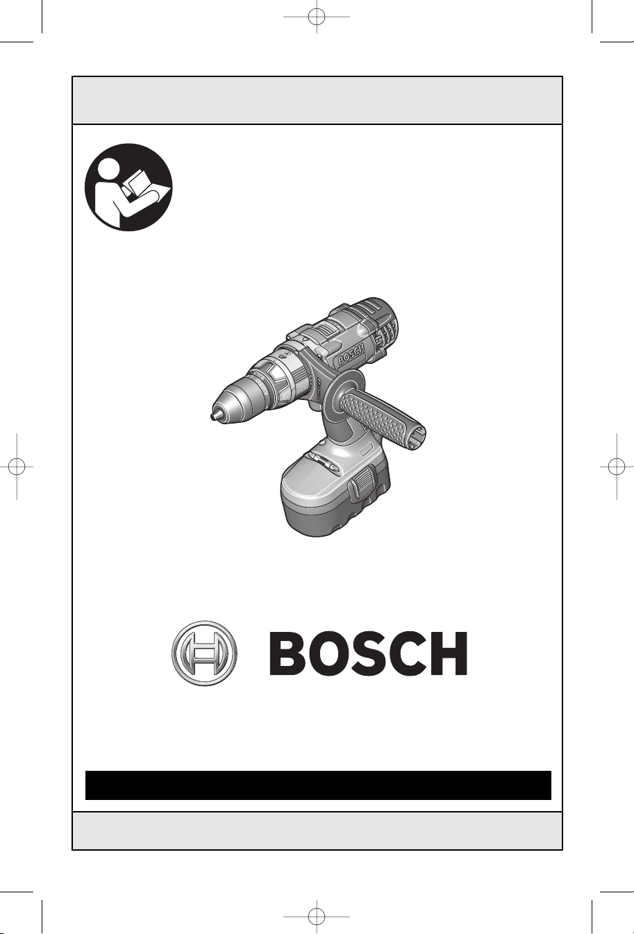
15614
15618
Call Toll Free for
Consumer Information
& Service Locations
1-877-BOSCH99 (1-877-267-2499) www.boschtools.com
For English Version Version française Versión en español
See page 2 Voir page 19 Ver la página
Pour obtenir des informations
et les adresses de nos centres
de service après-vente,
appelez ce numéro gratuit
Llame gratis para
obtener información
para el consumidor y
ubicaciones de servicio
36

BM 2609932519 11-06 12/1/06 2:36 PM Page 2
General Safety Rules
WARNING
!
in all of the warnings listed below refers to your mains-operated (corded) power tool or
battery-operated (cordless) power tool.
Read all instructions. Failure to follow all instructions listed below may
result in electric shock, fire and/or serious injury.
The term “power tool”
SAVE THESE INSTRUCTIONS
Work area safety
Keep work area clean and well lit.
Cluttered or dark areas invite accidents.
Do not operate power tools in explosive
atmospheres, such as in the presence of
flammable liquids, gases or dust.
tools create sparks which may ignite the dust
or fumes.
Keep children and bystanders away while
operating a power tool.
cause you to lose control.
Distractions can
Power
Electrical safety
Power tool plugs must match the outlet.
Never modify the plug in any way. Do not
use any adapter plugs with earthed
(grounded) power tools.
and matching outlets will reduce risk of
electric shock.
Avoid body contact with earthed or
grounded surfaces such as pipes,
radiators, ranges and refrigerators.
is an increased risk of electric shock if your
body is earthed or grounded.
Do not expose power tools to rain or wet
conditions.
increase the risk of electric shock.
Do not abuse the cord. Never use the cord
for carrying, pulling or unplugging the
power tool. Keep cord away from heat, oil,
sharp edges or moving parts.
entangled cords increase the risk of electric
shock.
When operating a power tool outdoors,
use an extension cord suitable for
outdoor use.
outdoor use reduces the risk of electric
shock.
Do not use AC only rated tools with a DC
power supply.
work, the electrical components of the AC
rated tool are likely to fail and create a
hazard to the operator.
Water entering a power tool will
Use of a cord suitable for
While the tool may appear to
Unmodified plugs
There
Damaged or
If operating the power tool in damp
locations is unavoidable a Ground Fault
Circuit Interrupter (GFCI) must be used to
supply the power to your tool.
personal protection devices like electrician’s
rubber gloves and footwear will further
enhance your personal safety.
GFCI and
Personal safety
Stay alert, watch what you are doing and
use common sense when operating a
power tool. Do not use a power tool while
you are tired or under the influence of
drugs, alcohol or medication.
inattention while operating power tools may
result in serious personal injury.
Use safety equipment. Always wear eye
protection.
mask, non-skid safety shoes, hard hat, or
hearing protection used for appropriate
conditions will reduce personal injuries.
Avoid accidental starting. Ensure the
switch is in the off-position before
plugging in.
finger on the switch or plugging in power
tools that have the switch on invites
accidents.
Remove any adjusting key or wrench
before turning the power tool on.
or a key left attached to a rotating part of the
power tool may result in personal injury.
Do not overreach. Keep proper footing
and balance at all times.
better control of the power tool in unexpected
situations.
Dress properly. Do not wear loose
clothing or jewelry. Keep your hair,
clothing and gloves away from moving
parts.
be caught in moving parts.
If devices are provided for the connection
of dust extraction and collection facilities,
ensure these are connected and properly
used.
related hazards.
Safety equipment such as dust
Carrying power tools with your
Loose clothes, jewelry or long hair can
Use of these devices can reduce dust-
-2-
A moment of
A wrench
This enables

BM 2609932519 11-06 12/1/06 2:36 PM Page 3
Keep handles dry, clean and free from oil
and grease.
c
ontrol the power tool.
Slippery hands cannot safely
Power tool use and care
Do not force the power tool. Use the
correct power tool for your application.
The correct power tool will do the job better
and safer at the rate for which it was
designed.
Do not use the power tool if the switch
does not turn it on and off.
that cannot be controlled with the switch is
dangerous and must be repaired.
Disconnect the plug from the power
source and/or the battery pack from the
power tool before making any
adjustments, changing accessories, or
storing power tools.
measures reduce the risk of starting the
power tool accidentally.
Store idle power tools out of the reach of
children and do not allow persons
unfamiliar with the power tool or these
instructions to operate the power tool.
Power tools are dangerous in the hands of
untrained users.
Maintain power tools. Check for
misalignment or binding of moving parts,
breakage of parts and any other condition
that may affect the power tools operation.
If damaged, have the power tool repaired
before use.
poorly maintained power tools.
Keep cutting tools sharp and clean.
Properly maintained cutting tools with sharp
cutting edges are less likely to bind and are
easier to control.
Use the power tool, accessories and tool
bits etc., in accordance with these
instructions and in the manner intended
for the particular type of power tool,
taking into account the working
conditions and the work to be performed.
Use of the power tool for operations different
from those intended could result in a
hazardous situation.
Many accidents are caused by
Any power tool
Such preventive safety
Use clamps or other practical way to
secure and support the workpiece to a
s
table platform.
o
r against your body is unstable and may
lead to loss of control.
H
olding the work by hand
Battery tool use and care
Ensure the switch is in the off position
before inserting battery pack.
battery pack into power tools that have the
switch on invites accidents.
Recharge only with the charger specified
by the manufacturer.
suitable for one type of battery pack may
create a risk of fire when used with another
battery pack.
Use power tools only with specifically
designated battery packs.
battery packs may create a risk of injury and
fire.
When battery pack is not in use, keep it
away from other metal objects like paper
clips, coins, keys, nails, screws, or other
small metal objects that can make a
connection from one terminal to another.
Shorting the battery terminals together may
cause burns or a fire.
Under abusive conditions, liquid may be
ejected from the battery, avoid contact. If
contact accidentally occurs, flush with
water. If liquid contacts eyes, additionally
seek medical help.
battery may cause irritation or burns.
Liquid ejected from the
Inserting the
A charger that is
Use of any other
Service
Have your power tool serviced by a
qualified repair person using only identical
replacement parts.
safety of the power tool is maintained.
Develop a periodic maintenance schedule
for your tool. When cleaning a tool be
careful not to disassemble any portion of
the tool since internal wires may be
misplaced or pinched or safety guard
return springs may be improperly
mounted.
gasoline, carbon tetrachloride, ammonia, etc.
may damage plastic parts.
Certain cleaning agents such as
This will ensure that the
SAVE THESE INSTRUCTIONS
-3-
BM 2609932519 11-06 12/1/06 2:36 PM Page 4
Safety Rules for Cordless Hammer Drills
Hold power tools by insulated gripping
surfaces when performing an operation
where the cutting tools may contact
hidden wiring.
make exposed metal parts of the tool “live”
and shock the operator.
Use clamps or other practical way to
secure and support the workpiece to a
stable platform.
or against your body is unstable and may
lead to loss of control.
Do not drill, fasten or break into existing
walls or other blind areas where electrical
wiring may exist.
unavoidable, disconnect all fuses or circuit
breakers feeding this worksite.
Wear ear protectors when using the tool for
extended periods.
high intensity noise can cause hearing loss.
Always use auxiliary handle for maximum
control over torque reaction or kick-back.
High torque 3/8" and larger chuck capacity
drills are equipped with auxiliary handles.
Always wear safety goggles or eye
protection when using this tool. Use a
dust mask or respirator for applications
which generate dust.
Use thick cushioned gloves and limit the
exposure time by taking frequent rest
periods.
action may be harmful to your hands and
arms.
Secure the material being drilled. Never
hold it in your hand or across legs.
Unstable support can cause the drill bit to
bind causing loss of control and injury.
Disconnect battery pack from tool before
making any assembly, adjustments or
changing accessories
safety measures reduce the risk of starting the
tool accidentally.
Position yourself to avoid being caught
between the tool or side handle and walls
or posts.
jammed in the work, the reaction torque of
the tool could crush your hand or leg.
If the bit becomes bound in the
workpiece, release the trigger
immediately, reverse the direction of
Contact with a “live” wire will
Holding the work by hand
If this situation is
Prolonged exposure to
Vibration caused by hammer-drill
. Such preventive
Should the bit become bound or
rotation and slowly squeeze the trigger to
back out the bit. Be ready for a strong
reaction torque. The drill body will tend to
twist in the opposite direction as the drill bit is
rotating.
Do not grasp the tool or place your hands
too close to the spinning chuck or drill
bit.
Your hand may be lacerated.
When installing a drill bit, insert the shank
of the bit well within the jaws of the
chuck.
enough, the grip of the jaws over the bit is
reduced and the loss of control is increased.
Do not use dull or damaged bits and
accessories.
greater tendency to bind in the workpiece.
When removing the bit from the tool avoid
contact with skin and use proper
protective gloves when grasping the bit
or accessory.
prolonged use.
Check to see that keys and adjusting
wrenches are removed from the drill
before switching the tool "ON".
wrenches can fly away at high velocity
striking you or a bystander.
Do not run the tool while carrying it at
your side.
entangled with clothing and injury may result.
!
grinding, drilling, and other construction
activities contains chemicals known to
cause cancer, birth defects or other
reproductive harm. Some examples of
these chemicals are:
• Lead from lead-based paints,
• Crystalline silica from bricks and cement
and other masonry products, and
• Arsenic and chromium from chemicallytreated lumber.
Your risk from these exposures varies,
depending on how often you do this type of
work. To reduce your exposure to these
chemicals: work in a well ventilated area, and
work with approved safety equipment, such
as those dust masks that are specially
designed to filter out microscopic particles.
If the bit is not inserted deep
Dull or damaged bits have a
Accessories may be hot after
A spinning drill bit could become
WARNING
Some dust created by
power sanding, sawing,
Keys or
-4-
BM 2609932519 11-06 12/1/06 2:36 PM Page 5
Battery/Charger
Before using battery charger, read all
instructions and cautionary markings on
(1) battery charger, (2) battery pack, and
(3) product using battery.
Use only the charger which accompanied
your product or direct replacement as
listed in the catalog or this manual.
substitute any other charger. Use only Bosch
approved chargers with your product. See
Functional Description and Specifications.
Do not disassemble charger or operate the
charger if it has received a sharp blow,
been dropped or otherwise damaged in
any way. Replace damaged cord or plugs
immediately.
damage may result in electric shock or fire.
Do not recharge battery in damp or wet
environment. Do not expose charger to
rain or snow. If battery case is cracked or
otherwise damaged, do not insert into
charger.
Charge only Bosch approved rechargeable
batteries.
Specifications. Other types of batteries may
burst causing personal injury and damage.
Charge battery pack in temperatures
above +40 degrees F (4 degrees C) and
below +105 degrees F (41 degrees C).
Incorrect reassembly or
Battery short or fire may result.
See Functional Description and
Do not
Store tool and battery pack in locations
where temperatures will not exceed 120
degrees F (49 degrees C).
to prevent serious damage to the battery
cells.
Battery leakage may occur under extreme
usage or temperature conditions. Avoid
contact with skin and eyes.
liquid is caustic and could cause chemical
burns to tissues. If liquid comes in contact
with skin, wash quickly with soap and water,
then with lemon juice or vinegar. If the liquid
contacts your eyes, flush them with water for
a minimum of 10 minutes and seek medical
attention.
Place charger on flat non-flammable
surfaces and away from flammable
materials when re-charging battery pack.
The charger and battery pack heat during
charging. Carpeting and other heat insulating
surfaces block proper air circulation which
may cause overheating of the charger and
battery pack. If smoke or melting of the case
are observed unplug the charger immediately
and do not use the battery pack or charger.
Use of an attachment not recommended or sold by Bosch may result in a
risk of fire, electric shock or injury to
persons.
This is important
The battery
Battery Care
WARNING
!
away from metal objects.
protect terminals from shorting
place batteries in a tool box or pocket with
nails, screws, keys, etc. Fire or injury may
result.
When batteries are not in
tool or charger, keep them
For example, to
DO NOT
WARNING
!
tool or charger, always place protective
cap onto end of battery pack.
cap, guards against terminal shorting.
DO NOT PUT BATTERIES INTO FIRE OR
EXPOSE TO HIGH HEAT.
explode.
To prevent fire or injury
when batteries are not in
Protective
They may
-5-
BM 2609932519 11-06 12/1/06 2:36 PM Page 6
Battery Disposal
WARNING
!
remove any component projecting from
the battery terminals.
r
esult. Prior to disposal, protect exposed
t
erminals with heavy insulating tape to
prevent shorting.
NICKEL-CADMIUM BATTERIES
If equipped with a nickel-cadmium battery, the
battery must be collected, recycled or
disposed of in an environmentally sound
manner.
industry program to collect and recycle these
batteries at the end of their useful life, when
taken out of service in the United States or
Do not attempt to disassemble the battery or
Fire or injury may
“The EPA certified RBRC
Battery Recycling Seal on the
nickel-cadmium (Ni-Cd)
battery indicates Robert
Bosch Tool Corporation is
voluntarily participating in an
Canada. The RBRC program provides a
convenient alterative to placing used Ni-Cd
batteries into the trash or the municipal
waste stream, which may be illegal in your
area.
Please call 1-800-8-BATTERY for information
on Ni-Cd battery recycling and disposal
bans/restrictions in your area, or return your
batteries to a Skil/Bosch/Dremel Service
Center for recycling. Robert Bosch Tool
Corporation’s involvement in this program is
part of our commitment to preserving our
environment and conserving our natural
resources.”
If equipped with a nickel-metal hydride
battery, the battery can be disposed of in a
municipal solid waste stream.
NICKEL-METAL HYDRIDE BATTERIES
-6-
A
0
A
A
0
A
BM 2609932519 11-06 12/1/06 2:36 PM Page 7
Symbols
IMPORTANT: Some of the following symbols may be used on your tool. Please study them
and learn their meaning. Proper interpretation of these symbols will allow you to operate the
tool better and safer.
Symbol Name Designation/Explanation
V Volts Voltage (potential)
A Amperes Current
Hz Hertz Frequency (cycles per second)
W Watt Power
kg Kilograms Weight
min
s Seconds Time
n
0
.../min Revolutions or reciprocation per minute Revolutions, strokes, surface speed,
0 Off position Zero speed, zero torque...
1, 2, 3, ... Selector settings Speed, torque or position settings.
I, II, III, Higher number means greater speed
Minutes Time
Diameter Size of drill bits, grinding wheels, etc.
No load speed Rotational speed, at no load
orbits etc. per minute
Infinitely variable selector with off Speed is increasing from 0 setting
Arrow Action in the direction of arrow
Alternating current Type or a characteristic of current
Direct current Type or a characteristic of current
Alternating or direct current Type or a characteristic of current
Class II construction Designates Double Insulated
Construction tools.
Earthing terminal Grounding terminal
Warning symbol Alerts user to warning messages
Ni-Cad RBRC seal Designates Ni-Cad battery recycling
program
This symbol designates
that this tool is listed by
Underwriters Laboratories.
This symbol designates
that this tool is listed by
the Canadian Standards
Association.
This symbol designates
that this tool is listed to
Canadian Standards by
Underwriters Laboratories.
This symbol designates that
this tool is listed by
Underwriters Laboratories,
and listed to Canadian
Standards by Underwriters
Laboratories.
This symbol
designates
that
this tool
complies
to NOM
Mexican
Standards.
-7-
BM 2609932519 11-06 12/1/06 2:36 PM Page 8
Functional Description and Specifications
!
WARNING
Disconnect battery pack from tool before making any assembly,
adjustments or changing accessories
reduce the risk of starting the tool accidentally.
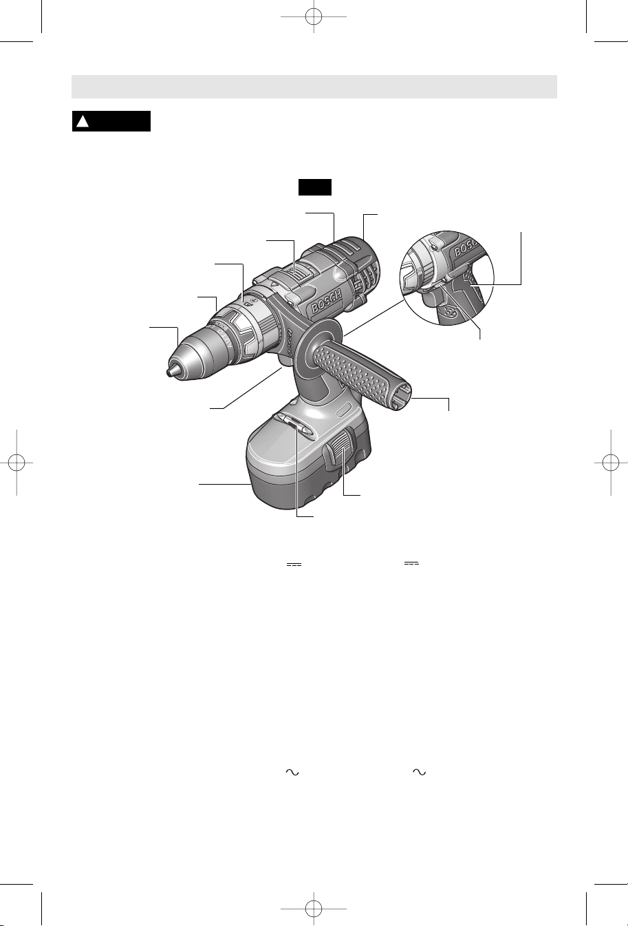
Cordless Hammer Drills
VENTILATION OPENINGS
GEAR SHIFTER
MODE SELECTOR RING
ADJUSTABLE CLUTCH
KEYLESS
CHUCK
VARIABLE SPEED
TRIGGER SWITCH
BATTERY PACK
FIG. 1
BIT STORAGE AREA
. Such preventive safety measures
BRUSH COVER
FORWARD/REVERSING
LEVER & TRIGGER LOCK
AUXILIARY
HANDLE
BATTERY RELEASE TABS
RUBBERIZED
GRIP
Model number 15614 15618
Voltage rating 14.4 V 18 V
No load speed 1 n
No load speed 2 n
Impact rate 29,000 BPM 31,000 BPM
0-450/min n00-500/min
0
0-1900/min n00-2000/min
0
Maximum Capacities
Chuck size
1/2" 1/2"
Screw sizes #16 x 3" #14 x 4"
Mild metal 1/2" 5/8"
Hard wood 1-1/4" 1-5/8"
Soft wood 1-3/4" 2"
Battery pack BAT040 BAT025, BAT026,
& BAT140 BAT180 & BAT181
Charger BC001-6 & BC016
BC003, 4, 6, & BC016
BC130 & BC230 BC130 & BC230
Voltage rating
120 V 60 Hz
120 V 60 Hz
BC006 charger requires 12 V DC input
NOTE: ONLY USE CHARGERS LISTED ABOVE
-8-
BM 2609932519 11-06 12/1/06 2:36 PM Page 9
Operating Instructions
VARIABLE SPEED CONTROLLED
Your tool is equipped with a variable speed
trigger switch. The tool can be turned "ON" or
"OFF" by squeezing or releasing the trigger.
The speed can be adjusted from the minimum
to maximum nameplate RPM by the pressure
you apply to the trigger. Apply more pressure
to increase the speed and release pressure to
decrease speed (Fig. 1).
!
WARNING
accidental starts and accidental discharge.
Your tool is equipped with a forward/
reversing lever and trigger lock located above
the trigger (Fig. 2). This lever was designed
for changing rotation of the bit, and for locking
the trigger in an “OFF” position.
For forward rotation, (with chuck pointed
away from you) move the lever to the far left.
Your tool is equipped with two separate gear
ranges, low gear and high gear. Low gear
provides high-torque and slower drilling
speeds for heavy duty work or for driving
screws. High gear provides faster speeds for
drilling lighter work. To change speeds slide
switch, to the high or low position (Fig. 1).
ATTENTION: If your tool appears to be
running, but the chuck will not turn, check to
make sure the gear shifting switch is pushed
fully into desired setting.
Your tool features 26 clutch settings. Output
torque will increase as the clutch ring, is
rotated from 1 to 25. The drill “ ” position
will lock up the clutch to permit drilling and
driving heavyduty work, and also enables bits
to be changed quickly and easily in the
keyless chuck (Fig. 3).
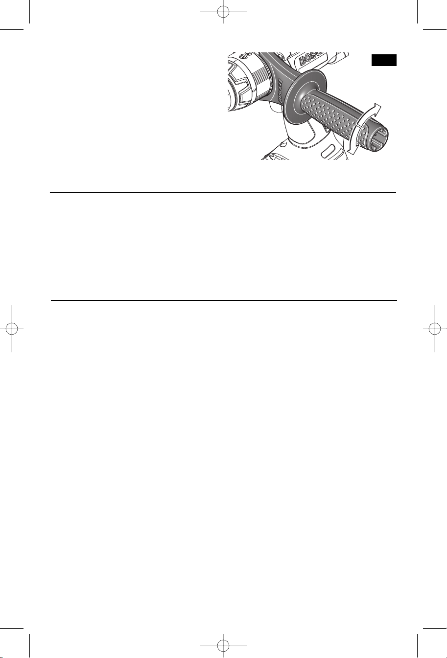
DRILL/HAMMER DRILL SELECTOR RING
The selector ring allows the tool to be set for
various drilling/hammer drilling applications.
Rotate the selector dial right or left
depending on the below applications (Fig. 4).
TRIGGER SWITCH
FORWARD/REVERSING
LEVER & TRIGGER LOCK
After tool use, lock trigger in
“OFF” position to help prevent
GEAR SHIFTING
ADJUSTABLE CLUTCH
Drill only action: For drilling in woods,
metals, plastics or other non concrete
materials.
For reverse rotation move the lever to the far
right. To activate trigger lock move lever to
the center off position.
CAUTION
!
comes to a complete stop.
rotation of the chuck can cause damage to
the tool.
Drill with hammer action: For drilling in
concrete, asphalt, tile or other similar
hard materials.
The hammer drill position overrides the clutch
for hammer drilling.
FIG. 3
Do not change direction of
rotation until the tool
Shifting during
ADJUSTABLE
CLUTCH
FIG. 4
MODE
SELECTOR
RING
-9-
FIG. 2
E
BM 2609932519 11-06 12/1/06 2:36 PM Page 10
W
hen the trigger switch is released it
activates the brake to stop the chuck quickly.
This is especially useful in the repetitive
driving and removal of screws.
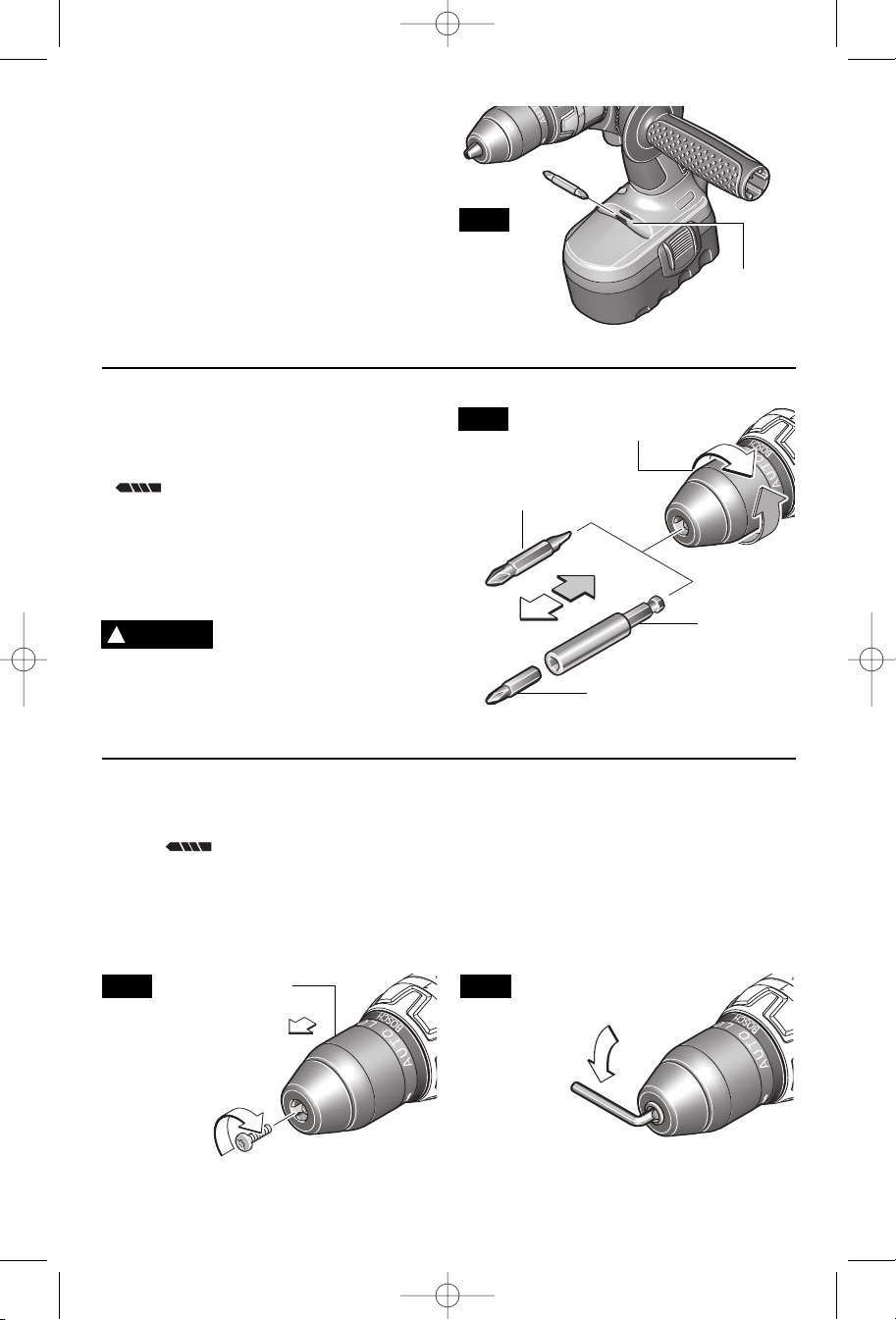
Your tool is equipped with a bit and storage
area that is conveniently located in the handle
base where it is always handy and unlikely to
get lost or misplaced (Fig. 5).
Move reverse switch lever to the center
“OFF” position. Remove battery pack and
rotate the clutch ring to the drill bit symbol
“ ”. Rotate the chuck sleeve counterclockwise viewing from chuck end, and open
chuck to approximate drill bit diameter. Insert
a clean bit up to the drill bit flutes for small
bits, or as far as it will go for large bits. Close
chuck by rotating the chuck sleeve clockwise
and securely tighten by hand (Fig. 6).
WARNING
!
chuck to loosen or tighten bit.
or hand injury is possible if attempting to
grasp the spinning chuck.
BRAKE
BIT STORAGE AREA
INSERTING BITS
Do not use the power of
the drill while grasping
Friction burn
FIG. 5
FIG. 6
SCREWDRIVER
BIT
BIT
STORAGE
AREA
CHUCK SLEEVE
BIT
HOLDER
SCREWDRIVER BIT
Rotate the clutch ring to the drill bit
symbol “ ”. Open the chuck all the way,
remove left-hand thread screw inside chuck
by turning it clockwise (Fig. 7).
Insert the short arm of a 1/2" hex key wrench
and close jaws on flats of wrench (Fig. 8).
Strike long arm of wrench sharply
FIG. 7
REMOVING CHUCK
CHUCK SLEEVE
counterclockwise, remove wrench and
unthread chuck from spindle.
INSTALLING CHUCK
Always keep the spindle threads, the threads
of the chuck and securing screw free of
debris. To install a chuck, reverse “removing
the chuck” procedure.
FIG. 8
-10-
BM 2609932519 11-06 12/1/06 2:36 PM Page 11
The tool must be supported with the auxiliary
AUXILIARY HANDLE
handle, which can be swiveled 360˚. To
reposition and/or swivel the handle, loosen
the hand grip, move the handle to the
desired position along the barrel and
securely retighten the hand grip (Fig. 9).
RELEASING AND INSERTING BATTERY PACK
Release battery pack from tool by pressing
on both sides of the battery release tabs and
pull downwards. Before inserting battery
pack, remove protective cap from battery
pack (Fig. 10).
FIG. 9
To insert battery, align battery and slide
battery pack into tool until it locks into
position. Do not force.
IMPORTANT CHARGING NOTES
1. The battery pack accepts only about 80% of
its maximum capacity with its first few charge
cycles. However, after the first few charge
cycles, the battery will charge to full capacity.
The charger was designed to fast charge
2.
the battery only when the battery temperature
is between 40˚F (4˚C) and 105˚F (41˚C).
3. A substantial drop in operating time per
charge may mean that the battery pack is
nearing the end of its life and should be
replaced.
4. If you anticipate long periods (i.e. a month
or more) of non-use of your tool, it is best to
run your tool down until it is fully discharged
before storing your battery pack. After a long
period of storage, the capacity at first recharge
will be lower. Normal capacity will be restored
in two or three charge/discharge cycles.
Remember to unplug charger during storage
period.
5. If battery does not charge properly:
a. Check for voltage at outlet by plugging
in some other electrical device.
Check to see if outlet is connected to a
b.
light switch which turns power “off” when lights
are turned off.
c. Check battery pack terminals for dirt.
Clean with cotton swab and alcohol if
necessary.
d. If you still do not get proper charging,
take or send tool, battery pack and charger to
your local Bosch Service Center. See “Tools,
Electric” in the Yellow Pages for names and
addresses.
Note: Use of chargers or battery packs not
sold by Bosch will void the warranty.
-11-
BM 2609932519 11-06 12/1/06 2:36 PM Page 12
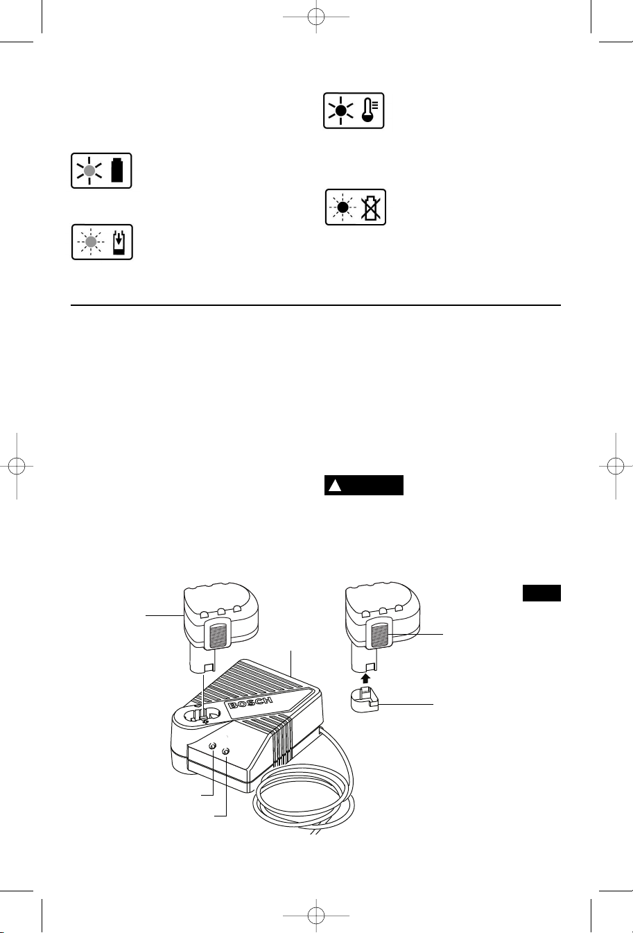
CHARGING BATTERY PACK (30 MINUTE SINGLE BAY-BC130)
INDICATORS, SYMBOLS AND MEANING
If the indicator lights are “OFF”, the charger
is not receiving power from power supply
outlet.
If the green indicator light is
“ON”, the charger is plugged in
but the battery pack is not
charger will switch to trickle charge, until a
suitable temperature is reached, at which
time the charger will switch automatically to
fast-charging.
inserted, or the battery pack is fully charged
and is being trickle charged.
If the green indicator light is
“BLINKING”, the battery pack is
being fast-charged. Fastcharging will automatically stop when the
battery pack is fully charged.
contacts of the charger or battery pack are
contaminated. Clean the contacts of the
charger or battery pack only as directed in
these operating instructions or those
supplied with your tool or battery pack.
If the red indicator light is “ON”,
the battery pack is too hot or
c
old for fast-charging. The
If the red indicator light is
“BLINKING”, the battery pack
cannot accept a charge or the
Plug charger cord into your standard power
outlet. Before inserting battery pack, remove
protective cap, then insert battery pack into
charger (Fig. 10).
The charger’s green indicator light will begin to
“BLINK”. This indicates that the battery is
receiving a fast charge. Fast-charging will
automatically stop when the battery pack is
fully charged.
When the indicator light stops “BLINKING”
(and becomes a steady green light) fast
charging is complete.
The battery pack may be used even though
the light may still be blinking. The light may
require more time to stop blinking depending
on temperature. When you begin the charging
process of the battery pack, a steady red light
could also mean the battery pack is too hot or
too cold.
BATTERY
PACK
CHARGER
The purpose of the green light is to indicate
that the battery pack is fast-charging. It does
not indicate the exact point of full charge. The
light will stop blinking in less time if the battery
pack was not completely discharged.
When charging several batteries in sequence,
the charge time may slightly increase.
When the battery pack is fully charged,
unplug the charger (unless you're charging
another battery pack) and slip the battery
pack back into the tool.
WARNING
!
To prevent fire or injury
when batteries are not in
tool or charger, always place protective cap
onto end of battery pack.
Protective cap,
guards against terminal shorting.
FIG. 10
BATTERY PACK
RELEASE TABS
PROTECTIVE
CAP
RED LIGHT
GREEN LIGHT
-12-
BM 2609932519 11-06 12/1/06 2:36 PM Page 13
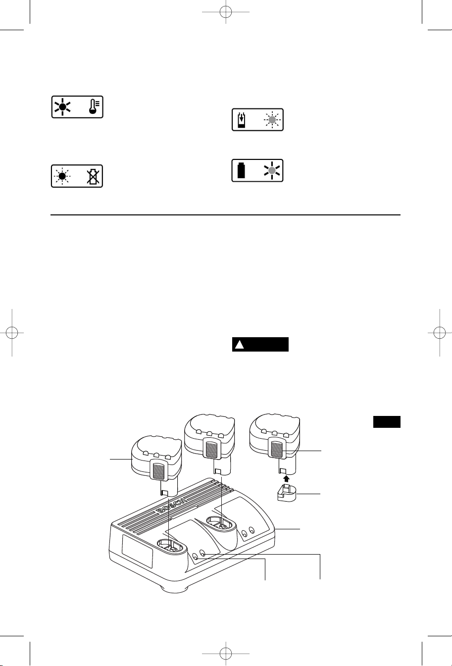
CHARGING BATTERY PACK (30 MINUTE DUAL BAY-BC230)
INDICATORS, SYMBOLS AND MEANING
If the indicator lights are “OFF”, the charger is
not receiving power from power supply outlet.
If the red indicator light is “ON”,
contaminated. Clean the contacts of the
charger or battery pack only as directed in
these operating instructions or those supplied
with your tool or battery pack.
the battery pack is too hot or
cold for fast-charging. The
charger will switch to trickle charge, until a
suitable temperature is reached, at which time
the charger will switch automatically to fastcharging.
charging will automatically stop when the
battery pack is fully charged.
If the red indicator light is
“BLINKING”, the battery pack
contacts of the charger or battery pack are
cannot accept a charge or the
inserted, or the battery pack is fully charged
and is being trickle charged.
If the green indicator light is
“
BLINKING”, the battery pack
is being fast-charged. Fast-
If the green indicator light is
“ON”, the charger is plugged in
but the battery pack is not
Plug charger cord into your standard power
outlet. Before inserting battery pack, remove
protective cap, then insert battery pack into
charger (Fig. 11).
The charger’s green indicator light will begin to
“BLINK”. This indicates that the battery is
receiving a fast charge. Fast-charging will
automatically stop when the battery pack is fully
charged.
When the indicator light stops “BLINKING” (and
becomes a steady green light) fast charging is
complete.
The battery pack may be used even though the
light may still be blinking. The light may require
more time to stop blinking depending on
temperature. When you begin the charging
process of the battery pack, a steady red light
could also mean the battery pack is too hot or
too cold.
BATTERY
PACK
The purpose of the green light is to indicate that
the battery pack is fast-charging. It does not
indicate the exact point of full charge. The light
will stop blinking in less time if the battery pack
was not completely discharged.
When charging several batteries in sequence,
the charge time may slightly increase.
When the battery pack is fully charged, unplug
the charger (unless you're charging another
battery pack) and slip the battery pack back
into the tool.
WARNING
!
To prevent fire or injury
when batteries are not in
tool or charger, always place protective
cap onto end of battery pack.
Protective
cap, guards against terminal shorting.
FIG. 11
BATTERY PACK
RELEASE TABS
PROTECTIVE
CAP
-13-
RED LIGHT
CHARGER
GREEN LIGHT
BM 2609932519 11-06 12/1/06 2:36 PM Page 14
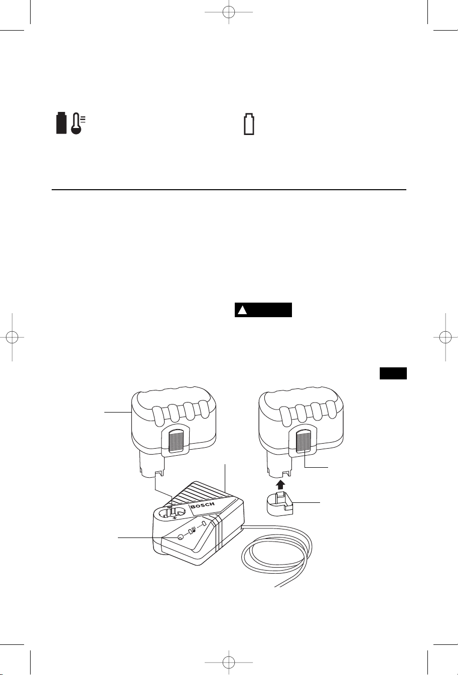
CHARGING BATTERY PACK (1 HOUR CHARGER)
INDICATORS, SYMBOLS AND MEANING
If the indicator lights are “OFF”, the charger
is not receiving power from power supply
outlet.
switch to trickle charge, until a suitable
temperature is reached, at which time the
charger will switch automatically to fastcharging.
If the green indicator light is “ON”,
the charger is plugged in but the
battery pack is not inserted, or the
battery pack is fully charged and is being
trickle charged, or the battery pack is too hot
will automatically stop when the battery pack
is fully charged.
or cold for fast-charging. The charger will
If the green indicator light is
“BLINKING”, the battery pack is
being fast-charged. Fast-charging
Plug charger cord into your standard power
outlet. Before inserting battery pack, remove
protective cap, then insert battery pack into
charger (Fig. 12).
The charger’s green indicator will begin to
“BLINK”. This indicates that the battery is
receiving a fast charge. Fast-charging will
automatically stop when the battery pack is
fully charged.
When the indicator light stops “BLINKING”
(and becomes a steady green light) fast
charging is complete.
When you begin the charging process of the
battery pack, a steady green light could also
mean the battery pack is too hot or too cold.
BATTERY
PACK
CHARGER
The purpose of the light is to indicate that the
battery pack is fast-charging. It does not
indicate the exact point of full charge. The
light will stop blinking in less time if the
battery pack was not completely discharged.
When the battery pack is fully charged,
unplug the charger (unless you're charging
another battery pack) and slip the battery
pack back into the tool handle.
WARNING
!
To prevent fire or injury
when batteries are not in
tool or charger, always place protective cap
onto end of battery pack.
Protective cap,
guards against terminal shorting.
FIG. 12
BATTERY PACK
RELEASE TABS
PROTECTIVE
CAP
INDICATOR
LIGHT
-14-
BM 2609932519 11-06 12/1/06 2:36 PM Page 15
Operating Tips
The purpose of the tether hook is to secure
the tool when working on ladders,
s
caffolding, or elevated heights to prevent
the tool from hitting the ground if accidentally
dropped. For best results, it is
recommended to use 1/4" braided nylon rope
or similar material.
You will extend the life of your bits and do
neater work if you always put the bit in
contact with the work before pulling the
trigger. During the operation, hold the tool
firmly and exert light, steady pressure. Too
much pressure at low speed will stall the tool.
Too little pressure will keep the bit from
cutting and cause excess friction by sliding
over the surface. This can be damaging to
both tool and bit.
TETHER HOOK
The trigger controlled variable speed feature
will eliminate the need for center punches in
h
ard materials. The variable speed trigger
allows you to slowly increase RPM. By using
a slow starting speed, you are able to keep
the bit from “wandering”. You can increase
the speed as the bit “bites” into the work by
squeezing the trigger.
Variable speed drills will double as a power
screwdriver by using a screwdriver bit in the
drill mode. The technique is to start slowly,
increasing the speed as the screw runs
down. Set the screw snugly by slowing to a
stop. Prior to driving screws, pilot and
clearance holes should be drilled.
DRILLING WITH VARIABLE SPEED
DRIVING WITH VARIABLE SPEED
FASTENING WITH SCREWS
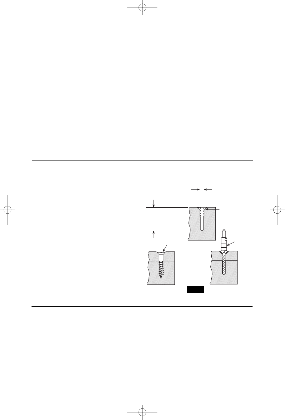
This procedure shown in (Fig. 13) will enable
you to fasten materials together with your
Cordless Drill/Screwdriver without stripping,
splitting or separating the material.
First, clamp the pieces together and drill the
first hole 2/3 the diameter of the screw. If the
material is soft, drill only 2/3 the proper
length. If it is hard, drill the entire length.
Second, unclamp the pieces and drill the
second hole the same diameter as the screw
shank in the first or top piece of wood.
Third, if flat head screw is used, countersink
the hole to make the screw flush with the
surface. Then, simply apply even pressure
when driving the screw. The screw shank
clearance hole in the first piece allows the
screw head to pull the pieces tightly together.
The adjustable screw drill accessory will do
all of these operations quickly and easily.
DRILL BITS
Always inspect drill bits for excessive wear. Use
only bits that are sharp and in good condition.
TWIST BITS: Available with straight and
reduced shanks for wood and light duty metal
drilling. High speed bits cut faster and last
longer on hard materials.
CARBIDE TIPPED BITS: Used for drilling
stone, concrete, plaster, cement and other
Screw drills are available for screw sizes No.
6, 8, 10 and 12.
FASTENING WITH
SCREWS
1. Drill 2/3 diameter and
2/3 of screw length for
soft materials, full
length for hard
materials.
Screw
Apply a slight
even pressure
when driving
screws.
2. Drill same
diameter as
screw shank.
3. Countersink
same diameter
as screw head.
Adjustable
Screw
Drill
FIG. 13
unusually hard nonmetals. Use continuous
heavy feed pressure when employing carbide
tip bits.
DRILLING WOOD
Be certain workpiece is clamped or anchored
firmly. Always apply pressure in a straight line
with the drill bit. Maintain enough pressure to
keep the drill “biting”.
-15-
BM 2609932519 11-06 12/1/06 2:36 PM Page 16
When drilling holes in wood, twist bits can be
used. Twist bits may overheat unless pulled out
frequently to clear chips from flutes.
Use a “back-up” block of wood for work that is
likely to splinter, such as thin materials.
You will drill a cleaner hole if you ease up on
the pressure just before the bit breaks through
the wood. Then complete the hole from the
back side.
There are two rules for drilling hard materials.
First, the harder the material, the greater the
pressure you need to apply to the tool. Second,
the harder the material, the slower the speed.
WARNING
!
safe operating speed is not exceeded by the
nameplate speed of the tool. Do not exceed
the recommended wheel diameter.
Fine sanding and polishing require “touch”.
Select the most efficient speed.
When using polishing bonnets, always be sure
the excess string that secures the bonnet is
tucked well within the bonnet during operation.
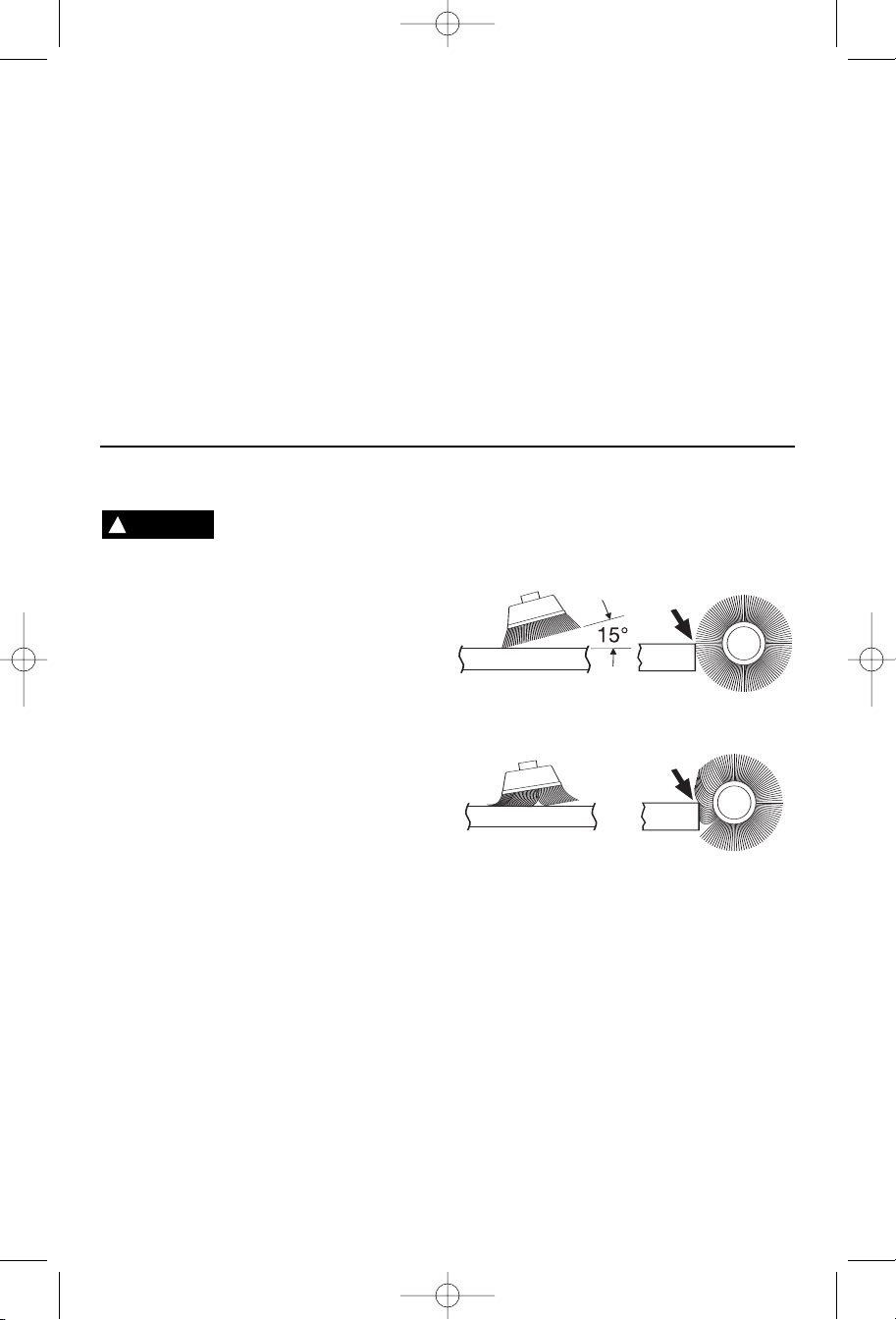
Work with brushes requires high speeds.
1. Remember, the tips of a wire brush do the
work. Operate the brush with the lightest
pressure so only the tips of the wire come in
contact with the work.
2. If heavier pressures are used, the wires
will be overstressed, resulting in a wiping
action; and if this is continued, the life of the
brush will be shortened due to wire fatigue.
3. Apply the brush to the work in such a way
that as much of the brush face as possible is
in full contact with the work. Applying the
side or edge of the brush to the work will
DRILLING METAL
Before using an accessory,
be certain that its maximum
SANDING AND POLISHING
WIRE BRUSHES
BRUSHING PRESSURE
Here are a couple of tips for drilling in metal.
Lubricate the tip of the bit occasionally with
cutting oil except when drilling soft metals such
as aluminum, copper or cast iron. If the hole to
be drilled is fairly large, drill a smaller hole first,
then enlarge to the required size, it’s often
faster in the long run. Maintain enough
p
ressure to assure that the bit does not just
spin in the hole. This will dull the bit and greatly
shorten its life.
Soft materials such as brick are relatively easy
to drill. Concrete however, will require much
more pressure to keep the bit from spinning. Be
sure to use carbide tip bits for all masonry work.
result in wire breakage and shortened brush
life.
INCORRECT: Excessive pressure can cause wire breakage.
Variable speed control must be used with
caution for driving nuts and bolts with socket
set attachments. The technique is to start
slowly, increasing speed as the nut or bolt runs
down. Set the nut or bolt snugly by slowing the
drill to a stop. If this procedure is not followed,
the tool will have a tendency to torque or twist
in your hands when the nut or bolt seats.
DRILLING MASONRY
CORRECT: Wire tips doing the work.
RUNNING NUTS AND BOLTS
-16-
BM 2609932519 11-06 12/1/06 2:36 PM Page 17
Maintenance
Service
WARNING
!
the replaceable carbon brushes.
Preventive maintenance performed by
unauthorized personnel may result in
misplacing of internal wires and
components which could cause serious
hazard.
performed by a Bosch Factory Service Center
or Authorized Bosch Service Station.
SERVICEMEN: Disconnect tool and/or
charger from power source before servicing.
Be alert for battery packs that are nearing
their end of life.
performance or significantly shorter running
time between charges then it is time to replace
the battery pack. Failure to do so can cause
the tool to operate improperly or damage the
charger.
Long term battery storage should be in the
discharged state.
and re-charge better when they are stored
discharged. Remember to fully re-charge
battery packs before using after prolonged
storage.
Your Bosch tool has been properly lubricated
and is ready for use.
The motor in your tool has been engineered for
many hours of dependable service. To
maintain peak efficiency of the motor, we
recommend it be examined every six months.
Only a genuine Bosch replacement motor
specially designed for your tool should be
used.
The brushes and commutator in your tool have
been engineered for many hours of
dependable service.
If your tool runs sporadically, loses power,
makes unusual noises or runs at a reduced
speed, check the brushes. To continue using
the tool in this condition will permanently
damage your tool.
Check both brushes. Usually the brushes will
not wear out simultaneously. If one brush is
worn out, replace both brushes.
We recommend that all tool service be
NO USER SERVICEABLE
PARTS INSIDE, except for
BATTERIES
If you notice decreased tool
Battery packs last longer
TOOL LUBRICATION
D.C. MOTORS
CARBON BRUSHES
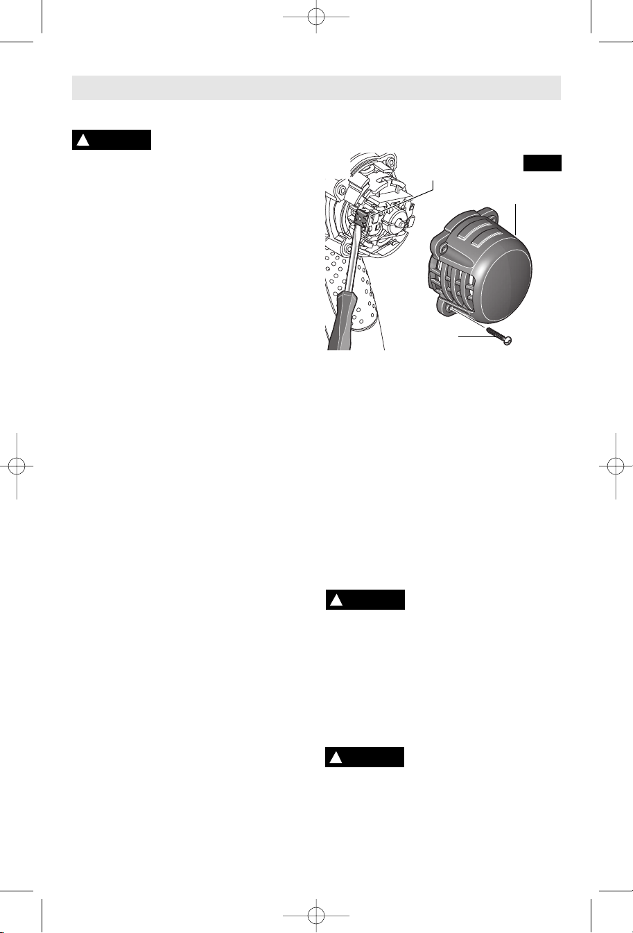
To check brushes: Disconnect battery pack
from tool. Remove brush cover at the rear part
of housing by loosening screws (Fig. 14).
BRUSH
HOLDER
SCREW
Insert a screwdriver or similar object into the
red notch of the carbon brush and lift out the
brushes; note which way they face, so that the
brushes can be returned to their original
position. Clean the brush holder openings with
compressed air or a clean cloth and replace
the brushes and brush covers.
After replacing brushes the tool should be run
at no-load and run it freely at full speed for 2
minutes before using the tool. This will allow
the brushes to “seat” properly and will give you
more hours of life from each set of brushes.
Only genuine Bosch replacement brushes
specially designed for your tool should be
used.
FIG. 14
BRUSH
COVER
Cleaning
!
WARNING
charger from the power supply before
cleaning.
effectively with compressed dry air.
wear safety goggles when cleaning tools
with compressed air.
Ventilation openings and switch levers must be
kept clean and free of foreign matter. Do not
attempt to clean by inserting pointed objects
through opening.
!
CAUTION
parts.
Some of these are: gasoline, carbon
tetrachloride, chlorinated cleaning solvents,
ammonia and household detergents that
contain ammonia.
To avoid accidents, always
disconnect the tool and/or
The tool may be cleaned most
Always
Certain cleaning agents and
solvents damage plastic
-17-
 Loading...