


Operating/Safety Instructions
Consignes de fonctionnement/sécurité
Instrucciones de funcionamiento
y seguridad
IMPORTANT: IMPORTANT : IMPORTANTE:
Read Before Using Lire avant usage Leer antes de usar
For English Parlez-vous français? ¿Habla español?
See page 2 Voir page 9 Ver página 16
Consumer Information
Renseignement des consommateurs
Información para el consumidor
Toll Free Number: Appel gratuit : Número de teléfono gratuito:
1-877-BOSCH99 (1-877-267-2499) http://www.boschtools.com.
1462VS
BM 3609929451 2/02 2/20/02 10:36 AM Page 1
Work Area
Keep your work area clean and well lit.
Cluttered benches and dark areas invite
accidents.
Do not operate power tools in explosive
atmospheres, such as in the presence of
flammable liquids, gases, or dust. Power
tools create sparks which may ignite the
dust or fumes.
Keep by-standers, children, and visitors
away while operating a power tool.
Distractions can cause you to lose control.
Electrical Safety
Double Insulated tools are equipped with a
polarized plug (one blade is wider than the
other.) This plug will fit in a polarized
outlet only one way. If the plug does not fit
fully in the outlet, reverse the plug. If it still
does not fit, contact a qualified electrician
to install a polarized outlet. Do not change
the plug in any way. Double Insulation
eliminates the need for the three wire
grounded power cord and grounded power
supply system. Before plugging in the tool,
be certain the outlet voltage supplied is
within the voltage marked on the nameplate.
Do not use “AC only” rated tools with a DC
power supply.
Avoid body contact with grounded
surfaces such as pipes, radiators, ranges
and refrigerators. There is an increased
risk of electric shock if your body is
grounded. If operating the power tool in
damp locations is unavoidable, a Ground
Fault Circuit Interrupter must be used to
supply the power to your tool. Electrician’s
rubber gloves and footwear will further
enhance your personal safety.
Don't expose power tools to rain or wet
conditions. Water entering a power tool will
increase the risk of electric shock.
Do not abuse the cord. Never use the
cord to carry the tools or pull the plug
from an outlet. Keep cord away from
heat, oil, sharp edges or moving parts.
Replace damaged cords immediately.
Damaged cords increase the risk of electric
shock.
When operating a power tool outside, use
an outdoor extension cord marked "W-A"
or "W." These cords are rated for outdoor
use and reduce the risk of electric shock.
Refer to “Recommended sizes of Extension
Cords” in the Accessory section of this
manual.
Personal Safety
Stay alert, watch what you are doing and
use common sense when operating a
power tool. Do not use tool while tired or
under the influence of drugs, alcohol, or
medication. A moment of inattention while
operating power tools may result in serious
personal injury.
Dress properly. Do not wear loose
clothing or jewelry. Contain long hair.
Keep your hair, clothing, and gloves away
from moving parts. Loose clothes, jewelry,
or long hair can be caught in moving parts.
Keep handles dry, clean and free from oil
and grease.
Avoid accidental starting. Be sure switch
is “OFF” before plugging in. Carrying tools
with your finger on the switch or plugging in
tools that have the switch “ON” invites
accidents.
Remove adjusting keys or wrenches
before turning the tool “ON”. A wrench or
a key that is left attached to a rotating part of
the tool may result in personal injury.
Do not overreach. Keep proper footing
and balance at all times. Proper footing
and balance enables better control of the
tool in unexpected situations.
Use safety equipment. Always wear eye
protection. Dust mask, non-skid safety
shoes, hard hat, or hearing protection must
be used for appropriate conditions.
Tool Use and Care
Use clamps or other practical way to
secure and support the workpiece to a
stable platform. Holding the work by hand
Read and understand all instructions. Failure to follow all instructions
listed below, may result in electric shock, fire and/or serious personal
injury.
SAVE THESE INSTRUCTIONS
-2-
!
WARNING
Power Tool Safety Rules
BM 3609929451 2/02 2/20/02 10:36 AM Page 2

-3-
Safety Rules for Tappers
Hold tool by insulated gripping surfaces
when performing an operation where the
tool may contact hidden wiring or its own
cord. Contact with a “live” wire will make
exposed metal parts of the tool “live” and
shock the operator. Do not tap, fasten or
break into existing walls or other blind areas
where electrical wiring may exist. If this
situation is unavoidable, disconnect all fuses
or circuit breakers feeding this worksite.
Always hold the tool with both hands. If
the bit jams two hands will give you
maximum control over torque reaction or
kickback.
Secure the material being tapped. Never
hold it in your hand or across legs.
Unstable support can cause the drill bit to
bind causing loss of control and injury.
Never leave the trigger locked "ON".
Before plugging the tool in, check that the
trigger lock is "OFF". Accidental start-ups
could cause injury.
Position the cord clear of tapper. Do not
wrap the cord around your arm or wrist.
If you lose control and have the cord
wrapped around your arm or wrist, it may
entrap you and cause injury.
If the tapper becomes bound in the
workpiece, release the trigger
immediately, reverse the direction of
rotation and slowly squeeze the trigger to
back out the bit. Be ready for a strong
reaction torque. The tool body will tend to
twist in the opposite direction as the tapper
is rotating.
Do not use the switch "Lock-ON" feature
in situations where tap binding is likely.
(For example: just before the tap is ready to
break through the material, anytime when
using a “Hole Saw”, auger bits, etc.) When
the tap binds, the tapper body will twist or
kickback in opposite direction and the
release of the trigger "Lock-ON" may be
difficult.
or against your body is unstable and may
lead to loss of control.
Do not force tool. Use the correct tool for
your application. The correct tool will do
the job better and safer at the rate for which
it is designed.Do not use tool if switch
does not turn it “ON” or “OFF”. Any tool
that cannot be controlled with the switch is
dangerous and must be repaired.
Disconnect the plug from the power
source before making any adjustments,
changing accessories, or storing the tool.
Such preventive safety measures reduce the
risk of starting the tool accidentally.
Store idle tools out of reach of children
and other untrained persons. Tools are
dangerous in the hands of untrained users.
Maintain tools with care. Keep cutting
tools sharp and clean. Properly
maintained tools, with sharp cutting edges
are less likely to bind and are easier to
control. Any alteration or modification is a
misuse and may result in a dangerous
condition.
Check for misalignment or binding of
moving parts, breakage of parts, and any
other condition that may affect the tools
operation. If damaged, have the tool
serviced before using. Many accidents are
caused by poorly maintained tools. Develop
a periodic maintenance schedule for your
tool.
Use only accessories that are
recommended by the manufacturer for
your model. Accessories that may be
suitable for one tool, may become
hazardous when used on another tool.
Service
Tool service must be performed only by
qualified repair personnel. Service or
maintenance performed by unqualified
personnel could result in a risk of injury. For
example: internal wires may be misplaced or
pinched, safety guard return springs may be
improperly mounted.
When servicing a tool, use only identical
replacement parts. Follow instructions in
the Maintenance section of this manual.
Use of unauthorized parts or failure to follow
Maintenance Instructions may create a risk
of electric shock or injury. Certain cleaning
agents such as gasoline, carbon
tetrachloride, ammonia, etc. may damage
plastic parts.
BM 3609929451 2/02 2/20/02 10:36 AM Page 3

Be aware of the location and setting of
the switch "Lock-ON" button. If the switch
is locked "ON" during use, be ready for
emergency situations to switch it "OFF".
First pulling the trigger then immediately
releasing it without pressing the "Lock-ON"
button.
Do not use dull or damaged bits and
accessories. Dull or damaged bits have a
greater tendency to bind in the workpiece.
When removing the bit from the tool avoid
contact with skin and use proper
protective gloves when grasping the bit
or accessory. Accessories may be hot after
prolonged use.
Check to see that keys and adjusting
wrenches are removed from the tapper
before switching the tool “ON”. Keys or
wrenches can fly away at high velocity
striking you or a bystander.
Do not run the tool while carrying it at
your side. A spinning bit could become
entangled with clothing and injury may
result.
Some dust created by
power sanding, sawing,
grinding, drilling, and other construction
activities contains chemicals known to
cause cancer, birth defects or other
reproductive harm. Some examples of
these chemicals are:
• Lead from lead-based paints,
• Crystalline silica from bricks and cement
and other masonry products, and
• Arsenic and chromium from chemically-
treated lumber.
Your risk from these exposures varies,
depending on how often you do this type of
work. To reduce your exposure to these
chemicals: work in a well ventilated area,
and work with approved safety equipment,
such as those dust masks that are specially
designed to filter out microscopic particles.
-4-
!
WARNING
BM 3609929451 2/02 2/20/02 10:36 AM Page 4
-5-
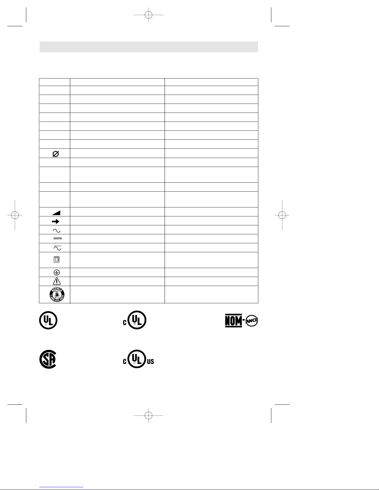
IMPORTANT: Some of the following symbols may be used on your tool. Please study them
and learn their meaning. Proper interpretation of these symbols will allow you to operate the
tool better and safer.
Symbol Name Designation/Explanation
V Volts Voltage (potential)
A Amperes Current
Hz Hertz Frequency (cycles per second)
W Watt Power
kg Kilograms Weight
min Minutes Time
s Seconds Time
Diameter Size of drill bits, grinding wheels, etc.
n
0
No load speed Rotational speed, at no load
.../min Revolutions or reciprocation per minute Revolutions, strokes, surface speed,
orbits etc. per minute
0 Off position Zero speed, zero torque...
1, 2, 3, ... Selector settings Speed, torque or position settings.
I, II, III, Higher number means greater speed
Infinitely variable selector with off Speed is increasing from 0 setting
Arrow Action in the direction of arrow
Alternating current Type or a characteristic of current
Direct current Type or a characteristic of current
Alternating or direct current Type or a characteristic of current
Class II construction Designates Double Insulated
Construction tools.
Earthing terminal Grounding terminal
Warning symbol Alerts user to warning messages
Ni-Cad RBRC seal Designates Ni-Cad battery recycling
program
Symbols
0
This symbol designates
that this tool is listed by
Underwriters Laboratories.
This symbol designates
that this tool is listed by
the Canadian Standards
Association.
This symbol designates
that this tool is listed to
Canadian Standards by
Underwriters Laboratories.
This symbol
designates
that
this tool
complies
to NOM
Mexican
Standards.
This symbol designates
that this tool is listed by
Underwriters Laboratories,
and listed to Canadian
Standards by Underwriters
Laboratories.
BM 3609929451 2/02 2/20/02 10:36 AM Page 5
-6-
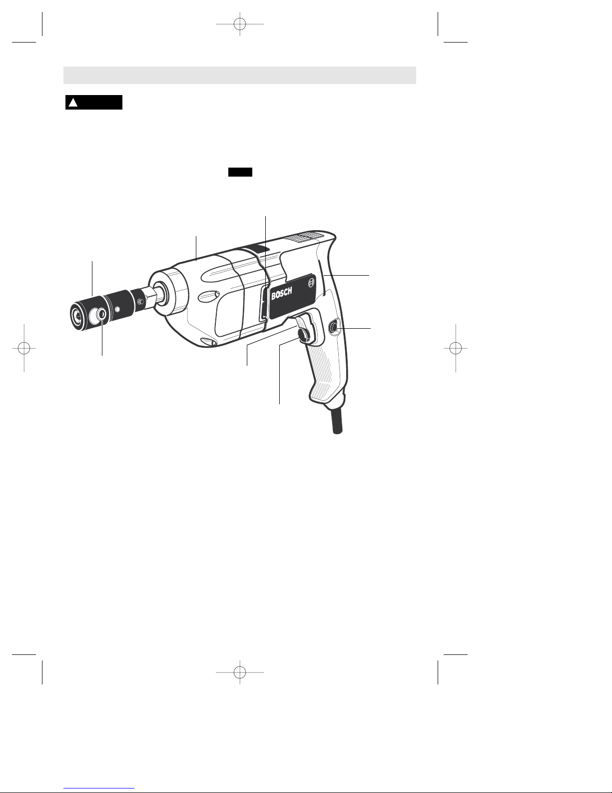
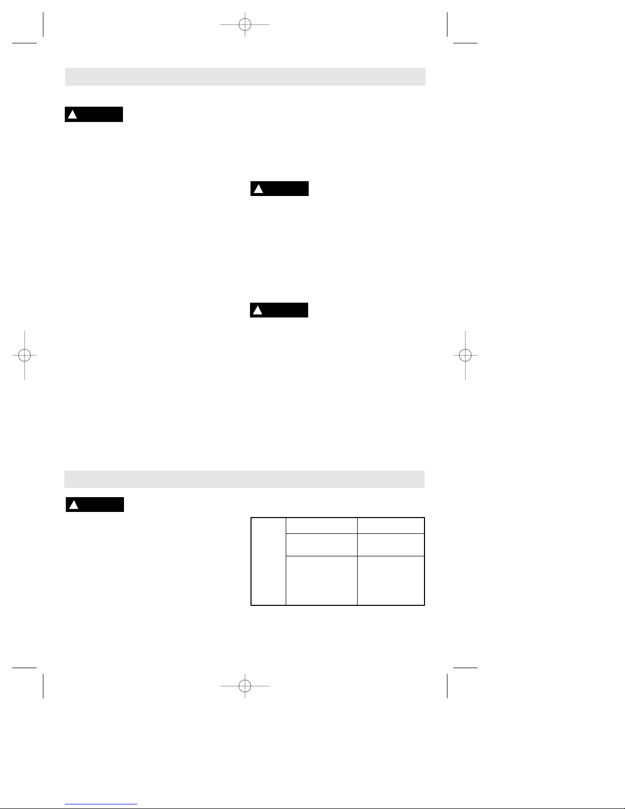
Functional Description and Specifications
Disconnect the plug from the power source before making any
assembly, adjustments or changing accessories. Such preventive safety
measures reduce the risk of starting the tool accidentally.
!
WARNING
Chuck Tap
Capacities Capacities
1/8
" - 3/8" 5/32" - 3/8"
NOTE: For tool specifications refer to the nameplate on your tool.
TRIGGER
MOTOR
HOUSING
Tapper
AIR
VENTS
FIG. 1
“LOCK-ON”
BUTTON
PRESET
SPEED ADJUSTING
DIAL
AIR
VENTS
CHUCK
SCREW
BM 3609929451 2/02 2/20/02 10:36 AM Page 6
-7-
Operating Instructions
TRIGGER CONTROLLED VARIABLE SPEED
Your tool is equipped with a variable speed
trigger switch. The tool speed can be
controlled from minimum to maximum
nameplate rated RPM by the pressure you
apply to the trigger. Apply more pressure to
increase the speed and release pressure to
decrease speed (Fig. 1).
"LOCK-ON" BUTTON
Your tool is also equipped with a “Lock-ON”
button located on the left side of the trigger
handle that allows for operation at maximum
RPM without holding the trigger (Fig. 1).
TO LOCK TRIGGER "ON": squeeze trigger,
depress button and release trigger.
TO UNLOCK THE TRIGGER: squeeze trigger
and release it without depressing the "LockON" button.
If the “Lock-ON” button is
continuously being depressed,
the trigger can not be released.
PRESET SPEED ADJUSTING DIAL
This feature enables you to preset the trigger
at desired speeds by rotating the dial on the
trigger to a higher or lower setting. Regardless
of the pressure applied on the trigger, the tool
will not operate any faster than maximum
speed setting selected.
OPERATING TIPS
Following a few simple tips will reduce the
wear on both the tool and the operator.
1. Support the tool so that steady even
pressure is applied to the tapping bit. The
pistol grip and contour body has been
designed for comfortable and natural
grasping. The tool can also be supported with
the use of an auxiliary handle (optional
accessory) which can be swielled to a
comfortable position and locked in place.
2. The two jaw chuck is suitable for square
shank tapping bits from 1/8” to 3/8” (3 to 9.5
mm). Insert the tapping bit within the jaws of
the chuck and securely tighten screw with the
allen key provided.
3. The gear box is designed for tapping righthand threads. Rotation in the right-hand
direction will begin immediately when
pressure is applied to the tap, and the trigger
switch is on. The feature of the chuck is that
the coulpling is self-aligning. This means the
tap will straighten itself along the axis of the
pilot hole if started slightly out-of-align.
4. Once the tap has reached the required
thread depth, the rotation can be reversed by
drawing back the tool which will automatically
reverse the direction of the tap.
5. Thread cutting oil must be used on every
hole when tapping.
6. Using the proper size pilot hole is as
important in tapping as any other factor. Do
not exceed the capacities recommended in
thsi manual for the tool. Use only taps that are
sharp and in good condition.
7. Select a speed suitable for the material
being tapped. Slow speeds are recommended
for large diameter taps. Highter speeds for
small diameter taps.
8. Common causes for broken taps are:
a) Starting tap out-of-align with hole axis.
b) Predrilled hole diameter too small.
c) Blunt or dull taps.
d) Inadequate lubrication
e) Misuse of the tool.
!
WARNING
BM 3609929451 2/02 2/20/02 10:36 AM Page 7
-8-
Maintenance
Service
Preventive maintenance
performed by unauthorized personnel may result in misplacing
of internal wires and components which
could cause serious hazard. We
recommend that all tool service be
performed by a Bosch Factory Service
Center or Authorized Bosch Service Station.
TOOL LUBRICATION
Your Bosch tool has been properly
lubricated and is ready to use. It is
recommended that tools with gears be
regreased with a special gear lubricant at
every brush change.
CARBON BRUSHES
The brushes and commutator in your tool
have been engineered for many hours of
dependable service. To maintain peak
efficiency of the motor, we recommend
every two to six months the brushes be
examined. Only genuine Bosch replacement
brushes specially designed for your tool
should be used.
BEARINGS
After about 300-400 hours of operation, or at
every second brush change, the bearings
should be replaced at Bosch Factory
Service Center or Authorized Bosch Service
Station. Bearings which become noisy (due
to heavy load or very abrasive material cutting) should be replaced at once to avoid
overheating or motor failure.
Cleaning
To avoid accidents always
disconnect the tool from
the power supply before cleaning or
performing any maintenance. The tool may
be cleaned most effectively with
compressed dry air. Always wear safety
goggles when cleaning tools with
compressed air.
Ventilation openings and switch levers must
be kept clean and free of foreign matter. Do
not attempt to clean by inserting pointed
objects through openings.
Certain cleaning agents
and solvents damage
plastic parts. Some of these are: gasoline,
carbon tetrachloride, chlorinated cleaning
solvents, ammonia and household
detergents that contain ammonia.
!
WARNING
!
WARNING
!
CAUTION
Accessories
If an extension cord is
necessary, a cord with
adequate size conductors that is capable
of carrying the current necessary for your
tool must be used. This will prevent
excessive voltage drop, loss of power or
overheating. Grounded tools must use 3wire extension cords that have 3-prong
plugs and receptacles.
NOTE: The smaller the gauge number, the
heavier the cord.
RECOMMENDED SIZES OF EXTENSION CORDS
120 VOLT ALTERNATING CURRENT TOOLS
!
WARNING
Tool’s
Ampere
Rating
Cord Size in A.W.G.
Wire Sizes in mm
2
3-6
6-8
8-10
10-12
12-16
18 16 16 14 .75 .75 1.5 2.5
18 16 14 12 .75 1.0 2.5 4.0
18 16 14 12 .75 1.0 2.5 4.0
16 16 14 12 1.0 2.5 4.0 —
14 12 — — — — — —
25 50 100 150 15 30 60 120
Cord Length in Feet Cord Length in Meters
BM 3609929451 2/02 2/20/02 10:36 AM Page 8

-9-
Vous devez lire et comprendre toutes les instructions. Lenon-respect, même
partiel, des instructions ci-après entraîne un risque de choc életrique, d'incendie
et/ou de blessures graves.
CONSERVEZ CES INSTRUCTIONS
Règles de Sécurité Générales
AVERTISSEMENT
!
Aire de travail
Veillez à ce que l'aire de travail soit propre et bien
éclairée. Le désordre et le manque de lumière
favorisent les accidents.
N'utilisez pas d'outils électriques dans une
atmosphère explosive, par exemple enprésence de
liquides, de gaz ou de poussières inflammables. Les
outils électriques créent des étincelles qui pourraient
enflammer les poussières ou les vapeurs.
Tenez à distance les curieux, les enfants et les
visiteurs pendant que vous travaillezavec un outil
électrique. Ils pourraient vous distraire et vous faire
faire une fausse manoeuvre.
Sécurité électrique
Les outils à double isolation sont équipés d'une fiche
polarisée (une des lames est pluslarge que l'autre),
qui ne peut se brancher que d'une seule façon dans
une prise polarisée. Si la fiche n'entre pas
parfaitement dans la prise, inversez sa position ; si
elle n'entre toujours pasbien, demandez à un
électricien qualifié d'installer une prise de courant
polarisée. Ne modifiez pas la fiche de l'outil. La
double isolation élimine le besoin d'un cordon
d'alimentationà trois fils avec mise à la terre ainsi que
d'une prise de courant mise à la terre. Avant de
brancher l'outil, assurez-vous que la tension de la prise
correspond, à celle indiquée sur la plaque signalétique.
N'utilisez pas d'outils prévus pour courant alternatif
seulement avec une source de courant continu.
Évitez tout contact corporel avec des surfaces mises à
la terre (tuyauterie, radiateurs, cuisinières,
réfrigérateurs, etc.). Le risque de choc électrique est
plus grand si votre corps est encontact avec la terre.Si
l'utilisation de l'outil électrique dans un endroit humide
est inévitable, un disjoncteur de fuite à la terre doit être
utilisé pour alimenter votre outil. Des chaussures et des
gants en caoutchouc d'électricien contribueront à
accroître davantage votre sécurité personnelle.
N'exposez pas les outils électriques à la pluie ou à
l'eau. La présence d'eau dans un outil électrique
augmente le risque de choc électrique.
Ne maltraitez pas le cordon. Ne transportez pas l'outil
par son cordon et ne débranchez pas la fiche en tirant
sur le cordon. N'exposez pas le cordon à la chaleur, à
des huiles, à des arêtes vives ou à des pièces en
mouvement. Remplacez immédiatement un cordon
endommagé. Un cordon endommagé augmente le
risque de choc électrique.
Lorsque vous utilisez un outil électrique à l'extérieur,
employez un prolongateur pour l'extérieur marqué «
W-A » ou « W ». Ces cordons sont faits pour être
utilisés à l'extérieur et réduisent le risque de choc
électrique. Reportez-vous aux « Dimensions
recommandées des cordons de rallonge » dans la
section Accessoires de ce manuel.
Sécurité des personnes
Restez alerte, concentrez-vous sur votre travail et
faites preuve de jugement. N'utilisez pas un outil
électrique si vous êtes fatigué ou sous l'influence de
drogues, d'alcool ou de médicaments. Un instant
d'inattention suffit pour entraîner des blessures graves.
Habillez-vous convenablement. Ne portez ni
vêtements flottants ni bijoux. Confinez les cheveux
longs. N'approchez jamais les cheveux, les
vêtements ou les gants des pièces en mouvement.
Des vêtements flottants, des bijoux ou des cheveux
longs risquent d'être happés par des pièces en
mouvement. Gardez les poignées sèches, propres et
exemptes d'huile et de graisse.
Méfiez-vous d'un démarrage accidentel. Avant de
brancher l'outil, assurez-vous que son interrupteur
est sur ARRÈT. Le fait de transporter un outil avec le
doigt sur la détente ou de brancher un outil dont
l'interrupteur est en position MARCHE peut mener tout
droit à un accident.
Enlevez les clés de réglage ou de serrage avant de
démarrer l'outil. Une clé laissée dans une pièce
tournante de l'outil peut provoquer des blessures.
Ne vous penchez pas trop en avant. Maintenez un bon
appui et restez en équilibre entout temps. Un bonne
stabilité vous permet de mieux réagir à une situation
inattendue.
Utilisez des accessoires de sécurité. Portez toujours
des lunettes ou une visière. Selon les conditions,
portez aussi un masque antipoussière, des bottes de
sécurité antidérapantes, un casque protecteur et/ou un
appareil antibruit.
Utilisation et entretien des outils
Immobilisez le matériau sur une surface stable au
moyen de brides ou de toute autre façon adéquate. Le
fait de tenir la pièce avec la main ou contre votre corps
offre une stabilité insuffisante et peut amener un
dérapage de l'outil.
Ne forcez pas l'outil. Utilisez l'outil approprié à la
tâche. L'outil correct fonctionne mieux et de façon plus
BM 3609929451 2/02 2/20/02 10:36 AM Page 9

Tenez l'outil par les surfaces isolées de préhension
en exécutant une opération au cours de laquelle
l'outil de coupe peut venir en contact avec les fils
cachés ou son propre cordon. Le contact avec un fil
sous tension rendra les pièces métalliques exposées
de l'outil sous tension et causera des chocs à
l'opérateur. Ne tarauder, fixez et ne rentrez pas dans
des murs existants ou autres endroits aveugles
pouvant abriter des fils électriques. Si cette situation
est inévitable, débranchez tous les fusibles ou les
disjoncteurs alimentant ce site.
Tenez toujours l’outil à deux mains. Si le taraud
venait à se coincer, vous serez plus à même de
maîtriser le couple de réaction ou le rebond de l’outil.
Assujettissez l'ouvrage à taraud. Ne le tenez jamais
dans votre main ou par-dessus vos jambes. Un
support instable peut faire gripper le taraud,
provoquant ainsi une perte de contrôle et des
blessures.
Ne tenez jamais la gâchette bloquée en position de
marche. Avant de brancher l'outil, assurez-vous
que le blocage de la gâchette est inhibé. Les mises
en marche accidentelles peuvent causer des
blessures.
Placez le cordon à l'écart du taraud en rotation.
N'enroulez pas le cordon autour de votre bras ou de
votre poignet. Si vous perdez contrôle et que le
cordon s'enroule autour de votre bras ou de votre
poignet, il peut vous emprisonner et vous blesser.
Si le taraud grippe dans l'ouvrage, relâchez la
gâchette immédiatement, inversez le sens de
rotation et appuyez lentement sur la gâchette pour
faire ressortir le taraud. Soyez prêt à un fort couple
de réaction. Le corps de la taraudeuse aura tendance
à tordre en sens opposé à mesure que le taraud
tourne.
N'utilisez pas le dispositif de blocage en position
de marche de l'interrupteur dans des situations où
le taraud est susceptible de gripper. (Par exemple :
immédiatement avant que le taraud ne soit prêt à
rentrer à travers le matériau, chaque fois que vous
utilisez une « scie à perforation », des mèches
hélicoïdales, etc.) Lorsque le taraud grippe, le corps
de la taraudeuse tord ou rebondit en sens opposé, et
il peut être difficile de relâcher le dispositif de blocage
en position de marche de la gâchette.
Soyez au courant de l'emplacement et de la
position du bouton de blocage en marche de la
gâchette. Si l'interrupteur est bloqué en marche
durant l'usage, soyez prêt, dans des cas d'urgence, à
le mettre à l'arrêt en appuyant d'abord sur la
gâchette, puis en la relâchant immédiatement sans
appuyer sur le bouton de blocage en marche.
-10-
Consignes de sécurité pour les taraudeuses
sécuritaire. Respectez aussi la vitesse de travail qui lui
est propre.
N'utilisez pas un outil si son interrupteur est bloqué.
Un outil que vous ne pouvez pas commander par son
interrupteur est dangereux et doit être réparé.
Débranchez la fiche de l'outil avant d'effectuer un
réglage, de changer d'accessoire oude ranger l'outil.
De telles mesures préventives de sécurité réduisent le
risque de démarrage accidentel de l'outil.
Rangez les outils hors de la portée des enfants et
d'autres personnes inexpérimentées. Les outils sont
dangereux dans les mains d'utilisateurs novices.
Prenez soin de bien entretenir les outils. Les outils de
coupe doivent être toujours bien affûtés et propres.
Des outils bien entretenus, dont les arêtes sont bien
tranchantes, sont moins susceptibles de coincer et plus
faciles à diriger.Toute altération ou modification
constitue un usage erroné et peut causer un danger.
Soyez attentif à tout désalignement ou coincement
des pièces en mouvement, à tout bris ou à toute autre
condition préjudiciable au bon fonctionnement de
l'outil. Si vous constatez qu'un outil est endommagé,
faites-le réparer avant de vous en servir. De
nombreux accidents sont causés par des outils en
mauvais état. Élaborez un calendrier d'entretien
périodique de votre outil.
N'utilisez que des accessoires que le fabricant
recommande pour votre modèle d'outil. Certains
accessoires peuvent convenir à un outil, mais être
dangereux avec un autre.
Réparation
La réparation des outils électriques doit être confiée
à un réparateur qualifié. L'entretien ou la réparation
d'un outil électrique par un amateur peut avoir des
conséquences graves. Ainsi, des fils internes peuvent
être mal placés ou pincés, des ressorts de rappel de
protecteur peuvent être montés erronément.
Pour la réparation d'un outil, n'employez que des
pièces de rechange d'origine. Suivez les directives
données à la section « Réparation » de ce manuel.
L'emploi de pièces non autorisées ou le non-respect
des instructions d'entretien peut créer un risque de
choc électrique ou de blessures. Certains agents
nettoyants tels qu'essence, tétrachlorure de carbone,
ammoniac, etc., peuvent abîmer les pièces en plastique.
BM 3609929451 2/02 2/20/02 10:36 AM Page 10

-11-
N'utilisez pas de forets et d'accessoires émoussés
ou endommagés. Les taraud émoussés ou
endommagés ont tendance à gripper dans l'ouvrage.
En retirant le foret de l'outil, évitez tout contact
avec la peau et utilisez des gants protecteurs
appropriés en saisissant le foret ou l'accessoire.
Les accessoires peuvent être chauds après une
utilisation prolongée.
Assurez-vous que les clés de serrage et de réglage
sont retirées de la outil avant de mettre l'outil en
marche. Les clés de serrage ou de réglage peuvent
être projetées à grande vitesse et frapper une
personne présente ou vous-même.
Ne faites pas fonctionner la perceuse en la portant
à votre côté. Un foret en rotation pourrait
s'emmêlever à vos vêtements, ce qui pourrait causer
des blessures.
Les travaux à la machine
tel que ponçage, sciage,
meulage, perçage et autres travaux du bâtiment
peuvent créer des poussières contenant des produits
chimiques qui sont des causes reconnues de cancer,
de malformation congénitale ou d’autres problèmes
reproductifs. Ces produits chimiques sont, par
exemple :
• Le plomb provenant des peintures à base de plomb,
• Les cristaux de silices provenant des briques et du
ciment et d’autres produits de maçonnerie, et
• L’arsenic et le chrome provenant des bois traités
chimiquement.
Le niveau de risque dû à cette exposition varie avec la
fréquence de ces types de travaux. Pour réduire
l’exposition à ces produits chimiques, il faut travailler
dans un lieu bien ventilé et porter un équipement de
sécurité approprié tel que certains masques à poussière
conçus spécialement pour filtrer les particules
microscopiques.
AVERTISSEMENT
!
BM 3609929451 2/02 2/20/02 10:36 AM Page 11

-12-
Symboles
Important : Certains des symboles suivants peuvent être utilisés sur votre outil. Veuillez les étudier et apprendre
leur signification. Une interprétation appropriée de ces symboles vous permettra d'utiliser l'outil de façon plus
efficace et plus sûre.
Symbole Nom Désignation/Explication
V Volts Tension (potentielle)
A Ampères Courant
Hz Hertz Fréquence (cycles par seconde)
W Watt Puissance
kg Kilogrammes Poids
min Minutes Temps
s Secondes Temps
Diamètre Taille des mèches de perceuse, meules,
etc.
n
0
Vitesse à vide Vitesse de rotation, à vide
.../min Tours ou mouvement alternatif par Tours, coups, vitesse en surface, orbites,
minute etc., par minute,
0 Position d'arrêt Vitesse zéro, couple zéro ...
1, 2, 3, ... Réglages du sélecteur Réglages de vitesse, de couple ou de
l, ll, lll, ... position. Un nombre plus élevé signifie
une vitesse plus grande.
Sélecteur variable à l'infini avec arrêt La vitesse augmente depuis le réglage 0
Flèche Action dans la direction de la flèche
Courant alternatif Type ou caractéristique du courant
Courant continu Type ou caractéristique du courant
Courant alternatif Type ou caractéristique du courant
ou continu
Construction classe II Désigne des outils construits avec double
isolation
Borne de terre borne de mise à la terre
Symbole d'avertissement Alerte l'utilisateur aux messages
d'avertissement.
Sceau Ni-Cad RBRCmc Désigne le programme de recyclage des piles
Ni-Cad.
0
Ce symbole signifie que cet
outil est approuvé par
Underwriters Laboratories.
Ce symbole signifie que cet
outil est approuvé par
l'Association canadienne de
normalisation.
Ce symbole signifie que
cet outil est approuvé
conformément aux normes
canadiennes par Underwriters
Laboratories.
Ce symbole
signifie que
cet outil se
conforme aux
normes
mexicaines
NOM.
Ce symbole signifie que cet outil
est approuvé par Underwriters
Laboratories et qu’il a été
homologué selon les normes
canadiennes par Underwriters
Laboratories.
BM 3609929451 2/02 2/20/02 10:36 AM Page 12

-13-
Description fonctionnelle et spécifications
Débranchez la fiche de la prise de courant avant d'effectuer quelque assemblage
ou réglage que ce soit ou de changer les accessoires. Ces mesures de sécurité
préventive réduisent le risque d'une mise en marche accidentelle de l'outil.
REMARQUE : Pour spécifications de l'outil, reportez-vous à la plaque signalétique de votre outil.
AVERTISSEMENT
!
Capacité Taille des
du mandrin tarauds
3mm - 9,5mm 3,9mm - 9,5mm”
GÂCHETTE
BOÎTIER
DU MOTEUR
Taraudeuse
ÉVENTS
FIG. 1
BOUTON DE
BLOCAGE EN
MARCHE
CADRAN
D'AJUSTEMENT DE
VITESSE PRÉRÉGLÉE
ÉVENTS
MANDRIN
VIS
BM 3609929451 2/02 2/20/02 10:36 AM Page 13

VITESSE VARIABLE COMMANDÉE PAR GÂCHETTE
Votre outil est équipée d’une gâchette à vitesse variable.
La vitesse de la outil peut être réglée de zéro au régime
maximum spécifié sur la plaque signalétique. La vitesse
s’ajuste par la pression que vous exercez sur la gâchette.
Exercez plus de pression pour augmenter la vitesse, et
relâchez la pression pour diminuer la vitesse (fig. 1).
BOUTON DE BLOCAGE EN MARCHE
La outil est également pourvue d’un bouton de blocage
en marche situé du côté gauche de la poignée de la
gâchette qui permet le fonctionnement au régime
maximum — sans devoir tenir la gâchette (fig. 1).
POUR BLOQUER L’INTERRUPTEUR EN MARCHE :
appuyez sur la gâchette, appuyez sur le bouton et
relâchez la gâchette
POUR DEBLOQUER L’INTERRUPTEUR : appuyez sur la
gâchette et relâchez-la sans appuyer sur le bouton de
blocage en marche.
Si l’utilisateur appuie
continuellement sur le
bouton de blocage en marche, la gâchette ne peut pas
être relâchée.
CADRAN D'AJUSTEMENT DE VITESSE PRÉRÉGLÉE
Cette fonction vous permet de prérégler la gâchette aux
vitesses désirées en tournant le cadran de la gâchette à
un réglage plus élevé ou plus bas. Quelle que soit la
pression exercée sur la gâchette, l'outil ne fonctionnera
pas à une vitesse supérieure au réglage maximal de
vitesse sélectionné.
CONSEILS D’UTILISATION
Suivez ces quelques conseils pour réduire l’usure de
l’outil et la fatigue de l’utilisateur.
1. Supportez l’outil de manière à pouvoir appliquer une
pression régulière sur le taraud. La poignée pistolet et le
corps profilé ont été conçus pour permettre de tenir
l’outil de manière confortable et naturelle. On peut
également supporter l’outil à l’aide d’une poignée
auxiliaire (accessoire en option) pivotante qui peut être
positionnée confortablement et bloquée en place.
2. Le mandrin à deux mors convient aux tarauds à queue
carrée de 1/8 po à 3/8 po (3 à 9,5 mm). Enfoncez le
taraud entre les mors du mandrin et serrez fermement la
vis avec la clé Allen fournie.
3. La boîte de vitesses est conçue pour fileter à droite. Si
la gâchette est enfoncée, l’outil commence à tourner à
droite dès qu’on applique une pression sur le taraud. La
caractéristique du mandrin est qu’il est à alignement
automatique. C’est à dire que le taraud se redresse
automatiquement pour s’aligner dans l’axe de l’avanttrou si on démarre légèrement mal aligné.
4. Une fois que le taraud a atteint la profondeur de
filetage requise, on peut inverser automatiquement le
sens de rotation en tirant sur l’outil.
5. Il convient d’utiliser de l’huile de coupe lors du
taraudage de chaque trou.
6. Un des points importants pour réussir un taraudage
est de percer l’avant trou au diamètre correct. Ne
dépassez pas les capacités conseillées dans ce mode
d’emploi. Utilisez uniquement des tarauds affûtés et en
bon état.
7. Choisissez une vitesse adaptée au matériau à
tarauder. Les vitesses lentes sont recommandées pour
les tarauds de grand diamètre tandis que les vitesses
rapides sont réservées aux tarauds de petit diamètre.
8. Les causes habituelles de casse de tarauds sont :
a) Démarrage du taraud alors qu’il est mal aligné sur
l’axe du trou.
b) Diamètre de l’avant-trou trop petit.
c) Taraud émoussé ou épointé.
d) Lubrification inadéquate.
e) Utilisation incorrecte de l’outil.
-14-
Consignes de fonctionnement
AVERTISSEMENT
!
BM 3609929451 2/02 2/20/02 10:36 AM Page 14

-15-
Maintenance
Entretien
L’entretien préventif
effectué par des employés
non autorisés peut entraîner un positionnement
erroné des composants et des fils internes, et ainsi
causer des dangers sévères. Il est recommandé que
l’entretien et la réparation de nos outils soient confiés
à un centre de service-usine Bosch ou à un centre de
service après-vente Bosch agréé.
GRAISSAGE DE L’OUTIL
Votre outil Bosch a été convenablement graissé et est
prêt à utiliser. Il est recommandé que les outils à
engrenages soient regraissés avec une graisse
spéciale à l’occasion de tout remplacement de balais.
BALAIS DE CHARBON
Les balais et le collecteur de votre outil ont été
conçus pour donner plusieurs heures de
fonctionnement sans aléas. Pour maintenir le moteur
en forme, nous recommandons d’examiner les balais
tous les deux à six mois. Vous ne devriez utiliser que
les balais de rechange d’origine Bosch qui conviennent spécialement à votre outil.
ROULEMENTS
Après environ 300 à 400 heures d’utilisation, ou à
tous les deux remplacements des balais, il faudrait
confier le remplacement des roulements à un centre
de service-usine Bosch ou à un centre de service
après-vente Bosch agréé. Les roulements qui sont
devenus bruyants (à cause de sciage de matériaux
très abrasifs ou de durs efforts) devraient être
remplacés à l’instant pour éviter la surchauffe et la
défaillance du moteur.
Nettoyage
Pour éviter le risque
d’accidents, débranchez
toujours l’outil de la prise de courant avant de
procéder au nettoyage ou à l’entretien. Vous pouvez
très bien le nettoyer à l’air comprimé. Dans ce cas,
portez toujours des lunettes de sécurité.
Gardez les prises d’air et les interrupteurs propres et
libres de débris. N’essayez pas de les nettoyer en
introduisant des objets pointus dans leurs ouvertures.
Certains produits de
nettoyage et dissolvants
dont la gazoline, le tétrachlorure de carbone, les
nettoyeurs chlorés, l’ammoniaque et les détergents
ménagers contenant de l’ammoniaque peuvent
abîmer les pièces en plastique.
MISE EN GARDE
!
AVERTISSEMENT
!
AVERTISSEMENT
!
Si un cordon de rallonge
s'avère nécessaire, vous
devez utiliser un cordon avec conducteurs de
dimension adéquate pouvant porter le courant
nécessaire à votre outil. Ceci préviendra une chute
excessive de tension, une perte de courant ou une
surchauffe. Les outils mis à la terre doivent utiliser des
cordons de rallonge trifilaires pourvus de fiches à trois
broches ainsi que des prises à trois broches.
REMARQUE : Plus le calibre est petit, plus le fil est gros.
DIMENSIONS DE RALLONGES RECOMMANDÉES
OUTILS 120 VOLTS COURANT ALTERNATIF
AVERTISSEMENT
!
Intensité
nominale
de l’outil
Longueur en pieds
Longueur en mètres
3-6
6-8
8-10
10-12
12-16
18 16 16 14 .75 .75 1.5 2.5
18 16 14 12 .75 1.0 2.5 4.0
18 16 14 12 .75 1.0 2.5 4.0
16 16 14 12 1.0 2.5 4.0 —
14 12 — — — — — —
25 50 100 150 15 30 60 120
Calibre A.W.G.
Calibre en mm
2
Accessoires
BM 3609929451 2/02 2/20/02 10:36 AM Page 15

-16-
Lea y entienda todas las instrucciones. El incumplimiento de todas las instrucciones
indicadas a continuación puede dar lugar a sacudidas eléctricas, incendios y/o lesiones
personales graves.
CONSERVE ESTAS INSTRUCCIONES
Normas de seguridad para herramientas mecánicas
ADVERTENCIA
!
Area de trabajo
Mantenga el área de trabajo limpia y bien iluminada.
Las mesas desordenadas y las áreas oscuras invitan a
que se produzcan accidentes.
No utilice herramientas mecánicas en atmósferas
explosivas, tales como las existentes en presencia de
líquidos, gases o polvos inflamables. Las
herramientas mecánicas generan chispas y éstas
pueden dar lugar a la ignición del polvo o los vapores.
Mantenga a las personas que se encuentren
presentes, a los niños y a los visitantes alejados al
utilizar una herramienta mecánica. Las distracciones
pueden hacer que usted pierda el control.
Seguridad eléctrica
Las herramientas con aislamiento doble están
equipadas con un enchufe polarizado (un terminal es
más ancho que el otro). Este enchufe entrará en un
tomacorriente polarizado solamente de una manera.
Si el enchufe no entra por completo en el
tomacorriente, déle la vuelta. Si sigue sin entrar,
póngase en contacto con un electricista competente
para instalar un tomacorriente polarizado. No haga
ningún tipo de cambio en el enchufe. El aislamiento
doble elimina la necesidad del sistema de cordón de
energía de tres hilos conectado a tierra y la fuente de
energía conectada a tierra. Antes de enchufar la
herramienta, asegúrese de que la tensión del
tomacorriente suministrada se encuentre dentro del
margen de la tensión especificada en la placa del
fabricante. No utilice herramientas con capacidad
nominal "AC solamente" ("AC only") con una fuente de
energía DC.
Evite el contacto del cuerpo con las superficies
conectadas a tierra tales como tuberías, radiadores,
estufas de cocina y refrigeradores. Hay mayor riesgo
de que se produzcan sacudidas eléctricas si su cuerpo
está conectado a tierra. Si la utilización de la
herramienta mecánica en lugares húmedos es
inevitable, se debe usar un interruptor de circuito para
fallos a tierra para suministrar la energía a la
herramienta. Los guantes de goma para electricista y el
calzado antideslizante aumentarán más la seguridad
personal.
No exponga las herramientas mecánicas a la lluvia ni
a situaciones húmedas. La entrada de agua en una
herramienta mecánica aumentará el riesgo de que se
produzcan sacudidas eléctricas.
No abuse del cordón. Nunca use el cordón para llevar
las herramientas ni para sacar el enchufe de un
tomacorriente. Mantenga el cordón alejado del calor, el
aceite, los bordes afilados o las piezas móviles. Cambie
los cordones dañados inmediatamente. Los cordones
dañados aumentan el riesgo de que se produzcan
sacudidas eléctricas.
Al utilizar una herramienta mecánica a la intemperie,
utilice un cordón de extensión para intemperie
marcado "W-A" o "W". Estos cordones tienen
capacidad nominal para uso a la intemperie y reducen el
riesgo de que se produzcan sacudidas eléctricas.
Consulte "Tamaños recomendados de los cordones de
extensión" en la sección Accesorios de este manual.
Seguridad personal
Manténgase alerta, fíjese en lo que está haciendo y
use el sentido común cuando utilice una herramienta
mecánica. No use la herramienta cuando esté
cansado o se encuentre bajo la influencia de drogas,
alcohol o medicamentos. Un momento de distracción
al utilizar herramientas mecánicas puede dar lugar a
lesiones personales graves.
Vístase adecuadamente. No se ponga ropa holgada ni
joyas. Sujétese el pelo. Mantenga el pelo, la ropa y
los guantes alejados de las piezas móviles. La ropa
holgada, las joyas o el pelo largo pueden quedar
atrapados en las piezas móviles. Mantenga los mangos
secos, limpios y libres de aceite y grasa.
Evite el arranque accidental. Asegúrese de que el
interruptor esté en la posición "OFF" (apagado) antes
de enchufar la herramienta. El llevar las herramientas
con el dedo en el interruptor o el enchufar herramientas
que tengan el interruptor en la posición "ON"
(encendido) invita a que se produzcan accidentes.
Quite las llaves de ajuste o de tuerca antes de
encender la herramienta. Una llave de ajuste o de
tuerca que se deje puesta en una pieza giratoria de la
herramienta puede ocasionar lesiones personales.
No intente alcanzar demasiado lejos. Mantenga un
apoyo de los pies y un equilibrio adecuados en todo
momento. El apoyo de los pies y el equilibrio
adecuados permiten un mejor control de la herramienta
en situaciones inesperadas.
Utilice equipo de seguridad. Use siempre protección
de los ojos. Se debe utilizar una máscara antipolvo,
zapatos de seguridad antideslizantes, casco o
protección de los oídos según lo requieran las
condiciones.
Utilización y cuidado de las herramientas
Utilice abrazaderas u otro modo práctico de fijar y
BM 3609929451 2/02 2/20/02 10:36 AM Page 16

-17-
Normas de seguridad para aterrajadoras
Sujete la herramienta por las superficies de agarre
aisladas cuando realice una operación en la que la
herramienta de corte pueda entrar en contacto con
cables ocultos o con su propio cordón. El contacto
con un cable que tenga corriente hará que ésta pase a
las partes metálicas descubiertas de la herramienta y
que el operador reciba sacudidas eléctricas. No
aterraje, rompa, ni haga trabajo de sujeción en
paredes existentes ni en otras áreas ciegas donde
pueda haber cables eléctricos. Si esta situación es
inevitable, desconecte todos los fusibles o
cortacircuitos que alimentan este sitio de trabajo.
Agarre siempre la herramienta con las dos manos.
Si la broca se atasca, las dos manos le darán máximo
control sobre la reacción de par motor o el retroceso.
Fije el material que se está aterrajadora. Nunca lo
tenga en las manos ni sobre las piernas. Un
soporte inestable puede hacer que la broca
taladradora se atasque, causando pérdida de control y
lesiones.
Nunca deje el gatillo fijo en la posición "ON"
(encendido). Antes de enchufar la herramienta,
compruebe que el cierre del gatillo esté en la
posición "OFF" (apagado). Un arranque accidental
podría causar lesiones.
Posicione el cordón de modo que esté alejado de la
aterrajadora que gira. No enrolle el cordón
alrededor del brazo o de la muñeca. Si pierde el
control y tiene el cordón enrollado en el brazo o en la
muñeca, el cordón puede atraparle y causarle
lesiones.
Si la aterrajadora se atasca en la pieza de trabajo,
suelte el gatillo inmediatamente, invierta el sentido
de giro y apriete lentamente el gatillo para sacar la
broca. Esté preparado para un fuerte par motor de
reacción. El cuerpo del taladro tenderá a torcerse en
sentido contrario al del giro de la aterrajadora.
No utilice el dispositivo de "Fijación en ON"
(encendido) del interruptor en situaciones en las
que es probable que la broca aterrajadora se
atasque. (Por ejemplo: justo antes de que la broca
aterrajadora esté lista para atravesar el material,
en cualquier momento en que se esté utilizando
soportar la pieza de trabajo a una plataforma estable.
La sujeción de la pieza de trabajo con la mano o contra
el cuerpo resulta inestable y puede ocasionar pérdida de
control.
No fuerce la herramienta. Use la herramienta
correcta para la aplicación que desea. La herramienta
correcta hará el trabajo mejor y con más seguridad a la
capacidad nominal para la que está diseñada.
No utilice la herramienta si el interruptor no la
enciende o apaga. Toda herramienta que no se pueda
controlar con el interruptor es peligrosa y debe ser
reparada.
Desconecte el enchufe de la fuente de energía antes
de hacer cualquier ajuste, cambiar accesorios o
guardar la herramienta. Estas medidas de seguridad
preventivas reducen el riesgo de arrancar la herramienta
accidentalmente.
Guarde las herramientas que no esté usando fuera
del alcance de los niños y otras personas no
capacitadas. Las herramientas son peligrosas en las
manos de los usuarios no capacitados.
Mantenga las herramientas con cuidado. Conserve
las herramientas de corte afiladas y limpias. Las
herramientas mantenidas adecuadamente, con bordes
de corte afilados, tienen menos probabilidades de
atascarse y son más fáciles de controlar. Toda
alteración o modificación constituye un uso incorrecto y
puede tener como resultado una situación peligrosa.
Compruebe la desalineación o el atasco de las piezas
móviles, la ruptura de piezas y cualquier otra
situación que pueda afectar el funcionamiento de las
herramientas. Si la herramienta está dañada, haga
que realicen un servicio de ajustes y reparaciones a
la herramienta antes de usarla. Muchos accidentes
son causados por herramientas mantenidas
deficientemente. Establezca un programa de
mantenimiento periódico para la herramienta.
Utilice únicamente accesorios que estén
recomendados por el fabricante de su modelo. Los
accesorios que pueden ser adecuados para una
herramienta pueden volverse peligrosos cuando se
utilizan en otra herramienta.
Servicio
El servicio de ajustes y reparaciones de una
herramienta debe ser realizado únicamente por
personal de reparaciones competente. El servicio o
mantenimiento realizado por personal no competente
podría ocasionar un peligro de que se produzcan
lesiones. Por ejemplo: Los cables internos pueden
colocarse mal o pellizcarse, los resortes de retorno de
los protectores de seguridad pueden montarse
inadecuadamente.
Al realizar servicio de ajustes y reparaciones de una
herramienta, utilice únicamente piezas de repuesto
idénticas. Siga las instrucciones que aparecen en la
sección Mantenimiento de este manual. El uso de
piezas no autorizadas o el incumplimiento de las
instrucciones de Mantenimiento puede ocasionar un
peligro de que se produzcan sacudidas eléctricas o
lesiones. Ciertos agentes de limpieza, tales como
gasolina, tetracloruro de carbono, amoníaco, etc.,
pueden dañar las piezas de plástico.
BM 3609929451 2/02 2/20/02 10:36 AM Page 17

una sierra de perforación, brocas helicoidales para
madera... etc.). Cuando la broca aterrajadora se
atasque, el cuerpo de la aterrajadora se torcerá o
experimentará retroceso en sentido contrario y es
posible que sea difícil soltar el dispositivo de "Fijación
en ON" del gatillo.
Sepa la ubicación y la posición del botón de
"Fijación en ON" del interruptor. Si el interruptor
está fijo en la posición "ON" durante el uso, esté
preparado para en situaciones de emergencia ponerlo
en "OFF", tirando primero del gatillo y soltándolo
inmediatamente después sin oprimir el botón de
"Fijación en ON".
No utilice brocas ni accesorios desafilados o
dañados. Las brocas o accesorios desafilados o
dañados tienen mayor tendencia a atascarse en la
pieza de trabajo.
Al sacar la broca de la herramienta, evite el
contacto con la piel y use guantes protectores
adecuados al agarrar la broca o el accesorio. Los
accesorios pueden estar calientes después de un uso
prolongado.
Compruebe que las llaves de ajuste y de tuerca se
hayan quitado de la aterrajadora antes de encender
la herramienta. Las llaves de ajuste o de tuerca
pueden salir despedidas a gran velocidad y golpearle
a usted o golpear a alguien que se esté presente.
No tenga en marcha el taladro mientras lo lleva a
su lado. Una broca taladradora que gira podría
engancharse en la ropa y producir lesiones.
Cierto polvo generado por el
lijado, aserrado, amolado y
taladrado mecánicos, y por otras actividades de
construcción, contiene agentes químicos que se sabe
que causan cáncer, defectos de nacimiento u otros
daños sobre la reproducción. Algunos ejemplos de
estos agentes químicos son:
• Plomo de pinturas a base de plomo,
• Sílice cristalina de ladrillos y cemento y otros
productos de mampostería, y
• Arsénico y cromo de madera tratada químicamente.
Su riesgo por causa de estas exposiciones varía,
dependiendo de con cuánta frecuencia realice este tipo
de trabajo. Para reducir su exposición a estos agentes
químicos: trabaje en un área bien ventilada y trabaje con
equipo de seguridad aprobado, como por ejemplo
máscaras antipolvo que estén diseñadas especialmente
para impedir mediante filtración el paso de partículas
microscópicas.
-18-
ADVERTENCIA
!
BM 3609929451 2/02 2/20/02 10:36 AM Page 18

-19-
Símbolos
Importante: Es posible que algunos de los símbolos siguientes se usen en su herramienta. Por favor,
estúdielos y aprenda su significado. La interpretación adecuada de estos símbolos le permitirá utilizar la
herramienta mejor y con más seguridad.
Símbolo Nombre Designación/explicación
V Volt Tensión (potencial)
A Ampere Corriente
Hz Hertz Frecuencia (ciclos por segundo)
W Watt Potencia
kg Kilogramo Peso
min Minuto Tiempo
s Segundo Tiempo
Diámetro Tamaño de las brocas taladradoras,
muelas, etc.,
n
0
Velocidad sin carga Velocidad rotacional sin carga
.../min Revoluciones o alternación por minuto Revoluciones, golpes, velocidad de
superficie, órbitas, etc., por minuto
0 Posición "off" (apagado) Velocidad cero, par motor cero...
1, 2, 3, ... Graduaciones del selector Graduaciones de velocidad, par motor o
I, II, III, posición. Un número más alto significa
mayor velocidadselector settings
Selector infinitamente variable con La velocidad aumenta desde la
apagado graduación de 0
Flecha Acción en la dirección de la flecha
Corriente alterna Tipo o una característica de corriente
Corriente continua Tipo o una característica de corriente
Corriente alterna o continua Tipo o una característica de corriente
Construcción de clase II Designa las herramientas de construcción
con aislamiento doble.
Terminal de toma de tierra Terminal de conexión a tierra
Símbolo de advertencia Alerta al usuario sobre mensajes de
advertencia
Sello RBRCTM de Ni-Cd Designa el programa de reciclaje de baterías
de Ni-Cd
0
Este símbolo indica que esta
herramienta está catalogada
por Underwriters
Laboratories.
Este símbolo indica que esta
herramienta está catalogada
por la Canadian Standards
Association.
Este símbolo indica que
Underwriters Laboratories ha
catalogado esta herramienta
indicando que cumple las
normas canadienses.
Este símbolo
indica que esta
herramienta
cumple con la
norma mexicana
oficial (NOM).
Este símbolo indica que esta
herramienta está catalogada por
Underwriters Laboratories y que
Underwriters Laboratories la ha
catalogado según las normas
canadienses.
BM 3609929451 2/02 2/20/02 10:36 AM Page 19

-20-
Descripción funcional y especificaciones
Desconecte el enchufe de la fuente de energía antes de realizar cualquier ensamblaje
oajuste, o cambiar accesorios. Estas medidas de seguridad preventivas reducen el
riesgo de arrancar la herramienta accidentalmente.
NOTA: Para obtener las especificaciones de la herramienta, consulte la placa del fabricante colocada en la herramienta.
ADVERTENCIA
!
Aterrajadora
Capacidades Capacidades de
de mandril broca aterrajadora
3mm - 9,5mm 3,9mm - 9,5mm
GATILLO
CAJA DEL
MOTOR
ABERTURAS
DE VENTILACION
FIG. 1
BOTON DE
“FIJACION
EN ON”
DIAL DE AJUSTE DE
VELOCIDAD
PREAJUSTADA
ABERTURAS
DE VENTILACION
MANDRIL
TORNILLO
BM 3609929451 2/02 2/20/02 10:36 AM Page 20

VELOCIDAD VARIABLE CONTROLADA POR GATILLO
La herramienta está equipada con un interruptor gatillo
de velocidad variable. La velocidad de la herramienta se
puede controlar desde las RPM mínimas hasta las RPM
máximas indicadas en la placa del fabricante por medio
de la presión que usted ejerce sobre el gatillo. Ejerza más
presión para aumentar la velocidad y disminuya la
presión para reducir la velocidad (Fig. 1).
BOTON DE “FIJACION EN ON”
La herramienta también esta equipada con un botón de
“Fijación en ON” ubicado en el lado izquierdo del mango
gatillo, el cual permite un funcionamiento continuo a
RPM máximas sin tener que mantener apretado el gatillo
(Fig. 1).
PARA FIJAR EL INTERRUPTOR EN LA POSICION ON:
apriete el gatillo, oprima el botón y suelte el gatillo.
PARA DESBLOQUEAR EL INTERRUPTOR: apriete el
gatillo y suéltelo sin oprimir el botón de “Fijación en ON”.
Si se oprime continuamente el
botón de “Fijación en ON”, no se
puede soltar el gatillo.
DIAL DE AJUSTE DE VELOCIDAD PREAJUSTADA
Este dispositivo le permite preajustar el gatillo a las
velocidades deseadas girando el dial que está en el
gatillo hasta una posición más alta o más baja.
Independientemente de la presión aplicada sobre el
gatillo, la herramienta no funcionará más deprisa que la
velocidad máxima seleccionada.
CONSEJOS DE UTILIZACIÓN
Si se siguen unos cuantos consejos sencillos, se
reducirá el desgaste de la herramienta y el cansancio del
operador.
1. Sostenga la herramienta de manera que se ejerza una
presión firme y uniforme sobre la broca aterrajadora. La
empuñadura de pistola y el cuerpo contorneado se han
diseñado para brindar un agarre cómodo y natural. La
herramienta también puede sostenerse con el uso de un
mango auxiliar (accesorio opcional), que puede hacerse
girar hasta una posición confortable y bloquearse en
dicha posición.
2. El mandril de dos mordazas es adecuado para brocas
aterrajadoras de cuerpo cuadrado de 1/8" a 3/8" (3 a 9.5
mm). Introduzca la broca aterrajadora entre las
mordazas del mandril y apriete firmemente el tornillo con
la llave Allen suministrada.
3. La caja de engranajes está diseñada para aterrajar
roscas a derechas. La rotación en el sentido hacia la
derecha comenzará inmediatamente cuando se ejerza
presión sobre la broca aterrajadora y el interruptor gatillo
esté en la posición de encendido. La característica del
mandril es que el acoplamiento es de alineación
automática. Esto significa que la broca aterrajadora se
enderezará a sí misma a lo largo del eje del agujero
piloto si se comienza a introducir ligeramente
desalineada.
4. Una vez que la broca aterrajadora haya alcanzado la
profundidad de rosca requerida, la rotación puede
invertirse tirando hacia atrás de la herramienta, lo cual
invertirá automáticamente el sentido de rotación de la
broca aterrajadora.
5. Debe utilizarse aceite para cortar roscas en todos los
agujeros al aterrajar.
6. La utilización del agujero piloto de tamaño apropiado
es tan importante al aterrajar como cualquier otro factor.
No sobrepase las capacidades recomendadas en el
manual de la herramienta. Utilice únicamente brocas
aterrajadoras que estén afiladas y en buenas
condiciones.
7. Seleccione una velocidad adecuada para el material
que se esté aterrajando. Las velocidades lentas se
recomiendan para brocas aterrajadoras de diámetro
grande. Las velocidades más altas se recomiendan para
brocas aterrajadoras de diámetro pequeño.
8. Los causas comunes de rotura de las brocas
aterrajadoras son:
a) Comenzar a introducir la broca aterrajadora
desalineada con el eje del agujero.
b) El diámetro del agujero pretaladrado es demasiado
pequeño.
c) Brocas aterrajadoras romas o desafiladas.
d) Lubricación inadecuada.
e) Uso incorrecto de la herramienta.
-21-
Instrucciones de funcionamiento
ADVERTENCIA
!
BM 3609929451 2/02 2/20/02 10:36 AM Page 21

-22-
Mantenimiento
Servicio
El mantenimiento preventivo
realizado por personal no
autorizado pude dar lugar a la colocación incorrecta
de cables y componentes internos que podría
constituir un peligro serio. Recomendamos que todo el
servicio de las herramientas sea realizado por un Centro
de servicio de fábrica Bosch o por una Estación de
servicio Bosch autorizada.
LUBRICACIÓN DE LAS HERRAMIENTAS
Su herramienta Bosch ha sido lubricada adecuadamente
y está lista para la utilización. Se recomienda que las
herramientas con engranajes se vuelvan a engrasar con
un lubricante especial para engranajes en cada cambio
de escobillas.
ESCOBILLAS DE CARBÓN
Las escobillas y el conmutador de la herramienta han
sido diseñados para muchas horas de servicio fiable.
Para mantener un rendimiento óptimo del motor,
recomendamos que cada dos a seis meses se examinen
las escobillas. Sólo se deben usar escobillas de repuesto
Bosch genuinas diseñadas específicamente para su
herramienta.
RODAMIENTOS
Después de 300-400 horas de funcionamiento, o
después de cada segundo cambio de escobillas, los
rodamientos deben cambiarse en un Centro de servicio
de fábrica Bosch o en una Estación de servicio Bosch
autorizada. Los rodamientos que se vuelven ruidosos
(debido a la pesada carga o al corte de materiales muy
abrasivos) deben ser sustituidos inmediatamente para
evitar el sobrecalentamiento o el fallo del motor.
Limpieza
Para evitar accidentes
desconecte siempre la herramienta de la fuente de energía antes de la limpieza o
de la realización de cualquier mantenimiento. La
herramienta se puede limpiar más eficazmente con aire
comprimido seco. Use gafas de seguridad siempre
que limpie herramientas con aire comprimido.
Las aberturas de ventilación y las palancas de
interruptor deben mantenerse limpias y libres de
materias extrañas. No intente limpiar introduciendo
objetos puntiagudos a través de las aberturas.
Ciertos agentes de limpieza y
disolventes dañan las piezas de
plástico. Algunos de estos son: gasolina, tetracloruro
de carbono, disolventes de limpieza clorados,
amoníaco y detergentes domésticos que contienen
amoníaco.
ADVERTENCIA
!
ADVERTENCIA
!
PRECAUCION
!
Si es necesario un cordón de
extensión, se debe usar un
cordón con conductores de tamaño adecuado que sea
capaz de transportar la corriente necesaria para la
herramienta. Esto evitará caídas de tensión excesivas,
pérdida de potencia o recalentamiento. Las herramientas
conectadas a tierra deben usar cordones de extensión
de 3 hilos que tengan enchufes de 3 terminales y
receptáculos para 3 terminales.
NOTA: Cuanto más pequeño es el número de calibre,
más grueso es el cordón.
TAMAÑOS RECOMENDADOS DE CORDONES DE EXTENSION
HERRAMIENTAS DE 120 V CORRIENTE ALTERNA
ADVERTENCIA
!
Capacidad
nominal en
amperes de la
herramienta
Tamaño del cordón en A.W.G.
Tamaños del cable en mm
2
3-6
6-8
8-10
10-12
12-16
18 16 16 14 0,75 0,75 1,5 2,5
18 16 14 12 0,75 1,0 2,5 4,0
18 16 14 12 0,75 1,0 2,5 4,0
16 16 14 12 1,0 2,5 4,0 —
14 12 — — — — — —
25 50 100 150 15 30 60 120
Longitud del cordón en pies Longitud del cordón en metros
Accesorios
BM 3609929451 2/02 2/20/02 10:36 AM Page 22

-23-
Notes:
BM 3609929451 2/02 2/20/02 10:36 AM Page 23

3 609 929 451 2/02 Printed in Germany
LIMITED WARRANTY OF BOSCH PORTABLE AND BENCHTOP POWER TOOLS
S-B Power Tool Company (“Seller”) warrants to the original purchaser only, that all BOSCH portable and benchtop power tools will be free from
defects in material or workmanship for a period of one year from date of purchase. SELLER’S SOLE OBLIGATION AND YOUR EXCLUSIVE REMEDY
under this Limited Warranty and, to the extent permitted by law, any warranty or condition implied by law, shall be the repair or replacement of
parts, without charge, which are defective in material or workmanship and which have not been misused, carelessly handled, or misrepaired by
persons other than Seller or Authorized Service Station. To make a claim under this Limited Warranty, you must return the complete portable or
benchtop power tool product, transportation prepaid, to any BOSCH Factory Service Center or Authorized Service Station. For Authorized BOSCH
Power Tool Service Stations, please refer to your phone directory.
THIS LIMITED WARRANTY DOES NOT APPLY TO ACCESSORY ITEMS SUCH AS CIRCULAR SAW BLADES, DRILL BITS, ROUTER BITS, JIGSAW
BLADES, SANDING BELTS, GRINDING WHEELS AND OTHER RELATED ITEMS.
ANY IMPLIED WARRANTIES SHALL BE LIMITED IN DURATION TO ONE YEAR FROM DATE OF PURCHASE. SOME STATES IN THE U.S., SOME
CANADIAN PROVINCES DO NOT ALLOW LIMITATIONS ON HOW LONG AN IMPLIED WARRANTY LASTS, SO THE ABOVE LIMITATION MAY NOT
APPLY TO YOU.
IN NO EVENT SHALL SELLER BE LIABLE FOR ANY INCIDENTAL OR CONSEQUENTIAL DAMAGES (INCLUDING BUT NOT LIMITED TO LIABILITY
FOR LOSS OF PROFITS) ARISING FROM THE SALE OR USE OF THIS PRODUCT. SOME STATES IN THE U.S. AND SOME CANADIAN PROVINCES
DO NOT ALLOW THE EXCLUSION OR LIMITATION OF INCIDENTAL OR CONSEQUENTIAL DAMAGES, SO THE ABOVE LIMITATION OR
EXCLUSION MAY NOT APPLY TO YOU.
THIS LIMITED WARRANTY GIVES YOU SPECIFIC LEGAL RIGHTS, AND YOU MAY ALSO HAVE OTHER RIGHTS WHICH VARY FROM STATE TO
STATE IN THE U.S., PROVINCE TO PROVINCE IN CANADA AND FROM COUNTRY TO COUNTRY.
THIS LIMITED WARRANTY APPLIES ONLY TO PORTABLE AND BENCHTOP ELECTRIC TOOLS SOLD WITHIN THE UNITED STATES OF AMERICA,
CANADA AND THE COMMONWEALTH OF PUERTO RICO. FOR WARRANTY COVERAGE WITHIN OTHER COUNTRIES, CONTACT YOUR LOCAL
BOSCH DEALER OR IMPORTER.
GARANTIE LIMITÉE DES OUTILS ÉLECTRIQUES PORTATIFS ET D'ÉTABLI BOSCH
S-B Power Tool Company (le « vendeur ») garantit à l'acheteur initial seulement que tous les outils électriques portatifs et d'établi BOSCH seront
exempts de vices de matériaux ou d'exécution pendant une période d'un an depuis la date d'achat. LA SEULE OBLIGATION DU VENDEUR ET LE
SEUL RECOURS DE L’ACHETEUR sous la présente garantie limitée, et en autant que la loi le permette sous toute garantie ou condition implicite qui
en découlerait, sera l’obligation de remplacer ou réparer gratuitement les pièces défectueuses matériellement ou comme fabrication, pourvu que
lesdites défectuosités ne soient pas attribuables à un usage abusif ou à quelque réparation bricolée par quelqu’un d’autre que le vendeur ou le
personnel d’une station-service agréée. Pour présenter une réclamation en vertu de cette garantie limitée, vous devez renvoyer l'outil électrique
portatif ou d'établi complet, port payé, à tout centre de service agréé ou centre de service usine. Veuillez consulter votre annuaire téléphonique
pour les adresses.
LA PRÉSENTE GARANTIE NE S’APPLIQUE PAS AUX ACCESSOIRES TELS QUE LAMES DE SCIES CIRCULAIRES, MÈCHES DE PERCEUSES, FERS
DE TOUPIES, LAMES DE SCIES SAUTEUSES, COURROIES DE PONÇAGE, MEULES ET AUTRES ARTICLES DU GENRE.
TOUTE GARANTIE IMPLICITE SERA LIMITÉE COMME DURÉE À UN AN À COMPTER DE LA DATE D’ACHAT. CERTAINS ÉTATS AMÉRICAINS,
CERTAINES PROVINCES CANADIENNES N’ADMETTANT PAS LE PRINCIPE DE LA LIMITATION DE LA DURÉE DES GARANTIES IMPLICITES, IL
EST POSSIBLE QUE LES LIMITATIONS CI-DESSUS NE S’APPLIQUENT PAS À VOTRE CAS.
EN AUCUN CAS LE VENDEUR NE SAURAIT ÊTRE TENU POUR RESPONSABLE DES INCIDENTS OU DOMMAGES INDIRECTS (INCLUANT, MAIS NE
SE LIMITANT PAS AUX PERTES DE PROFITS) CONSÉCUTIFS À LA VENTE OU L’USAGE DE CE PRODUIT. CERTAINS ÉTATS AMÉRICAINS ET
CERTAINES PROVINCES CANADIENNES N’ADMETTANT PAS LE PRINCIPE DE LA LIMITATION NI L’EXCLUSION DES DOMMAGES INDIRECTS ET
CONSÉQUENTIELS, IL EST POSSIBLE QUE LES LIMITATIONS OU EXCLUSIONS CI-DESSUS NE S’APPLIQUENT PAS À VOTRE CAS.
LA PRÉSENTE GARANTIE VOUS ACCORDE DES DROITS BIEN DÉTERMINÉS, Y COMPRIS POSSIBLEMENT CERTAINS DROITS VARIABLES DANS
LES DIFFÉRENTS ÉTATS AMÉRICAINS, PROVINCES CANADIENNES.
CETTE GARANTIE LIMITÉE NE S'APPLIQUE QU'AUX OUTILS ÉLECTRIQUES PORTATIFS ET D'ÉTABLI VENDUS AUX ÉTATS-UNIS D'AMÉRIQUE,
AU CANADA ET AU COMMONWEALTH DE PORTO RICO.POUR COUVERTURE DE GARANTIE DANS LES AUTRES PAYS, CONTACTEZ VOTRE
IMPORTATEUR OU REVENDEUR BOSCH LOCAL.
© S-B POWER TOOL COMPANY 4300 W. PETERSON AVENUE CHICAGO, IL 60646 USA
EXPORTADO POR: S.B. POWER TOOL COMPANY, CHICAGO, IL 60646, E.U.A.
IMPORTADO POR: ROBERT BOSCH S.A. DE C.V., CALLE ROBERT BOSCH NO. 405, ZONA
INDUSTRIAL TOLUCA, MÉXICO. C.P. 50070 TEL. (72) 792300
GARANTIA LIMITADA PARA HERRAMIENTAS MECANICAS PORTATILES Y PARA TABLERO DE BANCO BOSCH
S-B Power Tool Company ("el Vendedor") garantiza, únicamente al comprador original, que todas las herramientas mecánicas portátiles y para
tablero de banco BOSCH estarán libres de defectos de material o de fabricación durante un período de un año a partir de la fecha de compra. LA
UNICA OBLIGACION DEL VENDEDOR Y EL RECURSO EXCLUSIVO QUE USTED TIENE bajo esta Garantía Limitada y, hasta donde la ley lo permita,
bajo cualquier garantía o condición implícita por ley, consistirá en la reparación o sustitución sin costo de las piezas que presenten defectos de
material o de fabricación y que no hayan sido utilizadas incorrectamente, manejadas descuidadamente o reparadas incorrectamente por personas
que no sean el Vendedor o una Estación de servicio autorizada. Para efectuar una reclamación bajo esta Garantía Limitada, usted debe devolver el
producto, que consiste en la herramienta mecánica portátil o para tablero de banco completa, con el transporte pagado, a cualquier Centro de
servicio de fábrica o Estación de servicio autorizada. Para Estaciones de servicio autorizadas de herramientas mecánicas BOSCH, por favor,
consulte el directorio telefónico.
ESTA GARANTIA LIMITADA NO SE APLICA A ARTICULOS ACCESORIOS TALES COMO HOJAS PARA SIERRAS CIRCULARES, BROCAS PARA
TALADROS, BROCAS PARA FRESADORAS, HOJAS PARA SIERRAS DE VAIVEN, CORREAS PARA LIJAR, RUEDAS DE AMOLAR Y OTROS
ARTICULOS RELACIONADOS.
TODAS LAS GARANTIAS IMPLICITAS TENDRAN UNA DURACION LIMITADA A UN AÑO A PARTIR DE LA FECHA DE COMPRA. ALGUNOS
ESTADOS DE LOS EE.UU., ALGUNAS PROVINCIAS CANADIENSES NO PERMITEN LIMITACIONES EN CUANTO A LA DURACION DE UNA
GARANTIA IMPLICITA, POR LO QUE ES POSIBLE QUE LA LIMITACION ANTERIOR NO SEA APLICABLE EN EL CASO DE USTED.
EL VENDEDOR NO SERA RESPONSABLE EN NINGUN CASO DE NINGUN DAÑO INCIDENTAL O EMERGENTE (INCLUYENDO PERO NO LIMITADO A
RESPONSABILIDAD POR PERDIDA DE BENEFICIOS) QUE SE PRODUZCA COMO CONSECUENCIA DE LA VENTA O UTILIZACION DE ESTE
PRODUCTO. ALGUNOS ESTADOS DE LOS EE.UU. Y ALGUNAS PROVINCIAS CANADIENSES NO PERMITEN LA EXCLUSION O LIMITACION DE LOS
DAÑOS INCIDENTALES O EMERGENTES, POR LO QUE ES POSIBLE QUE LA LIMITACION O EXCLUSION ANTERIOR NO SEA APLICABLE EN EL
CASO DE USTED.
ESTA GARANTIA LIMITADA LE CONFIERE A USTED DERECHOS LEGALES ESPECIFICOS Y ES POSIBLE QUE USTED TAMBIEN TENGA OTROS
DERECHOS QUE VARIAN DE ESTADO A ESTADO EN LOS EE.UU., DE PROVINCIA A PROVINCIA EN CANADA.
ESTA GARANTIA LIMITADA SE APLICA SOLAMENTE A HERRAMIENTAS ELECTRICAS PORTATILES Y PARA TABLERO DE BANCO VENDIDAS EN
LOS ESTADOS UNIDOS DE AMERICA, CANADA Y EL ESTADO LIBRE ASOCIADO DE PUERTO RICO. PARA COBERTURA DE GARANTIA EN OTROS
PAISES, PONGASE EN CONTACTO CON SU DISTRIBUIDOR O IMPORTADOR LOCAL DE BOSCH.
BM 3609929451 2/02 2/20/02 10:36 AM Page 24
 Loading...