

Bosch 11258VSRC, 11258VSR User Manual
BM 1619P00836 12-06 1/5/07 9:42 AM Page 1
IMPORTANT: IMPORTANT : IMPORTANTE:
Read Before Using Lire avant usage Leer antes de usar
Operating/Safety Instructions
Consignes de fonctionnement/sécurité
Instrucciones de funcionamiento y seguridad
11258VSR
11258VSRC
Call Toll Free for
Consumer Information
& Service Locations
Pour obtenir des informations
et les adresses de nos centres
de service après-vente,
appelez ce numéro gratuit
Llame gratis para
obtener información
para el consumidor y
ubicaciones de servicio
1-877-BOSCH99 (1-877-267-2499) www.boschtools.com
For English Version Version française Versión en español
See page 2
Voir page 11
Ver la página 20

BM 1619P00836 12-06 1/5/07 9:42 AM Page 2
General Safety Rules
ead all instructions. Failure to follow all instructions listed below may
WARNING
!
all of the warnings listed below refers to your mains-operated (corded) power tool or batteryoperated (cordless) power tool.
R
esult in electric shock, fire and/or serious injury.
r
SAVE THESE INSTRUCTIONS
he term “power tool” in
T
Work area safety
Keep work area clean and well lit.
Cluttered or dark areas invite accidents.
Do not operate power tools in explosive
atmospheres, such as in the presence of
flammable liquids, gases or dust.
tools create sparks which may ignite the dust
or fumes.
Keep children and bystanders away while
operating a power tool.
cause you to lose control.
Distractions can
Power
Electrical safety
Power tool plugs must match the outlet.
Never modify the plug in any way. Do not
use any adapter plugs with earthed
(grounded) power tools.
and matching outlets will reduce risk of
electric shock.
Avoid body contact with earthed or
grounded surfaces such as pipes,
radiators, ranges and refrigerators.
is an increased risk of electric shock if your
body is earthed or grounded.
Do not expose power tools to rain or wet
conditions.
increase the risk of electric shock.
Do not abuse the cord. Never use the cord
for carrying, pulling or unplugging the
power tool. Keep cord away from heat, oil,
sharp edges or moving parts.
entangled cords increase the risk of electric
shock.
When operating a power tool outdoors,
use an extension cord suitable for
outdoor use.
outdoor use reduces the risk of electric
shock.
Do not use AC only rated tools with a DC
power supply.
work, the electrical components of the AC
rated tool are likely to fail and create a
hazard to the operator.
Water entering a power tool will
Use of a cord suitable for
While the tool may appear to
Unmodified plugs
There
Damaged or
If operating the power tool in damp
locations is unavoidable a Ground Fault
Circuit Interrupter (GFCI) must be used to
supply the power to your tool.
personal protection devices like electrician’s
rubber gloves and footwear will further
enhance your personal safety.
GFCI and
Personal safety
Stay alert, watch what you are doing and
use common sense when operating a
power tool. Do not use a power tool while
you are tired or under the influence of
drugs, alcohol or medication.
inattention while operating power tools may
result in serious personal injury.
Use safety equipment. Always wear eye
protection.
mask, non-skid safety shoes, hard hat, or
hearing protection used for appropriate
conditions will reduce personal injuries.
Avoid accidental starting. Ensure the
switch is in the off-position before
plugging in.
finger on the switch or plugging in power
tools that have the switch on invites
accidents.
Remove any adjusting key or wrench
before turning the power tool on.
or a key left attached to a rotating part of the
power tool may result in personal injury.
Do not overreach. Keep proper footing
and balance at all times.
better control of the power tool in unexpected
situations.
Dress properly. Do not wear loose
clothing or jewelry. Keep your hair,
clothing and gloves away from moving
parts.
be caught in moving parts.
If devices are provided for the connection
of dust extraction and collection facilities,
ensure these are connected and properly
used.
related hazards.
Safety equipment such as dust
Carrying power tools with your
Loose clothes, jewelry or long hair can
Use of these devices can reduce dust-
A moment of
A wrench
This enables
-2-

BM 1619P00836 12-06 1/5/07 9:42 AM Page 3
Keep handles dry, clean and free from oil
and grease.
control the power tool.
Slippery hands cannot safely
Power tool use and care
Do not force the power tool. Use the
correct power tool for your application.
The correct power tool will do the job better
and safer at the rate for which it was
designed.
Do not use the power tool if the switch
does not turn it on and off.
that cannot be controlled with the switch is
dangerous and must be repaired.
Disconnect the plug from the power
source and/or the battery pack from the
power tool before making any
adjustments, changing accessories, or
storing power tools.
measures reduce the risk of starting the
power tool accidentally.
Store idle power tools out of the reach of
children and do not allow persons
unfamiliar with the power tool or these
instructions to operate the power tool.
Power tools are dangerous in the hands of
untrained users.
Maintain power tools. Check for
misalignment or binding of moving parts,
breakage of parts and any other condition
that may affect the power tools operation.
If damaged, have the power tool repaired
before use.
poorly maintained power tools.
Many accidents are caused by
Any power tool
Such preventive safety
Keep cutting tools sharp and clean.
Properly maintained cutting tools with sharp
cutting edges are less likely to bind and are
asier to control.
e
se the power tool, accessories and tool
U
bits etc., in accordance with these
instructions and in the manner intended
for the particular type of power tool,
taking into account the working
conditions and the work to be performed.
Use of the power tool for operations different
from those intended could result in a
hazardous situation.
Use clamps or other practical way to
secure and support the workpiece to a
stable platform.
or against your body is unstable and may
lead to loss of control.
Holding the work by hand
Service
Have your power tool serviced by a
qualified repair person using only identical
replacement parts.
safety of the power tool is maintained.
Develop a periodic maintenance schedule
for your tool. When cleaning a tool be
careful not to disassemble any portion of
the tool since internal wires may be
misplaced or pinched or safety guard
return springs may be improperly
mounted.
gasoline, carbon tetrachloride, ammonia, etc.
may damage plastic parts.
Certain cleaning agents such as
This will ensure that the
SAVE THESE INSTRUCTIONS
Rotary Hammer Safety Rules
Hold power tools by insulated gripping
surfaces when performing an operation
where the cutting tool may contact hidden
wiring or it own cord.
wire will make exposed metal parts of the tool
"live" and shock the operator.
fasten or break into existing walls or other blind
areas where electrical wiring may exist. If this
situation is unavoidable, disconnect all fuses or
circuit breakers feeding this worksite.
Wear ear protectors when using the tool for
extended periods.
high intensity noise can cause hearing loss.
Contact with a "live"
Do not drill,
Prolonged exposure to
Use a metal detector to determine if there
are gas or water pipes hidden in the work
area or call the local utility company for
assistance before beginning the operation.
Striking or cutting into a gas line will result in
explosion. Water entering an electrical device
may cause electrocution.
Always use the side handle for maximum
control over torque reaction or kick-back.
Never attempt to operate this tool with one
The slip clutch engages if you firmly
hand.
control the tool during a torque reaction or
kickback.
-3-
BM 1619P00836 12-06 1/5/07 9:42 AM Page 4
Always wear safety goggles or eye
protection when using this tool. Use a dust
mask or respirator for applications which
enerate dust.
g
rotection will help deflect fragments of the
p
aterial that may be thrown toward your face
m
and eyes. Dust generated or gases released
from the material you are cutting (i.e. asbestos
insulated pipes, radon) may cause respiratory
difficulties.
Use thick cushioned gloves and limit the
exposure time by taking frequent rest
periods.
action may be harmful to your hands and
arms.
Position the cord clear of rotating bit. Do
not wrap the cord around your arm or wrist.
If cord becomes entangled with the spinning bit
it could entrap you causing serious personal
injury.
Position yourself to avoid being caught
between the tool or side handle and walls
or posts.
jammed in the work, the reaction torque of
the tool could crush your hand or leg.
Do not strike the bit with a handheld
hammer or sledge hammer when
attempting to dislodge a bound or jammed
bit.
dislodge and strike you or bystanders.
Never place the tool down until the bit or
accessory have come to a complete stop.
Vibration caused by hammer-drill
Should the bit become bound or
Fragments of metal from the bit could
afety goggles or eye
S
Do not use dull or damaged bits and
accessories.
greater tendency to bind in the workpiece.
When removing the bit from the tool avoid
contact with skin and use proper protective
gloves when grasping the bit or accessory.
Accessories may be hot after prolonged use.
Do not run the tool while carrying it at your
side.
The spinning drill bit may become
entangled with clothing and injury may result.
!
WARNING
grinding, drilling, and other construction
activities contains chemicals known to
cause cancer, birth defects or other
reproductive harm. Some examples of
these chemicals are:
• Lead from lead-based paints,
• Crystalline silica from bricks and cement
and other masonry products, and
• Arsenic and chromium from chemicallytreated lumber.
Your risk from these exposures varies,
depending on how often you do this type of
work. To reduce your exposure to these
chemicals: work in a well ventilated area, and
work with approved safety equipment, such
as those dust masks that are specially
designed to filter out microscopic particles.
Dull or damaged bits have a
Some dust created by
power sanding, sawing,
-4-
A
0
A
A
0
A
BM 1619P00836 12-06 1/5/07 9:42 AM Page 5
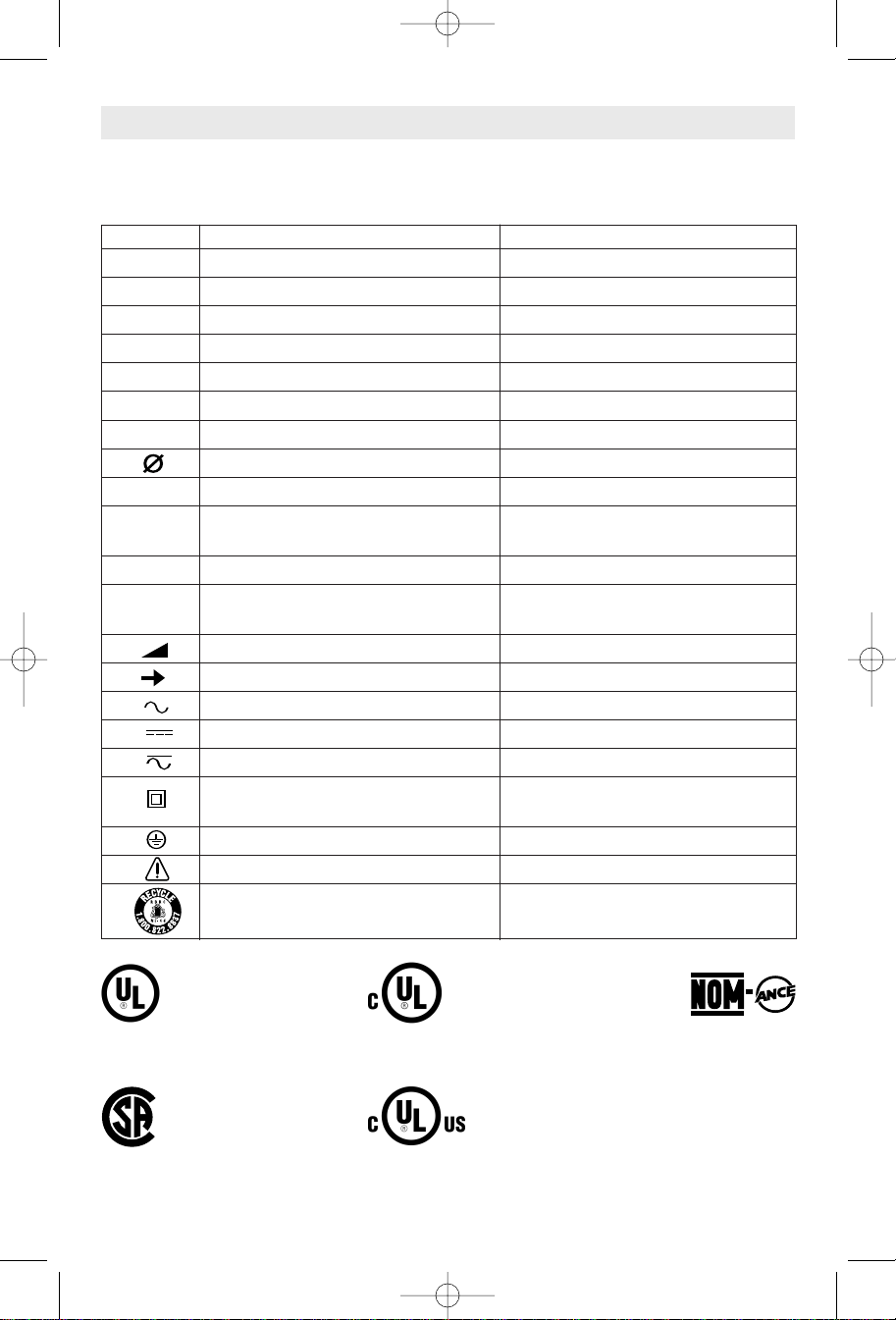
Symbols
MPORTANT:Some of the following symbols may be used on your tool. Please study them
I
and learn their meaning. Proper interpretation of these symbols will allow you to operate the
tool better and safer.
Symbol Name Designation/Explanation
V Volts Voltage (potential)
A Amperes Current
Hz Hertz Frequency (cycles per second)
W Watt Power
kg Kilograms Weight
min Minutes Time
s Seconds Time
Diameter Size of drill bits, grinding wheels, etc.
n
0
.../min Revolutions or reciprocation per minute Revolutions, strokes, surface speed,
0 Off position Zero speed, zero torque...
1, 2, 3, ... Selector settings Speed, torque or position settings.
I, II, III, Higher number means greater speed
No load speed Rotational speed, at no load
orbits etc. per minute
Infinitely variable selector with off Speed is increasing from 0 setting
Arrow Action in the direction of arrow
Alternating current Type or a characteristic of current
Direct current Type or a characteristic of current
Alternating or direct current Type or a characteristic of current
Class II construction Designates Double Insulated
Construction tools.
Earthing terminal Grounding terminal
Warning symbol Alerts user to warning messages
Ni-Cad RBRC seal Designates Ni-Cad battery recycling
program
This symbol designates
that this tool is listed by
Underwriters Laboratories.
This symbol designates
that this tool is listed by
the Canadian Standards
Association.
This symbol designates
that this tool is listed to
Canadian Standards by
Underwriters Laboratories.
This symbol designates that
this tool is listed by
Underwriters Laboratories,
and listed to Canadian
Standards by Underwriters
Laboratories.
This symbol
designates
that
this tool
complies
to NOM
Mexican
Standards.
-5-
BM 1619P00836 12-06 1/5/07 9:42 AM Page 6
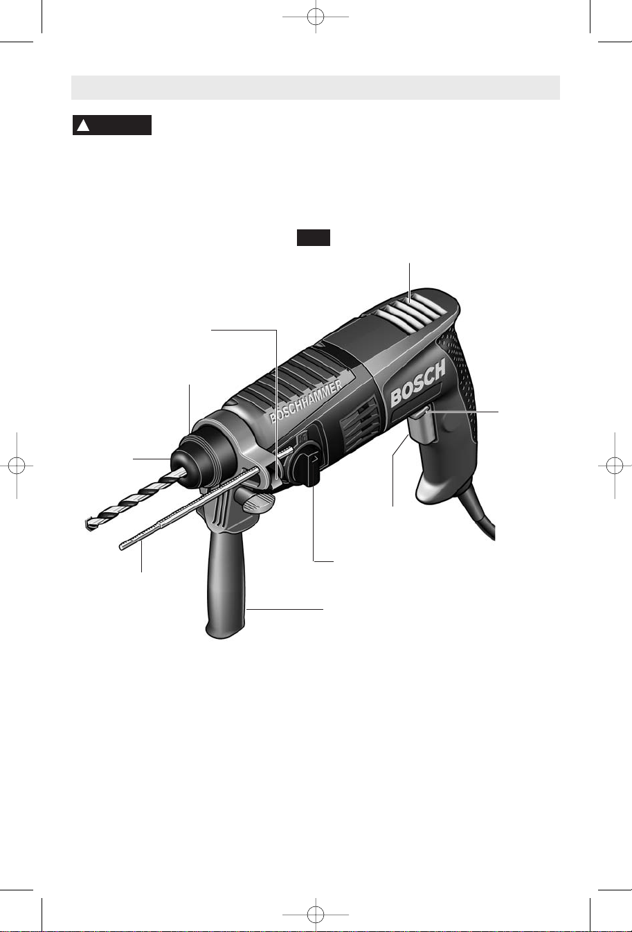
Functional Description and Specifications
WARNING
!
Disconnect the plug from the power source before making any assembly,
adjustments or changing accessories.
reduce the risk of starting the tool accidentally.
Rotary Hammer
DEPTH GAUGE
RELEASE LEVER
LOCKING
SLEEVE
DUST
SHIELD
FIG. 1
Such preventive safety measures
ENTILATION
V
PENINGS
O
VARIABLE SPEED
TRIGGER SWITCH
REVERSING
SWITCH
BUTTON
DRILL/HAMMER DRILL
DEPTH GAUGE
Model number 11258VSR & 11258VSRC
Shank style SDS-Plus
SELECTION DIAL
AUXILIARY HANDLE
®
Maximum Capacities:
Concrete 5/8"
Steel 1/2"
"
Wood
1-1/4
NOTE: For tool specifications refer to the nameplate on your tool.
-6-
BM 1619P00836 12-06 1/5/07 9:43 AM Page 7
Operating Instructions
VARIABLE SPEED CONTROLLED
RIGGER SWITCH
our tool is equipped with a variable speed
Y
rigger switch. The tool speed can be
t
T
controlled from the minimum to the maximum
nameplate RPM by the pressure you apply to
the trigger. Apply more pressure to increase
the speed and release pressure to decrease
speed. This accurate speed control enables
you to drill without center punching. It also
permits you to use as a power screwdriver.
Bits are available for driving screws as well as
running bolts and nuts.
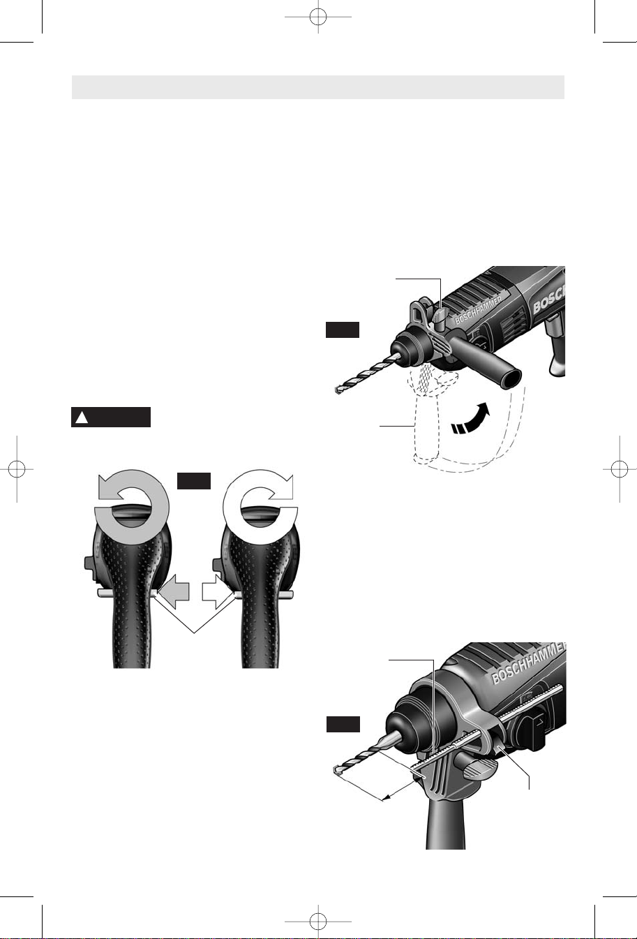
REVERSING SWITCH BUTTON
The reversing switch button is located above
the trigger switch and is used to reverse
rotation of the bit.
For forward rotation, (with the chuck pointed
away from you) move button to the far left. For
reverse rotation move the button to the far
right. (Fig. 2)
CAUTION
!
Do not change direction of
rotation until the tool comes to
a complete stop. Shifting during rotation of the
chuck can cause damage to the tool.
FIG. 2
REVERSING
SWITCH
BUTTON
SLIP CLUTCH
The tool has an internal preset clutch. The
clutch is set such that sufficient force is
transmitted to the bit for most drilling conditions
but it will slip when bit binds in the hole or the
tool is overloaded. Be aware that due to
required clutch setting, you may experience a
torque reaction an instant before the clutch
slips. This torque reaction will twist the body of
the rotary hammer in the opposite direction as
the bit rotates, i.e., counterclockwise. As clutch
is slipping, the bit will most likely stop rotating.
When the binding force on the bit is removed
the clutch automatically resets. If you
xperience bit binding and clutch begins to
e
lip, immediately turn the tool "OFF" and
s
orrect the condition leading to the bit binding.
c
AUXILIARY HANDLE
The auxiliary handle will provide additional
control, support and guidance for the tool. The
handle is adjustable around the 360° handle
collar mount. To mount, loosen wing knob and
slide handle completely over chuck onto the
collar mount and tighten wing knob (Fig. 3).
WING
KNOB
FIG. 3
AUXILIARY
HANDLE
DEPTH GAUGE
Your drilling depth can be pre-set and/or
repeated by using the depth gauge.
Setting depth: After the auxiliary handle is
installed, make sure the accessory has been
fully inserted into the tool holder before setting
the depth gauge (Fig. 4).
To adjust depth, push down on the depth
gauge release lever, slide the depth gauge to
desired depth and release pressure on lever to
lock the depth gauge in place (Fig. 4).
DEPTH
GAUGE
FIG. 4
DEPTH
GAUGE
RELEASE
LEVER
-7-
BM 1619P00836 12-06 1/5/07 9:43 AM Page 8
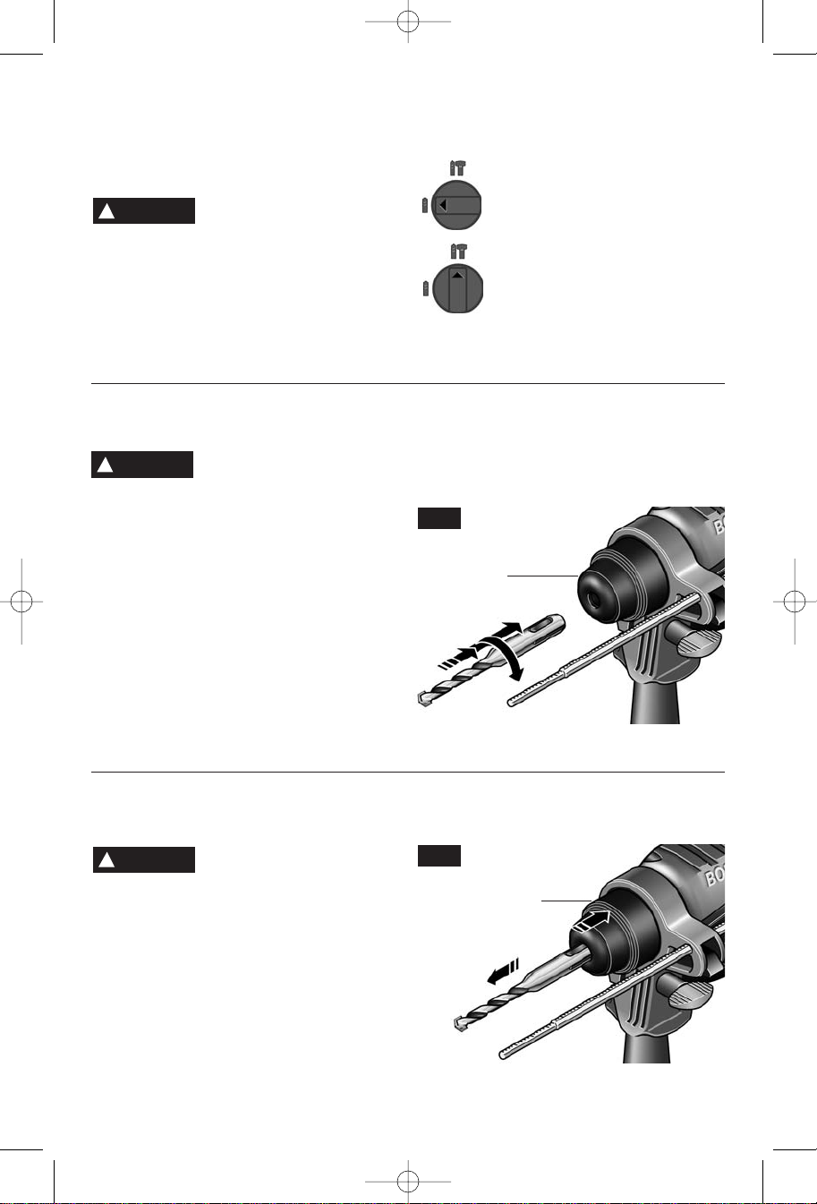
DRILL/HAMMER DRILL SELECTION DIAL
The selector dial allows the tool to be set for
various drilling/hammer drilling applications.
Rotate the selector dial right or left
epending on the below applications (Fig. 1).
d
CAUTION
!
come to a complete stop.
rotation of the chuck can cause damage to
the tool.
WARNING
!
making any assembly, adjustments or
changing accessories.
safety measures reduce the risk of starting the
tool accidentally.
The 11258VSR Rotary Hammer utilizes
“SDS” drill bits. The “SDS” system efficiently
transfers drilling torque and maximizes the
energy delivered per hammer blow.
Clean the insert shank end of the accessory
to remove any debris, then lightly grease with
a light oil or lubricant.
Insert accessory into the tool holder through
the dust shield, while twisting and pushing
Do not operate the
selection dial until the tool
Shifting during
INSTALLING SDS-plus®ACCESSORIES
Disconnect the plug from
the power source before
Such preventive
Do not use demolition or chipping bits such
as bull points, chisels, spades, gouges, etc.
inward until it locks automatically into place.
Pull outward on the accessory to be certain it
is locked into the bit holder (Fig. 5).
FIG. 5
D
w
non concrete materials.
DUST SHIELD
rill only action: For drilling in
oods, metals, plastics or other
Drill with hammer action: For
drilling in concrete, asphalt, tile or
other similar hard materials.
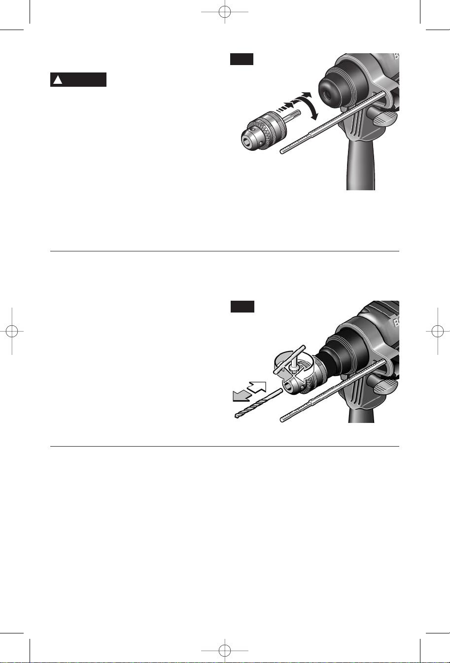
REMOVING SDS-plus®ACCESSORIES
WARNING
!
and use proper protective gloves or cloth to
remove.
To remove an accessory, pull the locking
sleeve backwards (towards the rear of tool),
while pulling the accessory outward (Fig. 6).
All accessories should be wiped clean after
removing.
Accessories may be hot after
use. Avoid contact with skin
-8-
FIG. 6
LOCKING
SLEEVE
BM 1619P00836 12-06 1/5/07 9:43 AM Page 9
INSTALLING & REMOVING 3-JAW CHUCK
!
m
hanging accessories.
c
safety measures reduce the risk of starting the
tool accidentally.
Clean the insert shank end of the chuck to
remove any debris, then lightly grease with a
light oil or lubricant.
Insert chuck into the bit holder through the
dust shield, while twisting and pushing
inward until it locks automatically into place.
Pull outward on the accessory to be certain it
is locked into the tool holder (Fig. 7).
INSTALLING & REMOVING ACCESSORIES
The 3 Jaw Chuck with SDS Shank can convert
your tool for use with straight shank bits.
For small bits, open jaws enough to insert the
bit up to the flutes. For large bits, insert the bit
as far as it will go. Center the bit as you close
the jaws by hand. This positions the bit
properly, giving maximum contact between the
chuck jaws and the bit shank (Fig. 8).
To tighten chuck, insert key into each of the
three key holes in succession and tighten
clockwise firmly.
The chuck can be released by using one hole
only.
(Model 11258VSRC only)
WARNING
aking any assembly, adjustments or
Disconnect the plug from
he power source before
t
uch preventive
S
3-JAW CHUCK
FIG. 7
To remove the chuck, pull the locking sleeve
backwards (towards the rear of tool), while
pulling the chuck outward
Note: The 3-Jaw Chuck is for use only in “Dril
only” mode. The 3-Jaw Chuck is not for use
when drilling with hammering action.
FIG. 8
Following a few simple tips will reduce wear
TOOL TIPS
on the tool and the chance of injury to the
operator.
NOTE: The high efficiency available from the
rotary hammers can only be obtained if sharp
and undamaged accessories are used. The
“cost” to maintain sharp and undamaged
accessories is more than offset by the “time
saved” in operating the tool with sharp
accessories.
All hammers require a short period of time to
warm up. Depending on the room
temperature, this time may vary from
approximately 15 seconds (90˚F) to 2 minutes
(32˚F). A new hammer requires a break-in
period before full performance is realized. This
period may require up to 5 hours of operation.
Carbide tipped bits: Used for drilling stone,
concrete, cement, brick, cinder block and
other unusually hard non-metals. The Rotary
Hammer is designed for “SDS” Carbide
Tipped Bits up to 3/4 inch diameter.
-9-

BM 1619P00836 12-06 1/5/07 9:43 AM Page 10
You will extend the life of your bits and do
neater work if you always put the bit in contact
with the workpiece BEFORE pulling the
rigger. During operation, hold the drill firmly
t
nd exert moderate, steady pressure. Too
a
uch pressure at low speed will stall the
m
hammer. Too little pressure will keep the bit
from cutting and cause excess friction by
sliding over the surface. This can be
damaging to the drill and bit.
Shanks of all drill bits should be wiped clean
prior to using and immediately after removing.
Recall these instructions for safe
operation:
1. Some materials require slow drilling
speeds; whereas, others require higher speed
to produce the best results.
2. All work must be supported or secured
before drilling and steady, even pressure
applied in line with the drill bit.
3. As the drill bit cuts through the opposite
side, reduce the pressure and continue
running the drill as the bit is withdrawn.
Materials such as glass, porcelain, ceramics,
tiles, plastics, etc., should be drilled at low
speeds with specially designed drill bits and
lubricants.
DRILLING WOOD OR PLASTIC
If backing block is not used, ease up on the
pressure just before the bit breaks through
he wood to avoid splintering. Complete the
t
ole from the opposite side immediately after
h
he point breaks through. If bit binds, reverse
t
the drilling operation to help remove the bit
from the work.
Make a center punch in the material for
easier starting. Use enough pressure to keep
the bit cutting. If the bit is allowed to merely
spin in the hole, it will become dull within a
short time. When drilling a larger hole, it is
faster and easier on your power pack to first
make a smaller hole and enlarge it to the
required size. Lubricate the tip of the bit
occasionally with CUTTING OIL for easier
metal drilling. If bit binds, reverse the drilling
to help remove the bit from the work.
Use carbide-tipped masonry bit for cinder
block, mortar, common brick, soft stone and
other materials. The amount of pressure to
be used is dependent upon the type of
material being drilled. Soft materials require
less pressure while the hard materials need
more pressure to prevent the drill bit from
spinning.
DRILLING METAL
DRILLING MASONRY
Maintenance
Service
WARNING
!
orized personnel may result in misplacing
of internal wires and components which
could cause serious hazard.
recommend that all tool service be performed
by a Bosch Factory Service Center or Authorized Bosch Service Station.
Your Bosch tool has been properly lubricated
and is ready to use. It is recommended that
tools with gears be regreased with a special
gear lubricant at every brush change.
Preventive maintenance
performed by unauth-
We
TOOL LUBRICATION
The brushes and commutator in your tool
CARBON BRUSHES
have been engineered for many hours of
dependable service. To maintain peak
efficiency of the motor, we recommend every
two to six months the brushes be examined.
Only genuine Bosch replacement brushes
specially designed for your tool should be
used.
BEARINGS
After about 300-400 hours of operation, or at
every second brush change, the bearings
should be replaced at Bosch Factory Service
Center or Authorized Bosch Service Station.
Bearings which become noisy (due to heavy
load or very abrasive material cutting) should
be replaced at once to avoid overheating or
motor failure.
-10-
 Loading...