

Bosch 11253VSR, GBH2-26 Operating/safety Instructions Manual
11253VSR
GBH2-26
11255VSR
RH226
Operating/Safety Instructions
Consignes d’utilisation/de sécurité
Instrucciones de funcionamiento y seguridad
For English Version
See page 2
Version française
Voir page 14
Versión en español
Ver la página 26
IMPORTANT
Read Before Using
IMPORTANT
Lire avant usage
IMPORTANTE
Leer antes de usar
Call Toll Free for Consumer Information & Service Locations
Pour obtenir des informations et les adresses de nos centres de service après-vente, appelez ce numéro gratuit
Llame gratis para obtener información para el consumidor y ubicaciones de servicio
1-877-BOSCH99 (1-877-267-2499) www.boschtools.com
2610047983_11253VSR 10/2/17 1:10 PM Page 1
-2-
Work area safety
Keep work area clean and well lit. Cluttered
or dark areas invite accidents.
Do not operate power tools in explosive
atmospheres, such as in the presence of
flammable liquids, gases or dust. Power
tools create sparks which may ignite the dust
or fumes.
Keep children and bystanders away while
operating a power tool. Distractions can
cause you to lose control.
Electrical safety
Power tool plugs must match the outlet.
Never modify the plug in any way. Do not
use any adapter plu g s with earth e d
(grounded) power tools. Unmodified plugs
an d matching outlets w i l l reduce r i s k of
electric shock.
Avoid body contact with earthed or grounded
surfaces such as pipes, radiators, ranges
and refrigerators. There is an increased risk
of electric shock if your body is earthed or
grounded.
Do not expose power tools to rain or wet
conditions. Water entering a power tool will
increase the risk of electric shock.
Do not abuse the cord. Never use the cord
for carrying, pulling or unplugging the power
tool. Keep cord away from heat, oil, sharp
edges or moving parts. Damaged or entangled
cords increase the risk of electric shock.
When operating a power tool outdoors,
use an extension cord suitable for outdoor
use. Use of a cord suitable for outdoor use
reduces the risk of electric shock.
If operating a power tool in a damp location
is unavoidable, use a Ground Fault Circuit
Interrupter (GFCI) protected supply. Use of
an GFCI reduces the risk of electric shock.
Personal safety
Stay alert, watch what you are doing and
us e co m mon sense when operating a
power tool. Do not use a power tool while
you are tired or under the influence of drugs,
alcohol or medication. A moment of inattention
while operating power tools may result in
serious personal injury.
Use personal protective equipment. Always
Read all safety warnings and all instructions. Failure to follow the warnings
and instructions may result in electric shock, fire and/or serious injury.
SAVE ALL WARNINGS AND INSTRUCTIONS FOR FUTURE REFERENCE
The term “power tool” in the warnings refers to your mains-operated (corded) power tool or
battery-operated (cordless) power tool.
!
WARNING
General Power Tool Safety Warnings
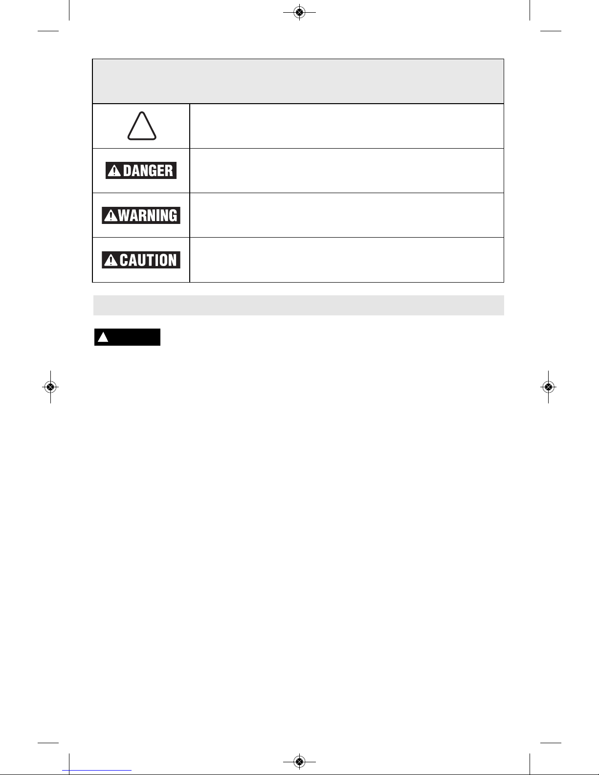
Safety Symbols
The definitions below describe the level of severity for each signal word. Please read the manual
and pay attention to these symbols.
!
This is the safety alert symbol. It is used to alert you to potential
personal injury hazards. Obey all safety messages that follow this
symbol to avoid possible injury or death.
DANGER indicates a hazardous situation which, if not avoided, will
result in death or serious injury.
WARNING indicates a hazardous situation which, if not avoided, could
result in death or serious injury.
CAUTION, used with the safety alert symbol, indicates a hazardous
situation which, if not avoided, will result in minor or moderate injury.
2610047983_11253VSR 10/2/17 1:10 PM Page 2

-3-
Wear ear protectors. Exposure to noise can
cause hearing loss.
Use auxiliary handle(s), if supplied with the
tool. Loss of control can cause personal injury.
Hold power tools by insulated gripping
surfaces, when performing an operation
where the cutting tool may contact hidden
wiring or its own cord. Cutting accessory
contacting a "live" wire may make exposed
metal parts of the power tool "live" and could
give the operator an electric shock.
Do not drill, fasten or break into existing
walls or other blind areas where electrical
wiri ng may exis t . If th is situ at i on is
unavoidable, disconnect all fuses or circuit
breakers feeding this worksite.
Use a metal detector to determine if there
are gas or water pipes hidden in the work
area or call the local utility company for
assi st a nc e befo re begi nn i ng the
operation. Striking or cutting into a gas line
will result in explosion. Water entering an
electrical device may cause electrocution.
w
ear eye protection. Protective equipment
such as dust mask, non-skid safety shoes, hard
hat, or hearing protection used for appropriate
conditions will reduce personal injuries.
Prevent unintentional starting. Ensure the
sw itch is in the off -position before
connecting to power source and / or battery
pa ck, picking u p or carrying the t ool.
Carrying power tools with your finger on the
switch or energizing power tools that have the
switch on invites accidents.
Remove any adjusting key or wrench before
turning the power tool on. A wrench or a
key left attached to a rotating part of the power
tool may result in personal injury.
Do not overreach. Keep proper footing and
balance at all times. This enables better
control of the power tool in unexpected
situations.
Dress properly. Do not wear loose clothing
or jewelry. Keep your hair, clothing and
gloves away from moving parts. Loose
clothes, jewelry or long hair can be caught in
moving parts.
If devices are provided for the connection
of dust extraction and collection facilities,
ensure these are connected and properly
used. Use of dust collection can reduce dust-
related hazards.
Power tool use and care
Do not force th e power to o l . Use the
correct power tool for your application. The
correct power tool will do the job better and
safer at the rate for which it was designed.
Do not use the power tool if the switch does
not turn it on and off. Any power tool that
c
annot be contro l l ed with the switch is
dangerous and must be repaired.
Disconnect the plug from the power source
and/or the battery pack from the power tool
before making any adjustments, changing
accessories, or storing power tools. Such
preventive safety measures reduce the risk of
starting the power tool accidentally.
Store idle power tools out of the reach of
children and do not allow persons unfamiliar
with the power tool or these instructions to
operate the power tool. Power tools are
dangerous in the hands of untrained users.
Maintain power tools. Check for misalignment
or binding of moving parts, breakage of
parts and any other condition that may
affect the power tool’s operation. If damaged,
have the power tool repaired before use.
Many ac c i dents are ca u s ed b y p o o rly
maintained power tools.
Keep cutting tools sharp and clean. Properly
maintained cutting tools with sharp cutting
edges are less likely to bind and are easier to
control.
Use the power tool, accessories and tool
bits etc. in accordance with these instructions,
taking into account the working conditions
and the work to be performed. Use of the
power tool for operations different from those
intended could result in a hazardous situation.
Service
Have your power tool serviced by a qualified
repair person using only id e ntical
replacement parts. This will ensure that the
safety of the power tool is maintained.
Specific Safety Rules for Rotary Hammers
2610047983_11253VSR 10/2/17 1:10 PM Page 3

A
lways use the side handle for maximum
control over torque reaction or kick-back.
Never attempt to operate this tool with
one hand. The slip clutch engages if you
firmly control the tool during a torque reaction
or kickback.
Alwa ys w ea r sa f et y go g gl es o r ey e
protection when using this tool. Use a
dust mask or respirator for applications
that generate dust. Safety goggles or eye
protection will help deflect fragments of the
material that may be thrown toward your face
and eyes. Dust generated or gases released
from th e ma t er ia l yo u ar e cut ti n g (i .e.
asbestos insulated pipes, radon) may cause
respiratory difficulties.
Use thick cushioned gloves and limit the
exposure time by taking frequent rest
periods. Vibration caused by hammer-drill
action may be harmful to your hands and
arms.
Position the cord clear of rotating bit. Do
not wrap the cord around your arm or
wrist. If cord becomes entangled with the
sp inning bit it could entrap you causing
serious personal injury.
Position yourself to avoid being caught
between the tool or side handle and walls
or posts. Should the bit become bound or
jammed in the work, the reaction torque of
the tool could crush your hand or leg.
If t he bit beco m es bo un d in t h e
work pi e ce , rele as e the trig ge r
immediately, reverse the directio n of
rotation and slowly squeeze the trigger to
back out the bit. Be ready for a strong
reaction torque. The tool body will tend to
twist in the opposite direction as the bit is
rotating. (Note: use only if tool has reversing
feature.)
Do not st r ike the bit with a ha n d held
hamm er or sled ge h am m er when
atte mp t in g to d i sl od g e a bo un d or
jammed bit. Fragments of metal from the bit
could dislodge and strike you or bystanders.
Never place the tool down until the bit or
accessory has come to a complete stop.
Do not use dull or damag e d bits an d
accessories. Dull or damaged bits have a
greater tendency to bind in the workpiece.
When removing the bit from the tool avoid
cont ac t with skin and us e prop er
protective gloves when grasping the bit or
accessory. Accessories may be hot after
prolonged use.
D
o not run the tool while carrying it at
your side. A spinning bit could become
entangled with clothing and injury may result.
If devices are provided for the connection to
dust collection and extraction systems, be
su re these ar e connected a nd used
according to tool and vacuum instructions.
Proper use of dust collection can reduce dust
related hazards.
If devices are provided for the connection of
dust collection and extraction systems,
empty the dust container before beginning
wo rk, f r equently during work, after
completion of work, and before storing the
tool. Be extremely careful of dust disposal,
ma terials in fine part icles form may be
explosive.
Do not throw dust on an open fi re.
Co mbustion from mixtur e of var nishes,
lacquers, polyurethane, oil or water with dust
particles can occur if there is a static discharge,
electric spark, or excessive heat.
Do not use dust extraction for operations
where dust may include burning, smoking
or smoldering items like hot ashes or
sparks. Fire inside the vacuum tank or bag
may occur. Dust may smolder and set vacuum
on fire long after work is completed.
Do not use dust extraction with explosive
dusts, varnish, polyurethane coatings,
cleaners, or oil-based paints. Electric motors
create sparks which may ignite the dust or
fumes.
Do not use dust extraction when working on
metal. Swarf from drilling metal may be hot and
may spark which may melt plastic adaptors,
vacuum hoses and may cause a fire inside the
vacuum tank or bag.
Do not dril l int o met al wi th th e du st
extraction system mounted. Hot metal chips
can self-ignite or ignite parts of the dust
extraction system.
Do not drill into wood with dust extraction
system mounted. Wood chips are typically too
large and will clog the dust channel.
Your tool is equipped with a dust canister,
empty it frequently, after completion of
drilling and before storing the tool. Be
extremely careful of dust disposal, materials
in fine particle form may be explosive.
Note: Do not use the dust extraction system
when chiselling, screwdriving or cutting threads.
-4-
2610047983_11253VSR 10/2/17 1:10 PM Page 4

GFCI and personal protection devices like
electrician’s rubber gloves and footwear will
further enhance your personal safety.
Do not use AC only rated tools with a DC
power supply. While the tool may appear to
work, the electrical components of the AC
rated tool are likely to fail and create a hazard
to the operator.
Keep handles dry, clean and free from oil
and grease. Slippery hands cannot safely
control the power tool.
Develop a periodic maintenance schedule
for your tool. When cleaning a tool be
careful not to disassemble any portion of
th e tool since interna l wire s may be
misplaced or pinched or safety guard return
sp rings may be improp erly mount e d.
Certain cleaning agents such as gasoline,
carbon tetrachloride, ammonia, etc. may
damage plastic parts.
Risk of injury to user. The power cord must only
be serviced by a Bosch Factory Service Center
or Autho rized Bosch Service Station.
Some dust created by power
sanding, sawing, grinding,
drilling, and other construction activities
contains chemicals known to cause cancer,
birth defects or other reproductive harm.
Some examples of these chemicals are:
• Lead from lead-based paints,
• Crystalline silica from bricks and cement and
other masonry products, and
• Arsenic and chromium from chemically-
treated lumber.
Your risk fr om these exposures varies ,
depending on how often you do this type of
work. To reduce your exposure to these
chemicals: work in a well ventilated area, and
work with approved safety equipment, such as
those dust masks that are specially designed
to filter out microscopic particles.
-5-
Additional Safety Warnings
!
WARNING
2610047983_11253VSR 10/2/17 1:10 PM Page 5
-6-
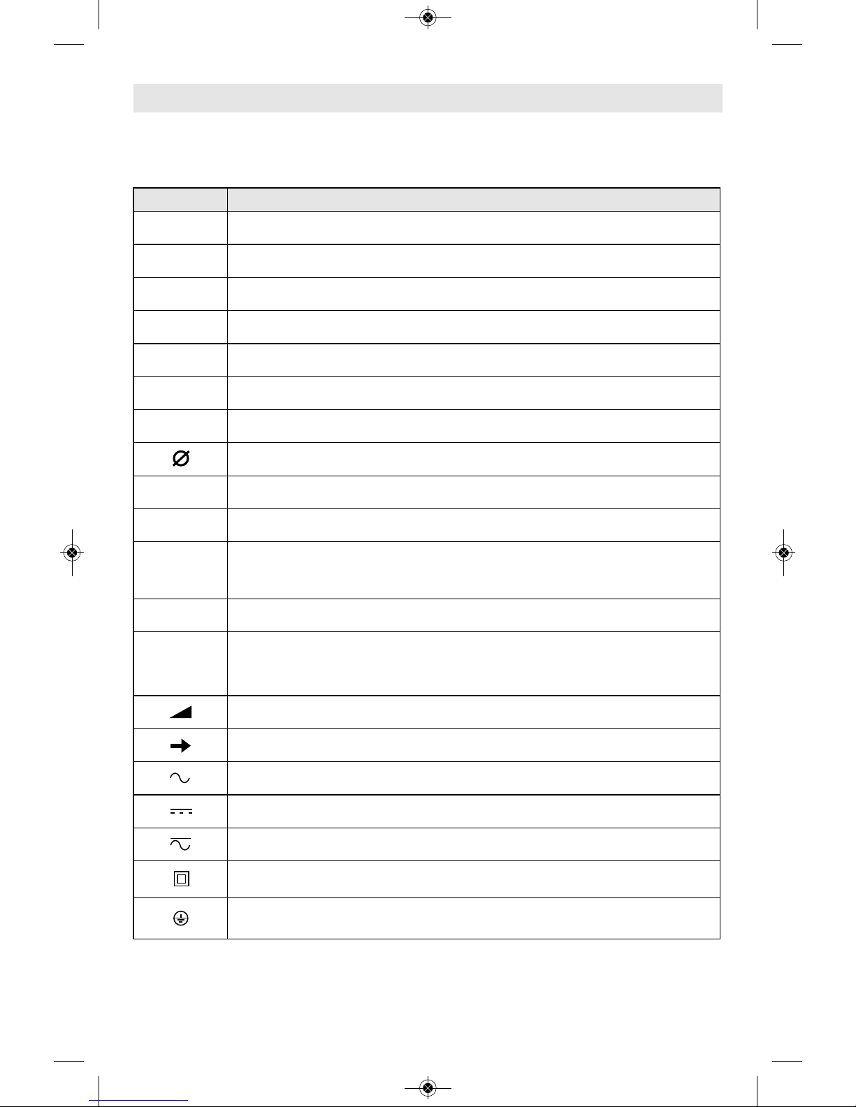
Symbols
IMPORTANT: Some of the following symbols may be used on your tool. Please study them
and learn their meaning. Proper interpretation of these symbols will allow you to operate the
tool better and safer.
Symbol Designation / Explanation
V Volts (voltage)
A Amperes (current)
Hz Hertz (frequency, cycles per second)
W Watt (power)
kg Kilograms (weight)
min Minutes (time)
s Seconds (time)
Diameter (size of drill bits, grinding wheels, etc.)
n
0
No load speed (rotational speed at no load)
n Rated speed (maximum attainable speed)
.../min
Revolutions or reciprocation per minute (revolutions, strokes, surface speed,
orbits etc. per minute)
0 Off position (zero speed, zero torque...)
1, 2, 3, ...
I, II, III,
Selector settings (speed, torque or position settings. Higher number means
greater speed)
0
Infinitely variable selector with off (speed is increasing from 0 setting)
Arrow (action in the direction of arrow)
Alternating current (type or a characteristic of current)
Direct current (type or a characteristic of current)
Alternating or direct current (type or a characteristic of current)
Class II construction (designates double insulated construction tools)
Earthing terminal (grounding terminal)
2610047983_11253VSR 10/2/17 1:10 PM Page 6
-7-
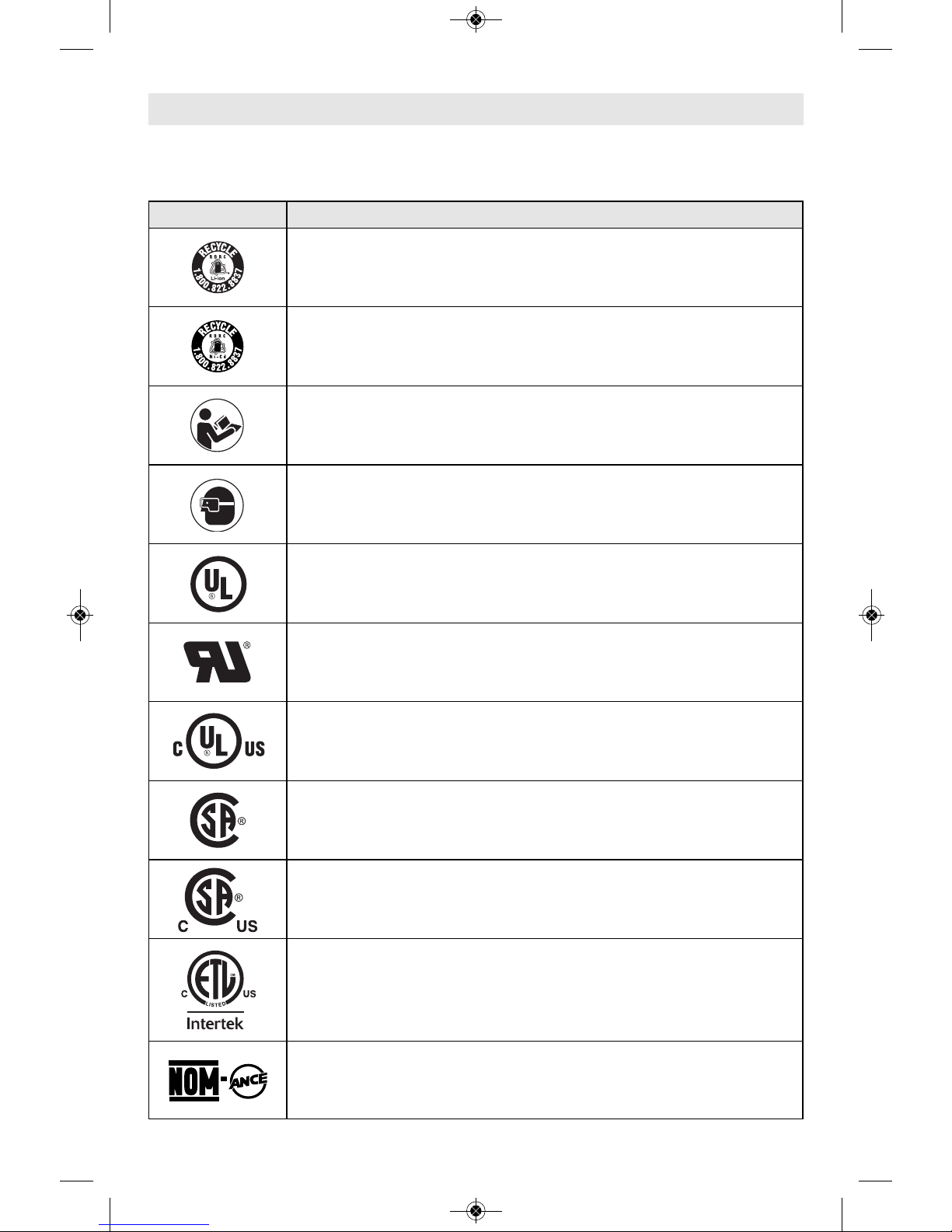
Symbols (continued)
IMPORTANT: Some of the following symbols may be used on your tool. Please study them
and learn their meaning. Proper interpretation of these symbols will allow you to operate the
tool better and safer.
Symbol Designation / Explanation
Designates Li-ion battery recycling program
Designates Ni-Cad battery recycling program
Alerts user to read manual
Alerts user to wear eye protection
This symbol designates that this tool is listed by Underwriters Laboratories.
This symbol designates that this component is recognized by Underwriters
Laboratories.
This symbol designates that this tool is listed by Underwriters Laboratories,
to United States and Canadian Standards.
This symbol designates that this tool is listed by the Canadian Standards
Association.
This symbol designates that this tool is listed by the Canadian Standards
Association, to United States and Canadian Standards.
This symbol designates that this tool is listed by the Intertek Testing
Services, to United States and Canadian Standards.
This symbol designates that this tool complies to NOM Mexican Standards.
2610047983_11253VSR 10/2/17 1:10 PM Page 7
-8-
Functional Description and Specifications
Disconnect the plug from the power source before making any assembly,
adjustments or changing accessories. Such preventive safety measures
reduce the risk of starting the tool accidentally.
!
WARNING
Rotary Hammer
Model number 11253VSR & GBH2-26 11255VSR & RH226
Shank style SDS-plus
®
SDS-plus
®
Maximum Capacities:
Carbide tipped bits 1" 1"
Thin wall core bits 2-5/8" 2-5/8"
NOTE: For tool specifications refer to the nameplate on your tool.
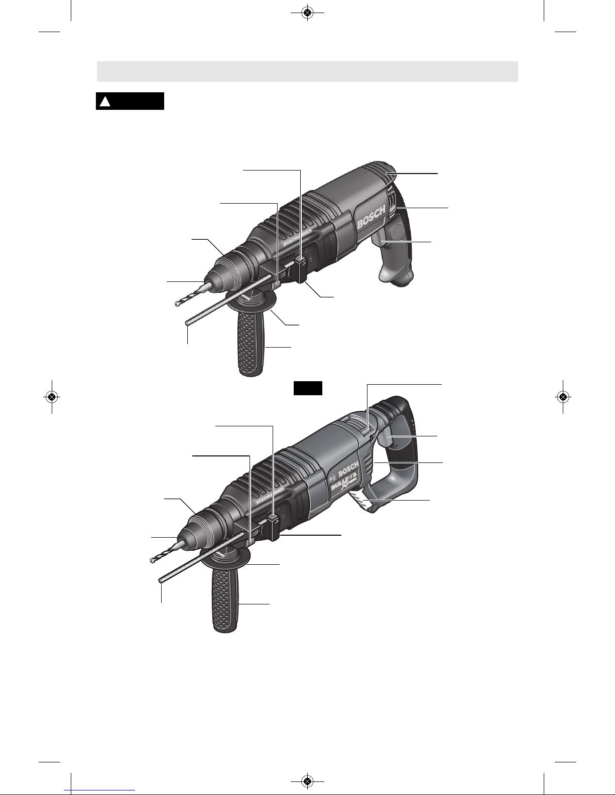
DUST SHIELD
VENTILATION
OPENINGS
REVERSING
SWITCH
LEVER
VARIABLE SPEED
TRIGGER SWITCH
LOCKING SLEEVE
DEPTH GAUGE
RELEASE BUTTON
RELEASE BUTTON
SELECTOR DIAL
HAND GRIP
AUXILIARY HANDLE
FIG. 1
SELECTOR DIAL
DEPTH
GAUGE
HAMMERHOOK
™
(Models 11255VSR &
RH226 only)
REVERSING
SWITCH
LEVER
VARIABLE SPEED
TRIGGER SWITCH
VENTILATION
OPENINGS
RELEASE BUTTON
SELECTOR DIAL
DEPTH GAUGE
RELEASE BUTTON
LOCKING
SLEEVE
DUST SHIELD
DEPTH
GAUGE
SELECTOR DIAL
AUXILIARY HANDLE
HAND GRIP
2610047983_11253VSR 10/2/17 1:10 PM Page 8
Disconnect the plug from
the power source before
making any assembly, adjustments or
changing accessories. Such preventive
safety measures reduce the risk of starting the
tool accidentally.
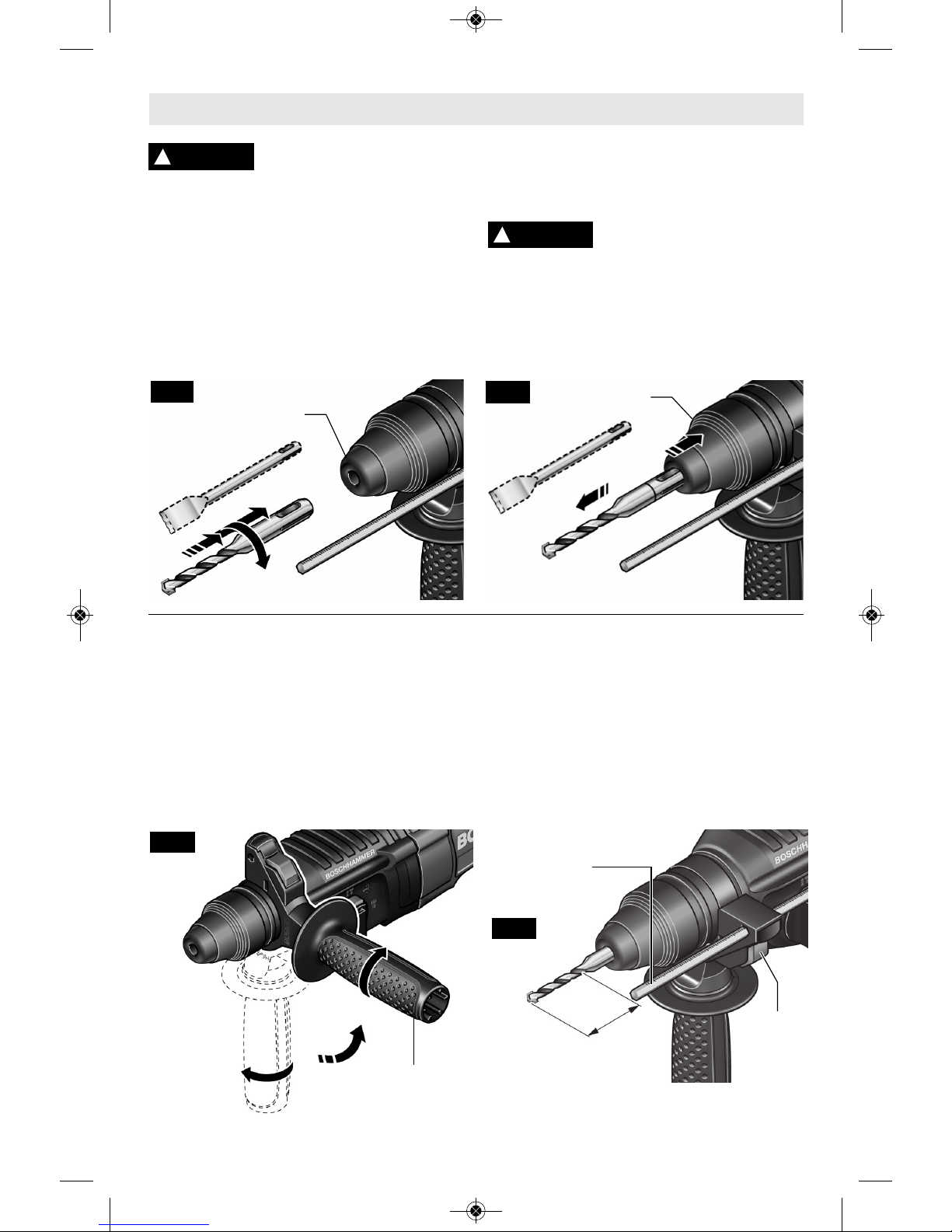
INSTALLING SDS-plus
®
ACCESSORIES
Clean the insert shank end of the accessory to
remove any debris, then lightly grease with a
light oil or lubricant.
Insert accessory into the chuck through the
dust shield, while twisting and pushing inward
until it locks automatically into place. Pull
outward on the accessory to be certain it is
locked into the chuck (Fig. 2).
REMOVING SDS-plus
®
ACCESSORIES
Accessories may be hot after
use. Avoid contact with skin
and use proper protective gloves or cloth to
remove.
To remove an accessory, pull locking sleeve
backward and pull bit forward. All accessories
should be wiped clean after removing (Fig. 3).
-9-
AUXILIARY HANDLE
The tool must be supported with the auxiliary
handle, which can be swiveled 360˚. To
reposition and/or swivel the handle, loosen
the hand g ri p , mo v e the han d le to th e
desi re d po s it i on alo ng t he b a rr el a nd
securely retighten the hand grip (Fig. 4).
DEPTH GAUGE
Your drilling depth can be pre-set and/or
repeated by using the depth gauge.
Setting depth: After the auxiliary handle is
installed, make sure the accessory has been
fully inserted into the tool holder before
setting the depth gauge (Fig. 5).
To adju s t de p th, push th e depth gauge
release button, slide the depth gauge to
desired depth and release pressu r e on
button to lock the depth gauge in place.
Assembly
!
WARNING
DUST
SHIELD
FIG. 2
!
WARNING
LOCKING
SLEEVE
FIG. 3
HAND GRIP
FIG. 4
DEPTH
GAUGE
RELEASE
BUTTON
DEPTH
GAUGE
FIG. 5
2610047983_11253VSR 10/2/17 1:10 PM Page 9
-10-
Operating Instructions
VARIABLE SPEED CONTROLLED
TRIGGER SWITCH
Your tool is equipped with a variable speed
trig ge r swit c h. The to ol spee d can be
controlled from the minimum to the maximum
nameplate speed by the pressure you apply
to th e tr i gg e r. A pp ly mor e pr es s ur e to
increase the speed and release pressure to
decrease speed. This accurate speed control
enables you to drill without center punching.
It als o pe rm i ts yo u to us e as a po w er
screwdriver. Bits are available for driving
screws as well as running bolts and nuts.
REVERSING SWITCH LEVER
This tool is equipped with a rotating brush
reversing system. This results in longer brush
life while maximizing power in both forward and
re verse directions. The reverse switch can be
oper ated from either the right or left side of the
tool.
FOR FORWARD ROTATION: slide switch to
arrow marked forward (Fig. 1).
FOR REVERSE RO TATION: slide the slide
switch to arrow marked re verse. NOTE: Tool
will not operate in middle position.
SLIP CLUTCH
The tool has an internal preset clutch. The
clutch is set such that sufficient force is
tran sm i tt e d to the bi t for mo s t drill in g
conditions but it will slip when bit binds in the
hole or the tool is overloaded. Be aware that
du e to required clutch setting, you may
ex p e r i ence a torque reaction an instant
before the clutch slips. This torque reaction
will twist the body of the rotary hammer in the
opposite direction as the bit rotates, i.e.,
counterclockwise. As clutch is slipping, the
bit will most likely stop rotating. When the
binding force on the bit is removed the clutch
automatically resets. If you experience bit
binding and clutch begins to slip, immediately
turn the tool "OFF" and correct the condition
leading to the bit binding.
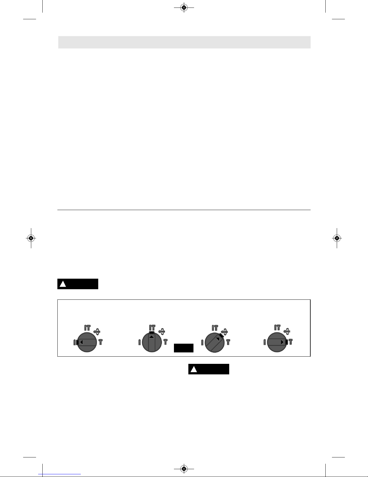
SELECTOR DIAL
The selector dial allows the tool to be set for
various drilling/hammer drilling applications.
Depress release button and turn selector dial
right or left depending on the below applications.
When using demolition or chipping bits such as
bull points, chisels, spades, gouges, etc. the
“Hammer Only” mode must be selected.
Do not operate the selection dial until the
tool come to a complete
stop. Shifting during rotation of
the chuck can cause damage to the tool.
SELECTOR DIAL - “VARIO-LOCK”
Adjusting the Vario-Lock: The vario-lock
can be set in any on e of th i r ty- s i x (10˚
increments) positions. Choose a position
which is best suited for your operation.
Depress release button and turn the selector
dial, to the “vario-lock” setting. Next, rotate
the locking sleeve, along with the accessory,
to the desired position. Then turn the selector
dial to the “hammer only” setting and slightly
turn the l o ck in g sl e ev e to h a ve it
automatically lock into a definite position.
!
CAUTION
Drilling only: Drilling/hammering: Vario-lock Hammering only:
used for drilling used for drilling allows for 36 desired used for light
wood, steel, etc. concrete positions of “hammer” chipping work
FIG. 6
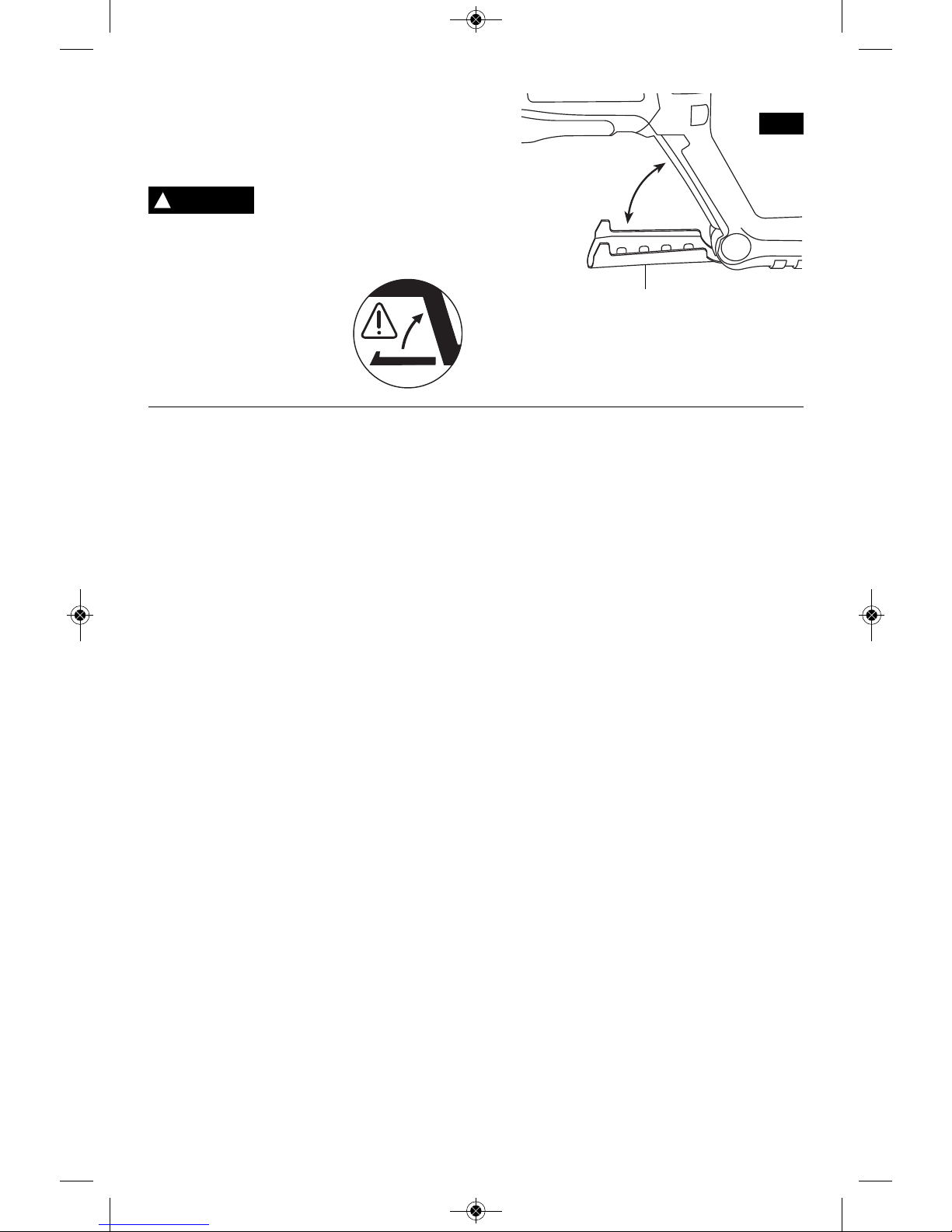
HAMMERHOOK
™
(Model 11255VSR & RH226 only)
Your tool is equipped with a convenient hook
for hanging your tool. To use, simply open hook
until it snaps into the open position (Fig. 7).
When using the HAMMERHOOK™ always
be aware that the accessory is exposed.
Always hang the tool in an area wher e
yourself and bystandards can not accidently
make contact with the accessory.
To r e du c e t he r is k o f
inju ry , use c ar e in
selecting the location for hanging the
tool.
• Select a suitably sized and shaped object
that will provide adequate hanging stability.
An unstable hanging surface could result in
the tool unexpectedly falling.
• Insure that the tool is hung out of the way of
!
WARNING
2610047983_11253VSR 10/2/17 1:10 PM Page 10
TOOL TIPS
Following a few simple tips will reduce wear on
the tool and the chance of injury to the
operator.
NOTE: The high efficiency available from the
rotary hammers can only be obtained if sharp
and undamaged accessories are used. The
“cost” to maintain sharp and undamaged
accessories is more than offset by the “time
saved” in operating the tool with sharp
accessories.
All hammers require a short period of time to
warm up. Depending on the room temperature,
this time may vary from approximately 15
seconds (90˚F) to 2 minutes (32˚F).
A new hammer requires a break-in period
before full performance is realized. This period
may require up to 5 hours of operation.
You will extend the life of your bits and do
neater work if you always put the bit in contact
with the workpiece BEFORE pulling the trigger.
During operation, hold the drill firmly and exert
moderate, steady p r e s s u r e . Too much
pressure at low speed will stall the hammer.
Too little pressure will keep the bit from cutting
and cause excess friction by sliding over the
surface. This can be damaging to the drill and
bit.
Carbide tipped bits: Used for drilling stone,
concrete, cement, brick, cinder block and other
unusually hard non-metals.
3-JAW CHUCK
(Drill only mode)
The 3-Jaw Chuck with SDS-plus
®
Shank
Adaptor accessory can convert your tool for
use with straight shank bits.
Shanks of all drill bits should be wiped clean
prior to using and immediately after removing.
Recall these instructions for safe
operation:
1. All work must be supported or secured
before drilling and steady, even pressure
applied in line with the drill bit.
2. As the drill bit cuts through the opposite
side, reduce th e pressure and continue
running the drill as the bit is withdrawn.
3. So m e materials require slow drilling
speeds; whereas, others require higher speed
to produce the best results. Materials such as
glass, porcelain, ceramics, tiles, plastics, etc.,
should be drilled at low speeds with specially
designed drill bits and lubricants.
DRILLING WOOD OR PLASTIC
(Drill only mode)
If backing block is not used, ease up on the
pressure just before the bit breaks through the
wood to avoid splintering. Complete the hole
from the opposite side immediately after the
point breaks through. If bit binds, reverse the
drilling operation to help remove the bit from
the work.
DRILLING METAL
(Drill only mode)
There are two rules for drilling hard materials.
First, the harder the material, the greater the
pres sure yo u need to apply to the to o l .
Second, the harder the material, the slower the
speed. Here are a couple of tips for drilling in
metal. Make a center punch in the material for
easier starting. Lubri cate the tip of the bit
occasionally with cutting oil except when
drilling soft metals such as alu minum, cop per
or cast iron. If the hole to be drilled is fairly
large, drill a smaller hole first, then enlarge to
the required size, it’s often faster in the long
run. Main tain enough pressure to assure that
w
alkw ay s and w or k in g area s wit h
bystanders. The tool could be bumped or a
bystander could become entangled in the
powe r sup p ly co r d ca u si ng th e to ol to
unexpectedly fall.
To r e du c e t he r i sk of
inju ry , Do not us e the
hanging hook if it appears damaged or
deformed. This could result in unstable
hanging and the tool unexpectedly falling.
When not in use, always
close hook until it snaps
into the closed position.
-11-
!
WARNING
H
AMMERHOOK
™
FIG. 7
To Open
T
o Close
2610047983_11253VSR 10/2/17 1:10 PM Page 11

t
he bit does not just spin in the hole. This will
dull the bit and greatly shorten its life.
D
RILLING MASONRY
Use carbide-tipped masonry bit for cinder
block, mortar, common brick, soft stone and
o
ther materials. The amount of pressure to be
used is dependent upon the type of material
being drilled. Soft materials require less
pressure while the hard materials need more
pressure to prevent the drill bit from spinning.
-12-
Dust Extraction
For selection of dust collection systems and
operating instructions, see the Operating /
Safet y I n st r uct i on s f or ‘ D us t E x tr a c ti o n
Attachments for Hammers and Hammer Drills’
inclu d ed wi t h your to o l or with the du s t
extraction attachment.
Service
Preventive mai ntenance
perf or m ed by un a ut h orized per so n nel may result in misplacing
of internal wires and components which
coul d caus e seri ou s h az ar d . We
recommend that all tool service be performed
by a Bosch Factory Service Center or Autho rized Bosch Service Station.
TOOL LUBRICATION
Your Bosch tool has been properly lubricated
and is ready to use. It is recommended that
tools with gears be regreased with a special
gear lubricant at every brush change.
CARBON BRUSHES
The brushes and commutator in your tool have
been engineered for many hours of dependable
service. To maintain peak efficiency of the
motor, we recommend every two to six months
the brush es be examined. Only genuine Bosch
replace ment brushes specially designed for
your tool should be used.
BEARINGS
After about 300-400 hours of operation, or at
every second brush change, the bearings
should be replaced at Bosch Factory Service
Center or Au thorized Bosch Service Station.
Bearings which become noisy (due to heavy
load or very abrasive material cut ting) should
be replaced at once to avoid overheating or
motor failure.
Cleaning
To avoid accidents always
dis connect the tool from
the power suppl y be f ore clea n ing or
performing any main tenance. The tool may
be cleaned most effectively with compressed
dry air. Always wear safety gog gles when
cleaning tools with compressed air.
Ventilation openings and switch levers must
be kept clean and free of foreign matter. Do
not at tempt to clean by inserting pointed
objects through openings.
Ce r t ain cle a n i ng agen t s
and so l vent s dam a ge
plastic parts. Some of these are: gasoline,
carbon tetrachlo ride, chlo rinated cleaning
solv en t s, a m mo n ia and ho u se ho ld
detergents that contain ammonia.
!
WARNING
!
WARNING
Maintenance
!
CAUTION
2610047983_11253VSR 10/2/17 1:10 PM Page 12
 Loading...