

Page 1

WARNING:
Improper installation, setup, modifi cation, operation or
maintenance of the heating system can cause personal
injury and property damage.
Follow each appliances' instructions precisely.
For assistance or further information, contact a trained
and certifi ed installer, service provider, or the gas
supply company.
In Massachusetts, the boiler must be installed by a
licensed plumber or gas fi tter.
Application drawings in this manual are conceptual only
and do not purport to address all design, installation,
code, or safety considerations.
The diagrams in this manual are for reference use by
code offi cials, designers and licensed installers. It is
expected that installers have adequate knowledge of
national and local codes, as well as accepted industry
practices, and are trained on equipment, procedures,
and applications involved. Drawings are not to scale.
Refer to the boiler, control and module installer manuals
for additional detailed information!
Gas Condensing Boiler
Bosch
100, 151 Combi Boiler
57, 100, 131, 151 Heating Boiler
Applications Manual
Page 2

|
2
Bosch Greenstar Applications Manual
Bosch Thermotechnology Corp.Data subject to change
Page 3

Applications Manual Bosch Greenstar | 3
Table of Contents
1 Information about the appliance 4
1.1 Boiler types and sizes 4
1.2 FW200 Boiler Energy Management 5
1.3 FB100 Remote Control & Room Sensor 6
1.4 IPM2 Space Heating Module 7
1.5 ISM2 Solar Module 8
2 Applications 9
Legend 9
List of most common applications 10
Boiler pump capacity in single zone systems 11
Single Zone Baseboard Systems:
2.1 System 1: Greenstar Heating Boiler in a
single zone system 13
2.2 System 2: Greenstar Combi Boiler in a
single zone system 17
2.3 System 3: Greenstar Heating Boiler in a single
zone system with DHW tank loading 21
2.4 System 4: Greenstar Heating Boiler in a single
zone system with solar thermal DHW and
boiler backup 25
Single Zone Systems with Primary/Secondary Piping:
2.5 System 5: Greenstar Heating Boiler in a
single zone system 29
2.6 System 6: Greenstar Combi Boiler in a
single zone system 33
2.7 System 7: Greenstar Heating Boiler in a single
zone system with DHW tank loading 37
2.8 System 8: Greenstar Heating Boiler in a single
zone system with room thermostat and DHW
tank loading 41
2.9 System 9: Greenstar Heating Boiler in a single
zone system with solar thermal DHW and
boiler backup 45
Multi-zone Systems with Primary/Secondary Piping:
2.10 System 10: Greenstar Heating Boiler with
zone pumps and room thermostats 49
2.11 System 11: Greenstar Heating Boiler with
zone pumps, room thermostats and DHW
tank loading 53
2.12 System 12: Greenstar Heating Boiler with
zone valves and room thermostats 57
Bosch Thermotechnology Corp.
Data subject to change
Page 4

|
4
Bosch Greenstar Applications Manual
1 Information about the appliance
1.1 Boiler types and sizes
Greenstar Heating boilers
Greenstar 57: ZBR 16-3, 54,600btu (16kW) output
Greenstar 100: ZBR 28-3, 95,500btu (28kW) output
Greenstar 131: ZBR 35-3, 119,400btu (35kW) output
Greenstar 151: ZBR 42-3, 143,000btu (42kW) output
Greenstar Combi-boilers
Greenstar Combi 100: ZWB 28-3, 95,500btu (28kW)
output
Greenstar Combi 151: ZWB 42-3, 143,000btu (42kW)
output
Bosch Thermotechnology Corp.Data subject to change
Page 5

Applications Manual Bosch Greenstar | 5
1.2 FW200 Boiler Energy Management
System
The Boiler Energy Management System includes the
FW200 user programming interface with integrated
outdoor reset control.
In connection with the IPM2 module the FW200 offers
an outdoor reset control for two heating zones and
DHW generation with time programs:
— Central heating
programs with six programmable switch points
per day (one program is active).
— DHW
points per day.
— DHW Recirculation pump program.
Options:
— Remote control and room sensor FB100
provides status information and a programming
interface in each zone.
— Module ISM2 for solar DHW heating and solar
space heating support.
Programs and settings are stored in a permanent
memory and remain even during power outages.
: weekly DHW program with six switch
: Six weekly heating
Scope of delivery
2
5
2x
2x
Fig. 1 FW200 Energy Management System
1 Controls top section
2 Base for wall-mounting
3 Top cover
4 Installation and operating instructions
5 Outdoor temperature sensor with mounting kit
3
8
1
4
Installation options:
— In the boiler
— Wall-mounted as a remote room sensor
Bosch Thermotechnology Corp.
Data subject to change
Page 6

|
6
Bosch Greenstar Applications Manual
1.3 FB100 Remote Control & Room Sensor
The FB100 can only be connected
to systems with FW200 and a boiler
with BUS-enabled Heatronic 3.
The FB100 is a remote room sensor and user interface
that is used to display device and system information
and to change the settings of that particular zone.
The FB100 is designed for wall mounting.
In connection with the IPM2 module, the FB100
controls the assigned heating circuit using a timer
program. Three weekly heating programs with six
switch points per day are available for a heating circuit
(one program is active).
Maximum of four FB100 in a heating system with
FW200.
In case of power failure, the display will be off. All
settings are saved.
Scope of delivery
2
1
4
Fig. 2 FB100 Remote Control & Room Sensor
1 Upper part of remote control
2 Base for wall-mounting
3 Top cover
3
8
4 Installation and operating instructions
Bosch Thermotechnology Corp.Data subject to change
Page 7

Applications Manual Bosch Greenstar | 7
1.4 IPM2 Space Heating Module
The IPM2 module operates pumps and mixing valves of
2 heating zones. Each zone is run independently based
on the programming and feedback from the FB100 room
sensor (if installed). Instead of a second zone a DHW
recirculation pump can also be controlled by the IMP-2.
Combination overview
Outdoor reset controls
and primary room sensor
Remote control for
additional zones
Available
systems
Max. number of Modules
per system
Tab. 1
FW200
FB100
2 mixed heating zones
1 mixed heating zone
+ 1 unmixed heating zone
+ 1 DHW recirculation pump
2 unmixed heating zones
+ 1 DHW recirculation pump
1 mixed heating zone
+ 1 storage tank
+ 1 DHW tank loading pump
1 unmixed heating zone
+ 1 storage tank
+ 1 DHW tank loading pump
max. 5 IPM2
Bosch Thermotechnology Corp.
Data subject to change
Page 8

|
8
Bosch Greenstar Applications Manual
1.5 ISM2 Solar Module
The ISM2 module controls the components of a solar
thermal system. Integration of solar thermal with a boiler
and central heating system for backup brings additional
benefi ts as it allows minimizing boiler run time and
reduces burner starts signifi cantly compared to a non-
integrated system.
Combination overview
With the ISM2 module, it is possible to realize a variety of
solar thermal systems.
Basic solar thermal systems
System 1 : Solar thermal DHW heating
System 2 : Solar thermal DHW heating and space
heating support
System expansions
Option A : Two collector arrays (east/west orientation)
Option B : Reloading system with two single coil DHW
tanks
Option C : First/second priority system with 2 tanks,
realized with
— p-p : a separate pump for each tank
— p-v : common pump and diverter valve
Option D : External heat exchanger on the solar circuit
Option E : Thermal disinfection of the solar tank
Combine a basic system with one or several options to
realize the desired solar system.
This manual shows basic solar thermal DHW systems only.
For information on all options, please consult the Installation and Service Manual.
Bosch Thermotechnology Corp.Data subject to change
Page 9
Applications Manual Bosch Greenstar | 9
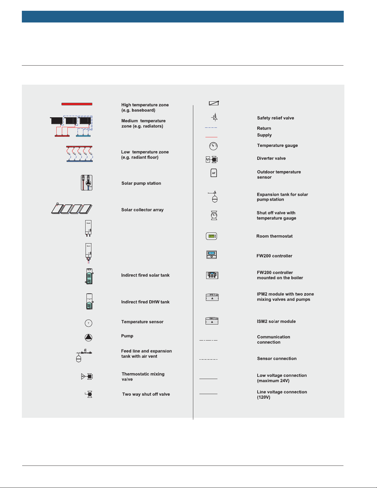
2 Applications
Legend
Flow check valve
pipe
pipe
Greenstar
Greenstar
Greenstar boiler
Greenstar combi-boiler
Fig. 3 Legend
NOTICE: All drawings in this manual are conceptual in nature and only depict components relevant for the systems
shown. It is the installer's responsibility to know national and local code and install safety devices as required. Install
and size peripheral devices such as air purge, expansion vessel, feeder valve, mud separator, shutoff valves, etc. per best
installation practices. Contact Bosch with installation related questions.
Bosch Thermotechnology Corp.
Data subject to change
Page 10

|
10
Bosch Greenstar Applications Manual
List of most common applications
Single Zone Baseboard Systems:
System 1: Greenstar Heating Boiler in a single zone
system (page 13-16).
System 2: Greenstar Combi-Boiler in a single zone
system (page 17-20).
System 3: Greenstar Heating Boiler in a single zone
system with DHW tank loading ( page 21-24).
System 4: Greenstar Heating Boiler in a single zone
system with solar thermal DHW and boiler backup
(page 25-28).
Single Zone Systems with Primary/Secondary Piping:
System 5: Greenstar Heating Boiler in a single zone
system (page 29-32)
System 6: Greenstar Combi-Boiler in a single zone
system (page 33-36).
System 7: Greenstar Heating Boiler in a single zone
system with DHW tank loading (page 37-40)
System 8: Greenstar Heating Boiler in a single zone
system with room thermostat and DHW tank loading
(page 41-44).
System 9: Greenstar Heating Boiler in a single zone
system with solar thermal DHW and boiler backup
(page 45-48).
Multi-zone Systems with Primary/Secondary Piping:
System 10: Greenstar Heating Boiler with zone pumps
and room thermostats (page 49-52).
System 11: Greenstar Heating Boiler with zone pumps,
room thermostats, and DHW tank loading (page 53-
56).
System 12: Greenstar Heating Boiler with zone valves
and room thermostats ( page 57-60).
Bosch Thermotechnology Corp.Data subject to change
Page 11

Applications Manual Bosch Greenstar | 11
Boiler pump capacity in single zone systems
When installing the boiler in a single zone application
without primary/secondary piping, it is critical not to
overload the pump. Use the Greenstar Heating or Combi
Boiler in this setup only in low pressure baseboard
applications. Radiant fl oor, panel radiator, or multi-zone
applications require primary/secondary piping. Do not
install zone valves with this system.
Recommended maximum: 70' (21 m) of 3/4" baseboard
at a 20°F delta T and a fl ow rate of 4.0 gpm. This allows
suffi cient reserves for the necessary supply and return
piping plus elbows.
Alternatively determine the system pressure drop on a case
by case basis to verify that the boiler pump is capable of
delivering the required fl ow rate. Table 2 provides as an
example the pressure drop of 100’ of 3/4” baseboard and
its relevant heat output.
Water Flow Pressure Drop per 100' MBH output per 100’ at shown Medium Water Temperature
GPM feet of head 110°F 120°F 130°F 140°F 150°F 160°F 170°F 180°F
4 4.375 16 12 26 32 38 46 54 61
Tab. 2 Pressure drop and heat output for ¾” baseboard
and 65°F Room Temperature
Add to that the pressure drop of supply and return piping
plus elbows and other devices like check valves.
Use the pump curves on the following page to verify that
the pump is capable of delivering the needed fl ow rate for
the given pressure drop of the system.
In order to save as much energy as possible and
keep water circulation noises to a minimum, select
the lowest possible pump speed.
If the working pressure cannot be met, use primary/
secondary piping.
Bosch Thermotechnology Corp.
Data subject to change
Page 12
|
12
Bosch Greenstar Applications Manual
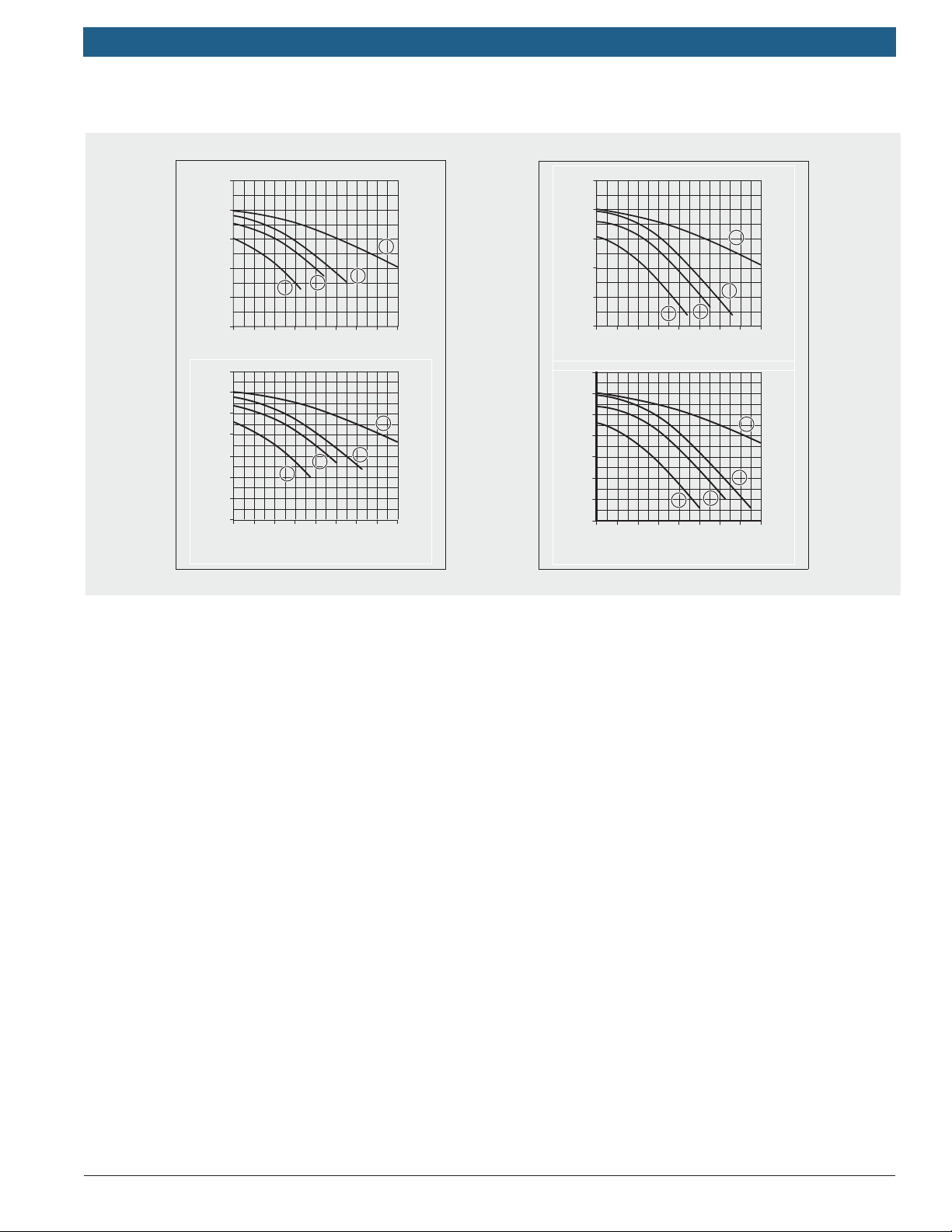
Pump curve of heating boiler Pump curve of combi boiler (heating side)
25
20
15
H / ft
10
5
0
02 5781436
7
6
5
4
3
H / m
2
1
0
0
2
1
.
V / gpm
2
1
400 800 1200 1600200 600 1000 1400
.
V / l/h
4
3
4
3
6 720 641 933-59.1O
Fig. 4 Greenstar boiler pump curves
Key to Fig. 4
1 Residual head pressure at speed 1
2 Residual head pressure at speed 2
3 Residual head pressure at speed 3 (default setting)
25
20
15
H / ft
10
5
0
0213546 87
7
6
5
4
3
H / m
2
1
0
0
1
.
V / gpm
1
400 800 1200 1600
.
V / l/h
4
3
2
4
3
2
6 720 641 933-61.1O
4 Head pressure of the boiler pump by itself (at speed 3)
H Head pressure in feet of head (m)
V Circulating water volume in gallons per minute (l/h)
Bosch Thermotechnology Corp.Data subject to change
Page 13

Applications Manual Bosch Greenstar | 13
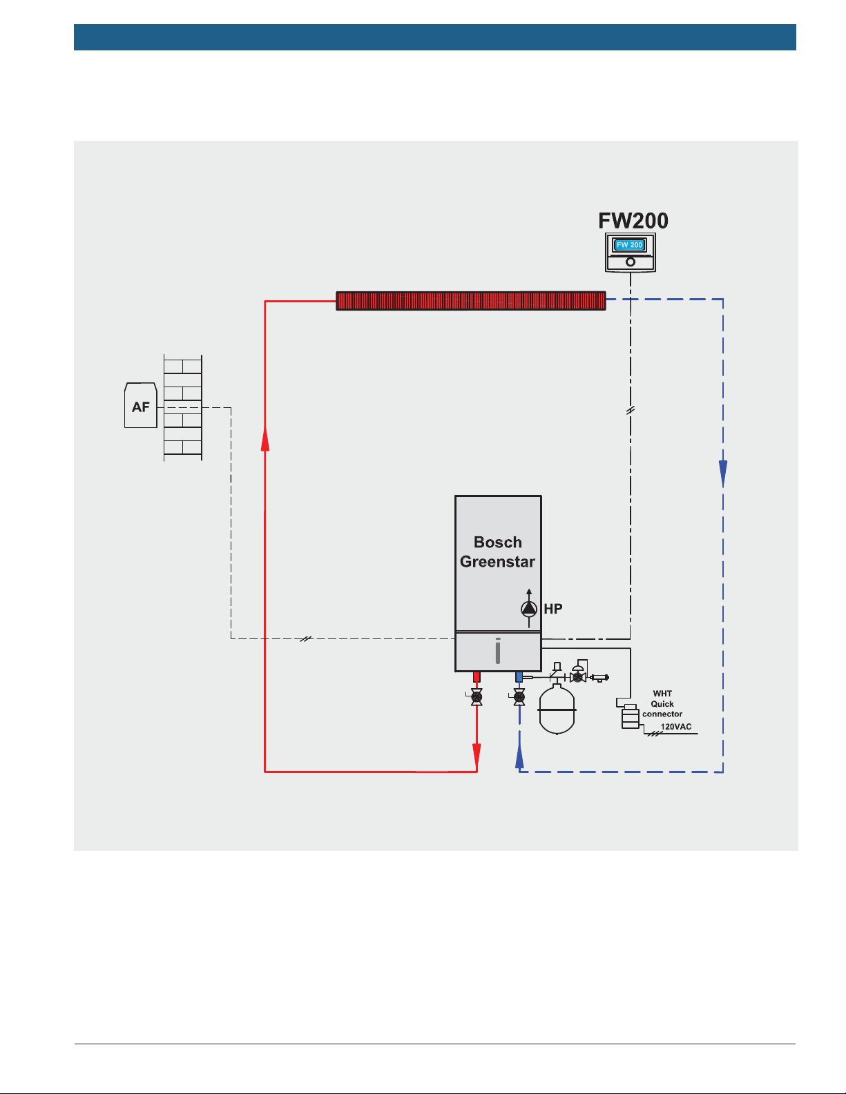
2.1 System 1: Greenstar Heating Boiler in a
single zone system
Summary:
Single boiler supplying one baseboard heating zone
equipped with FW200 outdoor reset controller with built-in
room sensor in the living space. This system is using the
boiler pump for zone water circulation.
This design can only be used with a single loop baseboard
system that has a low pressure drop. Radiant fl oors, panel
radiator, or multi zone systems require primary-secondary
piping. Do not install zone valves with this system.
The pump will run in constant circulation except when in
warm weather shutdown.
Max. 70' (21 m) of 3/4" baseboard at a 20°F delta T and a
fl ow rate of 4.0 gpm plus the necessary supply and return
piping.
In detail:
The FW200 is an outdoor temperature based controller
with room temperature infl uence. The controller adjusts
the heating curve (boiler supply temperature) according to
outdoor temperature. When the FW200 is wall mounted,
it also uses room temperature to adjust the heating curve
and modify boiler supply temperature.
FW200 provides warm weather shutdown.
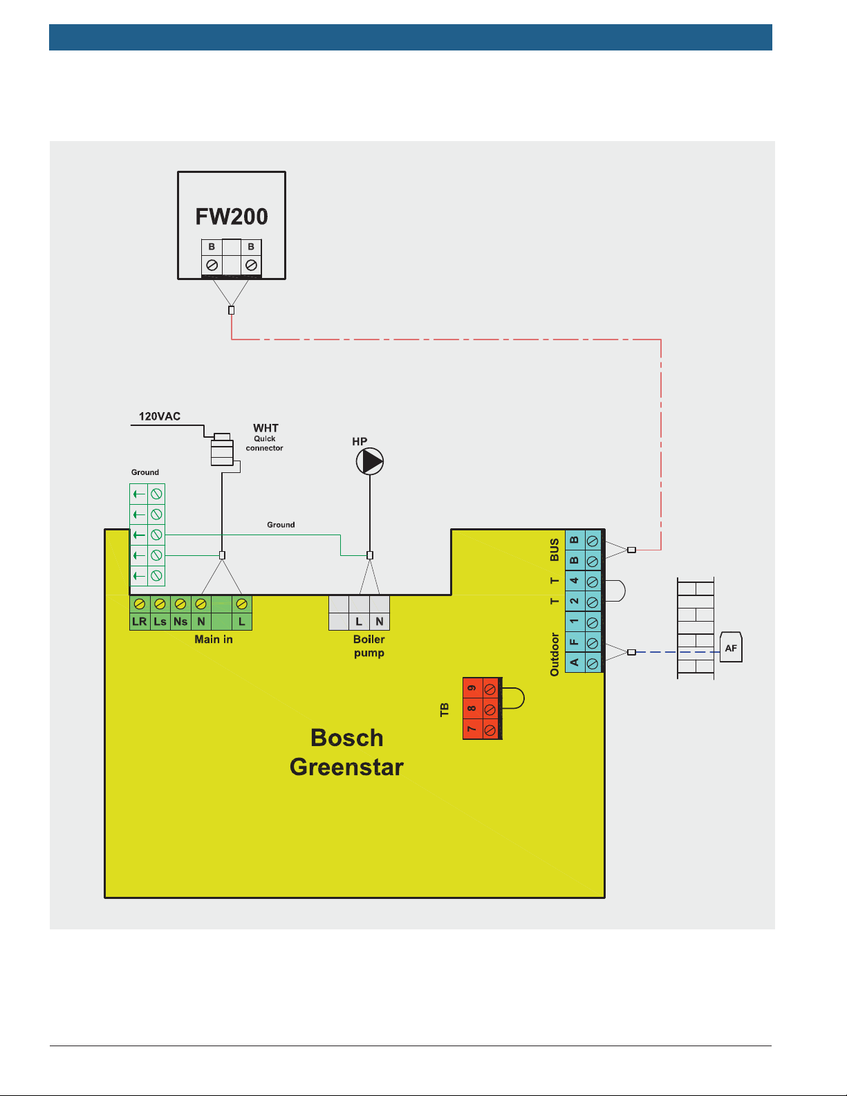
Required components:
Greenstar heating boiler.
FW200 controller in the room.
Additional instructions:
See manufacturer’s installation and operating instructions.
Bosch Thermotechnology Corp.
Data subject to change
Page 14
|
14
Bosch Greenstar Applications Manual
System 1 - Piping Diagram
Bosch Thermotechnology Corp.Data subject to change
Page 15
Applications Manual Bosch Greenstar | 15
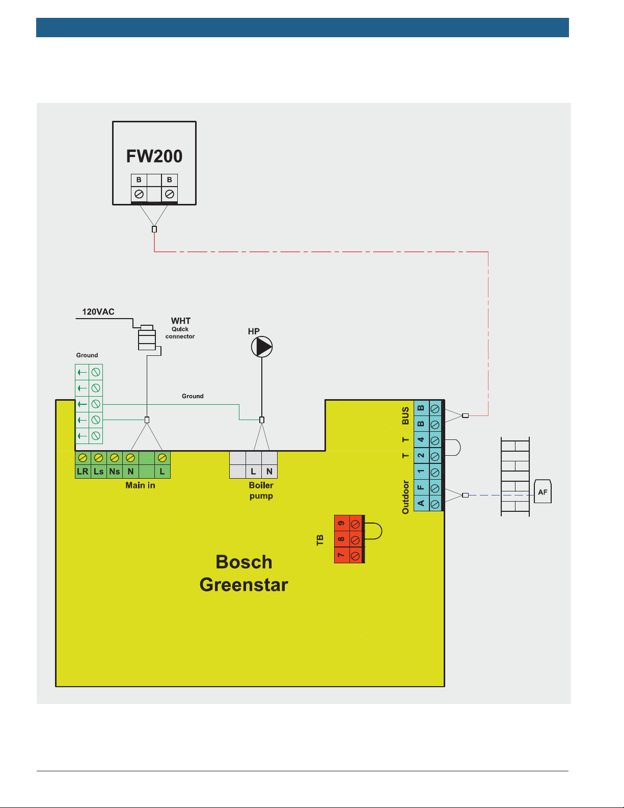
System 1 - Wiring Diagram
Bosch Thermotechnology Corp.
Data subject to change
Page 16

|
16
Bosch Greenstar Applications Manual
System 1: Setup and Programming
In this single zone system the FW200 is installed in the
living space in a location that represents the conditions
of the entire zone. Avoid locations exposed to direct or
indirect sunlight, heat sources, draft, etc. that can lead to
over compensation.
Initial setup:
See the installation instructions for description of buttons
and displays, and for details on setup and programming.
Power up the boiler.
When commissioning for the first time set the display
language, date and time.
Upon first commissioning the automatic system
configuration starts. Wait 60 seconds and follow the
instructions displayed. You have the option of using
the factory settings or entering custom parameters to
better match the individual requirements.
Set up the weekly heating program for the three
available temperature levels:
— Comfort
When done, ensure the mode selector is set to AUTO.
The room temperature will be displayed.
Additional information:
With outdoor reset the boiler will provide the water temperature according to the heating curve adjusted by the
level of room infl uence (if enabled).
The boiler will always attempt to run at its highest
efficiency in low fire for as long as necessary.
The boiler will shut down when the target temperature
is reached followed by a 3 minute post purge by the
pump.
— The boiler and the pump will start again when
the supply water temperature drops 18°F (10°C)
below the set point.
— Economy
— Frost (Frost protection)
Take advantage of using one of the preset programs
from the list or enter a custom program.
— Program A
— Program F
— AM weekday worker
— PM weekday worker
— All day
— All day, lunch
— Family
— All day, early shift
— All day, late shift
— Seniors
Set the room temperatures for the three specified
temperature levels.
Enter the installer menu to configure the heating zone.
— Set heating circuit type to Baseboard.
— Set the minimum outdoor temperature, building
storage capacity, design day temperature, and
maximum supply temperature.
— Set the room influence followed by the
remaining parameters as they apply to the
system.
Bosch Thermotechnology Corp.Data subject to change
Page 17

Applications Manual Bosch Greenstar | 17
2.2 System 2: Greenstar Combi Boiler in a
single zone system
Summary:
Single combi-boiler supplying one baseboard heating
zone equipped with FW200 outdoor reset controller with
built-in room sensor in the living space. DHW generation
directly off the boiler through the tankless heat exchanger.
This system is using the boiler pump for zone water circulation.
The “combi” or combination boiler is a high effi ciency
central heating boiler and water heater combined within
one compact unit. Water is heated on demand directly
from the water main eliminating the need for a hot water
storage tank.
This design can only be used with a single loop baseboard
system that has a low pressure drop. Radiant fl oors, panel
radiator, or multi zone systems require primary-secondary
piping. Do not install zone valves with this system.
The pump will run in constant circulation while in space
heating mode except during a call for DHW or when in
warm weather shutdown.
Max. 70' (21 m) of 3/4" baseboard at a 20°F delta T and a
fl ow rate of 4.0 gpm plus the necessary supply and return
piping..
Additional instructions:
See manufacturer’s installation and operating instructions.
Install an adequately sized Pressure Relief Valve (PRV) on
the DHW outlet of the combi boiler.
To reduce the risk of scalding it is recommended to install
a DHW tempering valve.
The Greenstar combi boiler is equipped with an internal 3.17 gal (12 liter) expansion vessel. The installation
manual provides information on how to determine if it is
of suffi cient capacity for the application or if an additional
expansion vessel is needed.
In detail:
The FW200 is an outdoor temperature based controller
with room temperature infl uence. The controller adjusts
the heating curve (boiler supply temperature) according to
outdoor temperature. When the FW200 is wall mounted,
it also uses room temperature to adjust the heating curve
and modify boiler supply temperature.
FW200 provides warm weather shutdown.
Required components:
Greenstar combi-boiler.
FW200 controller in the room.
Bosch Thermotechnology Corp.
Data subject to change
Page 18

|
18
Bosch Greenstar Applications Manual
System 2 - Piping diagram
Bosch Thermotechnology Corp.Data subject to change
Page 19
Applications Manual Bosch Greenstar | 19
System 2 - Wiring diagram
Bosch Thermotechnology Corp.
Data subject to change
Page 20

|
20
Bosch Greenstar Applications Manual
System 2: Setup and Programming
In this single zone system the FW200 is installed in the
living space in a location that represents the conditions
of the entire zone. Avoid locations exposed to direct or
indirect sunlight, heat sources, draft, etc. that can lead to
over compensation.
DHW is generated directly by the combi-boiler without the
need for a storage tank.
Initial setup:
See the installation instructions for description of buttons
and displays, and for details on setup and programming.
Power up the boiler.
When commissioning for the first time set the display
language, date and time.
Upon first commissioning the automatic system
configuration starts. Wait 60 seconds and follow the
instructions displayed. You have the option of using
the factory settings or entering custom parameters to
better match the individual requirements.
Enter the installer menu to configure the heating zone.
— Set heating circuit type to Baseboard.
— Set the minimum outdoor temperature, building
storage capacity, design day temperature, and
maximum supply temperature.
— Set the room influence followed by the
remaining parameters as applicable.
Set up the weekly program for DHW generation.
For additional features of the combi boiler see the
installation manual.
When done, ensure the mode selector is set to AUTO.
The room temperature will be displayed.
Additional information
With outdoor reset the boiler will provide the water temperature according to the heating curve adjusted by the
level of room infl uence (if enabled).
The boiler will always attempt to run at its highest
efficiency in low fire for as long as necessary.
Set up the weekly heating program for the three avail-
able temperature levels:
— Comfort
— Economy
— Frost (Frost protection)
Take advantage of using one of the preset programs
from the list or enter a custom program.
— Program A
— Program F
— AM weekday worker
— PM weekday worker
— All day
— All day, lunch
— Family
— All day, early shift
— All day, late shift
— Seniors
Set the room temperatures for the three specified
temperature levels.
The boiler will shut down when the target temperature
is reached followed by a 3 minute post purge by the
pump.
The boiler and the pump will start again when the
supply water temperature drops 18°F (10°C) below
the set point.
When the demand for hot water is sensed by the flow
sensor, the boiler will change to DHW mode. When the
DHW demand ends, the boiler will return to heating
mode.
Bosch Thermotechnology Corp.Data subject to change
Page 21

Applications Manual Bosch Greenstar | 21
2.3 System 3: Greenstar Heating Boiler in a
single zone system with DHW tank loading
Summary:
Single boiler supplying one baseboard heating zone
equipped with FW200 outdoor reset controller with builtin room sensor in the living space. This system is using the
boiler pump for zone water circulation and DHW tank loading. A diverter valve is used to switch between space heating and tank loading. This system is identical to System 1
with an added indirect fi red DHW tank.
This design can only be used with a single loop baseboard
system that has a low pressure drop. Radiant fl oors, panel
radiator, or multi zone systems require primary-secondary
piping.
Max. 70' (21 m) of 3/4" baseboard at a 20°F delta T and a
fl ow rate of 4.0 gpm plus the necessary supply and return
piping.
Ensure to select a DHW tank with a coil pressure drop that
does not exceed the capacity of the boiler pump.
In detail:
The FW200 is an outdoor temperature based controller
with room temperature infl uence. The controller adjusts
the heating curve (boiler supply temperature) according to
outdoor temperature. When the FW200 is wall mounted,
it also uses room temperature to adjust the heating curve
and modify boiler supply temperature.
FW200 provides warm weather shutdown.
Required components:
Greenstar combi-boiler.
FW200 controller in the room.
Indirect Fired DHW Tank.
Diverter valve 120VAC, 3-way, spring return.
Additional instructions:
See manufacturer’s installation and operating instructions.
Bosch Thermotechnology Corp.
Data subject to change
Page 22

|
22
Bosch Greenstar Applications Manual
System 3 - Piping diagram
Bosch Thermotechnology Corp.Data subject to change
Page 23

Applications Manual Bosch Greenstar | 23
System 3 - Wiring diagram
Bosch Thermotechnology Corp.
Data subject to change
Page 24

|
24
Bosch Greenstar Applications Manual
System 3: Setup and Programming
In this single zone system the FW200 is installed in the
living space in a location that represents the conditions
of the entire zone. Avoid locations exposed to direct or
indirect sunlight, heat sources, draft, etc. that can lead to
over compensation.
Initial setup:
See the installation instructions for description of buttons
and displays, and for details on setup and programming.
Power up the boiler.
When commissioning for the first time, set the display
language, date and time.
Upon first commissioning the automatic system
configuration starts. Wait 60 seconds and follow the
instructions displayed. You have the option of using
the factory settings or entering custom parameters to
better match the individual requirements.
Set up the weekly heating program for the three
available temperature levels:
— Comfort
Set up the weekly program for DHW tank loading and
the DHW recirculation pump (if installed). Separate
individual programs can be set up or the hours of operation can be linked to the heating program.
Enter the installer menu to configure the heating zone.
— Set heating circuit type to Baseboard.
— Set the minimum outdoor temperature, building
storage capacity, design day temperature, and
maximum supply temperature.
— Set the room influence followed by the
remaining parameters as applicable.
When done, ensure the mode selector is set to AUTO.
The room temperature will be displayed.
Additional information
With outdoor reset the boiler will provide the water
temperature according to the heating curve adjusted by
level of room infl uence (if enabled).
The boiler will always attempt to run at its highest
efficiency in low fire for as long as necessary.
— Economy
— Frost (Frost protection)
Take advantage of using one of the preset programs
from the list or enter a custom program.
— Program A
— Program F
— AM weekday worker
— PM weekday worker
— All day
— All day, lunch
— Family
— All day, early shift
— All day, late shift
— Seniors
Set the room temperatures for the three specified
temperature levels.
The boiler will shut down when the target temperature
is reached followed by a 3 minute post purge by the
pump.
The boiler and the pump will start again when the
supply water temperature drops 18°F (10°C) below
the set point.
When the demand for hot water is sensed by the flow
sensor, the boiler will change to DHW mode. When the
DHW demand ends, the boiler will return to heating
mode.
Bosch Thermotechnology Corp.Data subject to change
Page 25

Applications Manual Bosch Greenstar | 25
2.4 System 4: Greenstar Heating Boiler in a
single zone system with solar thermal
DHW and boiler backup
Summary:
Single boiler supplying one baseboard heating zone
equipped with FW200 outdoor reset controller with builtin room sensor in the living space . This system is using
the boiler pump for zone water circulation and DHW tank
loading. A diverter valve is used to switch between space
heating and tank loading. This system is identical to System 3 with an added solar thermal DHW heating system.
This design can only be used with a single loop baseboard
system that has a low pressure drop. Radiant fl oors, panel
radiator, or multi zone systems require primary-secondary
piping. Do not install zone valves with this system.
Max. 70' (21 m) of 3/4" baseboard at a 20°F delta T and a
fl ow rate of 4.0 gpm plus the necessary supply and return
piping.
Ensure to select a solar tank with a boiler coil pressure
drop that does not exceed the capacity of the boiler pump
(see pages 11 & 12 for details).
Solar thermal provides renewable energy to heat DHW year
round, and if sized properly reduce energy consumption
signifi cantly. Bosch offers plug and play components
that are designed to work together with a boiler backup
system. Bosch solar thermal systems are qualifi ed for
government and utility incentives reducing the upfront
investment cost signifi cantly. Bosch solar thermal
collectors work even in the winter and under cloudy skies
preheating water, and reducing boiler run time and burner
starts.
Required components:
Greenstar combi-boiler.
FW200 controller in the room.
ISM2.
DHW solar tank with 2 coils.
Bosch solar thermal system complete.
Diverter valve 120VAC, 3-way, spring return.
Additional instructions:
See manufacturer’s installation and operating instructions.
The Bosch Greenstar boiler and ISM2 offer many different
solar thermal applications including space heating support and pool heating. Please consult the installation and
operating instructions for details.
In detail:
The FW200 is an outdoor temperature based controller
with room temperature infl uence. The controller adjusts
the heating curve (boiler supply temperature) according to
outdoor temperature. When the FW200 is wall mounted,
it also uses room temperature to adjust the heating curve
and modify boiler supply temperature.
FW200 provides warm weather shutdown.
The control of the solar thermal system is integrated with
the FW200 boiler control, and reduces boiler run time and
burner starts signifi cantly compared to independent sys-
tems. The solar pump will run whenever the collectors are
16°F (9°C) warmer than the bottom of the solar tank.
It is recommended to double the volume of the solar
thermal DHW tank compared to an equivalent conventional
indirect fi red DHW tank. This allows suffi cient backup
volume ("comfort zone") maintained by the boiler without
sacrifi cing capacity for solar harvesting.
Bosch Thermotechnology Corp.
Data subject to change
Page 26

|
26
Bosch Greenstar Applications Manual
System 4 - Piping diagram
R1
Bosch Thermotechnology Corp.Data subject to change
Page 27

Applications Manual Bosch Greenstar | 27
System 4 - Wiring diagram
R1
Bosch Thermotechnology Corp.
Data subject to change
Page 28

|
28
Bosch Greenstar Applications Manual
System 4: Setup and Programming
In this single zone system the FW200 is installed in the
living space in a location that represents the conditions
of the entire zone. Avoid locations exposed to direct or
indirect sunlight, heat sources, draft, etc. that can lead to
over compensation.
Initial setup:
See the installation instructions for description of buttons
and displays, and for details on setup and programming.
Power up the boiler.
Use the FW200 for programming the heating system.
When commissioning for the first time, set the display
language, date and time.
Upon first commissioning the automatic system
configuration starts. Wait 60 seconds and follow the
instructions displayed. You have the option of using
the factory settings or entering custom parameters to
better match the individual requirements.
Set up the weekly heating program for the three
available temperature levels:
— Comfort
— Economy
Set up the weekly program for DHW tank loading and
the DHW recirculation pump (if installed). Separate
individual programs can be set up or the hours of operation can be linked to the heating program.
Enter the installer menu to configure the heating zone.
— Set heating circuit type to Baseboard.
— Set the minimum outdoor temperature, building
storage capacity, design day temperature, and
maximum supply temperature.
— Set the room influence followed by the
remaining parameters as applicable.
Proceed in the installer menu to configure the solar
thermal system. The solar system requires manual
configuration.
— Run solar system: Yes
— Solar system parameters: Standard system.
— Set options A2 to E as required.
— It is recommended to keep the factory default
solar system parameters.
Exit the installer menu.
When done, ensure the mode selector is set to AUTO.
The room temperature will be displayed.
— Frost (Frost protection)
Take advantage of using one of the preset programs
from the list or enter a custom program.
— Program A
— Program F
— AM weekday worker
— PM weekday worker
— All day
— All day, lunch
— Family
— All day, early shift
— All day, late shift
— Seniors
Set the room temperatures for the three specified
temperature levels.
Additional information
The solar thermal system will start harvesting energy once
the collector temperature is at least 16°F (9°C) warmer
than the bottom of the solar tank. The upper half of the
solar tank ("comfort zone") is maintained at temperature
as set in the DHW programming. The lower half is available
for solar harvesting.
With outdoor reset the boiler will provide the water
temperature according to the heating curve adjusted by
the level of room infl uence (if enabled).
The boiler will always attempt to run at its highest
effi ciency in low fi re for as long as necessary.
The boiler will shut down when the target temperature
is reached followed by a 3 minute post purge by the
pump.
The boiler and the pump will start again when the
supply water temperature drops 18°F (10°C) below
the set point.
When the demand for hot water is sensed by the fl ow
sensor, the boiler will change to DHW mode. When the
DHW demand ends, the boiler will return to heating
mode.
Bosch Thermotechnology Corp.Data subject to change
Page 29

Applications Manual Bosch Greenstar | 29
2.5 System 5: Greenstar Heating Boiler in a
single zone system
Summary:
Single boiler with primary/secondary piping confi guration
supplying one heating zone. Outdoor reset with FW200
controller with built-in room sensor mounted in the living
space for room feedback.
Use this design where System 1 cannot be used due to too
great a system pressure drop. Primary/secondary piping is
also required for radiant fl oor and panel radiator applica-
tions.
Primary/secondary piping isolates the system fl ow from
the boiler fl ow and prevents the system from infl uencing
boiler performance.
In detail:
The FW200 is an outdoor temperature based controller
with room temperature infl uence. The controller adjusts
the heating curve (boiler supply temperature) according
to outdoor temperature. When the FW200 is wall mounted
as a room sensor, it uses room temperature to adjust the
heating curve and modify boiler supply temperature accordingly.
FW200 provides warm weather shutdown.
For temperature sensitive radiant fl oor applications, install
a thermostatic tempering valve for overheat protection.
Required components:
Greenstar heating boiler.
FW200 controller in the room.
Primary/secondary piping and system pump.
Thermostatic mixing valve (optional - overheat
protection for temperature sensitive floors).
Additional instructions:
See manufacturer’s installation and operating instructions.
Bosch Thermotechnology Corp.
Data subject to change
Page 30

|
30
Bosch Greenstar Applications Manual
System 5 - Piping diagram
Bosch Thermotechnology Corp.Data subject to change
Page 31

Applications Manual Bosch Greenstar | 31
System 5 - Wiring diagram
Bosch Thermotechnology Corp.
Data subject to change
Page 32

|
32
Bosch Greenstar Applications Manual
System 5: Setup and Programming
In this single zone system the FW200 is installed in the
living space in a location that represents the conditions
of the entire zone. Avoid locations exposed to direct or
indirect sunlight, heat sources, draft, etc. that can lead to
over compensation.
Initial setup:
See the installation instructions for description of buttons
and displays, and for details on setup and programming.
Power up the boiler.
When commissioning for the first time set the display
language, date and time.
Upon first commissioning the automatic system
configuration starts. Wait 60 seconds and follow the
instructions displayed. You have the option of using
the factory settings or entering custom parameters to
better match the individual requirements.
Set up the weekly heating program for the three
available temperature levels:
— Comfort
— Economy
— Frost (Frost protection)
Take advantage of using one of the preset programs
from the list or enter a custom program.
— Program A
— Program F
— AM weekday worker
Enter the installer menu to configure the heating zone.
— Set heating circuit to the type of heat
distribution system used.
— Set the minimum outdoor temperature, building
storage capacity, design day temperature, and
maximum supply temperature.
— Set the room influence followed by the
remaining parameters as applicable.
Set up the weekly program for DHW generation.
When done, ensure the mode selector is set to AUTO.
The room temperature will be displayed.
Additional information
With outdoor reset the boiler will provide the water
temperature according to the heating curve adjusted by
level of room infl uence (if enabled).
The boiler will always attempt to run at its highest
efficiency in low fire for as long as necessary.
The boiler will shut down when the target temperature
is reached followed by a 3 minute post purge by the
pump.
The boiler and the pump will start again when the
supply water temperature drops 18°F (10°C) below
the set point.
When the demand for hot water is sensed by the flow
sensor, the boiler will change to DHW mode. When the
DHW demand ends, the boiler will return to heating
mode.
— PM weekday worker
— All day
— All day, lunch
— Family
— All day, early shift
— All day, late shift
— Seniors
Set the room temperatures for the three specified
temperature levels.
Bosch Thermotechnology Corp.Data subject to change
Page 33

Applications Manual Bosch Greenstar | 33
2.6 System 6: Greenstar Combi Boiler in a
single zone system
Summary:
Single combi-boiler supplying one heating zone. Outdoor
reset with FW200 controller with built-in room sensor
mounted in the living space for room feedback. DHW
generation directly off the boiler through the tankless heat
exchanger. This system is using the boiler pump for zone
water circulation.
The “combi” or combination boiler is a high effi ciency
central heating boiler and water heater combined within
one compact unit. Water is heated on demand directly
from the water main eliminating the need for a hot water
storage tank.
Single boiler with primary/secondary piping confi guration
supplying one heating zone. Outdoor reset with FW200
controller and room sensor mounted in the living space for
room feedback.
Use this design where System 2 cannot be used due to too
great a system pressure drop. Primary/secondary piping is
also required for radiant fl oor and panel radiator applica-
tions.
Primary/secondary piping isolates the system fl ow from
the boiler fl ow and prevents the system from infl uencing
boiler performance.
Additional instructions:
See manufacturer’s installation and operating instructions.
Install an adequately sized Pressure Relief Valve (PRV) on
the DHW outlet of the combi boiler.
To reduce the risk of scalding it is recommended to install
a DHW tempering valve.
The Greenstar combi boiler is equipped with an internal
3.17 gal (12 liter) expansion vessel. The installation
manual provides information on how to determine if it is
of suffi cient capacity for the application or if an additional
expansion vessel is needed.
In detail:
The FW200 is an outdoor temperature based controller
with room temperature infl uence. The controller adjusts
the heating curve (boiler supply temperature) according
to outdoor temperature. When the FW200 is wall mounted
as a room sensor, it uses room temperature to adjust the
heating curve and modify boiler supply temperature accordingly.
FW200 provides warm weather shutdown.
For temperature sensitive radiant fl oor applications, install
a thermostatic tempering valve for overheat protection.
Required components:
Greenstar combi-boiler.
FW200 controller in the room.
Primary/secondary piping and system pump.
Thermostatic mixing valve (optional - overheat
protection for temperature sensitive floors).
Bosch Thermotechnology Corp.
Data subject to change
Page 34

|
34
Bosch Greenstar Applications Manual
System 6 - Piping diagram
Bosch Thermotechnology Corp.Data subject to change
Page 35

Applications Manual Bosch Greenstar | 35
System 6 - Wiring diagram
Bosch Thermotechnology Corp.
Data subject to change
Page 36

|
36
Bosch Greenstar Applications Manual
System 6: Setup and Programming
In this single zone system the FW200 is installed in the
living space in a location that represents the conditions
of the entire zone. Avoid locations exposed to direct or
indirect sunlight, heat sources, draft, etc. that can lead to
over compensation.
DHW is generated directly by the combi-boiler without the
need for a storage tank.
Initial setup:
See the installation instructions for description of buttons
and displays, and for details on setup and programming.
Power up the boiler.
When commissioning for the first time set the display
language, date and time.
Upon first commissioning the automatic system
configuration starts. Wait 60 seconds and follow the
instructions displayed. You have the option of using
the factory settings or entering custom parameters to
better match the individual requirements.
Set up the weekly heating program for the three
available temperature levels:
— Comfort
— Economy
— Frost (Frost protection)
Take advantage of using one of the preset programs
from the list or enter a custom program.
— Program A
— Program F
Enter the installer menu to configure the heating zone.
— Set heating circuit to the type of heat
distribution system used.
— Set the minimum outdoor temperature, building
storage capacity, design day temperature, and
maximum supply temperature.
— Set the room influence followed by the
remaining parameters as applicable.
Set up the weekly program for DHW generation.
For additional features of the combi boiler see the
installation manual.
When done, ensure the mode selector is set to AUTO.
The room temperature will be displayed.
Additional information
With outdoor reset the boiler will provide the water
temperature according to the heating curve adjusted by
the level of room infl uence (if enabled).
The boiler will always attempt to run at its highest
efficiency in low fire for as long as necessary.
The boiler will shut down when the target temperature
is reached followed by a 3 minute post purge by the
pump.
The boiler and the pump will start again when the
supply water temperature drops 18°F (10°C) below
the set point.
When the demand for hot water is sensed by the flow
sensor, the boiler will change to DHW mode. When the
DHW demand ends, the boiler will return to heating
mode.
— AM weekday worker
— PM weekday worker
— All day
— All day, lunch
— Family
— All day, early shift
— All day, late shift
— Seniors
Set the room temperatures for the three specified
temperature levels.
Bosch Thermotechnology Corp.Data subject to change
Page 37

Applications Manual Bosch Greenstar | 37
2.7 System 7: Greenstar Heating Boiler in a
single zone system with DHW tank loading
Summary:
Single boiler with primary/secondary piping confi guration
supplying one heating zone. Outdoor reset with FW200
controller with built-in room sensor mounted in the living
space for room feedback.
Use this design where System 3 cannot be used due to
too great a system pressure drop. Primary/secondary
piping is also required for radiant fl oor and panel radiator
applications.
Primary/secondary piping isolates the system fl ow from
the boiler fl ow and prevents the system from infl uencing
boiler performance.
This system is identical to System 5 with an added indirect
fi red DHW tank.
Use this system over System 6 where the combi-boiler
does not have the required DHW volume fl ow capacity;
keep in mind however that the tank capacity is not endless
compared to that of the combi-boiler.
In detail:
The FW200 is an outdoor temperature based controller
with room temperature infl uence. The controller adjusts
the heating curve (boiler supply temperature) according
to outdoor temperature. When the FW200 is wall mounted
as a room sensor, it uses room temperature to adjust the
heating curve and modify boiler supply temperature accordingly.
FW200 provides warm weather shutdown.
For temperature sensitive radiant fl oor applications, install
a thermostatic tempering valve for overheat protection.
Required components:
Greenstar heating boiler.
FW200 controller in the room.
Primary/secondary piping and system pump.
Thermostatic mixing valve (optional - overheat
protection for temperature sensitive floors).
Indirect Fired DHW Tank.
Tank loading pump of sufficient capacity.
Additional instructions:
See manufacturer’s installation and operating instructions.
Bosch Thermotechnology Corp.
Data subject to change
Page 38

|
38
Bosch Greenstar Applications Manual
System 7 - Piping diagram
Bosch Thermotechnology Corp.Data subject to change
Page 39

Applications Manual Bosch Greenstar | 39
System 7 - Wiring diagram
Bosch Thermotechnology Corp.
Data subject to change
Page 40

|
40
Bosch Greenstar Applications Manual
System 7: Setup and Programming
In this single zone system the FW200 is installed in the
living space in a location that represents the conditions
of the entire zone. Avoid locations exposed to direct or
indirect sunlight, heat sources, draft, etc. that can lead to
over compensation.
DHW is generated directly by the combi-boiler without the
need for a storage tank.
Initial setup:
See the installation instructions for description of buttons
and displays, and for details on setup and programming.
Power up the boiler.
When commissioning for the first time, set the display
language, date and time.
Upon first commissioning the automatic system
configuration starts. Wait 60 seconds and follow the
instructions displayed. You have the option of using
the factory settings or entering custom parameters to
better match the individual requirements.
Set up the weekly heating program for the three
available temperature levels:
— Comfort
— Economy
— Frost (Frost protection)
Take advantage of using one of the preset programs
from the list or enter a custom program.
— Program A
Enter the installer menu to configure the heating zone.
— Set heating circuit to the type of heat
distribution system used.
— Set the minimum outdoor temperature, building
storage capacity, design day temperature, and
maximum supply temperature.
— Set the room influence followed by the
remaining parameters as applicable.
Set up the weekly program for DHW generation.
When done, ensure the mode selector is set to AUTO.
The room temperature will be displayed.
Additional information
With outdoor reset the boiler will provide the water
temperature according to the heating curve adjusted by
the level of room infl uence (if enabled).
The boiler will always attempt to run at its highest
efficiency in low fire for as long as necessary.
The boiler will shut down when the target temperature
is reached followed by a 3 minute post purge by the
pump.
The boiler and the pump will start again when the
supply water temperature drops 18°F (10°C) below
the set point.
When a demand for DHW is sensed by the DHW tank
temperature sensor, the boiler will go into DHW mode.
When DHW is satisfied, or after one hour, the boiler
will return to space heating mode.
— Program F
— AM weekday worker
— PM weekday worker
— All day
— All day, lunch
— Family
— All day, early shift
— All day, late shift
— Seniors
Set the room temperatures for the three specified
temperature levels.
Bosch Thermotechnology Corp.Data subject to change
Page 41

Applications Manual Bosch Greenstar | 41
2.8 System 8: Greenstar Heating Boiler in a
single zone system with room thermostat
and DHW tank loading
Summary:
Single boiler with primary/secondary piping confi guration
supplying one heating zone. Outdoor reset with FW200
controller mounted on the boiler. 3rd party room thermostat used to communicate heat demand.
This system is identical to System 7 except that it does not
feature constant circulation. The system circulator runs
only when a heat demand is communicated by the room
thermostat and shut off when the heat demand goes away.
Use this design where Systems 1 through 4 cannot be
used due to too great a system pressure drop. Primary/
secondary piping is also required for radiant fl oor and
panel radiator applications.
Primary/secondary piping isolates the system fl ow from
the boiler fl ow and prevents the system from infl uencing
boiler performance.
This system is designed for installations with other
heat sources, e.g. wood stoves or signifi cant solar gain.
Compared to systems with the FW200 installed in the
room that will throttle down the boiler output when the
room reaches its set point, in this setup the thermostat
will shut the boiler off.
Required components:
Greenstar heating boiler.
FW200 controller in the room.
Primary/secondary piping and system pump.
Thermostatic mixing valve (optional - overheat
protection for temperature sensitive floors).
3rd party room thermostat ; self powered with dry
contact closure.
Indirect Fired DHW Tank.
Tank loading pump of sufficient capacity.
Additional instructions:
See manufacturer’s installation and operating instructions.
This system can also be used with a combi boiler (see
system 6) instead of the indirect fi red DHW tank.
In detail:
This system runs on pure outdoor reset without room
feedback on the heating curve. The FW200 installed
in the boiler adjusts the heating curve (boiler supply
temperature) according to outdoor temperature. The 3rd
party room thermostat turns the boiler on and off based
on the conditions in the living space.
FW200 provides warm weather shutdown.
For temperature sensitive radiant fl oor applications, install
a thermostatic tempering valve for overheat protection.
Bosch Thermotechnology Corp.
Data subject to change
Page 42

|
42
Bosch Greenstar Applications Manual
System 8 - Piping diagram
Bosch Thermotechnology Corp.Data subject to change
Page 43

Applications Manual Bosch Greenstar | 43
System 8 - Wiring diagram
Bosch Thermotechnology Corp.
Data subject to change
Page 44

|
44
Bosch Greenstar Applications Manual
System 8: Setup and Programming
In this single zone system the FW200 is installed in the
boiler for pure outdoor reset without room infl uence.
Install a suitable 3rd party thermostat in the living space in
a location that represents the entire zone. Avoid locations
exposed to direct or indirect sunlight, heat sources, draft,
etc. that can lead to malfunctioning.
DHW is generated by the boiler loading the indirect fi red
DHW tank following the DHW program.
Initial setup:
Program the 3rd party room thermostat according to the
manufacturer's instructions. it is recommended to set up a
day and night heating program with reduced temperatures
at night and when the home is unoccupied.
Boiler and FW200 programming:
See the installation instructions for description of buttons
and displays, and for details on setup and programming.
Power up the boiler.
When commissioning for the first time, set the display
language, date and time.
Additional information
With outdoor reset the boiler will provide the water
temperature according to the heating curve. There is no
room infl uence on the heating curve in this system. When
the zone is satisfi ed the boiler and pump will shut off.
The boiler will always attempt to run at its highest
efficiency in low fire for as long as necessary.
The boiler will shut down when the target temperature
is reached followed by a 3 minute post purge by
the pump unless the 3rd party room thermostat is
satisfied prior.
When a demand for DHW is sensed by the DHW tank
temperature sensor, the boiler will go into DHW mode.
When DHW is satisfied, or after one hour, the boiler
will return to space heating mode.
Upon first commissioning the automatic system
configuration starts. Wait 60 seconds and follow the
instructions displayed. You have the option of using
the factory settings or entering custom parameters to
better match the individual requirements.
Set the boiler for permanent day mode by switching
the dial on the FW200 to
— Comfort
Enter the installer menu to configure the heating zone.
— Set heating circuit to the type of heat
distribution system used.
— Set the minimum outdoor temperature, building
storage capacity, design day temperature, and
maximum supply temperature.
Set up the weekly program for DHW generation.
When done, ensure the mode selector is set to AUTO.
The room temperature will be displayed.
Bosch Thermotechnology Corp.Data subject to change
Page 45

Applications Manual Bosch Greenstar | 45
2.9 System 9: Greenstar Heating Boiler in a
single zone system with solar thermal
DHW and boiler backup
Summary:
Single boiler with primary/secondary piping confi guration
supplying one heating zone. Outdoor reset with FW200
controller with built-in room sensor mounted in the living
space for room feedback.
Use this design where System 4 cannot be used due to too
great a system pressure drop. Primary/secondary piping is
also required for radiant fl oor and panel radiator applica-
tions.
Primary/secondary piping isolates the system fl ow from
the boiler fl ow and prevents the system from infl uencing
boiler performance.
Solar thermal provides renewable energy to heat DHW year
round, and if sized properly reduce energy consumption
signifi cantly. Bosch offers plug and play components
that are designed to work together with a boiler backup
system. Bosch solar thermal systems are qualifi ed for
government and utility incentives reducing the upfront
investment cost signifi cantly. Bosch solar thermal
collectors work even in the winter and under cloudy skies
preheating water, and reducing boiler run time and burner
starts.
In detail:
The FW200 is an outdoor temperature based controller
with room temperature infl uence. The controller adjusts
the heating curve (boiler supply temperature) according
to outdoor temperature. When the FW200 is wall mounted
as a room sensor, it uses room temperature to adjust the
heating curve and modify boiler supply temperature accordingly.
Required components:
Greenstar heating boiler.
FW200 controller in the room.
Primary/secondary piping and system pump.
Thermostatic mixing vavle (optional - overheat
protection for temperature sensitive floors).
ISM2.
DHW solar tank with 2 coils.
Bosch solar thermal system complete.
Tank loading pump of sufficient capacity.
Additional instructions:
See manufacturer’s installation and operating instructions.
The Bosch Greenstar boiler and ISM2 offer many different
solar thermal applications including space heating support and pool heating. Please consult the installation and
operating instructions for details.
FW200 provides warm weather shutdown.
The control of the solar thermal system is integrated with
the FW200 boiler control, and reduces boiler run time
and burner starts signifi cantly compared to independent
systems. The solar pump will run whenever the collectors
are 16°F (9°C) warmer than the bottom of the solar tank.
For temperature sensitive radiant fl oor applications install
a thermostatic tempering valve for overheat protection.
Bosch Thermotechnology Corp.
Data subject to change
Page 46

|
46
Bosch Greenstar Applications Manual
System 9 - Piping diagram
R1
Bosch Thermotechnology Corp.Data subject to change
Page 47

Applications Manual Bosch Greenstar | 47
System 9 - Wiring diagram
R1
Bosch Thermotechnology Corp.
Data subject to change
Page 48

|
48
Bosch Greenstar Applications Manual
System 9: Setup and Programming
In this single zone system the FW200 is installed in the
living space in a location that represents the conditions
of the entire zone. Avoid locations exposed to direct or
indirect sunlight, heat sources, draft, etc. that can lead to
over compensation.
Initial setup:
See the installation instructions for description of buttons
and displays, and for details on setup and programming.
Power up the boiler.
Use the FW200 for programming the heating system.
When commissioning for the first time set the display
language, date and time.
Upon first commissioning the automatic system
configuration starts. Wait 60 seconds and follow the
instructions displayed. You have the option of using
the factory settings or entering custom parameters to
better match the individual requirements.
Set up the weekly heating program for the three
available temperature levels:
Set up the weekly program for DHW tank loading and
the DHW recirculation pump (if installed). Separate
individual programs can be set up or the hours of operation can be linked to the heating program.
Enter the installer menu to configure the heating zone.
— Set heating circuit to the type of heat
distribution used.
— Set the minimum outdoor temperature, building
storage capacity, design day temperature, and
maximum supply temperature.
Proceed in the installer menu to configure the solar
thermal system. (The solar system requires manual
configuration).
— Run solar system: Yes
— Solar system parameters: Standard system.
— Set options A2 to E as required.
— It is recommended to keep the factory default
solar sys parameters.
Exit the installer menu.
When done, ensure the mode selector is set to AUTO.
The room temperature will be displayed.
— Comfort
— Economy
— Frost (Frost protection)
Take advantage of using one of the preset programs
from the list or enter a custom program.
— Program A
— Program F
— AM weekday worker
— PM weekday worker
— All day
— All day, lunch
— Family
— All day, early shift
— All day, late shift
— Seniors
Set the room temperatures for the three specified
temperature levels.
Additional information
The solar thermal system will start harvesting energy
once the collector temperature is at least 16°F (9°C)
warmer than the bottom of the solar tank. The upper
half of the solar tank ("comfort zone") is maintained at
temperature by the boiler during DHW day mode as set in
the DHW programming. The lower half is available for solar
harvesting.
With outdoor reset the boiler will provide the water
temperature according to the heating curve adjusted by
the level of room infl uence (if enabled).
The boiler will always attempt to run at its highest
effi ciency in low fi re for as long as necessary.
The boiler will shut down when the target temperature
is reached followed by a 3 minute post purge by the
pump.
The boiler and the pump will start again when the
supply water temperature drops 18°F (10°C) below
the set point.
When the demand for hot water is sensed by the fl ow
sensor, the boiler will change to DHW mode. When the
DHW demand ends, the boiler will return to heating
mode.
Bosch Thermotechnology Corp.Data subject to change
Page 49

Applications Manual Bosch Greenstar | 49
2.10 System 10: Greenstar Heating Boiler with
zone pumps and room thermostats
Summary:
Single boiler with primary/secondary piping confi gura-
tion supplying multiple heating zones. Outdoor reset with
FW200 controller mounted on the boiler. 3rd party room
thermostats are used to communicate zone heat demands.
This system is identical to System 8 expanded to multiple
zones. The zone circulators run only when a heat demand
is communicated by the room thermostat and shut off
when the heat demand goes away.
Primary/secondary piping isolates the system fl ow from
the boiler fl ow and prevents the system from infl uencing
boiler performance.
This system works particularly well for installations with
other heat sources, e.g. wood stoves or signifi cant solar
gain. Compared to systems with the FW200 installed in the
room that will throttle down the boiler output when the
room reaches its set point, in this setup the thermostat
will shut the boiler off.
This system can also be used with a combi boiler (see
system 6) instead of the indirect fi red DHW tank.
In detail:
This system runs on pure outdoor reset without room
feedback on the heating curve. The FW200 installed in the
boiler adjusts the heating curve (boiler supply temperature) according to outdoor temperature. The 3rd party
room thermostats turn the boiler on and off based on the
conditions in the living space.
Required components:
Greenstar heating boiler.
FW200 controller in the boiler.
Primary/secondary piping and system pump.
Thermostatic mixing vavle (optional - overheat
protection for temperature sensitive floors).
3rd party room thermostats with dry contact closure
in each zone.
Indirect Fired DHW Tank.
Tank loading pump of suffi cient capacity.
Additional instructions:
See manufacturer’s installation and operating instructions.
FW200 provides warm weather shutdown.
For temperature sensitive radiant fl oor applications install
a thermostatic tempering valve for overheat protection.
Bosch Thermotechnology Corp.
Data subject to change
Page 50

|
50
Bosch Greenstar Applications Manual
System 10 - Piping diagram
Bosch Thermotechnology Corp.Data subject to change
Page 51

Applications Manual Bosch Greenstar | 51
System 10 - Wiring diagram
Bosch Thermotechnology Corp.
Data subject to change
Page 52

|
52
Bosch Greenstar Applications Manual
System 10: Setup and Programming
In this dual zone system the FW200 is installed in the
boiler for pure outdoor reset without room infl uence on
the heating curve.
Install suitable 3rd party thermostats in each zone in
a location that best represents its conditions. Avoid
locations exposed to direct or indirect sunlight, heat
sources, draft, etc. that can lead to malfunctioning.
DHW is generated by the boiler loading the indirect fi red
DHW tank following the DHW program.
Initial setup:
Program the 3rd party room thermostats according to the
manufacturer's instructions. It is recommended to set up a
day and night heating program with reduced temperatures
at night and when the zone is unoccupied.
Boiler and FW200 programming:
See the installation instructions for description of buttons
and displays, and for details on setup and programming.
Power up the boiler.
When commissioning for the first time, set the display-
language, date and time.
Additional information
With outdoor reset the boiler will provide the water
temperature according to the heating curve. There is no
room infl uence on the heating curve in this system.
The boiler will always attempt to run at its highest
efficiency in low fire for as long as necessary.
The boiler will shut down when the target temperature
is reached followed by a 3 minute post purge by
the pump unless the 3rd party room thermostat is
satisfied prior.
During DHW day mode the boiler will charge the DHW
tank when a demand is sensed by the DHW tank temperature sensor. When DHW is satisfied, or after one
hour, the boiler will return to space heating mode.
Upon first commissioning the automatic system
configuration starts. Wait 60 seconds and follow the
instructions displayed. You have the option of using
the factory settings or entering custom parameters to
better match the individual requirements.
Set the boiler for permanent day mode by switching
the dial on the FW200 to
— Comfort
Set the room temperatures for the three specified
temperature levels.
Enter the installer menu to configure the heating zone.
— Set heating circuit to the type of heat
distribution used.
— Set the minimum outdoor temperature, building
storage capacity, design day temperature, and
maximum supply temperature.
— Set the remaining parameters as applicable.
Set up the weekly program for DHW generation.
When done, ensure the mode selector is set to AUTO.
The room temperature will be displayed.
Bosch Thermotechnology Corp.Data subject to change
Page 53

Applications Manual Bosch Greenstar | 53
2.11 System 11: Greenstar Heating Boiler
with zone pumps, relay panel, room
thermostats and DHW tank loading
Summary:
Single boiler with primary/secondary piping confi guration
supplying three heating zones controlled by individual
zone thermostats and a pump relay panel. Outdoor reset
with FW200 controller mounted on the boiler. 3rd party
room thermostats used to communicate heat demands
from the zones.
This system does not feature constant circulation and the
zone circulators runs only when a heat demand is communicated by the room thermostat and shut off when the
heat demand goes away. It is similar to Systems 8 and 10
except that a pump relay panel is being used.
Primary/secondary piping isolates the system fl ow from
the boiler fl ow and prevents the system from infl uencing
boiler performance.
This system works particularly well for installations with
other heat sources, e.g. wood stoves or signifi cant solar
gain. Compared to systems with the FW200 installed in the
room that will throttle down the boiler output when the
room reaches its set point, in this setup the thermostat
will shut the boiler off.
This system can also be used with a combi boiler (see
system 6) instead of the indirect fi red DHW tank.
Required components:
Greenstar heating boiler.
FW200 controller in the boiler.
Primary/secondary piping and system pump.
Thermostatic mixing valve (optional - overheat
protection for temperature sensitive floors).
3rd party room thermostats with dry contact closure
in each zone.
Zone pump relay panel, e.g. TACO SR503 or similar.
Indirect fired DHW tank.
Tank loading pump of sufficient capacity.
Additional instructions:
See manufacturer’s installation and operating instructions.
In detail:
This system runs on pure outdoor reset without room
feedback on the heating curve. The FW200 installed in the
boiler adjusts the heating curve (boiler supply temperature) according to outdoor temperature. The 3rd party
room thermostats turn the boiler and the zone pumps on
and off based on the conditions in the living space.
FW200 provides warm weather shutdown.
For temperature sensitive radiant fl oor applications install
a thermostatic tempering valve for overheat protection.
Bosch Thermotechnology Corp.
Data subject to change
Page 54

|
54
Bosch Greenstar Applications Manual
System 11 - Piping diagram
Bosch Thermotechnology Corp.Data subject to change
Page 55

Applications Manual Bosch Greenstar | 55
System 11 - Wiring diagram
Bosch Thermotechnology Corp.
Data subject to change
Page 56

|
56
Bosch Greenstar Applications Manual
System 11: Setup and Programming
In this multi zone system the FW200 is installed in the
boiler for pure outdoor reset without room infl uence on
the heating curve.
Install suitable 3rd party thermostats in each zone in
a location that best represents its conditions. Avoid
locations exposed to direct or indirect sunlight, heat
sources, draft, etc. that can lead to malfunctioning.
DHW is generated by the boiler loading the indirect fi red
DHW tank following the DHW program. This system can
also be realized with a combi boiler eliminating the DHW
tank if the capacity is suffi cient for the DHW load.
Initial setup:
Program the 3rd party room thermostats according to the
manufacturer's instructions. It is recommended to set up a
day and night heating program with reduced temperatures
at night and when the zone is unoccupied.
Boiler and FW200 programming:
See the installation instructions for description of buttons
and displays, and for details on setup and programming.
Power up the boiler.
Additional information
With outdoor reset the boiler will provide the water
temperature according to the heating curve. There is no
room infl uence on the heating curve in this system.
The boiler will always attempt to run at its highest
efficiency in low fire for as long as necessary.
The boiler will shut down when the target temperature
is reached followed by a 3 minute post purge by
the pump unless the 3rd party room thermostat is
satisfied prior.
During DHW day mode the boiler will charge the DHW
tank when a demand is sensed by the DHW tank temperature sensor. When DHW is satisfied, or after one
hour, the boiler will return to space heating mode.
When commissioning for the first time, set the display-
language, date and time.
Upon first commissioning the automatic system
configuration starts. Wait 60 seconds and follow the
instructions displayed. You have the option of using
the factory settings or entering custom parameters to
better match the individual requirements.
Set the boiler for permanent day mode by switching
the dial on the FW200 to
— Comfort
three specified temperature levels.
Enter the installer menu to configure the heating zone.
— Set heating circuit to the type of heat
distribution used.
— Set the minimum outdoor temperature, building
storage capacity, design day temperature, and
maximum supply temperature.
— Set the remaining parameters as applicable.
Set up the weekly program for DHW generation.
When done, ensure the mode selector is set to AUTO.
Set the room temperatures for the
The room temperature will be displayed.
Bosch Thermotechnology Corp.Data subject to change
Page 57

Applications Manual Bosch Greenstar | 57
2.12 System 12: Greenstar Heating Boiler with
zone valves and room thermostats
Summary:
Single boiler with primary/secondary piping confi gura-
tion supplying three heating zones controlled by 3rd party
room thermostats with zone valves. Outdoor reset with
FW200 controller mounted on the boiler.
The zone circulator runs only when a heat demand is communicated by the room thermostats and shut off when the
heat demand goes away.
Primary/secondary piping isolates the system fl ow from
the boiler fl ow and prevents the system from infl uencing
boiler performance.
This setup allows the use of a low energy ECM pump (e.g.
Grundfos Alpha) that adjusts the fl ow rate based on back
pressure depending on the number of zones calling.
This system works particularly well for installations with
other heat sources, e.g. wood stoves or signifi cant solar
gain. Compared to systems with the FW200 installed in the
room that will throttle down the boiler output when the
room reaches its set point, in this setup the thermostat
will shut the boiler off.
This system can also be used with a combi boiler (see
system 6) instead of the indirect fi red DHW tank.
Required components:
Greenstar heating boiler.
FW200 controller in the boiler.
Primary/secondary piping and system pump.
Thermostatic mixing valve (optional - overheat
protection for temperature sensitive floors).
3rd party room thermostats with dry contact closure
in each zone.
Zone valve panel (e.g. TACO ZVC403 or similar).
Zone pump (ECM recommended).
Indirect fired DHW tank.
Tank loading pump of sufficient capacity.
Additional instructions:
See manufacturer’s installation and operating instructions.
In detail:
This system runs on pure outdoor reset without room
feedback on the heating curve. The FW200 installed in the
boiler adjusts the heating curve (boiler supply temperature) according to outdoor temperature.
The 3rd party room thermostats turn the boiler and the
zone pump on and off based on the conditions in the living
space.
FW200 provides warm weather shutdown.
For temperature sensitive radiant fl oor applications install
a thermostatic tempering valve for overheat protection.
Bosch Thermotechnology Corp.
Data subject to change
Page 58

|
58
Bosch Greenstar Applications Manual
System 12 - Piping diagram
Bosch Thermotechnology Corp.Data subject to change
Page 59

Applications Manual Bosch Greenstar | 59
System 12 - Wiring diagram
Bosch Thermotechnology Corp.
Data subject to change
Page 60

|
60
Bosch Greenstar Applications Manual
System 12: Setup and Programming
In this multi zone system the FW200 is installed in the
boiler for pure outdoor reset without room infl uence
on the heating curve. Zone control is handled by a zone
valve panel with room thermostats in each zone. Use of
an ECM pump (e.g. Grundfos Alpha) for a zone pump
recommended to reduce energy consumption, risk of noisy
pipes, and to establish a constant delta T.
Install suitable 3rd party thermostats in each zone in
a location that best represents its conditions. Avoid
locations exposed to direct or indirect sunlight, heat
sources, draft, etc. that can lead to malfunctioning.
DHW is generated by the boiler loading the indirect fi red
DHW tank following the DHW program. This system can
also be realized with a combi boiler eliminating the DHW
tank if the capacity is suffi cient for the DHW load.
Initial setup:
Program the 3rd party room thermostats according to the
manufacturer's instructions. It is recommended to set up a
day and night heating program with reduced temperatures
at night and when the zone is unoccupied.
Boiler and FW200 programming:
See the installation instructions for description of buttons
and displays, and for details on setup and programming.
Power up the boiler.
Set up the weekly program for DHW generation.
When done, ensure the mode selector is set to AUTO.
The room temperature will be displayed.
Additional information
With outdoor reset the boiler will provide the water
temperature according to the heating curve. There is no
room infl uence on the heating curve in this system.
The boiler will always attempt to run at its highest
efficiency in low fire for as long as necessary.
The boiler will shut down when the target temperature
is reached followed by a 3 minute post purge by
the pump unless the 3rd party room thermostat is
satisfied prior.
During DHW day mode the boiler will charge the DHW
tank when a demand is sensed by the DHW tank temperature sensor. When DHW is satisfied, or after one
hour, the boiler will return to space heating mode.
When commissioning for the first time, set the display-
language, date and time.
Upon first commissioning the automatic system
configuration starts. Wait 60 seconds and follow the
instructions displayed. You have the option of using
the factory settings or entering custom parameters to
better match the individual requirements.
Set the boiler for permanent day mode by switching
the dial on the FW200 to
— Comfort
Set the room temperatures for the three specified
temperature levels.
Enter the installer menu to configure the heating zone.
— Set heating circuit to the type of heat
distribution used.
— Set the minimum outdoor temperature, building
storage capacity, design day temperature, and
maximum supply temperature.
— Set the remaining parameters as applicable.
Bosch Thermotechnology Corp.Data subject to change
Page 61

Applications Manual Bosch Greenstar | 61
Bosch Thermotechnology Corp.
Data subject to change
Page 62

|
62
Bosch Greenstar Applications Manual
Bosch Thermotechnology Corp.Data subject to change
Page 63

Applications Manual Bosch Greenstar | 63
Bosch Thermotechnology Corp.
Data subject to change
Page 64

United States and Canada
Bosch Thermotechnology Corp.
50 Wentworth Avenue
Londonderry, NH 03053
Tel: 603-552-1100
Fax: 603-584-1681
www.bosch-climate.us
BTC 436001101 A / 07.2011
 Loading...