

Page 1

Page 2

2
Page 3

Contents
1 INTRODUCTION ........................................................................................... 7
2 SAFETY SUMMARY ..................................................................................... 8
2.1 SYMBOLS ............................................................................................... 8
2.2 DISCLAIMER ......................................................................................... 10
2.3 POWER REQUIREMENTS ................................................................... 11
2.4 PIM 31 SERIES PACKING LIST ............................................................ 12
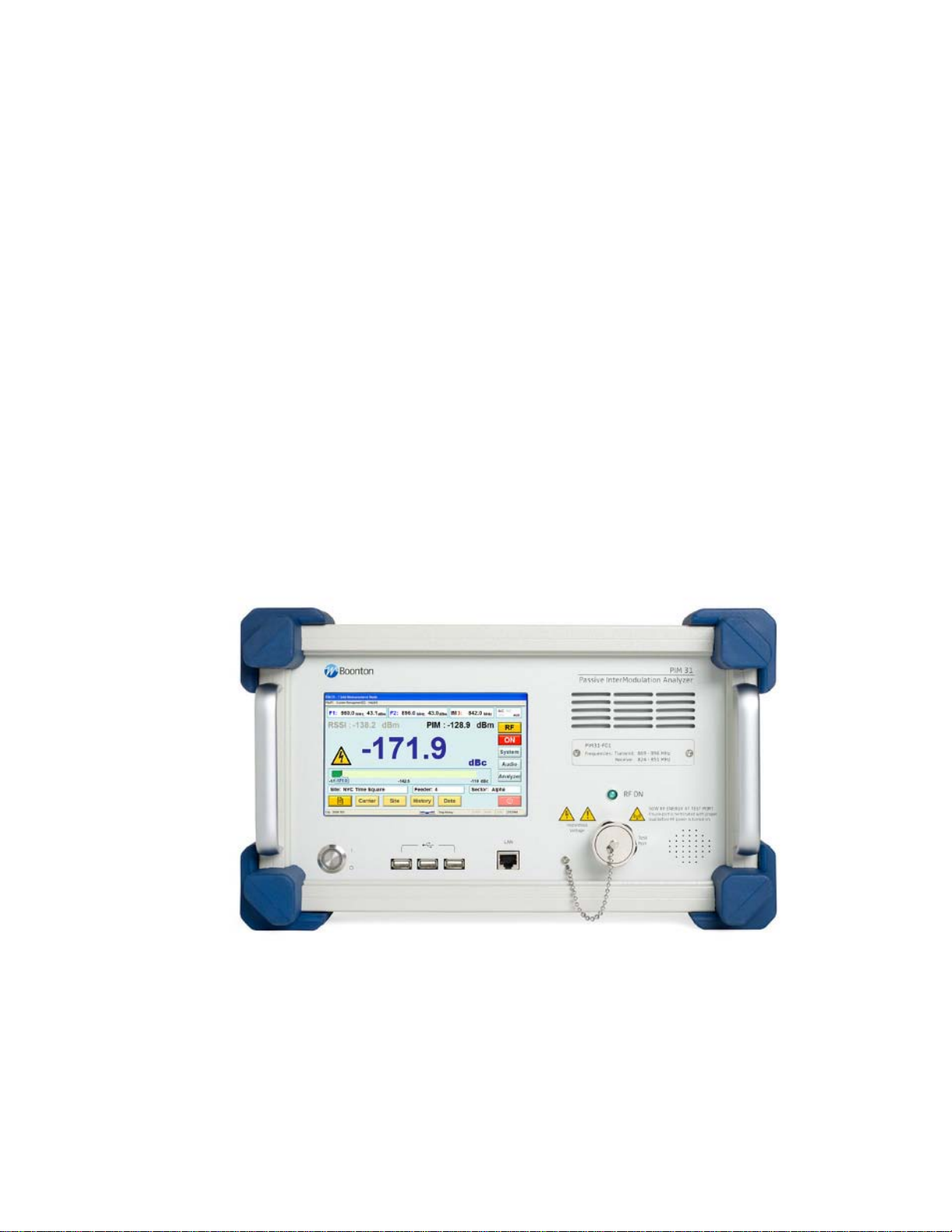
3 PIM 31 ELEMENTS ..................................................................................... 13
3.1 PIM 31 FR ONT PANEL ......................................................................... 13
3.2 PIM 31 BACK PANEL ............................................................................ 15
4 PRECAUTIONS ........................................................................................... 16
4.1 USING HIGH PERFORMANCE RF ACCESS ORIES ............................ 19
4.2 USING HIGH PERFORMANCE RF CABLE S ........................................ 21
5 POWERING PIM 31 UP/DOWN .................................................................. 22
5.1 Powering UP .......................................................................................... 22
5.2 POWERING DOWN .............................................................................. 23
6 GETTING STARTED ................................................................................... 25
6.1 THE FIRST MEASUREMENT ............................................................... 25
7 PIM 31 OPERATION ................................................................................... 29
7.1.1 Operations Men u Tree .................................................................... 31
7.2 FIELD MODE ......................................................................................... 32
7.2.1 Field Mode Elemen ts ....................................................................... 32
7.2.2 Carrier Entry .................................................................................... 34
7.2.3 Site Entry ......................................................................................... 37
7.2.4 Comments ....................................................................................... 39
7.2.5 History Screen ................................................................................. 40
7.2.6 Data Management ........................................................................... 41
7.2.7 Log Files and Content ..................................................................... 41
7.2.8 Log File Management ...................................................................... 43
7.2.9 Data Copy ....................................................................................... 43
3
Page 4

7.2.10 Data Delete Log Files .................................................................. 44
7.2.11 Data Delete Carrier & Site............................................................ 46
7.3 System Menu ......................................................................................... 47
7.3.2 System Menu Functional Block ....................................................... 49
7.4 Analyzer Mode ....................................................................................... 54
7.4.1 Frequency Mode ............................................................................. 56
7.4.2 Time Mode ...................................................................................... 57
7.4.3 Sweep Mode ................................................................................... 58
8 Pull Down Menus ......................................................................................... 61
8.1 File ......................................................................................................... 62
8.1.1 Start / Stop History Save ................................................................. 62
8.1.2 Screen Capture / Print ..................................................................... 63
8.1.3 Initialize Program ............................................................................ 64
8.1.4 Quit .................................................................................................. 64
8.2 System Management ............................................................................. 65
8.2.1 Self Check ....................................................................................... 65
8.2.2 PIMD Management ......................................................................... 66
9 Remote Application and TCP/IP Setup ........................................................ 67
9.1 Installation and connection setup for remote control: ............................. 67
9.1.1 Install PIM31 Remote Software ....................................................... 67
9.1.2 Known issues that might occur during installation on Windows OS:67
9.1.3 Setting IP address of PIM31 ............................................................ 67
9.1.4 Connecting PIM31 and PC. ............................................................. 68
9.1.5 Setting IP Address of PC ................................................................. 68
9.1.6 Check the network connection status of PIM31 and PC .................. 69
9.2 Using PIM31 Remote Application: ......................................................... 70
9.2.1 Enter IP address and Por t ............................................................... 70
9.2.2 List of remote commands ................................................................ 71
10 PIM31 Reporter Software .......................................................................... 72
10.1 Installation .......................................................................................... 72
10.2 PIM 31 Reporter settings .................................................................... 73
4
Page 5

11 What is PIM? ............................................................................................. 77
11.1 What Causes PIM? ............................................................................. 77
11.1.1 Manufacturing & Design ............................................................... 77
11.1.2 Mechanical ................................................................................... 77
11.1.3 Environment ................................................................................. 78
11.2 How to test PIM .................................................................................. 78
12 PIM 31 Technical Information ................................................................... 80
12.1 Tester Types....................................................................................... 80
12.2 Specifications (Data Sheet) ................................................................ 81
12.2.1 Transmitter Specification.............................................................. 81
12.2.2 Receiver Specifications ................................................................ 81
12.2.3 System Specifications .................................................................. 81
12.2.4 Environmental .............................................................................. 82
12.2.5 Dimensions and Weight ............................................................... 82
13 Maintenance ............................................................................................. 83
13.1 Block Diagram .................................................................................... 83
13.2 Performance Check ............................................................................ 84
13.2.1 Testing Analyzer operation status ................................................ 84
13.3 Performance Verification .................................................................... 86
13.3.1 Tx Signal Power Level ................................................................. 86
13.3.2 Tx Signal Frequency .................................................................... 88
13.3.1 Rx Power and Receiving Frequency ............................................ 90
14 Accessories ............................................................................................... 93
Appendix A ......................................................................................................... 94
Warrant y Statement ........................................................................................ 94
Appendix B ......................................................................................................... 96
EC Declaration of Conformity .......................................................................... 96
Appendix C ......................................................................................................... 97
Special Units Packing List ............................................................................... 97
Appendix D ......................................................................................................... 98
PIM31 F07 UL ................................................................................................. 98
5
Page 6

Manual Version Control ...................................................................................... 98
Contact ............................................................................................................. 110
6
Page 7
1 INTRODUCTION
Thank you for choosing a Boonton test system. The PIM31 is a high performance
instrument that allows users to make reliably, highly accurate measurements of
passive intermodulation, in systems and / or components. Our test systems are
built to the highest quality standards. We strive to provide the most reliable, state
of the art test equipment allowing our customers to have the utmost confidence in
the results of their testing. To ensure you can utilize all functions and features of
this test system, we strongly recommend you familiarize yourself with this manual
prior to operating your PIM31 test system. This manual contains valuable
information on the safe operation of the PIM31 test set and a brief technical
background on passive intermodulation.
7
Page 8
2 SAFETY SUMMARY
2.1 SYMBOLS
This safety requirement symbol (located on the rear panel) has
been adopted by the International Electro-technical Commission,
Document 66 (Central Office) 3, Paragraph 5.3, which directs that
an instrument be so labeled if, for the correct use of the instrument,
it is necessary to refer to the instruction manual. In this case it is
recommended that reference be made to the instruction manual
when connecting the instrument to the proper power source. Verify
that the correct fuse is installed for the power available.
The CAUTION symbol denotes a hazard. It calls attention to an
operational procedur e, pract i ce or instr uct i o n that, if not followed,
could result in damage to or destruction of part or all of the
instrument and accessor i es. Do not proce e d beyond a CAUTION
symbol until its conditions are fully understood and met.
The NOTE symbol is used to mark information which should be
read. This information may be very useful to the operation when
with the subject covered in this section.
The HINT symbol is used to identify additional comments which are
outside of the normal format of the manual, however can give the
user additional information about the subject.
8
Page 9
The following general safety precautions must be observed during all phases of
operation and maintenance of the Boonton PIM 31 Passive Intermodulation Test
System. Failure to comply with these precautions or with specific warnings
elsewhere in this manual violates safety standards of design, manufacture, and
intended use of the instrument. Boonton Electronics Corporation assumes no
liability for the customer’s failure to comply with these requirements.
INSTRUMENT MUST BE GROUNDED
To minimize shock hazard, the instrument chassis and cabinet must be
connected to an electrical ground. The instrument is equipped with a
three conductor, three prong AC power cable. The power cable must
either be plugged into an approved three-contact electrical outlet or used
with a three-contact to a two-contact adapter with the (green) grounding
wire firmly connected to an electrical ground at the power outlet.
DO NOT OPERATE THE INSTRUMENT IN AN EXPLOSIVE
ATMOSPHERE
Do not operate the instrument in the presence of flammable gases or
fumes.
KEEP AWAY FROM LIVE CIRCUITS
Operating personnel must not remove instrument covers. Component
replacement and internal adjustments must be made by qualified
maintenance personnel only. Never replace components or operate the
instrument with the covers removed and the power cable connected.
Even with the power cable removed, dangerous voltages may be
present. Always remove all jewelry (rings, watches, etc.) and discharge
circuits before touching them. Never attempt internal service or
adjustment of the test system unless another person, capable of
rendering first aid and resuscitation, is present.
9
Page 10
DO NOT SUBSTITUTE PARTS OR MODIFY INSTRUMENT
Do not substitute parts or perform any unauthorized modification of the
instrument. Return the instrument to Boonton Electronics for repair to
insure that the warranty and safety features are maintained.
NON IONIZING RADIO FREQUENCY RADIATION HAZARD
This device generates Radio Frequency (RF) energy under normal
operation, and should always be operated in accordance with local and
national licensing laws. RF energy in the 700 to 1,000 MHz and 1,800 to
2,200 MHz with a total power of up to 50W Watts or +47 dBm is present
at the test port during testing. The Test Port is to be terminated into a
non radiating 50 ohm load to reduce the risk of RF exposure. Do not
switch RF Power On if Test Port is open or load is unknown.
ELECTRIC SHOCK HAZARD
The device is supplied with 90 to 264 Volt AC. Prior to AC connection
always inspect the power cord and instrument cas e for da mag e. I f
damage is observed, do not use until inspected and repaired by an
authorized Boonton Service center.
2.2 DISCLAIMER
PIM 31 test systems transmit two settable CW RF signals, with a power of up to
25W each, to measure passive intermodulation of components and transmitting
systems.
Wireless Telecom Group and its subsidiaries are under no circumstances
accountable for use of PIM31 test systems not conforming to laws and
regulations of national and local authorities. Customer / user bear the full
responsibility and legal accountability to use PIM31 only in a lawful manner.
10
Page 11

2.3 POWER REQUIREMENTS
Caution
The PIM 31 Series is equipped with a switching power supply that provides
automatic operation from a 90 to 260 volt, 47 to 63 Hz, single-phase, AC power
source. Maximum power consumption is 750W / 750 VA
For bench-top use, choose a clear, uncluttered area. For field use,
choose a dust free environment. Ensure that there is at least 2" of
clearance at the fan air intake on the front panel and bottom vents,
and the exhaust vents on the back panels to allow for proper air
circulation.
Before powering the unit up make sure the instrument does not
show indications of exposure to extensive force like dents, torn off
pieces or loose parts in the case.
11
Page 12

2.4 PIM 31 SERIES PACKING LIST
PIM 31 Series Test Systems are shipped complete and are ready to use upon
receipt.
Note Save the original packing material and container to reship the
instrument, if necessary. If the original materials (or suitable
substitute) are not available, contact Boonton Electronics to
purchase replacements. Store packing materials always in dry
environment. If frequent used in the field with we strongly
recommend purchasing our PIM 31 Transit Case. See chapter
Accessories for ordering information.
Unless otherwise ordered * , your will receive:
• PIM 31 Series Passive Inter mo dulat ion Test System
• Line Cord with 90 deg connector
• USB Mouse
• USB Roll-Up Keyboard
• 2 Connector Savers
• Low PIM Cable 3m (10ft)
• Low PIM Load 50W
• Torque Wrench
* PIM 31 and accessories are available in customized versions / packages. Please refer to
Appendix A for specific package lists.
12
Page 13
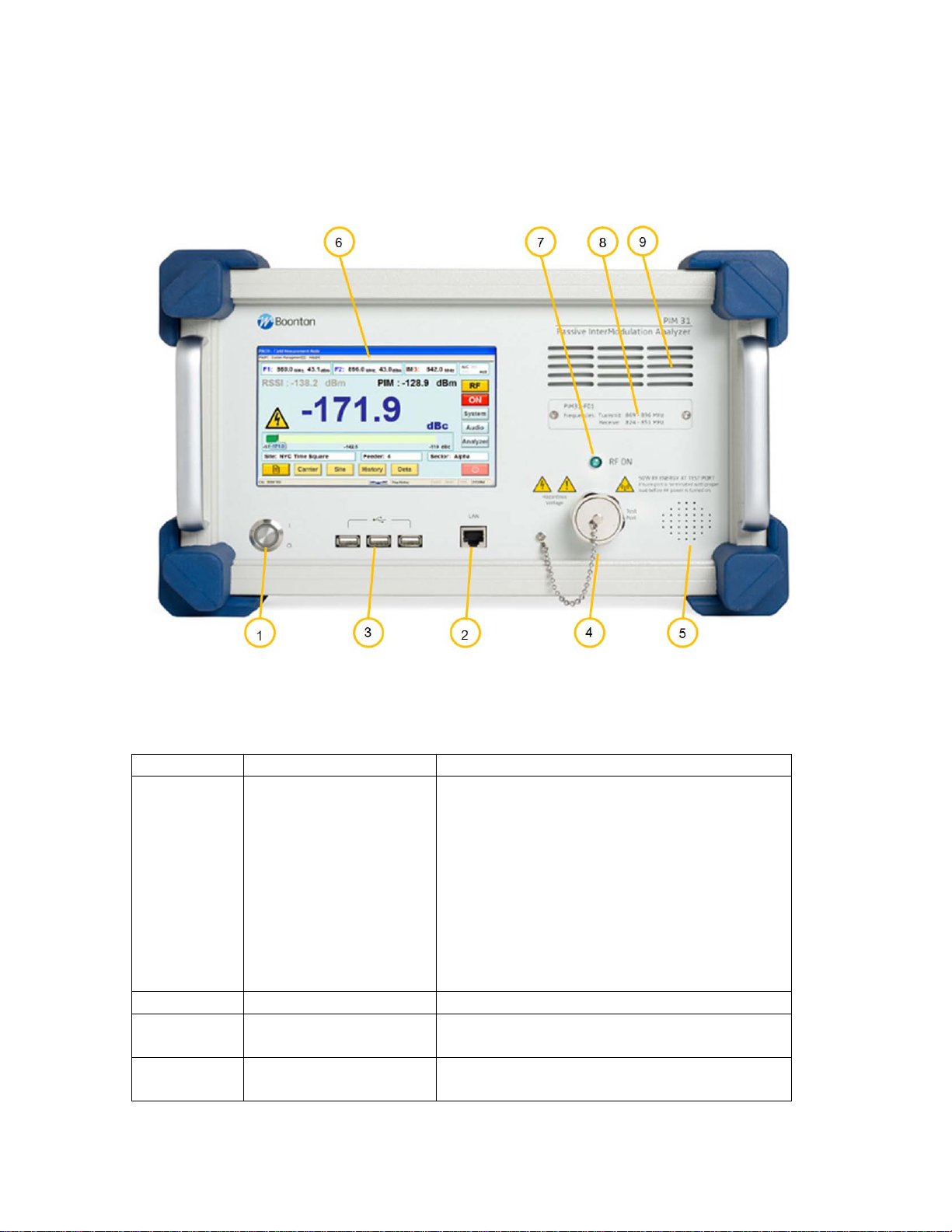
3 PIM 31 ELEMENTS
Number
Element
Description
1
Power Switch
Function similar to a PC:
must be in ON Position
2
LAN connector
For factory use only
3
USB Ports (3)
USB Ports for mouse, keyboar d and
Memory Stick
4
RF Port w/ protection
cap
RF Port,
Always use protection cap when PM31
3.1 PIM 31 FRONT PANEL
one short push – PIM31 powers up,
Another short push – controlled power
down
Holding it for 3 second – powers unit
down immediately
See also chapter Powering PIM31
up/down.
Note: Main Power Switch on the back
13
Page 14

is not in use.
5
Audio
Loudspeaker for audio si g nal s
6
Touch Screen
Display
Touch screen display 800x600.
on the screen
7
RF Power On
RF-Power light indicates when RF
Power is present.
8
Front Panel Air
Always allow for proper airflow, prevent
in.
9
Type Label
Provides information about PIM31 Tx/Rx
frequency bands
Never use sharp devices to push buttons
Vents
alien objects or dust from being sucked
14
Page 15
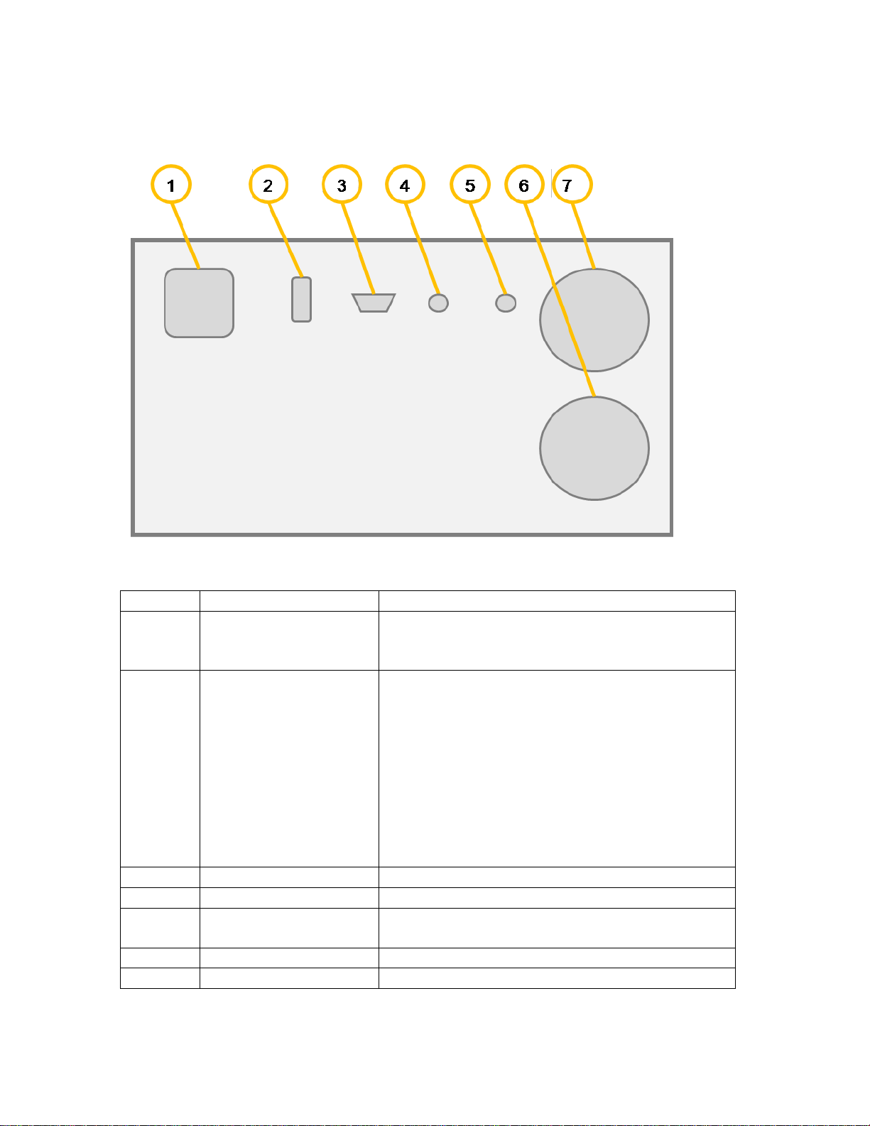
3.2 PIM 31 BACK PANEL
Number
Element
Description
1
Main Power supply
AC Supply: 90-264V, 7 50W / 750VA
Fuse: 4A / 230V or 8A / 110V
2
Main Power Switch
PIM31 contains protection circuitry to control
Button to power the system down.
3
VGA Port
Allows using an external VGA Monitor
4
Communications port
Factory use only
5
10 MHz Reference
out
10 MHz reference output to synchronize
external equipment
6
Air Flow Fan
Always ensure sufficient air flow
7
Air Flow Fan
Always ensure sufficient air flow
use 90 deg connector only
RF Power during operation and during
powering on/off cycles.
After switching Main Power Switch On wait 2
seconds before pushing Front Power Button.
Fans may Briefly run after power off.
Note: Do not use Main Power Switch while
system is in operation mode, vital files may
get corrupted Always use the Front Power
15
Page 16

4 PRECAUTIONS
Caution
Caution
Caution
DO NOT touch RF Connecting parts of components with bare
fingers.
Even the smallest amount of sweat on the conductors can cause
oxidation, which will reduce the performance of the element and
can cause PIM. Elements Included:
• RF Port of PIM31
• Low PIM Cables
• Low PIM Load
• Low PIM Adapters
• All components in the transmitting path of the System under
Test or DUT.
DO NOT switch on RF power without load or antenna attached.
Switching RF power on without termination, results in the full
transmitted energy of the test system being reflected back into the
test system. This can overstress the system cause damage. The
load ensures energy flow from the test system to the load, which
transforms all RF energy into heat.
DO NOT operate the PIM31 in any active systems.
The PIM31 is a very sensitive Test System that allows testing and
analyzing passive RF components. Under no circumstances should
the tester be operated w hen the RF path is active, no outside
carrier signals should be present in the RF path under test. This
includes all active signals even when they are operating in different
frequency bands. Operation with active signals present will cause
serious damage to the i nst r um ent.
16
Page 17

Caution
Caution
Caution
DO NOT connect or disconnect any accessory or component
of the test setup with RF power switched on.
Even at low RF power levels, spark discharge can occur with
sudden energy flow or flow disruption.. Spark discharg e - must be
avoided, because it will alter the surface of the pins and connection
areas. “Burned” surfaces will not only reduce the performance of
the component, but can also cause permanent PIM.
DO NOT operate test system and load without connector
savers.
All connectors wear out when used frequently. Connector savers on
the RF Port and the load port(s). help to prevent costly repairs of
the PIM31 Boonton connector savers offer negligible influence on
measurements. We suggest to always leaving the connector saver
attached to the tester / load to ensure they are always utilized.
Replace them when they wear out, and their performance
deteriorates. For order information please refer to the chapter
accessories.
DO NOT mount components directly on the PIM31.
Always use a cable between PIM31 and DUT. The connector of the
PIM31 is a high quality, high precision element. It is designed to
withstand tangential forces that occur when connector savers or
cables are torqued on with the appropriate force. The RF Port
connector is not designed to support the weight of a component.
17
Page 18

Caution
Caution
DO NOT block air vents.
Due to its high RF output power, PIM31 consumes up to 750W.
This energy has to be disposed. While these test systems have
protection against overheating, it is vital to keep air vents clear of
any obstructions that would prevent or limit the air flow.
Air vent locations
• Front Panel
• Back Panel
• Bottom
Keep clearance at least 15 cm / 6 inches for Front and Back Panel
Vents, and 4cm / 1.5 for the bottom vent.
DO NOT bent cable tighter than 40 cm / 16 inches of diameter.
Caution
Cables that come with the PIM31 offer a combination of high
quality, low PIM, and high reliability. The test cable is a vital piece
of the measurement setup, and a damaged or worn cable will
influence PIM measurements... The structure of Boonton’s PIM
cable offers customer friendly utilization in the field and in the
factory it allows for a bending radius of 20 cm / 8 inches. Tighter
bending will permanently alter the cable structure, which will cause
performance loss and can ca use per m an ent PIM , rend er i ng the
cable unusable. See also chapter: Using the Cable.
DO NOT over-torque the RF Port connector and accessories.
The best performance of RF connectors is achieved when the
connections are made with the correct torque. Too much of a
torque can permanently deform PINs and connections areas, too
little torque can hinder the electron flow, varying the impedance or
in some cases can cause spark discharge. All these effects can
damage the components permanently. To ensure proper
connections always use the torque-wrench that comes standard
with the PIM31.
18
Page 19

Caution
DO NOT use sharp devices at the touch screen.
Users can operate PIM31 test systems but utilizing the touch
screen or via keyboard/mouse. The user interface is designed
specifically for field use; all vital operations can be conveniently
accessed via the touch screen interface. Do not use sharp devices;
they can damage the touch screen. The touch screen, display and
CPU are a single integrated module. In case of service the
complete module has to be exchanged. To prevent costly repairs,
use only your fingers or very dull devices to interact with the
screen.
4.1 USING HIGH PERFORMANCE RF ACCESSORIES
PIM test sets combine very high output power, with extremely sensitive receivers.
Note: The sensitivity of the PIM 31 receiver is many times greater than the
sensitivity of a Base Station. Any unwanted influence generated by poor
performing accessories will reduce the accuracy of the desired measurement. To
ensure quality measurements great care has to be taken; not only for the test
system but also for the cables and accessories. Remember you want to measure
the PIM of the device under test, not a poor performing or worn accessory.
Prevent unnecessary force:
Nearly all RF connectors are designed to allow for manual
connection. To ensure a proper connection, RF connectors should
be manually mated, push in to seat the center pin, then hand
tightened until seated. The torque wrench should only be used to
tighten the last ½ turn or less. Improper connections will cause
performance loss. This includes under torquing and over torquing.
Both, over and under-torquing, result in weak connections which
contribute to PIM. Over tightening may damage the connector and
lead to visible metal fragments in the connector’s surface. All
damaged connectors and connectors savers should be replace
prior to testing.
19
Page 20

Keep Accessories clean:
Dust and dirt may affect test results. Make sure accessories are
stored properly and clean. Please use the protective caps - to keep
the accessories free from contamination. Never use sharp devices
to remove any contamination because scraping can cause metal
chips in the contact areas, which will generate PIM. If any dirt,
corrosion or any other foreign matter needs to be removed use
special RF contact cleaning tabs and / or compress ed air.
Keep Accessories dry:
Even the best plating will wear if accessories are frequently used.
Moisture will cause oxidation. Prevent moisture by using supplied
protective caps and keeping accessories stored properly. Many
connectors are weather sealed to prevent moisture from enteri ng
the contact area. If you discover moisture use RF contact cleaning
tabs and blow dry with compressed air.
Check for wear and tear :
All metal to metal surface subjected to movement will eventually
show the effects of wear and tear. In the case of PIM
measurements the results appear as an increase in PIM level.
Check your accessories frequently to ensure that they are working
properly. Once you have determined that an accessory is no longer
performing as it should, replace it with a new device. When you
received the replacement, dispose of the old one to prevent
accidental reuse. Check chapter on Accessories for ordering
information of spare and replacement accessories. Accessories are
key to accurate PIM measurements. Although properly functioning,
they are also wear and tear items and will need to be replaced.
20
Page 21

4.2 USING HIGH PERFORMANCE RF CABLES
Cables are as vital to proper PIM testing as any of the other accessories are.
Treat them with the appropriate care. All hints listed above for accessories apply
to cables as well. Always use cable caps to protect connectors when the cable is
not in use. The bending radius for the PIM31 cable delivered by Boonton is 20cm
/ 8 inches. To prevent damage, coil cable no tighter than 40 cm / 16 inches in
diameter. A transit case for PIM31 systems is available. This case has dedicated
space for test systems, accessories and also the low PIM cable. For more
information please refer to the chapter on accessories.
“Treat accessories and cables for what they are:
High precision measurement devices”
PIM tests measure the device in the testing path that generates the highest level
of PIM. Worn or malfunctioning accessories lead to inaccurate measurements.
Remember you want to measure the PIM level for the RF path or device under
test, not a worn accessory or test cable. Inspect your accessories and cables
prior to each use, and treat them as part of a high precision me asurement
device.
21
Page 22
5 POWERING PIM 31 UP/DOWN
5.1 Powering UP
PIM 31 test systems power up in a similar fashion to a desktop PC. However,
there is one exception: significant RF power has to be controlled and managed..
For this reason PIM 31 series test systems contain a protection system to protect
the hardware, e.g. prevents unusual on/and off cycles ( e.g. 3 cycles per
second). When used normally, the user will not even recognize that these
protective mechanisms are working.
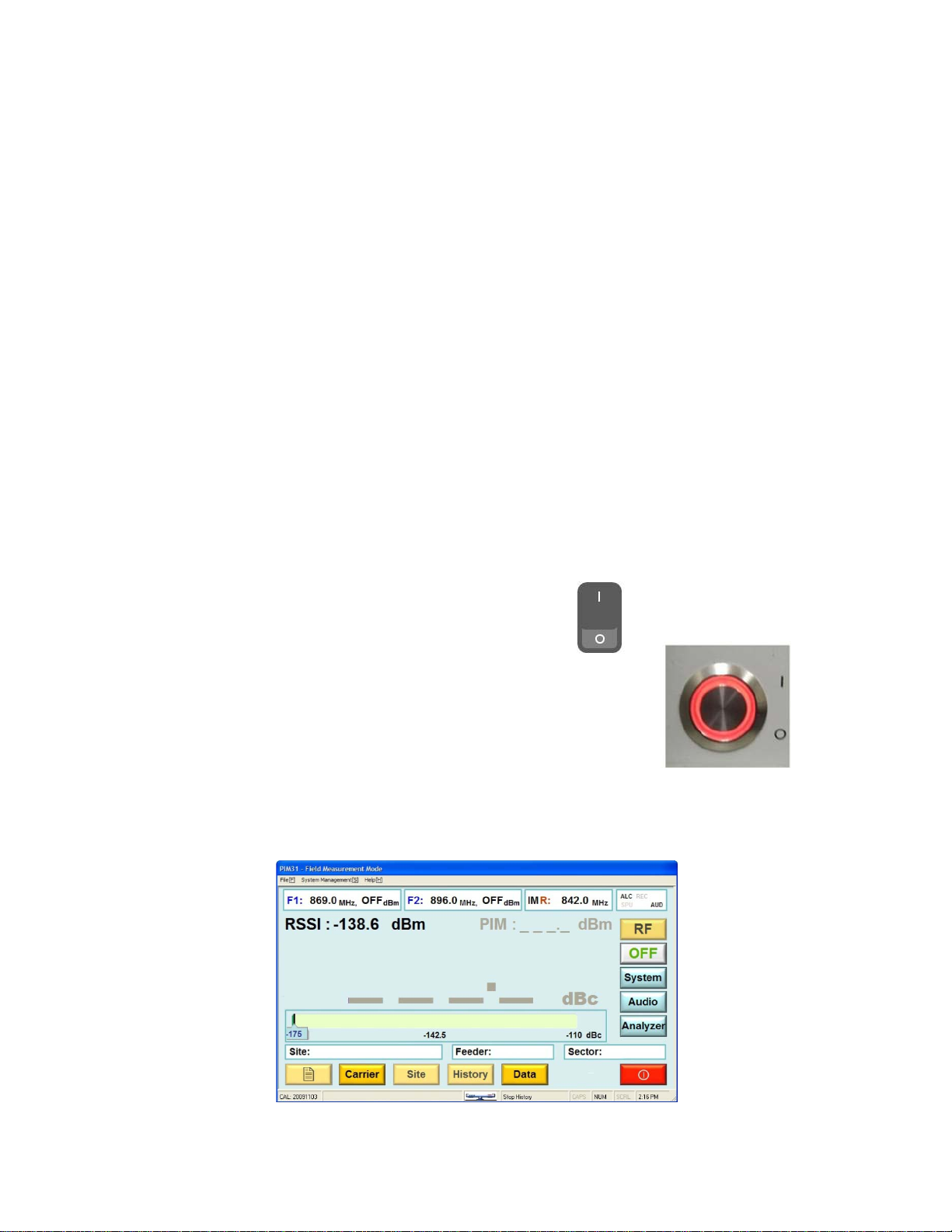
Preparations for powering up:
Ensure that the main outlet has pr oper gr ou nding.
Connect the correct power cable to the tester
Connect the power cable to the main outlet
• Switch on the PIM31 main power switch at
the backside of the unit. Allow for a short
delay before switching on front power
button. (This will allow protection circuitry
to enable all PIM 31 modules).
• Push Start Button briefly at the front panel.
The system will boot up automatically and show the user interface in the Field
Mode.
22
Page 23
Caution
Caution
5.2 POWERING DOWN
PIM31 can be powered down in different ways listed below. It is not
recommended to power down simply by “Pulling the plug” or
switching off the Main Switch on the back panel.
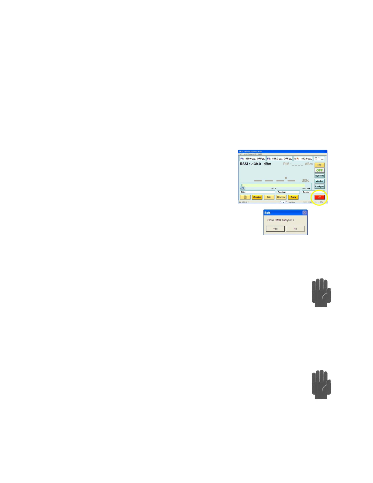
Exiting
The proper way is to Exit the UI is by pressing the
red exit button. This will generate an exit pop up.
Respond to the pop-up menu’s choice Yes / NO to
power the system down or not. This method ensures
the RF is switched off properly, all UI and computer
processes are terminated in an orderly fashion, and
data files are closed.
Forced Termination
Holding the Start Button on the front panel for 3 seconds generates a soft
reset. RF is switched off, and all vital files will be closed and stored. In
this mode, the urgency to power off the unit trumps handling and closing
all files. Some information, e.g. log data may be lost.
Main Switch
When not following the proper shutdown sequence and using the Main
switch on the back to terminate power it is likely that files get corrupted,
and the test system may be harmed.
Note: Cooling fans may become operational after the main switch is
placed in the off position until discharge of all internal capacitors is complete;
typically within 5 seconds
23
Page 24

Caution
“Pulling the Plug”
This “method” should be avoided under all circumstances. It can
damage the hardware and corrupt files. This “method” is
especially critical if the RF port is still connected to a grounded
system under test. Residual discharges may flow via RF Ground /
Shield. With the main connector no longer plugged in, ground
connection is also disrupted.
24
Page 25
6 GETTING STARTED
Before starting to measure components with PIM31 systems, users are urged to
familiarize themselves with the precautions (Don’ts) in the chapter below.
Improper operation and handling can cause bodily harm or damage the
instrument.
6.1 THE FIRST MEASUREMENT
Preparations:
• Mount connector saver to RF Port and Load (if not already mounted)
• Connect Low PIM cable to Test system (Note: always connect the test
cable to the instrument prior to connecting to the DUT)
• Connect Load to cable.
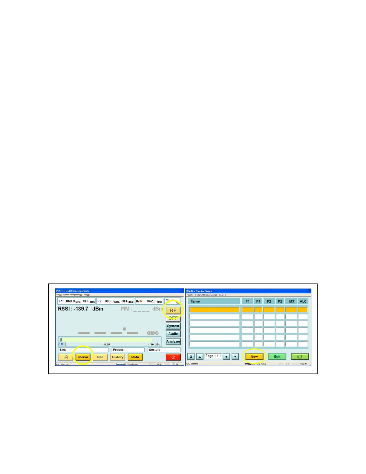
At this point the RF Button is visible but inactive. Power levels and the
frequencies of the carrier signals must be set in or der to act i v at e the RF button.
To do so, pushing the “Carrier” button displays a list of Carrier signal settings.
Since this is the first boot up, the list is empty. To enter carrier parameters, push
“New” at the Carrier Select screen. Now we can enter a Carrier name,
frequencies and power levels. With growing list of carriers, meaningful carrier
25
Page 26
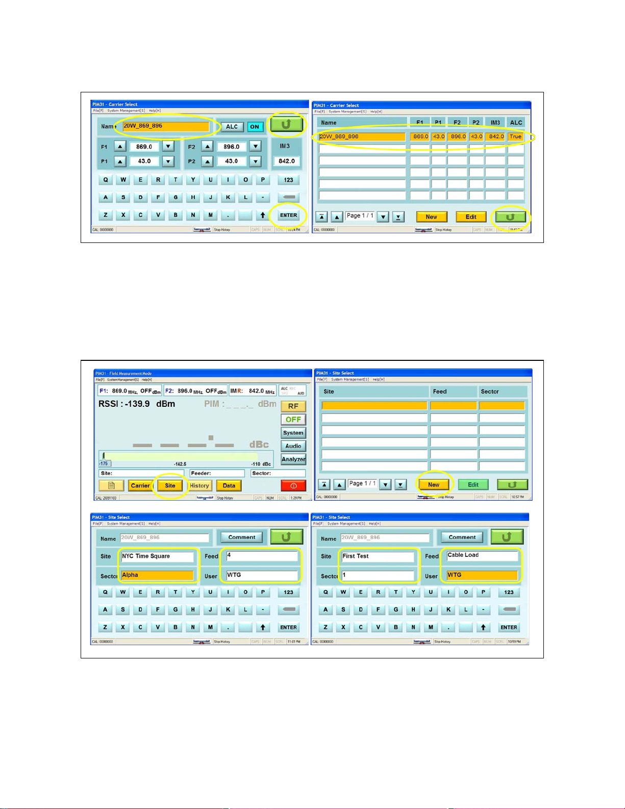
names help to recognize the settings: Example 20W_869_896 means: power of
the signals is 20W, and the frequencies used are 869 MHz and 896MHz.Every
entry or change needs to be confirmed by pushing the “Enter” button. Once our
entries are complete, we return to the previous screen, “Carrier List” by pushing
the green Return button. The list shows now a carrier entry. By pushing the
Green return button we come back to the Field Mode screen.
26
Page 27
PIM 31 test systems provide not only accurate PIM analysis, they also allow
users to log data that is specific to a particular test setup or particular base
station site. At a later point, measurements can be recalled for comparison and to
analyze if the performance has changed. This particular information has to be
entered as well. The process is similar to the Carrier entry, except this time we
push the “Site” button. As with the carrier, the system lists all available Sites (or
Tests). Since we have not entered a Site the list is still empty.
Note: Site information is linked to particular Carriers. If a different Carrier
is selected the associated list of Sites (Tests) corresponds to Sites that
were entered under this Carrier.
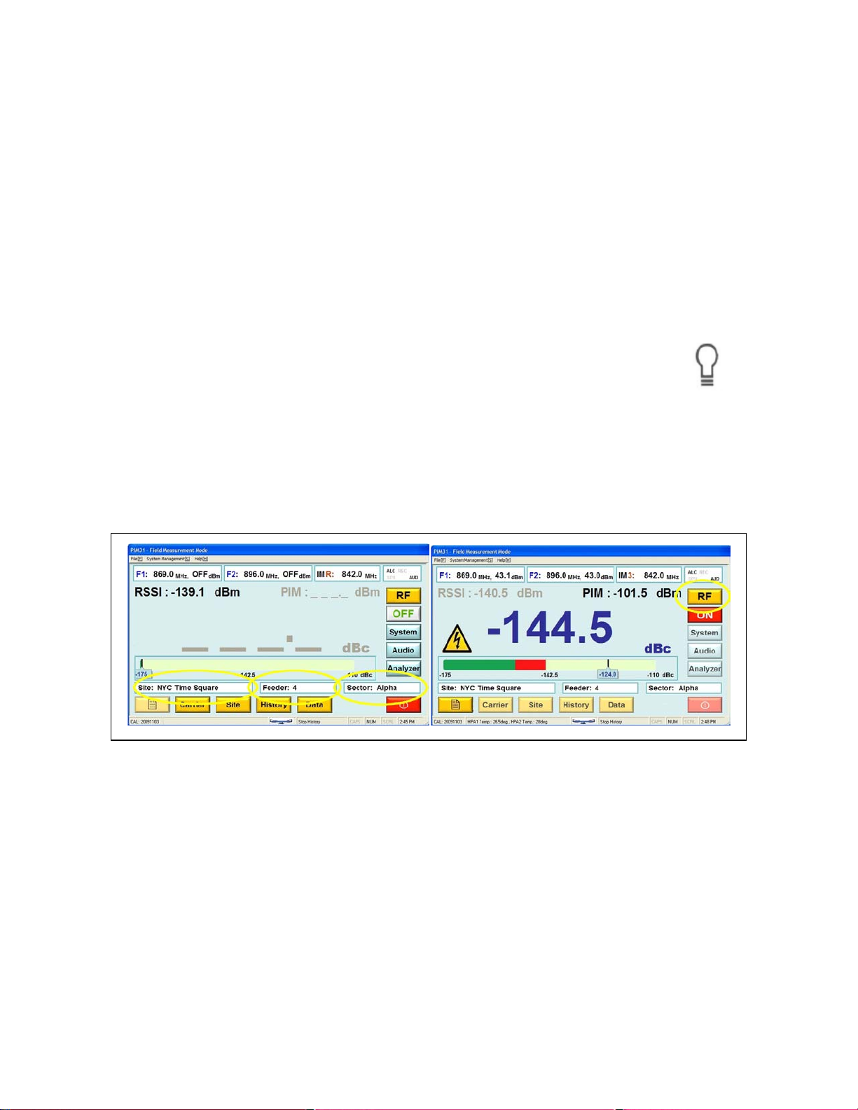
Now we can enter detailed base station or measurement setup information. Once
completed, we return to the initial Field Mode Screen. The selected Site (Test)
information is now visible in the appropriate fields and the RF Button is now
active.
27
Page 28
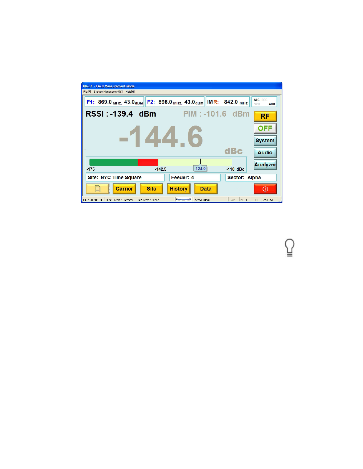
By pressing the RF Button, the system initializes, and starts measuring PIM. A
second push of the RF button stops measurements and transmission of RF
signal carriers. The last PIM reading is held and shown in grey.
Note: PIM 31 test systems switch RF Power off after 30mins (default).
Other cycles or “Always On” can be selected. For more information
refer to chapter System Menu.
28
Page 29
7 PIM 31 OPERATION
PIM31 Test Systems were developed to measure and analyze PIM data of RFcomponents, cables, or complete RF systems.
Operation Modes for Different Applications: Field Mode / Analyzer Mode
Depending on the application, the users’ requirements will be different. The main
task at a base station site is to quickly analyze the RF Path, and document the
measurements. If unacceptable PIM levels are detected the PIM31 can be used
to identify and pin-point problematic components. When testing base stations,
typically, the frequency and power settings of the test equipment are site specific.
Focus lies on quick measurement and documentation of data. PIM31 test
systems provide this easy to use functionality in the Field Mode. All base station
test parameters can be stored in the PIM31 test system, including feeder and
sector information. By selecting the base station, the user is ready to go. For
preventive maintenance it can be very helpful to compare actual with historical
data, which the PIM31 offers this as well. Measurements can be stored in the
system as .log files. Whenever data are logged, the log field stores
measurements, test system settings, and even complete information of the base
station. The operator can view the historical data of a base station at any time
and analyze if readings have changed compared to historical measurements.
29
Page 30
Similar conditions apply when components are tested. The instrument settings do
not change, but for quality reasons every measurement has to be documented.
For measuring RF Components, the Field Mode is a very comfortable and
efficient
If more detailed information about the DUT is required, it can be accessed by
using the Analyzer Mode of the PIM31 test system. In this mode the user can
analyze multiple intermodulation products at the same time (Frequency Mode),
can record graphical traces over a longer time period (Time Mode) and can
frequency sweep DUTs (Sweep Mode) to ensure it performs within the complete
frequency band within specification.
The following chapters Field Mode and Analyzer Mode provide more detailed
information.
30
Page 31

7.1.1 Operations Menu Tree
PIM 31 Test systems are designed to provide an efficient workflow. The Menu
Tree shows the overall menu structure of the PIM31.
31
Page 32

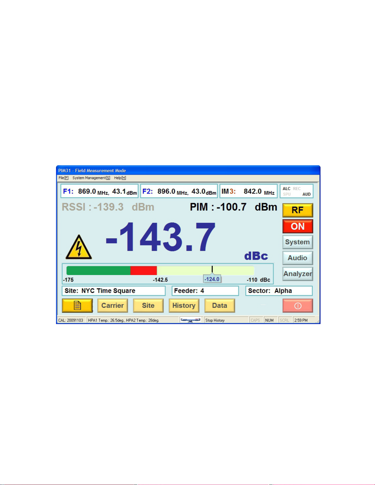
7.2 FIELD MODE
Element
Name
Description / Display
A
File Menue
Pull down Menu, choices:
See also chapter Pull-down Menus
B
Carrier Field:F1
Shows Frequency (MHz) and Power level(dBm) of first
carrier signal.
C
System management
Pull down Menu, choices:
See also chapter Pull-down Menus
E
Carrier Field:F2
Frequency (MHz) and Power level(dBm) of second
carrier signal.
F
PIM Value dBm
Measured PIM value numerically in dBm. Displays last
value after RF Power is turned off.
G
IM Frequency
Frequency (MHz) if strongest IM signal in the receiving
band and indicates which IM it is (3,5,7,9,11,13 or 15).
H
Status Indicator Field
Shows status and activities of PIMM31:
ALC – Automatic Level Control
7.2.1 Field Mode Elements
The following chapter desc ribes the Display elements of the F ield Mode screen.
“Quit”, same function as Exit Button
“Self Test”, tests PIM 31 functionality with RF ON and
OFF
32
Page 33

AUD – Audio On
REC –Data Recording
SPU – Soft Power Up
I
RSSI
RSSI (Received Signal Strength Indication) in dBm.
-130dBm.
J
PIM Value dBc
Measured PIM value numerically in dBc. The unit dBc
Displays last value after RF power is turned off
K
Voltage at the RF-port can reach up t 50V.
L
Bar Graph PIM
Graphical display of PIM measurement. Range is:
M
Display fields (3)
Detailed Information of selected Site (e.g. Base Station
20W_Combiner_Test”
N
RF On / Off Switch
One Push switched RF ON,
Carrier Select and Site Select
O
RF Indicator light
Indicates when RF-power is ON
P
See Chapter System Menu for further information
Q
Audio On/Off
Audio Signal when measurement passes green/red
threshold of Bar Graph
R
For more information see chapter Analyzer Mode
S
EXIT
Triggers Power down sequence.
Active only when RF-power is OFF.
T
see chapters Data and System Menu
U
Carrier
Opens Carrier Select screen.
Active only when RF-Power is OFF
V
Site
Opens Site Select screen.
Active only when RF-Power is OFF
W
History
Opens Site History screen
Active only when RF-Power is OFF
X
Data
Opens Data menu (copy log files, delete log files, sites
External signals at the receiving frequency / frequencies
may disturb PIM measurements. For accurate PIM
measurements RSSI should always be below
describes a measurement relative to the carriers, in this
case the carrier signals transmitted by the test system.
Voltage Warning Warning Sign appears when RF Power is switched on.
indicator
Site, Feeder, Sector
System Opens System menu.
Analyzer Opens Analyzer Menu
Record In single mode (default), log measurement and system
-175dBc (start green bar) to -110dBc (end red bar).
Default threshold green/red is -153dBc. See System
Menu for further information.
Location), and Site specific information like Feeder line
and antenna sector.
Also often used to describe test setup, e.g. “Site:
Second push switches RF ON.
The button is only active if Carrier parameters have
been set and Site information is available.
For further information see menus:
data of current measurement.
In auto mode, start/stop for recording continuous log
sequences.
For further information on recorded data and auto mode
For more information see chapter Carrier Select:
For more information see chapter Site Carrier:
For more information see chapter Site Carrier:
33
Page 34

and carriers)
For more information see chapter Data
Active only when RF-Power is OFF
7.2.2 Carrier Entry
Carrier Signal settings specify the frequencies of the transmitting RF signals and
their power level. Site information allows to a) specify the tested site in detail or
to specify component tests more closely. All settings entered with Carrier signals
or Site/Test information are recorded when measurement data is logged, this
allows for detailed analysis after a series of tests has been completed.
Furthermore settings and vital measurements are stored in the system so that
historical data related to site information can be viewed for comparison, e.g. if
systems are deteriorating. For more information on this see chapter “History
Screen”.
Carrier Select
Once carriers have been stored in the system, they can be easily recalled. The
screenshot shows a list of 2 carriers with related information on transmit
frequencies and power levels.
34
Page 35

Element
Name
Description / Display
A
Carrier
Carrier specific information on frequencies and
power levels stored in the PIM31.
B
Selected Carrier
The yellow background indicates the carrier that is
selected and will be used for test after pressing
Return
C
Page Indicator &
If more than 6 different carrier signals are stored in
Carriers are selected by clicking / tapping them.
D
New
Opens Edit Carrier screen without carrier name.
cannot be changed (only deleted) at a later time.
E
Edit
Opens Carrier Edit screen, allowing the
modification of frequencies or power levels.
F
Return
Returns to previous screen.
Jump arrows
PIM 31 Carrier Edit
the PIM31, the current page and number of pages
are shown.
Inner arrows: One page jumps in both directions
Outer arrows: Jump to Pos1 or End of list
Note: Once the carrier name has been entered, it
35
Page 36

Element
Name
Description / Display
A
Carrier 1
Parameter
Sets power level and frequency of carrier signal 1:
by pushing the Enter button (I)
B
Carrier Name
When entering new carrier information, the cursor
The name will be stored by pushing “Enter” (I)
C
Carrier 2
Sets power level and frequency of Carrier Signal 2:
by pushing “Enter” (I)
D
ALC
Auto Level Control – for utmost accuracy it is
For more information see chapter “System Menu”.
E
Return
Returns to previous site.
F
IM
Automatically calculates and displays the next IM
product that lies in the receiving band of the PIM31
G
123 / ABC
Toggles the touch screen keyboard between
characters and numeric.
H
Delete
Deletes last character / character to the left of the
cursor
I
Enter
Entries are stored in the system when the “Enter”
button is pressed
J
Keyboard
Keyboard, toggles between characters and
numeric
K
Space
Space
L
Capitals
Upper case entries
Note: when entering this field a numeric keyboard
is displayed. A new or changed value is accepted
is set to this field and marked orange for editing.
Parameter
Note: when entering this field a numeric keyboard
is displayed. A new or changed value is accepted
recommended to set ALC to ON (default).
Note: When using an external keyboard do not use commas in
names or descriptions. Log Data is stored in a CSV (Commaseparated value) text form. Commas in the description will mix up
fields that are assigned for particular values, relevant e.g. when
importing data in a spreadsheet or database. The touch screen
keyboard does not offer commas for entry.
36
Page 37

7.2.3 Site Entry
Element
Name
Description / Display
A
Site
Sites, with information on feeder and sector stored
in the PIM31.
B
Selected Site
The yellow background indicates that this site is
selected and will be used for data logging.
C
Page Indicator &
If more than 6 different sites are stored in the
Sites are selected by clicking / tapping them.
D
New
Opens Edit Site screen without site name.
cannot be changed (only deleted) at a later time.
E
Edit
Opens Site Edit screen, allowing the modification
of site related infor mation.
F
Return
Returns to previous screen.
As with Carriers, Sites (or Tests) and linked information can be stored in the
memory of the PIM31. Once Sites have been stored in the system, they can be
easily recalled. The screenshot shows a list of 4 Sites with related information on
feeder and sector.
Jump arrows
PIM31, the current page and number of pages are
shown.
Inner arrows: One page jumps in both directions
Outer arrows: Jump to Pos1 or End of list
Note: Once the site name has been entered, it
37
Page 38

PIM 31 Site Edit
Element
Name
Description / Display
A
Carrier Name
Carrier signal to which site information is related to.
B
Comment
Allows additional entries related to the Site or Test.
C
Site / Test Name
Site / test name
“Enter” (J)
D
Sector
Additional information (Sector)
“Enter” (J)
E
Return
Returns to previous site.
F
Feed
Additional information (Feeder)
“Enter” (J)
G
User
Additional information (User)
“Enter” (J)
H
123 / ABC
Toggles the touch screen keyboard between
characters and numeric.
I
Delete
Deletes last character / character to the left of the
cursor
J
Enter
Entries are stored in the system when the Enter
button is pressed
New or changed entries are stored by pushing
New or changed entries are stored by pushing
New or changed entries are stored by pushing
New or changed entries are stored by pushing
38
Page 39
K
Keyboard
Keyboard, toggles between characters and
numeric
L
Space
Space
M
Capitals
Upper case entries
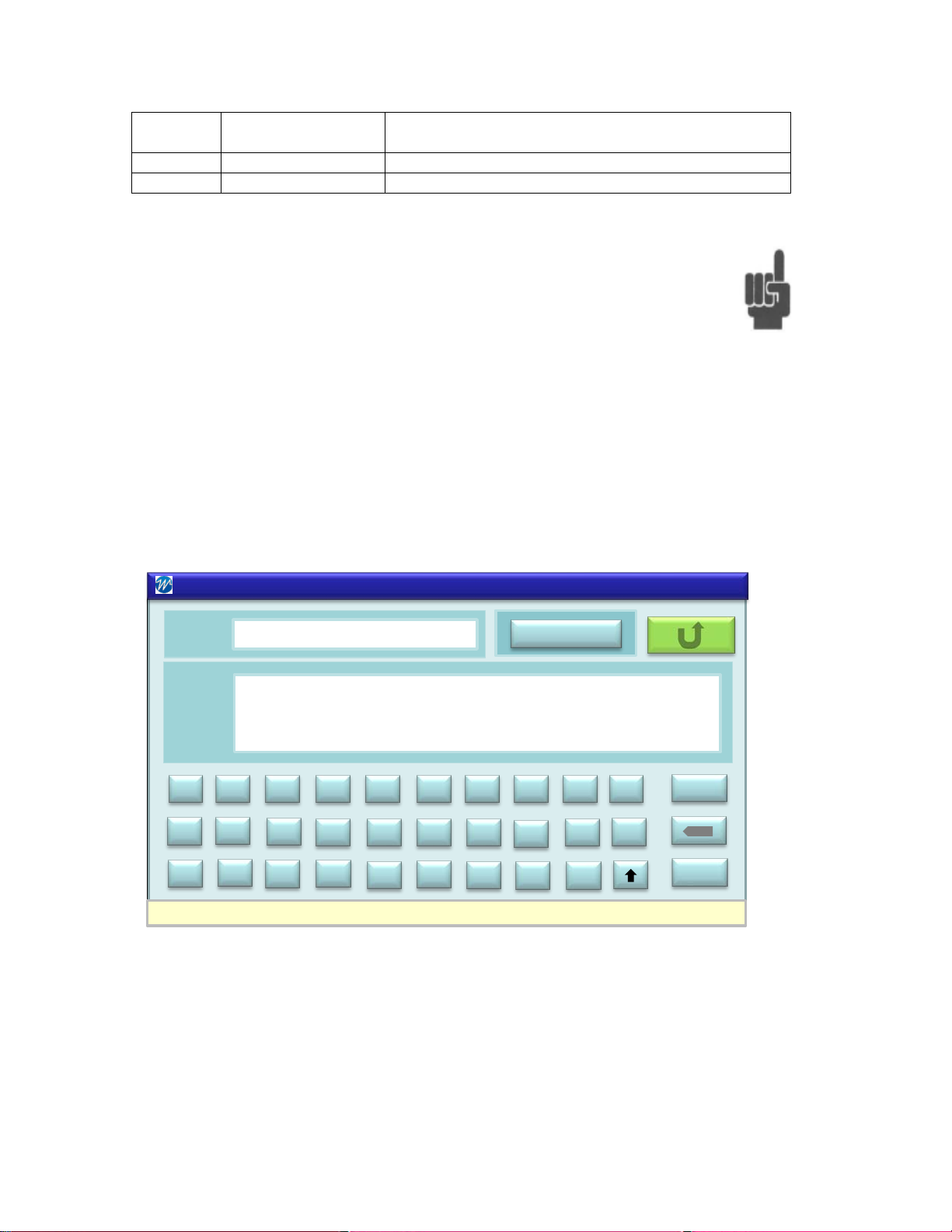
Name
Carrier 1
PIM 31 – Site Information - Comment
Site Info
123
More
Site
Info
Feeder Alpha shows sporadic PIM values up to - 83.5 dBc. High RSSI
readings.
ENTER
A
B
C
D
E
F JG H
I
K
L
M
N
O PTQ R
S
U
V
W
X
Y
Z
.
-
Note: When using an external keyboard do not use commas in
names or descriptions. Log Data is stored in a CSV (Commaseparated value) text form. Commas in the description will mix up
fields that are assigned for particular values, relevant e.g. when
importing data in a spreadsheet or database. The touch screen
keyboard does not offer commas for entr y.
7.2.4 Comments
Site information allows users to add comments that provide further information
about the Site or the Test. Comments are not stored in the log file.
39
Page 40

7.2.5 History Screen
Element
Name
Description / Display
A
Site
Site (test) information including Site name, Feeder,
and Sector
B
Log Data Set
Shows historical information of measurement:
levels and RSSI
C
Log Data Set
As in A. The cursor is just for visually aiding the
user.
D
Page Indicator &
If more than 6 different sets of log data are stored
Outer arrows: Jump to Pos1 or End of list
E
Return
Returns to previous site.
Log data is stored in the test system memory whenever the REC button is
pushed. Log data stores the measurements, tester settings, and site related
information. With this capability operators can view historic information of specific
sites, allowing them to compare current and former measurements and analyze if
their performance has chang ed over time..
Jump arrows
Date, Time, PIM reading, Frequencies, Power
in the PIM31, the current page and number of
pages are shown.
Inner arrows: One page jumps in both directions
40
Page 41

7.2.6 Data Management
The following chapter desc ribes the Data Menu and Data structure.
Recording / Record - Button
PIM31 can store measurement data manually (default) or automatically with
predetermined intervals. When the “Record” button in the “Field Mode” screen is
pushed, the system stores one data set in a log file. The recorded measure men t
data is stored in a log fil e. This file is stored in ASCII text format with CSV
structure. (Comma -Separated Values), allowing convenient importing of log data
into databases or spreadsheet applications.
For more information about Automatic Mode refer to chapter “System Menu”.
Note: While it is theoretically possible to enter commas in descriptive
fields like Carrier Name, Site, Feeder and Sector, it is strongly
suggested to refrain from such practice. In a CSV structure, text after
the comma will be taken as new value when importing into a database
or spreadsheet which will mix up field assignments. Important
information will be at an incorrect location.
7.2.7 Log Files and Content
With PIM31 firmware versions 1.2 and later, log file names are a combination of
Carrier, Site, Feeder, Sector, Date and Time. This way every log data file is
absolutely unique and allows for easy identification:
PIM31_SITE_FEEDER_SECTOR_YYYYMMDD_HHMMSS.log
Previous firmware versions used the nome ncl atur e:
PIM31_YYYYMMDD_HHMMSS.log
Log files are stored in the directory C:/PIM 31 /History
Users do not need to access this directory directly since the data features of
PIM31 test system offer a convenient way to extract and copy the data.
Information stored in log files is listed in the table below.
41
Page 42

Content (comma separated)
Variable
Format
Description
Date
YYYYMMDD
Time
HHMMSS
PIM (dBc)
-XXX.X
Signed Field
PIM (dBm)
-XXX.X
Signed Field
RSSI (dBm)
-XXX.X
Signed Field
F1 (MHz)
XXXX.X
Frequency 1 in MHz
F2 (MHz)
XXXX.X
Frequency 2 in MHz
IM 3 (MHz)
XXXX.X
IM3 Frequency in MHz
F1 (dBm)
XX.X
F1 Power level in dBm
F2 (dBm)
XX.X
F1 Power Level in dBm
IM3 Bandwidth (Hz)
XXXXX
IM 3 Bandwidth in Hz
PIM 31 Type
XXX
Example: “F03”
Model
String - 40 Characters max
Serial Number
String - 40 Characters max
Serial number of test system
HW Version
String - 40 Characters max
Hardware version
SW Version
String - 40 Characters max
Software version installed
OS Version
String - 40 Characters max
Operating system
Carrier
String - 70 Characters max
Carrier name
Site Name
String - 70 Characters max
Site / Test description
Feeder
String - 40 Characters max
Feeder description
User
String - 70 Characters max
User name / Initials
“Wireless Telecom Group”
String
For internal use
“PIM 31 Data Log”
String
For internal use
Cal date
YYYYMMDD
Date of Last Calibration
CHKSUM
XXX
For future use
SECTOR
String - 40 Characters max
Sector description.
BarGraph_RG
-XXX
Value of Bar Graph green /red
threshold (–dBc).
RFON
String:
RF On time in seconds,
120m,180m or “Always On”
RECINTRV
String
Lists Recording interval time
and units or “OFF”
ALC
String - 3 Characters max
“ON” or “OFF”
Added with firmware version 1.2 and later.
1m,2m,5m,10m,20m,30m,60m,
42
Page 43

7.2.8 Log File Management
Element
Name
Description / Display
A
Copy location
Drive, directory and file name of the merged log data
file.
B
when related log data are erased.
All measurements are stored in separate log files. When transferring files to an
external drive (e.g. memory stick), all log data is merged into one file for ease of
importing into databases and spreadsheets.
Default drive directory and file name of the merged log data-sets is:
D:\Site Info\PIM31_Site_all.log
The default setting can be overwritten when specific locations or filenames are
required (requires keyboard).
7.2.9 Data Copy
Data copies selected log files to one merged log file at a particular directory.
Erase Yes/No Selects if log files are to be deleted after files have been
copied.
Note: Historical site information is no longer available
43
Page 44

Default: No
C
Site
Allows copying of log data from a specific Site or all
Sites the PIM 31 contains. Specific Sites can be
Default: Specific
D
History
Allows copying of log data recorded at specific dates
Default: Today
E
Copy
Executes copy process
F
Site
Opens Site Selection screen.
to Data Menu after Return
G
Advanced
Opens Data Delete menu (allows deletion of log data
without copying)
H
Default
Sets default values
I
Return
Returns to previous site.
selected via the Site Button
Selection: Specific, All
Selection: Today, Specific, All, Date, Period
Date or Period require entry in YY/MM/DD format.
Press enter to store setting
Marked Site on Site Selection screen will be transferred
7.2.10 Data Delete Log Files
The Data Delete Menu allows the user to delete specific log files or all log files. In
this mode the data is not copied before it is deleted so extreme care need to be
taken because with lost log files, historical data of related sites is no long er
available.
44
Page 45

Element
Name
Description / Display
A
Carrier
Selection to erase log data of a specific Carrier, All
Default: None
B
Site
Selection to erase log data of a specific Site, all sites or
Default: None
C
History
Allows deletion of log data recorded at specific dates
Default: Today
D
Delete
Executes deletion
E
transferred to Data Delete Menu after Return
F
to Data Delete Menu after Return
G
Advanced
Opens Data Carrier & Site Delete menu
H
Default
Sets default values
I
Return
Returns to Data Copy site.
Carriers or none.
Specific Carriers can be selected via the Carrier button
Selection: None, Specific, All
none.
Specific Sites can be selected via the Site button
Selection: None, Specific, All
Selection: Today, Specific, All, Date, Period
Date or Period require entry in YY/MM/DD format.
Press enter to store setting
Carrier Opens Carrier Selection screen.
Marked Carrier on Carrier Selection screen will be
Site Opens Site Selection screen.
Marked Site on site Selection screen will be transferred
45
Page 46

7.2.11 Data Delete Carrier & Site
Element
Name
Description / Display
A
Carrier
Selection to erase a specific Carrier, All Carriers or
Default: None
B
Site
Selection to erase a specific Site, all sites or none.
Default: None
C
Sites Only
Selection of only Sites are erased or both Sites and
Default: Sites only
D
Delete
Executes deletion of Sites / Sites & Carriers (all settings
and data will be lost)
E
Carrier
Opens Carrier Selection screen.
Return
This Menu allows users to delete Sites and/or Carriers. After the
deletion process, all Carrier and/or Site related settings and data,
including log data, will be erased.
none.
Specific Carriers can be selected via the Carrier button
Selection: None, Specific, All
Specific Sites can be selected via the Site button
Selection: None, Specific, All
Sites & Carriers
Carriers.
Selection: Sites only, Sites & Carriers
Marked Carrier on Carrier Selection screen will be
transferred to Data Site & Carries Delete Menu after
46
Page 47

F
Site
Opens Site Selection screen.
Marked Site on site Selection screen will be transferred
to Data Site & Carrier Delete Menu after Return
G
Default
Sets default values
H
Return
Returns to Data Copy site.
7.3 System Menu
The System Menu provides information about the PIM31 test system. Information
shown includes software version, hardware version, and memory space available
for log data. This menu allows users to modify the default settings of the PIM31.
The need to modifying basic settings may be required during regular testing.
Advanced settings should only be modified by advanced operators since they
influence how the PIM31 measures PIM.
System Information and Buttons
Note: This screenshot has been taken form a PIM31 S W Simulator running on a
PC, therefore some values are displayed as 0s
47
Page 48

Element
Name
Description / Display
A
Model
Model type of PIMI31. .
B
TX Frequencies
Transmitting frequency range, tester type
dependent
C
RX Frequencies
Receiving frequency range, tester type dependent
D
SW Version
Software Version of PIM31
E
HW Version
Hardware version of PIM31
F
Operation System
Operation system and service pack used
G
Free Space
Memory space available for data logging.
H
Cal Date
Calibration Date of PIM31
I
Serial Number
Serial number of PIM 31:
J
Basic / Advanced
Toggles between Basic mode and Advanced
information.
K
Default
Sets default values.
L
Return
Returns to previous site.
mode:
Basic mode: RF On Time, REC Interval
Advanced mode: Access to all settings
See chapter System Function Block for detailed
48
Page 49

7.3.1.1 PIM 31 Memory Space
PIM 31 Passive intermodulation test systems come with a total of
5.75 GB of user accessible memory. This memory is used to store
log data and site setup information. The average size of a Log data
set is 250 Bytes. With a drive segmentation of 512 Byte per block,
PIM 31 test systems can store more than 11 Million data sets.
7.3.2 System Menu Functional Block
7.3.2.1 RF ON TIME
By default, PIM 31 test systems will switch RF
power off after 30mins. This prevents
unnecessary transmission of RF power if the
system has been left on unintended.
RF-ON periods: 1m, 2m, 5m, 10m, 20m, 60m, 120m, 360m or “Always On”.
Default: 30min
49
Page 50

7.3.2.2 REC Interval
PIM 31 test systems record measurements
whenever the Record button is pushed. Multiple
pushes create multiple, corresponding individual
log files. If measurements need to be analyzed
over a longer of time, PIM 31 test systems can
record log data automatically by setting the REC
interval to a value other than “OFF”, which will
record data automatically at the interval entered.
When RF power is activated in the Field mode
screen pressing the Record once starts
recording, the second push stops recording.
The Status Indicator field will show the REC
symbol lit during recording. If RF power is
switched off during recording, data logging stops.
REC Intervals: 1s, 2s, 5s, 10s, 20s, 30s, 1m, 2m, 5m, 10m, 15m, 30m, 1h, 2h,
5h, 12h, 24h and “OFF”,
Default: OFF
50
Page 51

7.3.2.3 Filter BW
Advanced Mode Only.
Default filter bandwidth of the PIM31 receiver is
1.2 kHz; which is the optimized setting for best
performance. Increasing bandwidth opens the
receiver, allowing to “see” if signals are present
close to the receiving signal frequencies. If
Change of Filter Bandwidth effects all IM
frequencies that fall in the receiving range of the PIM31.Decreasing the filter
bandwidth allows to eliminate unwanted signals very close to the receiving signal
frequencies. Possibl e Filter BW settings are:
Filer BW: 300Hz, 600Hz, 1.2kHz, 2.4kHz,5kHz,10kHz, 12kHz, 15kHz ,25kHz
50kHz
Default:1.2 KHz
Note: Varying filter bandwidth influences the amount of RF energy
measured by the PIM31 receiver.
Wider Filter BW measurement values increase
(lower negative number),
Tighter Filter BW measurement values decrease (higher negative
numbers).
7.3.2.4 SPU Time
Advanced Mode Only.
SPU (Soft Power-Up) gradually ramps up the
RF output power, starti ng from 20d Bm , to the
actual power level. When the PIM31 amplifiers
switch the RF Power on, the full power is
practically immediately present at the RF Port.
Depending on the DUT, this can sometimes cause strong reflections. Antennas
which are directly (only with a short cable) connected to the RF port of the PIM31
51
Page 52

are prone to such reflections. If the returned energy is too high, PIM31 will switch
off to protect its hardware. A remedy is to simply increasing RF power gradually.
SPU Time: Increments 1s, Settings range 0sec to 60sec
Default: 0s
Example: With a power setting for 43dBm and SPU of 10s it takes 10 seconds to
ramp RF power up from 20dBm to 43dBm
Note: PIM31 starts measuring immediately after RF power is present at
the RF Port. During the period power is ramping up, PIM
measurements are lower than the ones at the final power level.
Remember, PIM is measured in dBc – power relative to the carrier:
Lower carrier power equals lower PIM readings.
To ensure users do not misinterpret a “good” reading during power
ramp-up, a blinking “SPU” marker is shown during the time. Measurements
should not be considered valid when the red SPU indicator is flashing. Please
wait for this indicator to disappear before considering the measurement valid.
52
Page 53

7.3.2.5 BAR Graph G/R
Advanced Mode Only
The Bar Graph’s green/red threshold is -153dBc
by default. The switch from green to red is an
optical indicator if a DUT is within limits or if it
exceeds them. PIM measurement values higher
than the set threshold can
provide an audible indicator.
Obviously Audio has to be
switched on in the Field Mode
screen. Maxhold is an important
feature which holds the
maximum value during PIM
measurements. In this example
the maxhold value is -147 dBc.
Bar Graph g/r: -60dBc to 180dBc in 1dB increments
Default: -153 dBc
7.3.2.6 Precision Tx Levels
Advanced Mode Only
ALC (Auto Level Control) provides an extra
boost of Tx Signal accuracy. When measuring
PIM, two RF carrier signals are combined and
transmitted into a passive RF component (DUT). Depending on its quality, the
DUT generates more or less intermodulation energy. For best measurement
accuracy the injected signals should closely match their power levels. With ALC:
ON, the PIM31 will synchronize these power levels perfectly. Increased accuracy
costs a bit more time. Setting Tx power levels with will 0.05 to 0.2 sec longer than
with ALC: OFF. With the exception of high volume production, this additional time
is not an issue, so it is recommended to always leave ALC ON.
53
Page 54

Default: ON
7.4 Analyzer Mode
The Analyzer Mode of the PM 31 offers more possibilities to analyze PIM
measurements. It contains of 3 Sub modes:
• Frequency
• Time
• Sweep
The Analyzer mode is selected by pressing the Analyzer button
while in the Field Mode Screen. Returning to field mode is
possible by pressing the return button. RF Power needs to be
OFF
Frequency and power values can be set directly without utilizing Carrier or Site
information. For larger display we recommend to use an external monitor.
As in the Field Mode, the Analyzer Mode allows to log data over a period of time.
In this mode only the settings and measurement values are recorded. The
analyzer mode allows taking screenshots. This is helpful due to the graphic
display and measurement trac es. Anal yzing an image often reveals mor e det ai l s
than analyzing numeric values.
For more information on data logging and screen shots see chapter “Pull-Down
menus”.
54
Page 55

Element
Name
Description / Display
A
Pull-Down menu
Allows Screenshots, data logging, and self test. For
more information refer to chapter Pull-Down
menus.
B
Carrier display
Carrier signal information: Frequencies, Power
levels
C
Graphical display
Shows up to 4 IM signals as a vertical bar. Position
screen and drawing it to the desired location
D
Zoom Out
Allows modification of the range from -60 t o -200
resolution.
E
Tx/Rx
Shows internal communication activity to modules.
F
RF Power Button
Switches RF Power ON / OFF
power OFF.
G
Return
Brings PM 31 back to Field Mode. Works only
when RF Power is OFF
H
Parameter Setting
Allows modification of frequencies and power
Works only with RF Power OFF
on the x-axis indicates frequency and length
indicates power level. Color of the bars refers to
the colors of the numeric displays (N-Q).
The graphical display is floating, meaning the
center area can be moved for better convenience
and visibility of important display information.
Moving by touching grid part of the display and the
dBc to -100 to 200dBc, which provides a better
The Button inscription shows what happens if the
button is pushed. In the shown screenshot RF
power is ON, the next button push will switch RF
levels used in Analyzer Time and Frequency mode.
55
Page 56

I
Reference Line
Moves reference line for audible indication of
measurements that exceed the limit. Same as
Range -60 to -200 dBc
J
Reference IM
Selects if particular IM products (faster) or All IM
show up to 4 IM signals at the same time.
K
Frequency
Graphic Display Frequency mode: IM signals
frequency. Signal colors relate to numeric display
L
Time
Graphic display – Time Mode: IM signals shown as
over time. Signal color relates to numeric display
M
Sweep
Graphic display Sweep mode. Signals are “swept”
over a range to test wide frequency range
N
Numeric field 1
Strongest IM Signal in the receiver band
frequency
O
Numeric field 2
Second strongest IM Signal in the receiver band
frequency
P
Numeric field 3
Third strongest IM Signal in the receiver band
frequency
Q
Numeric field 4
Forth strongest IM Signal in the receiver band
frequency
Green/Red threshold of Bar graph in field mode.
products (more comprehensive) that fall into the
receiving band of the PIM31. The test system can
shown as vertical bar, indicating power and
moving horizontal line, indicating power (changes)
Information shown: Power (dBc & dBm) and IM
Information shown: Power (dBc & dBm) and IM
Information shown: Power (dBc & dBm) and IM
Information shown: Power (dBc & dBm) and IM
7.4.1 Frequency Mode
In Frequency mode IM products are displayed as vertical bars, where the
positions indicate the frequencies and the length the power level. Up to 4 signals
can be shown at the same time. Different colors are used when more IM
products are shown. PIM products are also shown numerically, where the colors
of the bars correlates with the colors of the 4 numeric displays.
56
Page 57

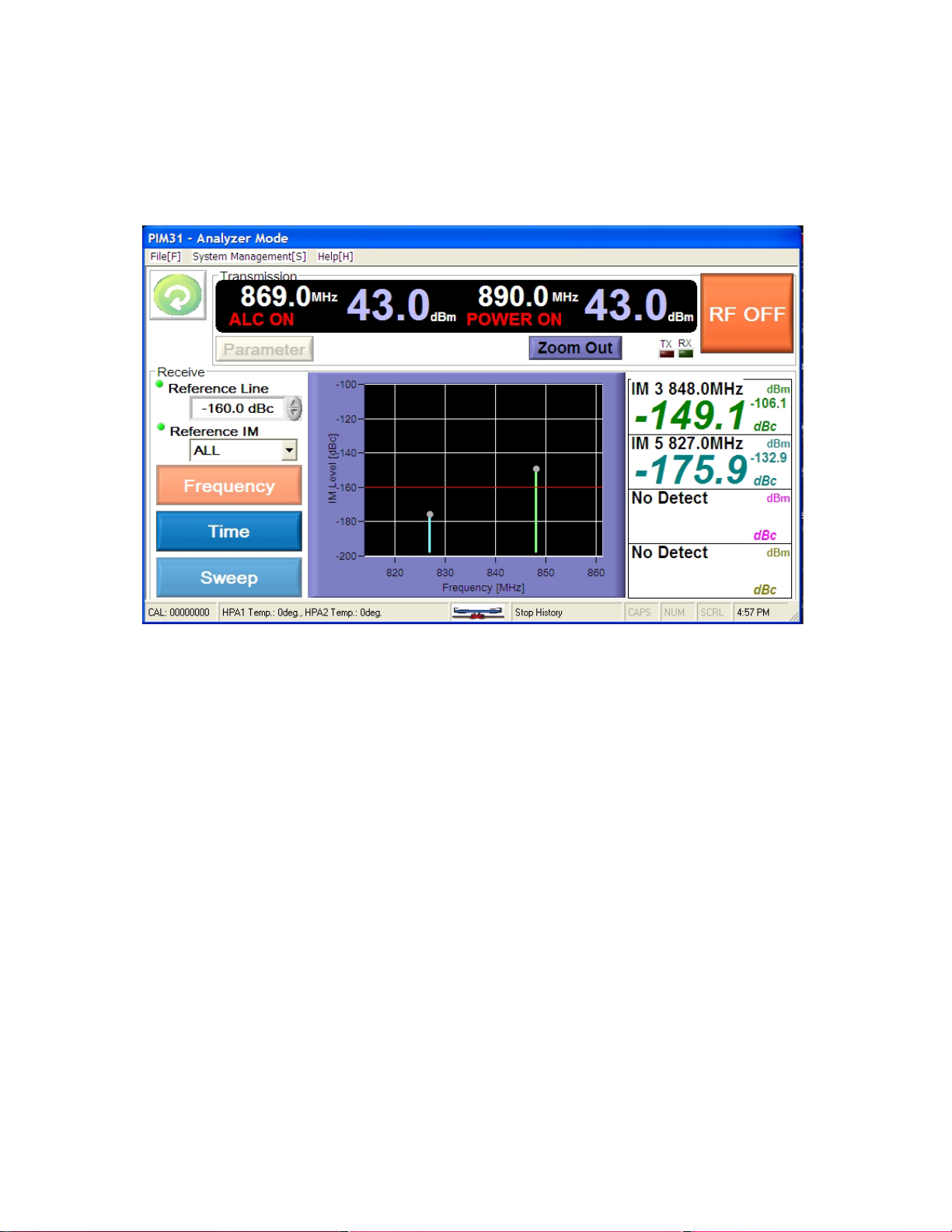
7.4.2 Time Mode
In Time mode IM products are displayed as a horizontally moving line, where the
position indicates the power level over the time. This display is very helpful to test
immediate PIM variations, like loose connections. Any change is immediately
visible. Time mode shows a 10 seconds window, but more information up to 10
minutes may be recorded. Move past traces to the window by touching, holding
and drawing it to right until the wanted information is appears.
The screenshot shows two IM signals IM3 and IM5 With -149.0 dBc IM3 exceeds
the reference limit of -153.0 dBc. IM5 measured -176.8 dBc. Frequency
information of the IM signals is provided in the numeric displays. In this example
(M3 is 846.5 MHz and IM5 824.0 MHz.
57
Page 58
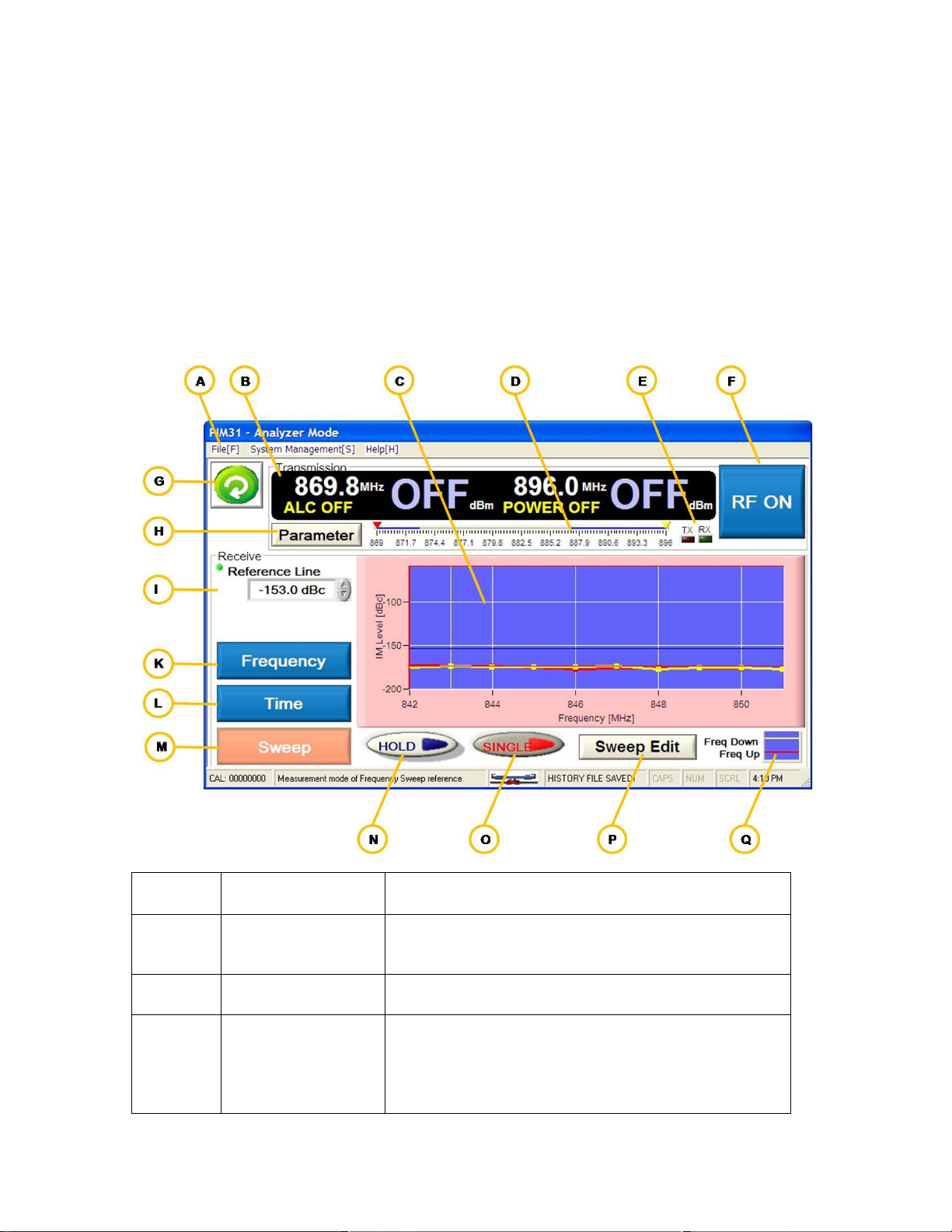
7.4.3 Sweep Mode
Element
Name
Description / Display
A
Pull-Down menu
Allows Screenshots, data logging, and self test. For
menus”.
B
Carrier display
Carrier signal information: Frequencies, Power
levels
C
Graphical display
Shows two traces (red / yellow) of an IM product
b) sweeping highest frequency carrier signal
IM products in linear environment are frequency independent. Many passive
components show a frequency response that is less linear or strongly frequency
dependent. The sweep mode increments / decrements carrier signals by 1 MHz.
covering a Tx range that results in a sweep of the complete Rx frequency range.
Any deviations of PIM measurements that are frequency dependent are
immediately visible.
more information refer to chapter “Pull-Down
that are generated by
a) sweeping the lowest frequency upwards – red
trace and after that
58
Page 59

downwards –yellow trace.
Increments are 1 MHz
screen and drawing it to the desired location
D
TX Range
Shows Range of up-sweep and down-sweep..
E
Tx/Rx
Shows internal communication activity to modules.
F
RF Power Button
Switches RF Power ON / OFF
power ON.
G
Return
Brings PM 31 back to Field Mode. Works only
when RF Power is OFF
H
Parameter Setting
To set power levels for the sweep cycles:
(P) sets frequency ranges.
I
Reference Line
Moves reference line for audible indication of
Range -60 to -200 dBc
K
Frequency
Graphic Display Frequency mode: IM signals
frequency. Signal colors relate to numeric display
L
Time
Graphic display – Time Mode: IM signals shown as
over time. Signal color relates to numeric display
M
Sweep
Graphic display Sweep mode. Signals are “swept”
over a range to test wide frequency range
N
Hold
Hold Off blue, On red. While sweeping,
measurement can be held immediately.
O
Single
Single Off –Blue, On -red. Determines if a single
sweep or continuous sweeps are measured.
P
100ms, range 10ms to 2000ms)
Q
Freq Up/Down
Only for visualization of Tx sweep ranges
IM signals as a vertical bar. Position on the x-axis
indicates frequency and length indicates power
level. Color of the bars refers to the colors of the
numeric displays (N-Q).
The graphical display is floating, meaning the
center area can be moved for better convenience
and visibility of important display information.
Moving by touching grid part of the display and the
The Button inscription shows what happens if the
button is pushed. In the shown screenshot RF
power is OFF, the next button push will switch RF
Menu comes up only with RF Power OFF
Note: frequency setting in the parameter menu is
not relevant for sweep measurements. Sweep Edit
Sweep Edit
measurements that exceed the limit. Same as
Green/Red threshold of Bar graph in field mode.
shown as vertical bar, indicating power and
moving horizontal line, indicating power (changes)
Opens Sweep Edit menu, allowing to set:
End of Lower Tx range, Start of Higher Tx range,
Selection of measured IM (in case more than one
are in the range), sweep increment time (default
59
Page 60

Element
Name
Description / Display
A
Reference IM
Allows selection of IM product (in case more than
one are in the swept range)
B
generate
C
Freq 2 Sweep
Start frequency of down-sweep
generate
D
Sweep Cycle
Time between setting and measurement of
increments
E
Set
Stores settings and returns to Analyzer Sweep
Mode
Freq 1 Sweep
Start Frequency of up-sweep
Default: lowest Tx frequency the tester can
Default: lowest Tx frequency the tester can
Note: Sweep mode requires setting the power levels (Parameter
button) and also to define the sweep frequency range (Sweep Edit
Button).
60
Page 61

8 Pull Down Menus
Field
Mode
Analyzer
Mode
File
Start History Save
X
Stop History Save
X
X X
System Management
Self Test
X
X
PIMD management
X
Connection check *
Help
Contact information
X
X
Pull down Menus offer additional features and allow users to set some system
parameters. They allow also performing a self test of the PIM31 test system.
Three Pull-Down menus are available:
• File
o Start History Save
o Stop History Save
o Screen Capture
o Initialize Program
o Quit
• System Management
o Self Test
o PIMD management
o Connection check *
Field Mode offers a subset of Pull-Down menus, Analyzer mode offers all of
them. The features available in field mode
Screen Capture
Initialize Program
Quit
X
X
*Connection check is for factory use only.
61
Page 62

8.1 File
8.1.1 Start / Stop History Save
This feature allows users to log measurements over a period of time in Analyzer
mode. The log files are stored in TSV (Tab Separated Value) ASCII text format.
Values listed are:
Date, Time, Carrier1 (MHz), Carrier2 (MHz), Output Level1 (dBm), Output Level2
(dBm), Offset (dB), ALC On/Off, Screen Mode, IM Number (Order), IM
Frequency (MHz), IM Measure(dBc), Direction, Measure Mode/Pass IM
Level/decision
Note: PIM 31 does not support Offset, Measure Mode/Pass and IM
Level/decision. This are reserved for other test systems. The log data will show a
hyphen “-“in these columns. Direction is always reverse for PIM31 test systems.
Each log cycle requires manual start, entering a file name, and manual stop. File
name directory and drive can be chosen at liberty.
62
Page 63

8.1.2 Screen Capture / Print
This menu provides capabilities to capture a screen shot from any Graphical
Display of the Analyzer Mode. Capturing a screen shot requires manual trigger,
entering a file name, drive and directory. By default, the file name consist s of
date and time, but can be modified by the user. The file is stored in jpeg format
by pressing the blue save button. The stored file has a size of about 150kB. In
addition to the graphic display and IM related information the scr ee n capt ure
procedure allows the user to enter equipment information and a serial number for
the DUT.
Note: Only the graphic display and relevant information is stored with
the screen shot. Active measurements will be stopped during the
screen capture process.
63
Page 64

8.1.3 Initialize Program
8.1.4 Quit
Initialize should only be
triggered if the system shows
signs of irregular function. It
sets system values to default
values, manual settings may
be lost.
Quit has the same functionality as Exit in the Field Mode. The user will be asked
if he really wants to quit the PIM 31. If answered YES, the system will power
down. Quit works only with RF power OFF
64
Page 65
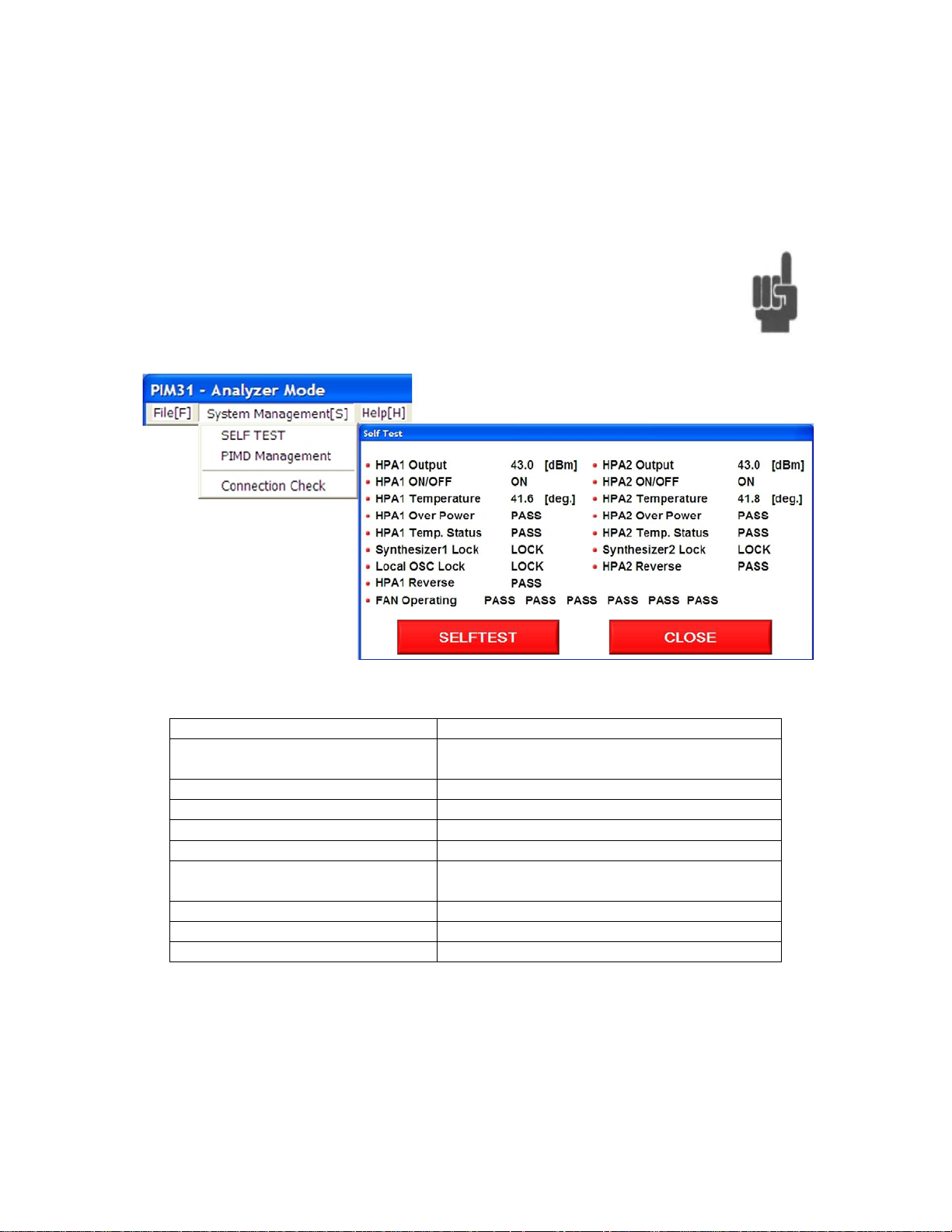
8.2 System Management
Name
Description
HPAx Output
RF Output power level (should be +/- 0.2
db within the set limits – ALC ON)
HPAx ON/OFF
Status of RF Power (ON/OFF)
HPAx Temperature
Temperature of amplifiers.
HPAx Over Power
Reverse Power
HPAx Temp Status
On Fail (too hot), System will shut down
locked
HPAx Reverse
Reverse PIM measurement blocks status
Local Osc Lock
Local Oscillator functionality
Fan Operating
Operation status of 6 fans
8.2.1 Self Check
Self check provides information about the PIM 31 test system. To
allow the self check routine to test all modules, it needs to be
performed with RF Power ON
Synthesizerx Lock
Synthesizers of Transmitter and Receiver
65
Page 66

8.2.2 PIMD Management
Name
Description
Equipment Selection
Not relevant for PIM31, since these
provide only one frequency band.
Filter Bandwidth
Default 1.2 kHz
“System Menu”.
IM Level Sound
If ON, sound occurs when PIM level
exceeds reference line.
SET
Stores settings
CLOSE
Returns To Analyzer Mode
PIMD management allows setting some system and measurement
parameters. With the exception of Sound On /Off, it is not required to
change these settings.
For further information refer to chapter
66
Page 67

9 Remote Application and TCP/ IP Setup
PIM31 Remote Control Panel is the software to control the PIM31 unit from any
PC using a TCP/IP cable connection. This section explains how to setup the
PIM31 unit for TCP/IP from any PC and also the use of the remote application.
The software can be downloaded from the Boonton official website under
Products “Manuals & Software”.
9.1 Installation and connection setup for remote control:
9.1.1 Install PIM31 Remote Software
• Download the PIM31 Remote Control software from Boonton’s official
website under product’s “Manuals & Software” section
• Follow screen instructions during the installation process
• Click on “Remote_ctr_V1.2.exe” icon from PC’s desktop to open the
software.
9.1.2 Known issues that might occur during installation on Windows OS:
Error message as “Component MSWINSCK.OCX or one of its
dependencies not correctly registered: a file missing or invalid”.
If you do not see this message continue with 9.1.3
Solution:
• Search internet or oth e r comput ers for the missing windows system
file “MSWINSCK.OCX”,
• Download and save that file into your PC under any folder
• Copy the file into Windows System32 folder
C:/Windows/System32/
• Click the executable file “Remote_ctr_V1.2.exe” again
9.1.3 Setting IP address of PIM31
• Go to the “Control Panel” of the PIM31’s desktop screen and open the
“Network Connections” icon.
67
Page 68

• Right click the “Local Area Connection” icon and open the properties
window.
• Select the “Internet Protocol (TCP/IP)” from the list and enter the IP
address in input field.
• Check “Use the following IP address”
• Enter IP Address: 192.168.0.10 (for example)
(The last number can be any number between 0 and 254 but should be
higher than that of the PC’s IP address)
• Subnet Mask: 255.255.255.0
• Press OK button when done
9.1.4 Connecting PIM31 and PC.
Connect the PIM31 unit to a PC with a regular LAN cable (not crossed type).
9.1.5 Setting IP Address of PC
• Go to “Control Panel”, find & open the “Network Connections” icon.
• Right click the “Local Area Connection” and open t he properties window.
• Select the “Internet Protocol (TCP/IP)” from the list and enter the IP
address in input field.
68
Page 69

• Enter IP Address: 192.168.0.1 (for example)
(the last number should be lower than the same of PIM31 IP address)
• Enter Subnet Mask: 255.255.255.0
• Gateway: (Leave it as blank because it does not affect the operation)
9.1.6 Check the network connection status of PIM31 and PC
The network connection status for both PIM31 and the PC can be verified by
following as below:
a. Tray icon on the status bar.
b. Check the normal status with clicking the network icon.
Note: Connecting PIM31 and PC will disconnect Wireless link of the PC.
69
Page 70

9.2 Using PIM31 Remote Application:
Before using the remote application the following default settings for both
IP address and port nu mber need to be verified.
9.2.1 Enter IP address and Port
• Open the “PIM31 Remote Control” software from desktop
• Verify that the IP Address is same as PIM31:
Default : 192.168.0.10
• Enter Port 3100
• Press”Connect” button.
The “Equipment Get” buttons is now enabled
• With proper connection PIM31 should now show “Remote Control” on
its screen
• Press “Equipment Get” button.
The model is now shown in the Eq uipment field and the settings of
equipment are shown as well.
• Change settings by overwriting the relevant fields and push “Set” button.
• Pressing “RF ON” activates the RF and measurements are done
automatically.
• “RSSI” can be pushed while RF is off
70
Page 71

9.2.2 List of remote commands
Below are the lists of remote commands which can be executed remotely either
by using Telnet or HyperTerminal with a regular type of LAN cable connection
to the PIM31 unit. It is recommended to add “\r\n” at the end of each remote
command if proprietary applications to execute the following commands are
used. This avoids problems to complete the command executions.
Command Parameter Return value Unit Description
*IDN? Product, Model
*RST
F1
F2
P1
P2
SET
GET
ALC
BW index 1,0 1:True , 0:False
RF
STAtus
F1 Frequency MHz
F2 Frequency MHz
P1 Power dBm
P2 Power dBm
ALC
BW
RF
ERRor
PIM
RSSI
Frequency
Frequency
Power
Power
ON, 1
OFF,0
ON, 1 1,0 1:True , 0:False
OFF,0 1,0 1:True , 0:False
1,0
1,0
1,0
1,0
1,0
1,0
F1,F2,P1,P2,
ALC,BW,RF
1,0
index
1,0
Last Error
PIM, Order,
IM Frequency
RSSI
MHz
MHz
dBm
dBm
1:True , 0:False(Out of Range)
1:True , 0:False(Out of Range)
1:True , 0:False(Out of Range)
1:True , 0:False(Out of Range)
1:True , 0:False
1:True , 0:False
Error Log of Last command
71
Page 72

10 PIM31 Repor ter Software
PIM31 Data Manager creates report fil es in a PDF format . T his so f t ware allows to
conveniently generating report files after collecting measurement data from a
multitude of base stations and locations. This applicati on can be downloaded
from Boonton’s official website under product’s “Manuals & Software” section.
Note: To be processed, PIM31 log data has to be stored on a USB memory stick
connected to one of the PC’s USB ports.
10.1 Installation
• During installation the user need to select the option to include PDF
creator software which comes free with this installation file.
72
Page 73

• Check the box during installation progress for PDF creator as below
10.2 PIM 31 Reporter settings
• Copy the log file from the PIM31 unit by using any USB memory stick and
transfer them into the PC by creating any folder
• Select the “Load Data” button from the PIM31 Data Management
Software in order to open the collected log file.
73
Page 74

• Open the collected log file name from the folder location of your PC.
• File Menu “PDF File Name” allows selecting desired naming conventions
for the PDF report file.
74
Page 75

• Select the measurement(s) you want to have as PDF report by checking
the appropriate box (es).
• “Store PDF” creates and stores a PDF report file. It c an be saved at any
folder location of your PC.
The example on the next page shows a typical report file.
75
Page 76
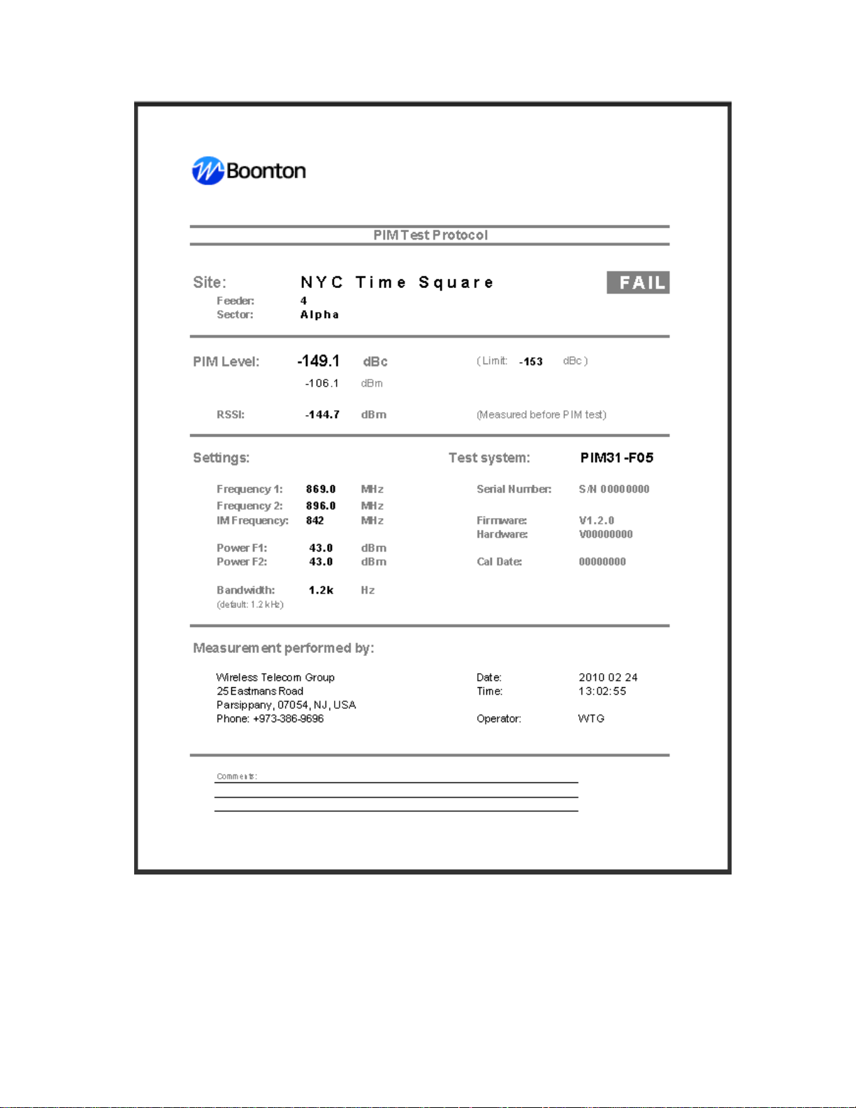
76
Page 77

11 What is PIM?
PIM distortion is caused by non-linear mixing of two or more frequencies in
passive devices like cables and connectors. Ideal passive devices are
considered linear. In reality any linear component has a non-linear factor that can
cause PIM distortion. For optimal operation of RF systems, PIM has to be kept at
a very low level that has virtually no influence on the network operation. PIM
signals are generally unwanted because they can interfere with si gnals in a
receive path.
11.1 What Causes PIM?
Passive intermodulation can be caused by a variety of factors. PIM distortion is
often the result of flaws in component design and manufacturing processes. PIM
distortion may also be caused by wear and tear on components due to
mechanical constraints or environmental conditions.
11.1.1 Manufacturing & Design
• Use of ferromagnetic materials, such as nickel or steel, within the current
path. Especially at higher power levels, PIM can be generated due to
hysteresis effect of these materials and the non-linear voltage to current
ratio.
• Contaminations, like particles from machining operations or soldering
splatters that touch current carrying surfaces.
• Separation of current carrying contact zones through irregular contact
surfaces, corrosion and insufficient contact pressure.
• Dissimilar metals at contact areas.
• Insufficient thickness of plated metal causing RF heating through the skin
effect of RF.
• Bad solder joints.
11.1.2 Mechanical
• Poor mechanical alig nmen t of co mponents
• Too much or too little torque at connections
• Contaminated connectors
77
Page 78

11.1.3 Environment
• Daily temperature variations, thermal loading by the sun and RF heating
vary junctions and can cause, often intermittent, PIM distortions.
• Wind-induced vibrations vary junctions, and can weaken or break down
joints.
• Airborne dirt and moisture cause oxidation of materials and cause PIM
distortion.
The antenna in the picture shows
oxidation within the power divider.
Tests with vector analyzer line
sweep test would not reveal the
problem; however PIM testing
detected the issue immediately
11.2 How to test PIM
PIM testing for field appli ca ti ons req ui r es the i nj ect ion of two CW signals (f1 and
f2) into a system under test. Intermodulation products (IM) of the 3rd, 5th, 7th…
order, caused by faulty components, appear immediately. The strongest
intermodulation product is usually that of the 3rd order (IM3). Frequencies of
these intermodulatio n pr oduct s can be calculated as follows:
f
= (2 x f1) – f2
IM3L
f
= (2 x f2) – f1
IM3H
The picture below shows an example of passive intermodulation. Frequencies f1
(869 MHz) and f2 (894 MHz) are located in the Tx range, causing intermodulation
fIM3L (844 MHz) and fIM3H (919 MHz). Both IM products can cause serious
interference.
78
Page 79
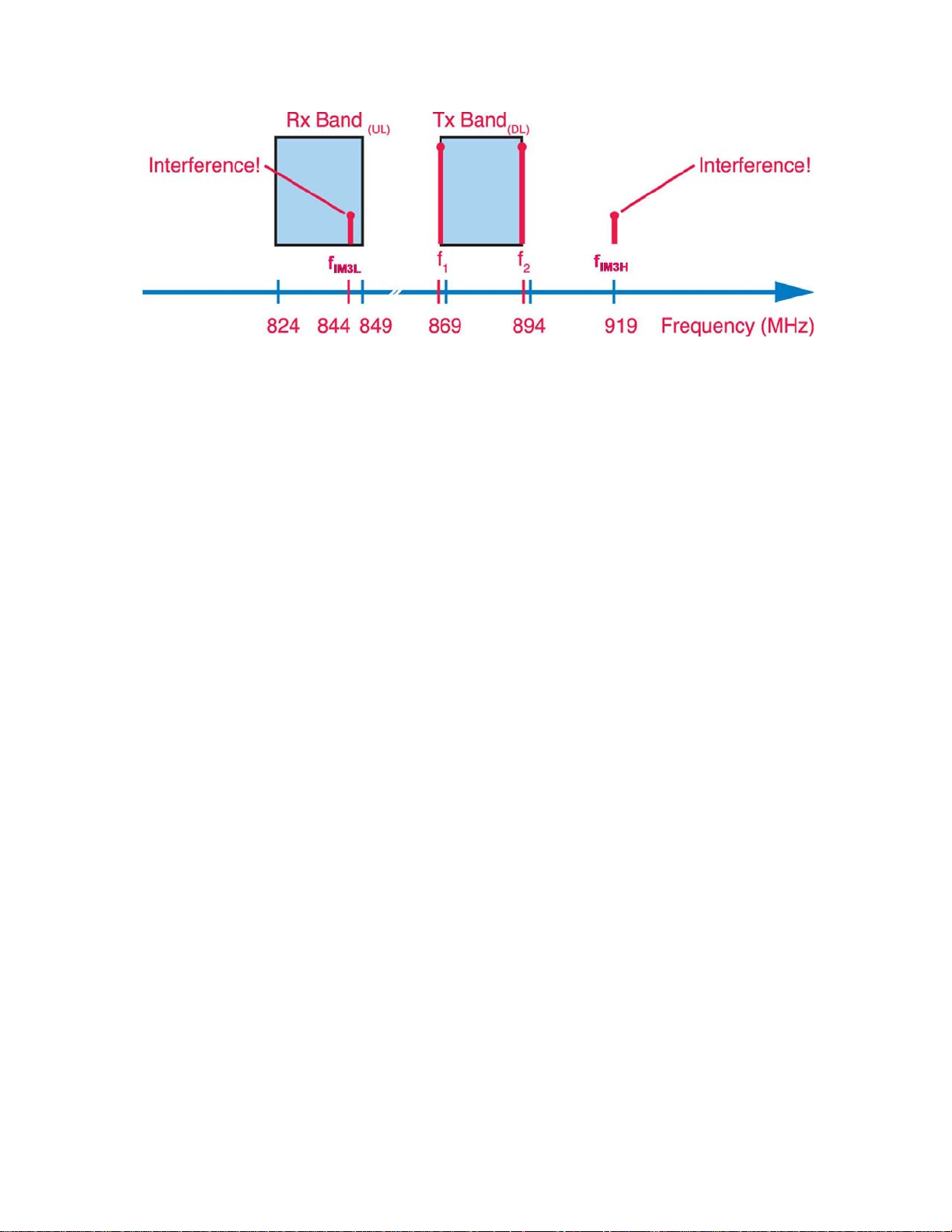
A visual example of intermodulation caused by two CW signals. Ideally, test
frequencies f1 and f2 should be at the edge of the transmit guard bands, so that
the IM3 products f
IM3L
and f
fall at the edge of the receive band(s), usually
IM3H
utilized as guard bands. This minimizes interference within the system under test
and also eliminates potential interference in other wireless bands
IM3 serves as an example. With IM3 as a result of PIM, other IM products (IM5,
IM7, IM9, IM11, …) will be present as well, and can impact base station
performance significantly.
79
Page 80

12 PIM 31 Technic al Inform a t ion
12.1 Tester Types
PIM 31 Type Tx Band Rx Band Technology
F01 869-896 MHz 824-851 MHz CDMA (850)
F02 925-960 MHz 880-915 MHz E-GSM (900)
F03 1805-1880 MHz 1710-1785 MHz DCS (1800)
F04 1930-1990 MHz 1850-1910 MHz PCS (1900)
F05 2110-2170 MHz 1920-2060 MHz
F06 935-960 MHz 890-915 MHz GSM (900)
F07U 730-759 MHz 776-788 MHz LTE-US (700-U)
F07L 730-759 MHz 701-716 MHz LTE-US (700-L)
F07UL 730-759 MHz
F08 2010-2025 MHz 1900-1920 MHz TD-SCDMA (2000)
F09 2010-2155 MHz 1710-1755 MHz AWS
F10 2620-2690 MHz 2500-2570 MHz IMT-E (2600)
776-788 MHz
701-716 MHz
UMTS/WCDMA
(2100)
LTE-US (700_UL)
80
Page 81

12.2 Specifications (Data Sheet)
12.2.1 Transmitter Specification
Carrier Power Adjustable Level +20 to + 44 dBm
Carrier Power Resolution / Accuracy 0.25 dB / ±0.35 dB
Frequency Range see version table
Frequency Increment 200 kHz
Frequency Accuracy (typical) 2 ppm
Frequency Tuning Lock Time (typical) 1 ms
Reverse Power Protection 43 dBm / 5 sec
(Include ON/OFF Func ti on)
12.2.2 Receiver Specifications
Reverse IM -132 dBm / -175 dBc
Accuracy ±0.35 dB
Average Noise Floor -138 dBm (1.2 k filter)
Dynamic Range (typical) 96 dB
(reference -90 dBm)
Measurement Interval 100 to 350 ms
Effective IF Bandwidth 300, 600, 1.2k, 2.4k,
(Operator selectable) 5k, 10k, 12k, 15k, 25k
50kHz
Operational Input Power - 45 dBm RMS
Input Power without damage - 10 dBm max
Warm-Up Time for specified acc ur acy 5 minutes
12.2.3 System Specifications
RF Connector DIN 7-16
(3) USB ports
VGA output
REF Out 10MHz
User Interface Display 7” TFT with touch screen display
IM Measurement Alarms Audio / visual
Operating Voltage 90 to 264 V (50-60 Hz)
Power requirements 750 VA max
81
Page 82

12.2.4 Environmental
Operating Temperature 0° to 40°C
32° to 104°F
Humidity (non-condensing) 85% RH
Max Altitude 2000 Meters / 6560 ft
12.2.5 Dimensions and Weight
All types except F02 and F07UL
Dimensions (W/D/H) 396 x 521 x 236 (mm)
15.6 x 20.5 x 9.3 (in)
Weight: 23.8 kg / 52.3 lb
F02
Dimensions (W/D/H) 396 x 602 x 236 (mm)
15.6 x 23.7 x 9.3 (in)
Weight (P IM31-F02) 25.3 kg / 55.7 lb
F07UL
Dimensions (W/D/H) 396 x 602 x 274 (mm)
15.6 x 23.7 x 10.8 (in)
Weight 31.2 kg / 68.5 lb
82
Page 83

13 Maintenance
13.1 Block Diagram
83
Page 84

13.2 Performance Check
To maintain maximum performance, it is highly recommended to conduct a basic
test of the PIM31 on a daily basis.
The following components ar e req uir ed for th e perf or mance test :
• Low-IM Termination Load (Boonton 50 W Low PIM Load)
• Low PIM Cable
Install the test set-up as shown:
13.2.1 Testing Analyzer operation status
• Connect the Low PIM Load to a PIM 31 test system with torque wrench
• Set PIM 31 to Analyzer Mode
• Set the frequencies o f carr i er sig nal s 1 and 2.
• Set the power levels to 43 dBm (20W) – with ALC: ON
84
Page 85

• Switch RF Power ON
• The PIM Signal(s) should be at a level below -160 dBc .
If the reading is higher (lower negative value), switch RF OFF, disconnect
connections and re-connect them.
Repeat test
If the reading is still above -160dBc replace low PIM cable and retest.
Hint: Low PIM cables wear out with use. If a cable does not
longer perform in the desired way, dispose of it and replace it
with a new cable. Worn out cables can cause unnecessary work
and costs. Trying to repair a base station with a worn out cable
will lead to no avail.
• Switch “RF Power OFF
• Set the PIM 31 to Field Mode
• Since the PIM 31 test system is connected to a low PIM load (not to an
active antenna), the RSSI value shows the noise floor of the instrument.
• RSSI should
be below -130dBm
85
Page 86

13.3 Performance Verification
Performance Verification measures output signals and frequency accuracy /
selectivity of the PIM31.
13.3.1 Tx Signal Power Level
The following components ar e required for the performance verification.
• 50W Low-PIM Termination Load (Boonton 95960501A)
• Low PIM Cable (Boonton: 95960401A)
• High Power coupler 30dB coupling (with known linearity)
• RF Power Meter (Boonton 4540 w/ Sensor 51071A)
Install the test set-up as shown:
86
Page 87

• Connect the Coupler, Low PIM Load a nd Po wer Meter to the PIM 31 test
system (use torque wrench)
• Set the PIM 31 to Analyzer Mode
• Set frequencies of carrier signals 1 and 2 to the start and end frequency of
the provided frequency band.
• Set the power level of each signal to 40 dBm (20W) – with ALC: ON
• Switch RF Power ON
• With offset compensation of the coupler (30dB) the power meter should
read 43dBm +/- 1.0dB
If the reading deviates, switch RF power OFF, disconnect connections,
reconnect and repeat the test.
If the reading is off by more than 1 dBm, the deviation could be caused
by an malfunctioning attenuator or amplifier in the PIM 31 Test System.
In this case, contact your nearest Boonton Service Center .
With the reading within limits, continue procedure:
• Increase Signal Levels by 1dB,
• Measure power
• Repeat until Signal Levels are both at 43dBm.
• With offset compensation of the coupler (30dB) the power meter should
read now: 46dBm +/- 1.0dB
.
• Switch “RF Power OFF
87
Page 88

13.3.2 Tx Signal Frequency
In order to measure the accuracy of carrier frequencies, use the foll owing
components and equipment.
• Spectrum Analyz er
• High power coupler 30 dB
• 50W Low PIM Load
Install the test set-up as shown:
88
Page 89

• Connect the Coupler, Low PIM Load a nd Sp ect r um Analyzer to the PIM
31 test system (use torque wrench)
• Set Spectrum Analyzer to proper measurement range
• Set the PIM 31 to Analyzer Mode
• Set the frequencies o f carr i er sig nal s 1 and 2 to the start and end
frequency of the provided frequency band.
• Set the power level of each signal to 40 dBm (20W) – with ALC: ON
• Switch RF Power ON
• Spectrum analyzer should show both PIM 31 frequencies with +/-200 kHz
accuracy.
If the reading deviates, switch RF power OFF, disconnect connections,
reconnect and repeat the test.
If the reading is off by more than 200 kHz, it may be an indication that
the synthesizer module is malfunctioning. In this case, contact your
nearest Boonton Service Center .
With the reading in limits, continue procedure:
• Increase on F1 Signal frequency by 1MHz
• Measure both frequen ci es
• Repeat the process you are no longer able to increase the signal
frequency F1
• If done, set F1 back to start frequency
• Decrease F2 by 1 MHz
• Measure both frequen ci es
• Repeat the process you are no longer able to decrease the signal
frequency F2
• Switch “RF Power OFF
89
Page 90

13.3.1 Rx Power and Receiving Frequency
The following measurements have to be executed with
utmost care:
If too much power is applied to the PIM31 test system, the
receiver module will be damaged
If the RF output power of the PIM31 is accidentally switched
ON, it . will damage the Signal Generator .
In order to measure the accuracy and frequency selectivity of the receiver, the
following components and
• Signal Generator
Install the test set-up as shown:
• Set the PIM31 to Field Mode
• Set frequencies of carrier signal 1 and 2 to the start and end frequency of
the provided frequency band.
• Set the power level of each signal to 20 dBm (100mW) – with ALC: ON
• Set the Filter bandwidth of the PIM31 to 1.2 kHz (default).
• To avoid damage, RF Power of the PIM 31 must be OFF
90
Page 91

• Set Signal Generator to IM3 frequency.
• Apply signal to PIM 31 (-60dBm to -120dBm)
• RSSI should measure the applied power
• If the reading is off by more than +/- 0.5 dB but not worse than
+/-15 dB, it may be an indication that receiver is out of
calibration. If the measurement shows a level lower than
-125dBm, the receiver does not detect the frequency at all. It
may be asynchronous. In the cases described above, contact
your nearest Boonto n Ser vice Center .
With the reading in limits, continue procedure:
• Change the frequency of the RF Generator by 2.5 kHz.
• The receiver will filter the signal out and the RSSI reading of PIM31
should be lower than -125dBm.
With the reading in limits, continue procedure:
• Increase the PIM 31 Signal frequency F1 by 1 MHz
• Set Signal Generator to the frequency that correlates to the IM3 product of
frequencies F1 and F2
• Read the RSSI on PIM31; the value should be equal to +/-1 dB of Signal
Generator’s Power level
• Repeat the process you are no longer able to increase the signal
frequency F1 due to band restrictions
• If done, set F1 back to start frequency
• Decrease PIM31 Signal frequency F2 by 1 MHz
• Set Signal Generator to Frequency that results for IM3 product of
.
frequencies F1 and F2
91
Page 92

• Read RSSI on PIM31; value should be +/-1 dB of to Signal Generator’s
Power level
• Repeat the process you are no longer able to decrease the signal
frequency F2
• Set PIM 31 Signal frequencies F1 and F2 back to Start and End
frequencies of PIM31 band.
• Set Signal Generator to Frequency that results for IM3 product of
frequencies F1 and F2
• Read the RSSI value on PIM31; the value should be equal to +/-1 dB of
the Signal Generator’s Power level .
• Change the power level of the Signal Generator by 5dB.
Never exceed -60dBm
• Read RSSI on PIM31; value should be equal to +/-1 dB of the Signal
Generator’s Power level .
.
• Repeat until power level range of -60dBm to -120dBm has been covered
• Switch RF Signal of Signal Generator OFF
If the readings from the previously listed procedures deviate by more than
+/- 1 dB, contact your nearest Boonton Service Center .
92
Page 93

14 Accessories
Test Cable for 20W PIM tester 3m (10ft) - Low PIM,
95960401A
Load 50W - Low PIM, DIN7/16 (m) - DIN7/16(f)
95960501A
PIM Source for 20W PIM tester - through technology
95960601A
Connector Saver DIN7/16(m)-DIN7/16(f)
95951101A
Adaptor 7/16 (f) - 7/16 (f), low PIM
95950301A
Adaptor 7/16 (f) - N (m), low PIM
95950401A
VZW Torque Wrench 18lbs
95951001A
PIM Source for 20W PIM tester - through technology
95960601A
Transit Case 1 for PIM31 with standard size body, holds also
95960701A
Transit Case 2 for PIM31 with extended size body, (e.g. F02
95960801A
Accessory Bag
70047300A
Roll-up Keyboard (USB)
48401100A
USB Mouse
48401200A
DIN7/16(m)-DIN7/16(m)
(requires termination load)
(requires termination load)
accessories & cable
& F07UL) holds also cable
93
Page 94

Appendix A
Warranty Statement
Boonton Electronics warrants the PIM 31to the original Purchaser to be free from
defects in material and workmanship and to operate within applicable
specifications for a period of two years from date of shipment. Test cable(s) and
connector savers are not covered under warranty. Boonton Electronics further
warrants that its instruments will perform within all current specifications under
normal use and service for two years from date of shipment. These warranties do
not cover sealed assemblies which have been opened, or any item which has
been repaired or altered without Boonton’s authorization. Boonton’s warranties
are limited to either the repair or replacement, at Boonton’s option, of any product
found to be defective under the terms of these warranties. There will be no
charge for parts and labor during the warranty period. The Purchaser shall
prepay inbound shipping charges to Boonton or its designated service facility and
shall return the product in its original or an equivalent shipping container.
Boonton or its designated service facility shall pay shipping charges to return the
product to the Purchaser for domestic shipping addresses. For addresses
outside the United States, the Purchaser is responsible for prepaying all shipping
charges, duties and taxes (both inbound and out b oun d) .
At Boonton's option, an extended Warranty period may be available for an
additional charge. Please contact one of our sales offices for further information.
If an extended warranty option has been purchased, the extended period is
substituted for the 2 year period above. Note that the extended warranty does not
extend the instrument's calibration interval past 12 months. The instrument must
be maintained in a calibrated (instrument having received calibration or
verification at recommended interval) state throughout the warranty period to be
eligible for warranty service to remedy "out of spec" operation.
94
Page 95

Instrument Verification Definition:
Instrument verification is comprised of the following:
Inspection: Each unit is inspected for damage and wear and tear. Key
functions are checked. The inspection is carried out both
external and internally. Any damaged or malfunction is noted
on the service report, providing the user with an overview of
the equipment’s status .
Maintenance: Units sent in for verification undergo a standard maintenance
procedure. The instrument is cleaned of dust and marks on
both the inside and outside. Most Boonton testers have EMI
protection cover and screen can impair visibility. Fans and
filters are cleaned to enhance cooling and the device’s
lifespan.
Verification: All specified values which can deviate over time are checked.
This includes all paths a signal can take for m easur ement.
Instrument Calibration Definition:
Instrument calibration is comprised of Instrument Verification PLUS the following:
Alignment: If equipment has drifted out of verification limits then the
instrument will be aligned. Alignment tunes the unit into the
center of these verification limits. This results in maximum
measurement precision. Only Boonton, as manuf actur er has
the competence necessary to provide such alignment.
Documentation: Together with the calibrated instrument the user receives
documents which certify and describe the status of this
instrument. The Calibration Certification declares the
conformity of the unit with published specifications. A
Calibration Report shows all test points with rated value,
verification limit and measurement uncertainty. The service
report provides the user with status of his instrument.
95
Page 96

Appendix B
EC Declaration of Conformity
EC DECLARATION OF CONFORMITY
25 Eastmans Road
Parsippany, NJ 07054 USA
Manufacturer: Boonton Electronics
Equipment Type: PASSIVE INTERMODULATION ANALYZER
Model No(s): PIM 31
Boonton Electronics hereby declares that the above described
product(s) conforms to European community (EC) Council Directiv es
89/336/EEC//93/68/EEC and Standards: Test Cert Number CPS
A0136869
Issue Date: 04/15/10
Issue Place: Parsippany, NJ, USA
Dom A Lauria
Quality Assurance Manager
96
Page 97

Appendix C
Special Units Packing List
PIM31-F01 S/1 1 Instrument 869-896 MHz
99770102A 1 Base Instrument PIM31-F01
48401100A 1 Roll-up Keyboard
48401200A 1 USB Mouse
95951101A 1 Connector Saver
56810400A 1 Power Cord
98906200A 1 PIM31 Manual
PIM31-F04 S/1 1 Instrument
99770402A 1 Base Instrument PIM31-F01
48401100A 1 Roll-up Keyboard
48401200A 1 USB Mouse
95951101A 1 Connector Saver
56810400A 1 Power Cord
98906200A 1 PIM31 Manual
PIM31 Accessory Kit S/1
95960701A 1 PIM 31 Transit Case
95960501A 1 50W Low PIM Load
95960601A 1 PIM Source 20 W through
95960401A 1 Test Cable 3M 7/16M-7/16M
95951001A 1 Torque Wrench 18 Ft/lbs
95951101A 2 Connector Saver
95950301A 1 Adaptor 7/16 (f) - 7/16 (f), low PIM
95950401A 1 Adaptor 7/16 (f) – N (m), low PIM
95951401A 1 Adaptor 7 /16 (f) – N (f), low PIM
97
Page 98

Appendix D
Number
Element
Description
1
Power Switch
Functions similar to a PC:
must be in ON position.
PIM31-F07-UL Operation
This section describes the operation and functionalities of the PIM31-F07-UL PIM
Analyzer which are relevant to this particular model only. All other information
regarding safety and precautions are identical to other PIM31 models, and are
described in chapter 2 of this instruction manual. The unit has a single, Analyzer
mode of operation, displaying frequency, time and sweep functions.
PIM31-F07-UL Front Panel
One short push – PIM31 powers up.
Another short push – controlled power
down.
Holding for 3 seconds – powers unit
down immediately.
See also chapter Powering PIM31
up/down.
Note: Main Power Switch on the back
98
Page 99

2
USB Ports (3)
USB ports for mouse, keyboar d and
memory stick.
3
LAN connector
For factory use only.
4
RF Port w/ protection
cap
RF Port.
is not in use.
5
Audio
Loudspeaker for audio si g nal s .
6
Touch Screen
Touch screen display 800x600.
on the screen.
7
RF Power On
RF power light indicates when RF Power
is present.
8
Type Label
Provides information about PIM31 Tx/Rx
frequency bands.
9
Front Panel Air
Always allow for proper airflow, and
sucked in.
Always use protection cap when PIM31
Display
Vents
PIM31-F07-UL Back Panel
Never use sharp objects to push buttons
prevent alien objects or dust from bei ng
99
Page 100

Number
Element
Description
1
Main Power supply
AC Supply: 90-264V, 7 50W / 750VA
use 90 deg connector only.
Fuse: 4A / 230V or 8A / 110V.
2
Main Power Switch
PIM31 contains protection circuitry to control
Power Button to power the system down.
3
10 MHz Reference
out
10 MHz reference output to synchronize
external equipment.
4
Air Flow Fan
Always ensure sufficient air flow.
5
Air Flow Fan
Always ensure sufficient air flow.
RF power during operation and during power
on/off cycles.
After switching Main Power Switch on, wait 2
seconds before pushing Front Power Button.
Fans may briefly run after power off.
Note: Do not use Main Power Switch while
system is in operation mode as vital files
may be corrupted. Always use the Front
Getting Started
(1) Powering Up:
PIM 31 test systems power up in a similar fashion to a desktop PC. However,
there is one exception: Significant RF power has to be controlled and managed.
For this reason, PIM 31 Series instruments contain a system to protect the
hardware and prevent unusual on / off cycles (such as 3 cycles per second).
When operated normally, the user will not be aware of these protective
measures.
• Briefly press the start button on the front panel.
100
 Loading...