

Page 1

INSTRUCTION MANUAL
4240 SERIES
RF POWER METER
REV DATE 01/19/2011
MANUAL P/N 98406700A
CD P/N 984
Wireless Telecom Group
25 EASTMANS ROAD, PARSIPPANY, NJ 07054
Telephone: 973-386-9696
Fax: 973-386-9191
Email: [email protected]
Web:
www.wtcom.com
06799A
Page 2

Boonton 4240 Series RF Power Meter
INSTRUCTION MANUAL, 4240 SERIES RF POWER METER
Revision date 01/19/2011
© Copyright in 2005-2011, by BOONTON Electronics, a subsidiary of the Wireless Telecom
Group, Inc.
Parsippany, NJ, USA. All rights reserved.
P/N 98406700A
This manual covers instrument serial numbers: 11001 and higher.
K-Connector® is a registered trademark of Anritsu Corporation.
ii
Contents
Page 3

Boonton 4240 Series RF Power Meter
SAFETY SUMMARY
The following general safety precautions must be observed during all phases of operation and maintenance
of this instrument. Failure to comply with these precautions or with specific warnings elsewhere in this
manual violates safety standards of design, manufacture, and intended use of the instrument. Boonton
Electronics assumes no liability for the customer’s failure to comply with these requirements.
THE INSTRUMENT MUST BE GROUNDED
To minimize shock hazard the instrument chassis and cabinet must be connected to an electrical ground.
The instrument is equipped with a NEMA three conductor, three prong power cable. The power cable must
either be plugged into an approved three-contact electrical outlet or used with a three-contact to a twocontact adapter with the (green) grounding wire firmly connected to an electrical ground in the power
outlet.
DO NOT OPERATE THE INSTRUMENT IN AN EXPLOSIVE ATMOSPHERE
Do not operate the instrument in the presence of flammable gases or fumes.
KEEP AWAY FROM LIVE CIRCUITS
Operating personnel must not remove instrument covers. Component replacement and internal adjustments
must be made by qualified maintenance personnel. Do not replace components with the power cable
connected. Under certain conditions dangerous voltages may exist even though the power cable was
removed, therefore; always disconnect power and discharge circuits before touching them.
DO NOT SERVICE OR ADJUST ALONE
Do not attempt internal service or adjustment unless another person, capable or rendering first aid and
resuscitation, is present.
DO NOT SUBSTITUTE PARTS OR MODIFY INSTRUMENT
Do not install substitute parts or perform any unauthorized modifications or the instrument. Return the
instrument to Boonton Electronics for repair to ensure that the safety features are maintained.
Contents
iii
Page 4

Boonton 4240 Series RF Power Meter
SAFETY SYMBOLS
This safety requirement symbol (located on the rear panel) has been adopted by the
International Electro-technical Commission, Document 66 (Central Office) 3, Paragraph
5.3, which directs that an instrument be so labeled if, for the correct use of the instrument,
it is necessary to refer to the instruction manual. In this case it is recommended that
reference be made to the instruction manual when connecting the instrument to the proper
power source. Verify that the correct fuse is installed for the power available.
The CAUTION symbol denotes a hazard. It calls attention to an operational procedure,
practice or instruction that, if not followed, could result in damage to or destruction of
part or all of the instrument and accessories. Do not proceed beyond a CAUTION symbol
until its conditions are fully understood and met.
The NOTE symbol is used to mark information which should be read. This information
can be very useful to the operating in dealing with the subject covered in this section.
The HINT symbol is used to identify additional comments which are outside of the
normal format of the manual, however can give the user additional information about the
subject.
iv
Contents
Page 5

Boonton 4240 Series RF Power Meter
1. General Information..............................................................................................1-1
1.1 Organization.......................................................................................................... 1-1
1.2 Description............................................................................................................1-2
1.3 Features................................................................................................................. 1-2
1.4 Accessories ........................................................................................................... 1-5
Standard ............................................................................................................... 1-5
Optional................................................................................................................ 1-5
Sensors ................................................................................................................. 1-5
1.5 Models, Options and Configurations .................................................................... 1-5
1.6 Specifications........................................................................................................1-6
SENSOR INPUTS ............................................................................................... 1-6
FEATURES .........................................................................................................1-6
UNCERTAINTIES .............................................................................................. 1-7
MEASUREMENT SYSTEM ..............................................................................1-7
CALIBRATION SOURCE.................................................................................. 1-7
EXTERNAL INTERFACES ............................................................................... 1-8
PHYSICAL AND ENVIRONMENTAL CHARACTERISTICS .......................1-8
OTHER CHARACTERISTICS........................................................................... 1-9
REGULATORY CHARACTERISTICS ............................................................. 1-9
2. Installation..............................................................................................................2-1
2.1 Unpacking & Repacking....................................................................................... 2-1
2.2 Power Requirements............................................................................................. 2-2
2.3 Connections ..........................................................................................................2-2
2.4 Preliminary Check ................................................................................................ 2-3
3. Getting Started.......................................................................................................3-1
3.1 Organization.......................................................................................................... 3-1
3.2 Operating Controls, Indicators and Connections.................................................. 3-1
3.3 Operation ..............................................................................................................3-6
3.3.1 Menu Key........................................................................................................ 3-9
3.3.2 Sensor Key.................................................................................................... 3-15
3.3.3 FREQ Key..................................................................................................... 3-19
3.3.4 AVG Key. ..................................................................................................... 3-19
3.3.5 Zero/Cal Key (single key press operation). .................................................. 3-19
3.3.6 REL Level Key (single key press operation)................................................ 3-20
4. Operation................................................................................................................4-1
4.1 Sensor Calibration................................................................................................. 4-1
4.2 Zeroing..................................................................................................................4-1
Contents
v
Page 6

Boonton 4240 Series RF Power Meter
4.3 Dynamic Range..................................................................................................... 4-4
4.4 Filtering................................................................................................................. 4-5
4.5 Noise ..................................................................................................................... 4-5
4.6 Measurement Time ............................................................................................. 4-10
4.7 High Frequency Accuracy .................................................................................. 4-11
4.8 Waveform Sensitivity ......................................................................................... 4-12
4.9 Chart Recorder Operation................................................................................... 4-14
4.10 Bar Graph Operation......................................................................................... 4-14
5. Remote Operation..................................................................................................5-1
5.1 GPIB Configuration.............................................................................................. 5-1
5.2 RS-232 Configuration........................................................................................... 5-1
5.3 SCPI Language ..................................................................................................... 5-2
5.3.1 SCPI Structure ...............................................................................................5-2
5.3.2 Long and Short Form Keywords....................................................................5-2
5.3.3 Subsystem Numeric Suffixes......................................................................... 5-2
5.3.4 Colon Keyword Separators............................................................................ 5-3
5.3.5 Command Arguments and Queries................................................................ 5-3
5.3.6 Semicolon Command Separators................................................................... 5-3
5.3.7 Command Terminators .................................................................................. 5-3
5.3.8 4240 Series SCPI Implementation................................................................. 5-3
5.4 Basic Measurement Information........................................................................... 5-5
5.4.1 Service Request.............................................................................................. 5-5
5.5 SCPI Command Reference ................................................................................... 5-6
5.5.1 IEEE 488.2 Commands.................................................................................. 5-6
*CLS .................................................................................................................... 5-6
*ESE ....................................................................................................................5-6
*ESR? ..................................................................................................................5-7
*IDN?................................................................................................................... 5-7
*OPC....................................................................................................................5-7
*OPC? .................................................................................................................. 5-7
*OPT? .................................................................................................................. 5-8
*RST .................................................................................................................... 5-8
*SRE .................................................................................................................... 5-8
*STB? ..................................................................................................................5-9
*TRG.................................................................................................................... 5-9
*TST?................................................................................................................... 5-9
*WAI....................................................................................................................5-9
5.5.2 CALCulate Subsystem................................................................................. 5-10
CALCulate:LIMit:CLEar[:IMMediate]............................................................. 5-10
CALCulate:LIMit:FAIL?................................................................................... 5-10
vi
Contents
Page 7

Boonton 4240 Series RF Power Meter
CALCulate:LIMit:LOWer[:POWer] ................................................................. 5-10
CALCulate:LIMit:UPPer[:POWer] ................................................................... 5-11
CALCulate:LIMit:LOWer:STATe .................................................................... 5-11
CALCulate:LIMit:UPPer:STATe...................................................................... 5-11
CALCulate:LIMit[:BOTH]:STATe................................................................... 5-11
CALCulate:MATH:ARGA................................................................................5-12
CALCulate:MATH:ARGB................................................................................ 5-12
CALCulate:MATH:DATA? .............................................................................. 5-12
CALCulate:MATH:OPERator........................................................................... 5-12
CALCulate:MODe............................................................................................. 5-12
CALCulate:REFerence:COLLect...................................................................... 5-13
CALCulate:REFerence:DATA.......................................................................... 5-13
CALCulate:REFerence:STATe .........................................................................5-13
CALCulate:STATe ............................................................................................ 5-13
CALCulate:UNITs............................................................................................. 5-13
5.5.3 CALibration Subsystem............................................................................... 5-14
CALibration:AUTOcal ...................................................................................... 5-14
CALibration:FIXedcal ....................................................................................... 5-14
CALibration:ZERO............................................................................................ 5-14
5.5.4 DISPlay Subsystem...................................................................................... 5-15
DISPlay:ACTive[?]............................................................................................5-15
DISPlay:CLEar .................................................................................................. 5-15
DISPlay:LIN:RESolution ..................................................................................5-15
DISPlay:LOG:RESolution................................................................................. 5-15
DISPlay:LABel:MODE ..................................................................................... 5-15
DISPlay:LABel:TEXTA....................................................................................5-16
DISPlay:LABel:TEXTB.................................................................................... 5-16
DISPlay:LABel:TEXTC.................................................................................... 5-16
DISPlay:LABel:TEXTD....................................................................................5-16
5.5.5 FETCh Queries ............................................................................................ 5-17
FETCh:CW:POWer? ......................................................................................... 5-17
FETCh:KEY?..................................................................................................... 5-17
5.5.6 INITiate and ABORt Commands................................................................. 5-18
ABORt ...............................................................................................................5-18
INITiate:CONTinuous ....................................................................................... 5-18
INITiate[:IMMediate[:ALL]] ............................................................................5-18
5.5.7 MEASure Queries........................................................................................ 5-19
MEASure:POWer? ............................................................................................5-19
MEASure:VOLTage? ........................................................................................ 5-19
5.5.8 MEMory Subsystem .................................................................................... 5-20
MEMory:SNSR:CF?.......................................................................................... 5-20
MEMory:SNSR:CWRG?................................................................................... 5-20
MEMory:SNSR:INFO? ..................................................................................... 5-20
MEMory:SYS:LOAD........................................................................................ 5-20
MEMory:SYS:STORe ....................................................................................... 5-20
5.5.9 OUTPut Subsystem...................................................................................... 5-21
Contents
vii
Page 8

Boonton 4240 Series RF Power Meter
OUTPut:LEVel[:POWer] ..................................................................................5-21
OUTPut:SIGNal................................................................................................. 5-21
OUTPut:RECorder:FORCe ...............................................................................5-21
OUTPut:RECorder:MAX .................................................................................. 5-21
OUTPut:RECorder:MIN.................................................................................... 5-21
OUTPut:RECorder:SOURce .............................................................................5-22
5.5.10 READ Queries ........................................................................................... 5-23
READ:CW:POWer? .......................................................................................... 5-23
5.5.11 SENSe Subsystem...................................................................................... 5-24
SENSe:CORRection:CALFactor....................................................................... 5-24
SENSe:CORRection:DCYCle ........................................................................... 5-24
SENSe:CORRection:FREQuency ..................................................................... 5-24
SENSe:CORRection:OFFSet............................................................................. 5-24
SENSe:FILTer:STATe ......................................................................................5-25
SENSe:FILTer:TIMe ......................................................................................... 5-25
5.5.12 STATus Commands...................................................................................5-26
STATus:DEVice:CONDition? ..........................................................................5-26
STATus:DEVice:ENABle ................................................................................. 5-26
STATus:DEVice:EVENt? ................................................................................. 5-27
STATus:DEVice:NTRansition .......................................................................... 5-27
STATus:DEVice:PTRansition........................................................................... 5-27
STATus:OPERation:CONDition? ..................................................................... 5-28
STATus:OPERation:ENABle............................................................................ 5-28
STATus:OPERation:EVENt?............................................................................ 5-28
STATus:OPERation:NTRansition..................................................................... 5-29
STATus:OPERation:PTRansition......................................................................5-29
STATus:PRESet ................................................................................................5-29
STATus:QUEStionable:CONDition?................................................................ 5-30
STATus:QUEStionable:ENABle....................................................................... 5-30
STATus:QUEStionable:EVENt?....................................................................... 5-30
STATus:QUEStionable:NTRansition................................................................ 5-31
STATus:QUEStionable:PTRansition ................................................................5-31
STATus:QUEStionable:CALibration:CONDition? ..........................................5-31
STATus:QUEStionable:CALibration:ENABle ................................................. 5-32
STATus:QUEStionable:CALibration:EVENt? .................................................5-32
STATus:QUEStionable:CALibration:NTRansition .......................................... 5-32
STATus:QUEStionable:CALibration:PTRansition........................................... 5-32
5.5.13 SYSTem Subsystem...................................................................................5-33
SYSTem:BEEP[:ENABle] ................................................................................5-33
SYSTem:BEEP:IMMediate............................................................................... 5-33
SYSTem:COMMunicate:GPIB:ADDRess ........................................................ 5-33
SYSTem:COMMunicate:GPIB:EOI..................................................................5-33
SYSTem:COMMunicate:GPIB:LISTen............................................................ 5-33
SYSTem:COMMunicate:GPIB:TALK..............................................................5-34
SYSTem:COMMunicate:SERial:BAUD........................................................... 5-34
SYSTem:COMMunicate:SERial:BITS ............................................................. 5-34
viii
Contents
Page 9

Boonton 4240 Series RF Power Meter
SYSTem:COMMunicate:SERial:PARity.......................................................... 5-34
SYSTem:COMMunicate:SERial:SBITs............................................................ 5-34
SYSTem:ERRor[:NEXT]? ................................................................................5-35
SYSTem:ERRor:CODE?................................................................................... 5-35
SYSTem:ERRor:COUNt? ................................................................................. 5-35
SYSTem:PRESet ...............................................................................................5-35
SYSTem:VERSion?........................................................................................... 5-35
5.5.14 INSTrument:VERSion Commands............................................................ 5-36
INSTrument:VERSion:FIRMware? ..................................................................5-36
INSTrument:VERSion:FPGA?..........................................................................5-36
5.5.15 SCPI Command Summary......................................................................... 5-37
5.5.16 4230 Emulation GPIB Commands.............................................................5-42
5.5.17 HP 437B Emulation GPIB Commands...................................................... 5-44
5.5.18 HP 438A Emulation GPIB Commands .....................................................5-47
6. Application Notes...................................................................................................6-1
6.1 Pulse Measurements .............................................................................................6-1
6.1.1 Measurements Fundamentals......................................................................... 6-1
6.1.2 Diode Detection ............................................................................................. 6-3
6.1.3 4240 Series Features ...................................................................................... 6-4
6.2 Measurement Accuracy ........................................................................................ 6-5
6.2.1 Uncertainty Contributions.............................................................................. 6-5
6.2.2 Discussion of Uncertainty Terms................................................................... 6-6
6.2.3 Sample Uncertainty Calculations................................................................... 6-9
7. Maintenance ...........................................................................................................7-1
7.1 Safety .................................................................................................................... 7-1
7.2 Cleaning ................................................................................................................ 7-1
7.3 Inspection.............................................................................................................. 7-1
7.4 Firmware Upgrade ................................................................................................ 7-1
7.5 Firmware Upgrade Instructions ............................................................................ 7-2
8. Appendix A SCPI Error Messages.......................................................................8-1
8.1 SCPI Error Messages ............................................................................................ 8-1
9. Appendix B Warranty & Repair..........................................................................9-1
Repair Policy................................................................................................................ 9-1
Limited Warranty......................................................................................................... 9-1
Contents
ix
Page 10

Boonton 4240 Series RF Power Meter
This page intentionally left blank.
x
Contents
Page 11

Boonton 4240 Series RF Power Meter
1. General Information
This instruction manual provides you with the information you need to install, operate and maintain the
Boonton 4240 Series RF Power Meter. Section 1 is an introduction to the manual and the instrument.
Throughout this manual, the designation “4240” will be used to mean the 4240 Series RF Power Meter,
which includes both the single-channel Model 4241 and the dual-channel Model 4242.
1.1 Organization
The manual is organized into seven sections and three Appendices, as follows:
Section 1 - General Information presents summary descriptions of the instrument and its principal
features, accessories and options. Also included are specifications for the instrument.
Section 2 - Installation provides instructions for unpacking the instrument, setting it up for operation,
connecting power and signal cables, and initial power-up.
Section 3 - Getting Started describes the controls and indicators and the initialization of operating
parameters. Several practice exercises are provided to familiarize you with essential setup and control
procedures.
Section 4 - Operation describes the display menus and procedures for operating the instrument locally
from the front panel.
Section 5 - Remote Operation explains the command set and procedures for operating the instrument
remotely over GPIB bus.
Section 6 - Application Notes describes automatic measurement procedures and presents an analysis of
measurement accuracy. Definitions are provided for key terms used in this manual and on the screen
displays.
Section 7 - Maintenance includes procedures for installing software and verifying fault-free operation.
Section 8 - Appendix A - Error Messages defines the messages that are displayed when errors occur.
Section 9 - Appendix B - Warranty and Repair Policy states the policies governing the return and
replacement of modules and instruments during and after the warranty period.
General Information
1-1
Page 12

Boonton 4240 Series RF Power Meter
1.2 Description
The Model 4240 is a digital signal processor based, single or dual channel, solid state RF power meter. It is
capable of measuring RF power levels from -70 dBm to +44 dBm. The frequency range and power level
are sensor dependent. Boonton 51000 series sensors provide measurement capabilities for frequencies from
10 kHz to 100 GHz. The 4240 is available as the single-channel Model 4241 or the dual-channel Model
4242.
1.3 Features
• Software. A 32-bit Digital Signal Processor running control software provides display, I/O and
system memory functions for the instrument. Software updates are easily made using either the
GPIB or RS232 interfaces.
• Alphanumeric Display. The alphanumeric LCD provides clear, unambiguous readouts of the
instrument's setup and measurement values. Simultaneous display of both channels is available in
dual channel mode. A bar graph provides a display of the channel's measured value for nulling
and peaking applications.
Figure 1-1. 4240 Series RF Power Meter
1-2
General Information
Page 13

Boonton 4240 Series RF Power Meter
• ual Independent Channels. When equipped with the optional second measurement channel, the
D
instrument can display two CW signals simultaneously. Each channel is calibrated and all channel
parameters are channel-independent.
•
Selectable Ranging. Any of seven measurement ranges, or autoranging, can be selected during
instrument setup. The selection will be held until it is changed, or until the instrument is turned
off. When measuring signals with levels that fall within a narrow range, selecting one specific
instrument range may reduce measurement time. Autoranging is useful if the RF signal level is
unknown, or if RF signals with widely varying levels are to be measured.
• optimized through the use of
Selectable Filtering. Measurement speed and display stability can be
lectable filtering. Filter times can be adjusted up to 20 seconds maximum in 50 millisecond
se
increments.
•
Zeroing. Automatic zeroing (nulling of offsets for the sensor and input channel) is done
independently on each range to eliminate zero carryovers.
•
Power Sensors.
waveguide applications are available for use with the Model 4240. Frequency Calibration factors
traceable to NIST standards are stored in each power sensor’s EEPROM and downloaded to the
instrument. Data sensor adapters are supplied with the Model 4240, however, the power sensor
must be ordered separately.
A wide range of diode and thermocouple power sensors for both coaxial and
Diode sensors measure the voltage across a precision resistor, using specially selected diodes.
Detection is square law (true RMS) over approximately the lower two-thirds of the sensor's
dynamic range, and peak detecting over the upper portion. Because the instrument is calibrated
for sine waves over the entire range, measurements at the top o
range are valid only for non-modulated signals. In the RMS region, linearity is excellent, and any
signal type can be measured. The diode range has been extended into the peak detecting region
with the use of real time shaping for the diode curve. When coupled with the high sensitivity of
the diode, such shaping allows a dynamic range of 90 dB. Diode sensors are rugged and have an
overload headroom of more than 5 dB for continuous signals. The dynamic range in the RMS
region can be extended further through use of an external attenuator.
Thermal sensors measure the voltage developed across a dissimilar metal junction caused by the
thermal gradient generated by the RF power being measured. Because these sensors are heat
detecting, they provide true RMS response over their entire range. Very high peak powers (15 to
30 watts) can be accommodated for very short duty cycles and still provide valid results. The
dynamic range is 50 dB. Thermal sensors are not as sensitive as diode sensors.
ne-third of the sensor's dynamic
The data sensor adapter contains non-volatile memory for storage of the calibration data. In
ddition, calibration data for up to four sensors can a
memory. The user can enter both the linearity and high frequency sensor calibration correction
data which are supplied with each sensor. For sensors ordered with the Model 4240, the
calibration data is loaded into the data sensor adapter prior to shipment. When the frequency of
the RF signal to be measured by one of these sensors is entered, the instrument looks up the
ppropriate calibration factors, interpolates as necessary, and automatically applies the a
to the measured value. Calibration factors for sensors ordered with the instrument are stored in the
plastic pouch attached to the inside of the instrument's top cover.
•
Built-In Precision Calibrator. A 50 MHz step calibrator, traceable to NIST, enhances
measurement accuracy and reliability. The user-selectable automatic calibration routine calibrates
most sensors and the instrument in steps over the full dynamic range.
General Information
be stored in the instrument's non-volatile
correction
1-3
Page 14

Boonton 4240 Series RF Power Meter
•
Simple Instrument Setup and Operation. In the operating mode the functions: Averaging Time,
and Frequency menus are selected with a single keystroke. Values for these parameters are
displayed and can be adjusted by using the arrow and enter keys. Additional operating parameters
can be modified through the menu driven structure accessible via the <Menu> and <Sensor> keys
• ne key press operations. To provide for ease of use operation of the instrument functions that
O
are used often are performed with a single push of a button. Common operations such as Zeroing
the channel, performing a 0 dBm calibration and setting a Reference Level can be done si
pressing the Zero/Cal and REF Level key respectively.
Zero/Cal – When measuring low level signals it is important to zero the channel prior to
measuring the signal. When the Active Channel is measuring levels below approximately -50
dBm, depressing the “Zero/Cal” key will u
for fast zeroing of the channel so that the needed measurement can be performed faster.
The user may also perform a 0 dBm calibration by one key stroke of the “Zero/Cal” button.
Simply connect the sensor to a 0 dBm source and press the “Zero/Cal” key. The instrument detects
that a 0 dBm signal is present and sets a calibration factor accordingly to indicate 0.00 dBm.
The Zero/Cal sub-menu can be displayed by first pressi
key. From there the user chooses the function (Zero, Fixed Cal, Auto Cal) and the channel to
perform the calibration on.
REF Level – Often relative measurements are required especially whe
and losses. One key press of the Ref/Level key makes this job easier and faster to perform. Simply
connect the active channel’s sensor to the input signal of the system under test. Press the
Ref/Level key and the reference level is set! Next connect the sensor to the system output and read
the gain or loss directly from the reference level measurement.
The REF Level sub-menu can be displayed by first pressing the Menu key followed by the REF
Level key. From there the user may LOAD or SET the reference level on either channel.
se the measured reading as the zero offset. This allows
ng the Menu key followed by the Zero/Cal
n measuring system gains
mply by
• Chart Recorder O
available for appl
channel 1, channel 2 or the active channel.
• Flexible Remote Control. All instrument functions except power on/off can be controlled
remotely via the standard GPIB bus interface or RS232 connection. Setup
is menu driven; front panel indicators keep the user informed of bus activity. Remote co
ramming is performed using industry-standard SCPI programming syntax. The prog 4230
emulation mode is provided for users that prefer back compatibility with legacy Boonton products
as the 4230such
• me instrument configurations are used
Stored Configurations. For applications in which the sa
repeatedly, up to 10 complete setups can be stored and recalled.
utput. A 0 to 10 volt dc output, proportional to the measurement values, is
ication to a chart recorder. The Recoreder Output is selectable to track either
of interface parameters
series and 4220 line of power meters.
ntrol
1-4
General Information
Page 15

Boonton 4240 Series RF Power Meter
1.4 Accessories
Optional 42 cessories that can be ordered from Boonton Electronics. A
channel installed the instrument. One or more Boonton
51000 series pow plied as part of the instrument, but
must be ordered s
Table 1-1
Selection Part Number
Standard
Optional
95105501A Typ
Sensors
1.5 Mod
odel 4241. One measu n the front panel.
M
odel 4242. Two measurement channels; sensor and calibrator connectors located on the front panel.
M
pt -01. Rear Panel Channel input(s).
O
Opt -02. Rear Panel Calibrator output.
Opt -30. Warranty option: Extend factory warranty to 3 years
40 ac data sensor adapter for each
along with the AC power cord is supplied with
e requer sensors ar ired. The power sensors are not sup
eparately. Additional available accessories include the following:
. Mod F/F d to end)
a el 95004701A Adapter, 41-2A (for connecting Model 41-2A cables en
b. Mod Bu A cables end
c. Mod Ra
d. Mod 1A Ad
el 95004901A lkhead Connector F/F, 41-2A (for connecting Model 41-2
to en
d)
1 01Ael 9540 5 ck Mounting Kit
el 9510900 ditional Sensor Data Adapters
Accessories for the 4240 Series
Description
56810400A Line Cord (US)
98601300x* Manual CD, Boonton Measurement Instruments (CD-R
(x* - denotes revision level)
545504000 Fuse, 0.5A 250V
95401501A Rack Mounting Kit
95403001A Rack Mounting Kit (Brackets only)
95403003A Rack Mounting Kit (Brackets with handles)
e N to K Adaptor (for sensors with K-Connector®)
95109101A CW Sensor Combo Cable/
95109102A CW Sensor Combo Cable/Dat
95109001A CW Sensor Data Adapter – with connector for 41-2A cable
41-2A CW Sensor Cable – 5ft (1.27 m)
41-2A/10 CW Sensor Cable – 10ft (2.54 m)
41-2A/20 CW Sensor Cable – 20ft (5.05 m)
41-2A/50 CW Sensor Cable – 50ft (12.7 m)
41-2A/100 CW Sensor Cable – 100ft (25.4 m)
95004701A F/F Adapter, 41-2A (for connecting Model 41-2A cables end to end)
95004901A
98406700A Instruction Manual 4240 Series, English (Printed w/binder)
For sensor selection, refer to the BOONTON Sensor Manual (985019).
Bulkhead Connector F/F, 41-2A (for connecting Model 41-2A cables
end to end)
Data Adapter – 5 ft (1.27 m)
a Adapter – 10 ft (2.54 m)
OM)
els, Options and Configurations
rement channel; sensor and calibrator connectors located o
General Information
1-5
Page 16

Boonton 4240 Series RF Power Meter
Option designations are appended to the instrument’s base model number. For example, Model 4242-0102 would be a two-chan ent with sensor and
Specials. Custom ave –S/n appended to the model number, where n is a unique num
.6 Specifications
1
erformance specifications for the 4240 Series are listed in Table 1-2.
P
Performance sp
ay be ordered as Boonton p/n 98501900x* (x* - denotes revision level).
m
ecifications for all Boonton power sensors are found in the Boonton Sensor Manual, which
Table
SENSOR IN
RF Frequ c 1 MHz to 110 GHz
Power Ra ge: -70 to +44 dBm
Powe ta adapter and is compatible with all Boonton
diode and thermal sensors
Dyna ode sensors; up to 50 dB with thermal sensors
EATURES
F
Display Menu-driven 20 character x 4 line LCD
isplay Units MW, kW, W, mW, µW, nW, dBW, dBm,D
isplay Resolution 0.001 dB or 5 digits (in Watts mode)
D
Display Offset
imiting Individual high and low limit thresholds, -99.99 dB to +99.99 dB
L
Peak Power Mode Programmable duty cycle from 0.01 to 100.00% in 0.01 steps
Ranging
Filtering
High Frequency Cal Fact +3 dB to -3 dB in 0.01 dB steps; cal factors also stored in sensor
Reference Level -99.99 dB to +99.99 dB in 0.01 dB steps for dBr measu
may be express in % in linear mode.
PUTS
en y Range:
n
r Sensors: Accepts sensor da
mic Range: Up to 90 dB with di
each range
data adapter.
nel instrum calibrator connectors all on the rear panel.
configurations h ber.
1-2 4240 Series Performance Specifications
(Specific tice)
ors:
ations are subject to change without no
1
1
( 1 Sensor dependant )
dBuW, dBnW, dBr, %
-99.99 dB to +99.99 dB in 0.01 dB steps
Manual (7 ranges) or autoranging
Filter times to 20.00 seconds in 0.05 second increments
Automatic function;Zeroing calculates, stores, and applies zero corrections to
rements
1-6
General Information
Page 17

Boonton 4240 Series RF Power Meter
Table 1-2 4240 Series Performance Specifications (continued)
NCERTAINTIES
U
easurement Accuracy Sum of following uncertainties (errors are +
M worst case): instrument
Instrume
Noise/si C wer Sensor Manual, to percent
Power Reference Uncertainty R nce: Level Accuracy
Sensor Shaping
emperature Drift R
MEASUREMENT SYSTEM
Sensor inputs: One or two sensor measurement channels.
Measurement Technique: 24 bit Sigma-delta A/D converter per channel.
CALIBRATION SOURCE
Internal Calibrator
Auto-calibration: The Calibrator is used to automatically generate linearity calibration
nt Uncertainty
gnal Percentage onvert 2 sigma noise listed in the Po
Operating Modes: Off, On CW
Frequency: 50.025 MHz ± 0.1%
Level Range: -60 to +20 dBm
Resolution: 0.1 dB
RF Connector: Type N
Source VSWR: 1.05 (reflection coefficient = 0.024)
Accuracy, 0C to 20C, NIST traceable:
pecifications a
(S re subject to change without notice)
uncertainty, noise/signal percentage, power reference uncertainty,
s , temperature drift, mismatch, and frequency
ensor shaping
c
alibration factors
+
0.23% (+0.01 dB) at full scale; +0.46% (+0.02 dB) at 1/10 full scale
of the applied
efer to Table 1-2 Power Refere
+
1.0% (+0.04 dB) typical, Power Sensor Manual
efer to Power Sensor Manual T
At 0 dBm: ±0.055 dB (1.27%)
+20 to -39 dBm: ±0.075 dB (1.74%)
-40 to -60 dBm: ±0.105 dB (2.45%)
data for CW power sensors. Can be used to provide test signals.
power level.
General Information
1-7
Page 18

Boonton 4240 Series RF Power Meter
Table 1-2 4240 Series Performance Specifications (continued)
EXTERNAL INTERFACES
Remote Control: Complies with IEEE-488.1 and SCPI version 1993.
GPIB: Implements AH1, SH1, T6, LE0, SR1, RL1, PP0, DC1, DT1, C0, and E1.
RS232: Type-D connector, 9 pins.
Inputs: Front or Rear panel sensor connector; rear panel IEEE-488 connector
Outputs Front panel or optional Rear panel CAL OUT connector, 50 MHz, 100
mW max; rear panel recorder BNC connector, 9.09 kilohm impedance, 0
to 10 volts into 1 megohm (may be operated into 1 kilohm for 1V fs).
PHYSICAL AND ENVIRONMENTAL CHARACTERISTICS
Case Dimensions: 8.26W x 3.48H x 13.5D inches (21.0 x 8.9 x 34.3 cm), Half-rack width, 2U
Weight: 5 lbs (2.3kg)
Power Requirements: 90 to 264 VAC, 47 to 63 Hz, (25VA) maximum.
Operating Temperature
Storage Temperature
Humidity
Altitude
Shock
Vibration
( 2 as per MIL-PRF-28800F )
2
: 95% maximum, non-condensing
2
: Operation up to 15,000 feet
2
: Withstands ±30G, in X, Y, and Z axes
2
: Withstands 2G
(Specifications are subject to change without notice)
and RS-232 connector.
height
2
: 0 to 55 °C
2
: -30 to +60 °C
1-8
General Information
Page 19

Boonton 4240 Series RF Power Meter
Table 1-2 4240 Series Performance Specifications (continued)
OTHER CHARACTERISTICS
Display: Dot matrix 80 character LCD module (4 lines by 20 characters)
Keyboard: 11 Key conductive rubber
Processor: 32-bit Digital Signal Processor
Panel setup storage: Can save and recall 10 complete “user” setups.
REGULATORY CHARACTERISTICS
CE Mark: Full compliance with the following European Union directives and standards:
RoHS: RoHS Directive 2002/95/EC
Construction: Manufactured to the intent of MIL-T28800E, Type III, Class 5, Style E
(Specifications are subject to change without notice)
Safety: Low Voltage Directive 2006/95/EC
IEC 61010 – 1 : 2001 (2
EMC: Electromagnetic Compatibility Directive 2004/108/EC
IEC 61000-3-2: 2000 Limits for harmonic current emissions
IEC 61000-3-3: 2002 Limitation of voltage changes, voltage
fluctuations and flicker
IEC 61000-4-2: 2001 Electrostatic discharge immunity test
IEC 61000-4-3: 2002 Radiated, radio-frequency, electromagnetic
IEC 61000-4-4: 2004 Electrical fast transient/burst immunity test
IEC 61000-4-5: 2001 Surge immunity test
IEC 61000-4-6: 2003 Immunity to conducted disturbances,
IEC 61000-4-11: 2004 Voltage dips, short interruptions and voltage
variations immunity test
EN 61326-1: 2006 Electrical equipment for measurement,
nd
Edition); EN 61010 – 1 : 2001 (2
field immunity test
induced by radio frequency fields.
control and laboratory use – EMC
requirements - Part 1: General requirements
nd
Edition)
General Information
1-9
Page 20

Boonton 4240 Series RF Power Meter
This page intentionally left blank.
1-10
General Information
Page 21

Boonton 4240 Series RF Power Meter
2. Installation
This section contains unpacking and repacking instructions, power requirements, connection descriptions and preliminary
checkout procedures.
2.1 Unpacking & Repacking
The 4240 Series is shipped complete and is ready to use upon receipt. Figure 2-1 shows you the various pieces included in
the packaging and the order in which they are loaded into the container. Actual details may vary from the illustration.
Note Save the packing material and container to ship the instrument, if necessary. If the original materials (or
suitable substitute) are not available, contact Boonton Electronics to purchase replacements. Store materials
in a dry environment. Refer to the Physical and Environmental Specifications in Table 1-2 for further
information.
Figure 2-1. Packaging Diagram
Installation
2-1
Page 22

Boonton 4240 Series RF Power Meter
Table 2-1 4240 Series Packing List
INSTRUMENT (See also Table 1-1)
4240 Series RF Power Meter
Line Cord
Boonton Instruction Manual CD
SENSOR(S) (packaged separately)
Sensor(s)
Sensor Cable(s)
Type N to SMA Adapter (if required)
BOONTON Sensor Manual CD
For bench-top use, choose a clear, uncluttered area. Ensure that there is at least 2" of clearance at the exhaust vents on the
side panels. Pull-down feet are located on the bottom of the instrument. Rack mounting instructions are provided with the
optional rack mount kit.
2.2 Power Requirements
The 4240 Series is equipped with a switching power supply that provides automatic operation from a 90 to 260 volt, 47 to 63
Hz, single-phase, AC power source. Maximum power consumption is 15W and 25VA. For metric fuse sizes, use the metric
fuse kit supplied. Connect the power cord supplied with the instrument to the power receptacle on the rear panel. See Figure
3-2.
Caution Before connecting the instrument to the power source, make certain that a 0.5-ampere time delay fuse (type
T) is installed in the fuse holder on the rear panel.
Before removing the instrument cover for any reason, position the input module power switch to off (0 =
OFF; 1 = ON) and disconnect the power cord.
2.3 Connections
Sensor(s) Connect the sensor that covers the frequency range of the measurement to the CHANNEL 1 sensor
connector on the front (Standard) or rear (Optional) panel, as follows. Connect the sensor to the sensor
cable. Connect the sensor cable to the CHANNEL 1 Input, holding the red mark on the cable connector up.
For two-channel measurements, use the same procedures to connect the second sensor to the CHANNEL 2
Input.
Note
If the sensor connector is not a type N, install the appropriate adapter (from the accessories kit) on the
calibrator output connector.
2-2
Installation
Page 23

Boonton 4240 Series RF Power Meter
Recorder If a recorder is to be used to record measurement data, connect the recorder to the recorder BEC connector
on the rear panel. Output impedance is 9.06 kilohms, and the output voltage range is 0 to 10 volts dc.
Remote If the instrument is to be operated remotely using the GPIB (IEEE-488) bus, connect the instrument to the
bus using the rear panel GPIB connector and appropriate cable. For RS-232 control, the rear panel 9 pin
RS-232 connector should be used. In most cases, it will be necessary to configure the interface used via
the Menu > SETUP > IEEE or Menu > SETUP > RS232 menus.
2.4 Preliminary Check
The following preliminary check verifies that the instrument is operational and has the correct software installed. It should
be performed before the instrument is placed into service. To perform the preliminary check, proceed as follows:
1. Connect the AC (mains) power cord to a suitable AC power source; 90 to 264 volts AC, 47 to 63 Hz, with a
capacity in excess of 75 W. The power supply will automatically adjust to voltages within this range.
2. Attach the sensor data adapter(s) to the front panel CHANNEL connector(s).
3. Set the POWER switch to the ON (1) position.
4. Verify that "BOONTON ELECTRONICS, 4242 RF Power Meter, REV XXXXXXXX" is momentarily
displayed where XXXXXXXX represents the revision code. (Note: Model number 4241 display for single
channel instruments.) While the sign-on screen is displayed the phrase “ A WIRELESS TELECOM GROUP
COMPANY” is scrolled along the second line.
5. Verify that the measurement display showing "CH 1" only for Model 4241 or "CH 1" and "CH 2" for Model
424
2. Other data on the display will depend upon previous settings.
Figure 2-2. Typical Power-On Display
Installation
2-3
Page 24

Boonton 4240 Series RF Power Meter
6. Press the <MENU> key and select DIAGNOSTICS with the down arrow key. Press <ENTER>.
Verify the following sub-menu:
RTN
SELFTEST <
7. Press <Enter> to execute the self-test. The items tested are as follows:
SWITCHES
RECORDER
S
8. Use the <Down Arrow> key to move the "<" cursor to SWITCHES and press <ENTER>. Press each
9. st will sequentially
10. Press <MENU> to return to the measurement display.
11.
12. Press the <AVG> key and verify that the filter time and number of samples appear for each active
13. With each installed sensor connected to the CA
PROCESSOR
RAM MEMORY
EEPROM
Each test will display the OK message if passed. When the test is completed the menu will reappear.
front panel key, avoiding <MENU> until last. Each ke
<MENU> will exit the test and return to the MENU.
Use the <Down Arrow> key to select RECORDER and press <ENTER>. This te
send a DC voltage in 1 volt steps to the recorder output BNC connector on the rear panel. The test
will continue until <MENU> is pressed. Use a DC voltmeter to verify correct operation.
Press the <Sensor> key and verify that the RF Sensor serial number(s) appear under the channel
heading(s). An active cha
channel.
<Zero/Cal> key and select ZERO function for the active channel. Verify the ZERO operation
completes successfully.
nnel with no sensor installed will report a table number.
y press will result in an identifying message;
L OUT, press the <Menu> key followed by the
2-4
14.
Next press the <Menu> key followed by the <Zero/Cal> key and select the FIXED CAL function for
the active channel. Verify the CALIBRATE operation completes successfully.
15.
Repeat steps 13 and 14 for channel 2 if installed.
16.
Connect a GPIB controller to the Model 4240. Verify that the instrument can be addressed to Listen at
its IEEE bus address, and set to Remote. The display must show the correct status on
of the display. For message passing, the line terminators for the controller and the Model 4240 must
be compatible for both Listen and Talk. Use <Menu> <SETUP> <IEEE> to set address and
terminators for the 4240. Address the Model 4240 to Listen/Remote and send the command "*IDN?"
EOL. Then address the Model 4240 to Talk (controller to listen) and verify that the correct
identification string is returned. For example using SCPI emulation the ID string returned would be as
follows;
BOONTON ELECTRONICS, 4242, 11002, 20100717
17. Connect a dumb terminal or PC serial terminal to the Model 4240. Use a null modem if the terminal is
wired as DCE. For message communication to take place, the parameters of the serial connection and
message strings must agree between the terminal and the Model 4240. Use <Menu> <SETUP> <RS232> to set parameters for the 4240. Send the command or "*IDN?" EOL and verify that the correct
identification string is returned.
the bottom line
Installation
Page 25

Boonton 4240 Series RF Power Meter
3. Getting Started
This chapter will introduce the user to the 4240 Series. The chapter will identify objects on the front and rear panels, identify
display organization, list the initial configuration of the instrument after reset, demonstrate how to calibrate the sensors, and
provide practice exercises for front panel operation. For additional information you should see Chapter 4 "Operation."
3.1 Organization
Subsection 3.2 Operating Controls, Indicators and Connections identifies the control features and connections on the front
and rear panels.
Subsection 3.3 Operation identifies the front panel keys, their functions and the menu structure while describing the various
display modes.
3.2 Operating Controls, Indicators and Connections
Figures 3-1 and 3-2 illustrate the controls, indicators and connectors on the front and rear panels, respectively, of the standard
instrument. Refer to Table 3-1 for a description of each of the illustrated items. Connectors indicated by an asterisk (*) may
be front or rear-mounted, depending on the option selected. The function and operation of all controls, indicators and
connectors are the same on the standard and optional models.
Getting Started
3-1
Page 26

Boonton 4240 Series RF Power Meter
Figure 3-1. Standard 4240 Series RF Power Meter - Front Panel
Table 3-1 Operating Controls, Indicators and Connections
Reference #
Front Rear Nomenclature Function
1 1 Internal Calibrator The output of the built-in 50MHz programmable calibrator is available from a
Type-N connector located on the front, or optionally on the rear panel of the
instrument. This calibrator is used to automatically calibrate sensor offset and
linearity, and can also be used as a general purpose calibration signal source.
2 2 Channel Inputs One or two Channel inputs are located on the front, or optionally on the rear
panel of the instrument. These are 10-pin precision connectors designed to accept
only Boonton CW power sensors.
Caution Do not attempt to connect anything other than a
Boonton power sensor and sensor data adapter to the Channel inputs!
The Channel inputs are not measurement terminals and cannot be used
for other than the intended purpose.
3 Display Screen LCD readout of the measurements and user interface for editing of the
instrument's operating parameters.
3-2
Getting Started
Page 27

Boonton 4240 Series RF Power Meter
Table 3-1 Operating Controls, Indicators and Connections
Reference #
(continued)
Front Rear Nomenclature Function
4 ◄ and ► Keys In entry mode, pressing ◄advances the cursor to the left. In the measurement
mode of operation pressing the ◄ key sets the Active channel to Linear
measurement units (Watts, %). In entry mode, pressing ►advances the cursor to
the right. In the measurement mode of operation pressing the ►key sets the
Active channel to Log measurement units (dBm, dBr).
5 ▲ and ▼ Keys Used for incrementing or decrementing numeric parameters, selecting from lists,
or scrolling through multi-line displays. In the measurement mode of operation
pressing the ▲ key moves the Active Channel cursor up on the display. For
example if the active channel is set to 2, pressing the ▲key will cause channel 1
to be the active channel. Pressing the ▼ key moves the Active Channel cursor
down on the display. If the active channel is set to 1, pressing the ▼ key will
cause channel 2 to be the active channel.
6 Enter Key In entry mode, initiates the procedure to change a parameter. In parameter entry
mode, terminates the current command and changes the parameter to the last
displayed value. In the measurement mode, display the active channels
CHANNEL menu.
7 Power Switch Turns the instrument off and on.
8 <Menu> Key Displays and allows editing of the instrument's operating parameters. Returns
instrument to local mode when operating in the bus remote mode. Escapes back
to measurement screen from any menu.
9 <Sensor> Key Displays the serial number of the installed sensors and allows for editing of the
sensor parameters.
10 <FREQ> Key Selects the operating frequency display.
11 <AVG> Key Selects the filter averaging display for the measurement value.
12 <Zero/CAL> Key One Key Press Operation. When measuring low level signals it is important to
zero the channel prior to measuring the signal. When the Active Channel is
measuring levels below approximately -50 dBm, depressing the <Zero/Cal> key
will use the measured reading as the zero offset. This allows for fast zeroing of
the most sensitive range of the channel so that the needed measurement can be
performed faster.
The user may also perform a 0 dBm Fixed Calibration by one key stroke of the
<Zero/Cal> button. Simply connect the sensor to a 0 dBm source and press the
<Zero/Cal> key. The instrument detects that a 0 dBm signal is present and sets a
calibration factor accordingly to indicate 0.00 dBm.
The Zero/Cal menu can be displayed by first pressing the <Menu> key followed
by the <Zero/Cal> key. From there the user chooses the function (Zero, Fixed
Cal, Auto Cal) and the channel to perform the calibration on.
Getting Started
3-3
Page 28

Boonton 4240 Series RF Power Meter
Table 3-1 Operating Controls, Indicators and Connections
Reference #
(continued)
Front Rear Nomenclature Function
13 <REF Level> Key Often relative measurements are required especially when measuring system gains
and losses. One key press of the Ref/Level key makes this easier and faster to
perform. Simply connect the active channel’s sensor to the input signal of the
system under test. Press the Ref/Level key and the reference level is set! Next
connect the sensor to the system output and read the gain or loss directly from the
reference level measurement.
The REF Level menu can be displayed by first pressing the <Menu> key followed
by the <REF Level> key. From there the user may LOAD or SET the reference
level on either channel.
14 Recorder Provides a DC voltage proportional to the measured values for use by an external
recorder.
15 RS232 9-pin D-sub connector for connecting the power meter to the remote control Serial
Bus. Communication parameters can be configured through the <SETUP <RS232>
menu.
16 GPIB 24-pin GPIB (IEEE-488) connector for connecting the power meter to the remote
control General Purpose Instrument Bus. GPIB parameters can be configured
through the <SETUP <IEEE> menu.
17 AC Line Input A multi-function power input module is used to house the AC line input, main
power switch, and safety fuse. The module accepts a standard AC line cord,
included with the power meter. The power switch is used to shut off main
instrument power. The safety fuse may also be accessed once the line cord is
removed. The instrument’s power supply accepts 90 to 264VAC, so no line voltage
selection switch is necessary.
Caution Replace fuse only with specified type and rating:
0.5 A-T (time delay type), 250VAC
3-4
Getting Started
Page 29

Boonton 4240 Series RF Power Meter
Figure 3-2. 4240 Series - Rear Panel
(Shown without optional rear panel connectors not installed)
Getting Started
3-5
Page 30

Boonton 4240 Series RF Power Meter
3.3 Operation
The Model 4 c e r e o i e c h o l
240 an b configu ed for op rati n v a th six swit hes on t e fr nt pane ;
y s opera )
Pressing ke wi ri th instrum t t ne . flo c rt t in ru nt c mand structure is
shown in gu 3-5. Th u> ey rv E A E y t ca el e c e operat ny point and return
to the m sur ent screen.
To chan e e he row ey o p r. Press t e < nt key and then use
the up/down arrow eys to scroll through th ram hen e entered, use the left/right arrow keys
to position th cursor u er e n ber tha be the rro ke s to ncrement/decrement
the num Holdi h o e l in pi o m t th ugh the selection.
Within a sub u e i r re aye hen the urrent screen has
addition a n that can b obt ed by scrol itio are possible:
Additonal freat res introduced in the 4240 are the ‘s le key ess op ation’ f r th o/ al> n REF Level> keys.
See secti 3. .5 a d 3 6 r f her det ils. Also th arr s nd e <Ent r> key have sp ial functions while
measure nt d
Arrow keys group el io A v h n e a l e ur ent uni m b c mplished by use of
the arrow ey h n s m e o a
Up Arro ke es the Active Cha ne u on e splay. For e e if the activ ch nel is set to 2, pressing
the <Up Arrow> ke will cau e ch nne 1 t be e activ ch e
Down Arrow ey es the Active Chann r lay. Fo ex p if e activ channel is set to 1,
pressing e < ow w> ey ll c us e annel.
Left Ar w key. Pressi this key sets the ve Ch ent units (Watts, %).
Right Arrow key ress g t k Ac ve Chan L su ent u ts Bm B .
Enter key. When in the measurem uses the instrument to drop down
into the CHANNELS menu using the Active Channel as a pointer to the associated channels menu. This provides faster
settings of channel parameters such as units, resolution, duty cycle, offset, range, alarm setting and limits.
(
a y ll b ng e en o the xt submenu A w ha of he st me ’s om
fi re e <Men k se es as an SC P ke o nc th urr nt ion from a
ea em
ge a valu , us t ar k s t osition the cursor to the desired paramete h E er>
k e pa
ber. ng t e up/down arr w k y wil itiate repeat mode to allow ra d m ve en ro
men , th ∧ ∨ ind cato s a displ d in the upper right potion of the display w c
al inform tio e ain ling with the up/down arrow keys. Three cond ns
1. Use the up ar w k y to cro scr al infor ati n.
∧ ro ae s ll the een upwa d for additior n m o
2. ∨ Use the wn rro f mat n.
3. ∧ ∨ Use the up/down a additional information.
u
3
me s are displaye .
. S ect
k s w ile i mea urement od of per tion.
w y. Mov n
k
D
th k wi a e chann
ro ng Acti annel to Linear measurem
the
y s a th l.
. Mov
n Arro
. P in his ey sets the ti nel to og mea rem ni (d , d r)
rrown keys to scoll the screen upward/downward for
n of the cti e C an el and th ch nne ’s m as em ts ay e a co
> <FREQ> <A <Menu> <Sensor VG> <Zero/Cal>
eter list. W
t is to
l cursor o p the di
l
ent mode of operation pressing the <Enter> key ca
changed,
ing e pr er
el cu sor down on the disp
l 2 to be the active ch
a number is to b
n use the up/down
a
ann
1
single ke pres tion
o e <ZereC a d <
xampl e an
r am le th e
1
<REF Le l>
ye nd th um a w i
or do w key to scroll the screen downward for additional in
io
1
ve
econ n .3. fo urt a ow key th
3-6
Getting Started
Page 31

Boonton 4240 Series RF Power Meter
A
M M M M M L U
C
( B A R G R A P H )
A
M M M M M L ± D D D D D D U U U U
C
( B A R G R A P H )
A
M M M M M L ± D D D D D D U U U U
C
( B A R G R A P H )
DUAL CHANNEL
± D D D D D D U U U
SINGLE CHANNEL
P
∆
K
P
∆
K
P
∆
K
KEY:
L "="
M M M
U
dBnW, dBuW, dBnV, dBuV, dBmV, dBV
A
M M M M M L ± D D D D D D U U U U
C
( B A R G R A P H )
A
M M M M M L ± D D D D D D U U U U
C
R E M L S N T L K S R Q
KEY:
LSN
TLK
SRQ
D
M M "=" CH1, CH2, CH1+2, CH1/2
U U U "=" V, mV, nW, uW, mW, kW, MW,dBm,
A
C
"=" Active Channel pointer
Figure 3-3. Measurement Display, Local Mode
REM
Figure 3-4. M u t D p y, em te Mode
"=" 0 through 9 or a decimal point
∧ , ∨
"="
"="
"=
"="
Remote mode enabled
Listener addressed
Talker dressed
"
Service Reque t activated
eas remen is la R o
(alarm mode)
ad
s
P
∆
K
P
∆
K
Getting Started
3-7
Page 32
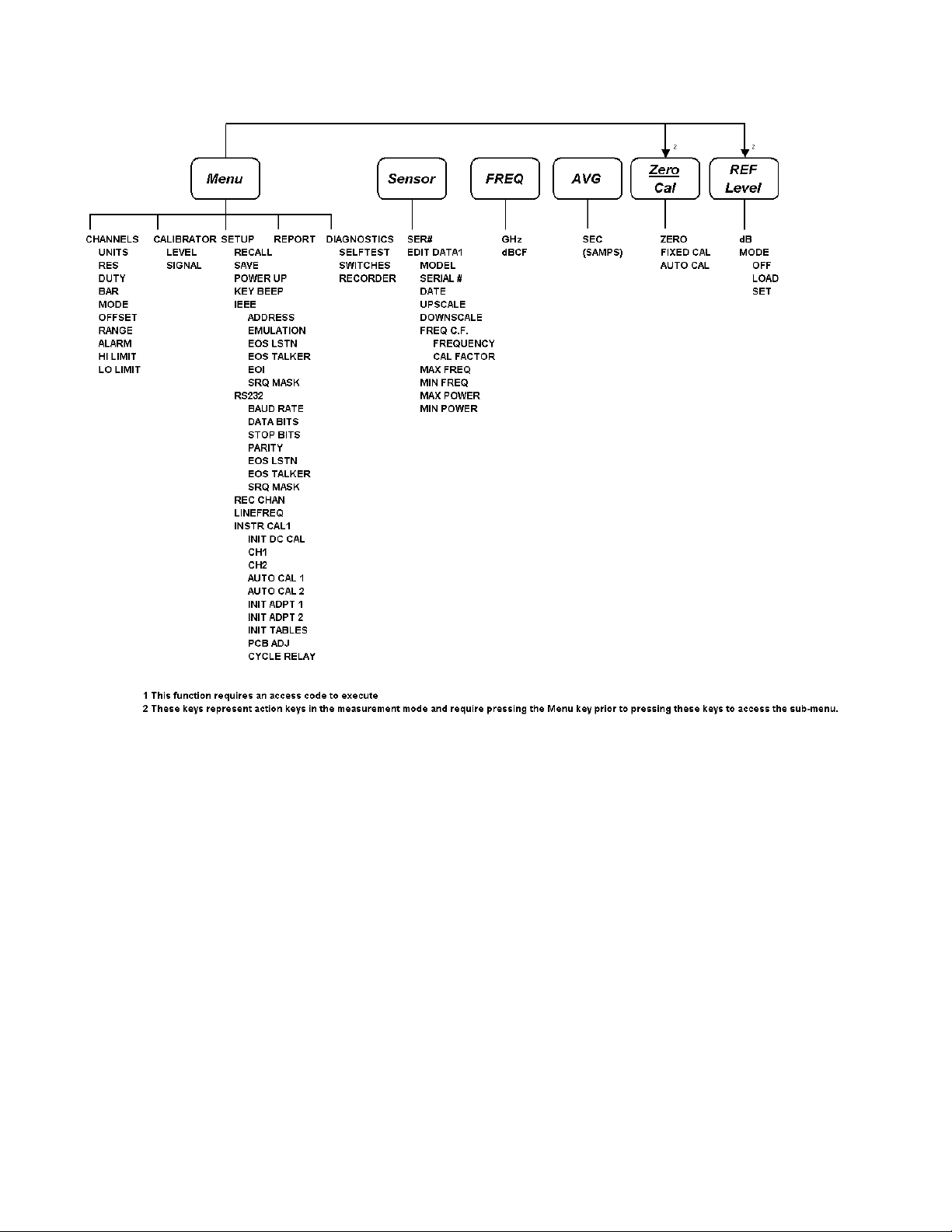
Boonton 4240 Series RF Power Meter
Figure el 4240, Comma
ast Menu Operatio ey stokes to perform a function repeat d , the control program can
L n. In keeping with minimum e ly k
remember the last menu the user was at prior to return he measurement display this submenu functions can
uickly selected and parameters changed getting the u k to the measurement dis r. q
hanged repeatedly recording the measurement results at each level. Firstc
This is a y the following key presses the Calibrator Signal n); <M
to point t ble the setting o level then( TOR) – <Enter> –Next press <En to ena
th el.
<Menu> key returns the instrument to the CALIBRATOR
In this exa ey strokes are eliminated wh not seem like a lot levels
remembering the last menu will save a lot time.
Once in a e previous menu can always be reached by depressing the w> until
k p level menu.
ccomplished b (assuming is already O enu> – <Down Arrow>
o CALIBRA ter> f the desired press <Enter> to set
e calibrator to that lev
ow pressing the <Me ent to the measurement display. To change the level simply pressing the
mple two k ich may but if many are needed to be tested,
submenu, th <Up Arro RTN or escape to the
arent me user exits to the measurement s is methodp <Left Arrow> key. If the
ey will bring up the to
nu using the out creen by th , pressing the <Menu>
3-8
3-5. Mod nd Set
ing to t . In doing be
ser bac play faste
g the internal calibrato e output level needs to be
sin r. ThFor example, suppose the user wants to check the sensors linearity u
, the CALIBRATOR LEVEL function is selected.
rumN nu> key will return the inst
LEVEL function.
Getting Started
Page 33

Boonton 4240 Series RF Power Meter
3.3.1 Menu Key.
he instrument's, CHA P, REPORT and DIAGNOSTIC functions are accessed when the
T NNELS, CALIBRATOR, SETU
<Menu> key is pressed. Using the up/down arrow keys, the cur
sor can be positioned to select from the five submenus.
Channel M ample of the display for the Ch menu is sh lthoug
ines, the i e, it will be p/dowl n only display four at a time. T
rough the commands the instrument will retain the first line as a header and use the next
th . When viewing the commands,
ree lines to scroll thro
able 3-2 gives a desc ailable from the Channels menu. The associated parameters, and factory
default settings are also given.
he comman ttings of the C r menu. t tes and default se
Setup Menu ple of the display for the Setu is shown in Fig e necess
equencing through the commands, the instrument will retains
rough the command list.
th
enu. An ex annels own in Figure 3-7. A h the figure shows eleven
nstrument ca herefor necessary to use the u n arrow keys to sequence
s. th ugh the remaining command
avT ription of the commands
Menu. An Calibrator example of the display for the or menu is show Table 3
ds, parame alibrato
. An exam p menu ure 3-9. It will b ary to use the up/down
R T N
C H A N N E L S <
C A L I B R A T O R
S E T U P
R E P O R T
D A G N O S I S T I C
U N W T T S I T S > A
R E S X X X X
D U 1 0 T Y 0 0 . 0
B A R N O
M O D E
O F F S E T . 0 0 0
R A N G E A U T O
A L A R M O F F
H I L I M I T 9 9 . 9 9
L . 9 O L I M I T - 9 9 9
F u C n M u is y
ig re 3-7. ha nels en D pla
Calibrat n in Figure 3-8. -3 gives a description of
re more than fo rmation tarrow keys to sequence through the commands since there a
the first line as a header and use the next three lines to scroll
Figure 3-6. Main Menu Display
C E RR T N H 1 P O W
ur lines of info o be displayed. When
Getting Started
3-9
Page 34

Boonton 4240 Series RF Power Meter
Table 3-2 CHANNEL MENU Functions
Function De Parameters Defaults
RTN e n e tr e o
r u e .
NITS Units used for measur dBm
U ement dBm, WATTS
RES Display resolution
DUTY Duty cycle for pulse power 0.01 to 100.00% 100.00
applications; a value less than
100.00 enables pulse power
mode.
BAR Enables the bar graph on ON, OFF ON the
measurement display.
MODE Sets the display mode for H
units for sum and ratio modes
channel 2.
OFFSE Sets the offset added to the -99.99 0.00
measured value.
RANGE Selects and hols the instrument’s
measurement range. If
repetitive measurements are to
be made over a narrow range o
instrument range may speed
A Enables alarm
the channel mode designator
the measurement display to
lower threshold limit is
H
LO LIMIT Lower threshold limit for the -99.99 to 99.99 -99.99
T to 99.99 dB
LARM mode; the ∨ or ON, OFF OFF
I LIMIT Upper threshold limit for the -99.99 to 99.99 99.99
scription
R tur s th ins um nt t the n/a
p evio s m nu
display.
channel 2; only available when O
two channels are installed. The
track the units selected for
levels, selecting the appropriate
measurements.
∧ symbol is displayed before
on
indicate when the upper or
Exceeded.
alarm function.
alarm function.
X.X, X.XX, X.XXX dBm or/ X.XX
XXX, XXXX, XXXXX Watts
C 2,CH1+2, CH1/2 CH2
FF
AUTO, 0,1,2,3,4,5,6 AUTO
f
3-10
Getting Started
Page 35

Boonton 4240 Series RF Power Meter
R T N
L E L 6 V E > - 0 . 0
S I L G N A O F F
Figure 3-8. Calibrator Menu Display
able 3-3 CALIBRATOR MENU Functions
T
unction Description Parameters Defaults
F
RTN Returns the instrument to the n/a
LEVEL The calibrator output level in
IGNAL Sets the calibrator output on ON, OFF OFF
S
able 3-4 SETUP nctions
T MENU Fu
Function Description Parameters Defaults
RTN Returns the instrument to the n/a
RECALL R ll ten user DEF , 0 DEF
d e s NITIZE
configurations
setup.
previous menu.
-60.0 to +20.0 -60.0
dBm.
or off.
R T N
R E C A L L > 1
S A V E 2
P O W E R U P F A U T D E L
K E Y B E E P O F F
I E E E
R S 2 3 2
R N E C C H A C H 1
L Q I N E F R E
I A L N S T R C
Figure 3-9. Setup Menu Display
previous menu.
eca s one of AULT 1-1 , AULT
efin d in trument SA
or the factory
1
1
SANITIZE izes l p ram oca ons o D FA
initial al rog l ti t E ULT settings
Getting Started
3-11
Page 36

Boonton 4240 Series RF Power Meter
Table 3-4 SETUP MENU Functions n u
Function De rs Defaults
SAVE Saves the current instrument 1- 0 1
configuration to one
non-volatile memory
OWER-UP Instructs the instrument to pP
to the specified configuratio
KEY B Turns on/off the key beep. ON, O
IEEE menu.
RS232 Brings the instrument to the see table 3-6 n/a
IEEE Menu. The IEEE submenu is used to confi 4240 for communications r the GPIB. An exampl
menu is shown in Figure 3-10 and the description o ands, parameters and facto aults is given in Table 3
EEP OFF FF
EE Brings the instrument to the see table 3-5 IE
INEFREQ Select line (mains) frequency. 50Hz, 60Hz n/a L
STR CAL Refer to Service Manual. n/a n/a IN
scription Paramete
locations.
RS-232 menu.
R T N
A D D R E S S > 1 3
E M U L A T I O P I N S C
E O S L S T N F C R L
E O S T A L K F E R C R L
E O I O N
S R Q M A S K 0
(co tin ed)
1
of ten
ower-up DEFAULT, 1-10 DEFAULT
n.
n/a
gure the Model ove e of the
f the comm ry def -5.
Figure 3-1 EE Men
0. IE u Display
able 3-5 IEEE MENU Functions
T
Function Description Parameters Defaults
RTN Returns the instrument to the n/a
ADDRESS GPIB a ess assign to e to 0 a
in m n
EMULATION G u o od P B , 423 CP
previous menu.
ddr ed th 0 3 n/
stru e t.
PIB em lati n m e. SC I, 437 , 438A 0 S I
3-12
Getting Started
Page 37

Boonton 4240 Series RF Power Meter
Table 3-5 IEEE MENU Functions (continued)
Function Description Parameters Defaults
OS LSTN End of string indicator for LF, CR, CRLF, NONE LF
E
received messages. Where:
L = Li F
C ia
rn
n i Feed
EOS TALKER End of string character sent LF, CR, CRLF, NONE LF
with transmitted mess
OI Enables/disables the end or ON, OFF OFF
E
identify hardware control line.
SRQ MASK Service request interrupt m 0 to 255 0
See Table 4-7 for bit Where:
descriptions. 255
S232 Menu. The RS232 menu is used to configure the Model 4240 for serial communications over the RS-232 bus. An
R
example of the submenu is shown in Figure 3-11 and an
given in Table 3-6.
R T N
B A U D R E 0 A T > 3 8 4 0
D A T A B I T S 8
S T O P B I T S 1
P A R I T Y N O N E
E O S L S T N L F
E O S T A L K E R C R L F
S R Q M A S K 0
ages.
ask.
Figure 3-11
able 3-6 RS232 MENU Functions
T
Function De
RTN Returns the instrument to the n/a
previous menu.
BAUD RATE Rate at which data is 300, 600, 1200, 2400, 4800, 38400
transferred over the bus. 9600, 19200, 38400, 57600,
115200
ATA BITS Number of data bits in a message. 7, 8 8 D
STOP BITS Number of stop bits in a message. 1, 2 1
scription Parameters Defaults
F ne eed
R = Carr ge Return
CRLF = Carriag e Retu
ne
enables all interrupts
explanation of the commands, parameters and factory defaults is
. RS232 Menu Display
a d L
Getting Started
3-13
Page 38

Boonton 4240 Series RF Power Meter
Table 3-6 RS232 MENU Functions (continued)
Function Description rs e u
PARITY bit mode in a m ssage. ODD, NONE
EOS LSTN d s g d t o LF, , ,
received messages. Where:
CRLF = Carriage Return
and Line Feed
EOS TALKER End of string character sent LF, CR, CRLF, NONE CRLF
with transmitted messages.
SRQ MASK Service request interrupt mask. 0 to 255 0
See Section 5.5.1 *STB? for bit Where:
descriptions. 255 enables all interrupts
EPORT Display. The REPORT menu item displays the versions of the firmware and FPGA image installed in the
R
strument. The SCPI specification compliance version is also displayed in this report. This display is for informational
in
urposes only and does not support any editing is shown in Figure 3-12.
p of the data. The REPORT display
iagnostics Menu. The Model 4240 can be directed to perform self-tests from the diagnostics menu. The Diagnostics menu is
D
shown in Figure 3-13 a s io of ch com and is in a e .
Parity e EVEN, NONE
En of trin in ica or f r CR CRLF NONE LF
V E R S I O N
F I R M W A R E 2 0 1 0 0 7 1 1
F P G A 1 . 1 8
S C P I 1 9 9 0
Figure 3-12. Report Display
and de cript n ea m given T bl 3-7
R T N
S E L F T E S T <
S W I T C H E S
R E C O R D E R
u 3 . Diag o c la
Fig re -13 n sti s Disp y
Table 3-7 DIAGNOSTICS MENU Functions
unction Description Parameters Defaults
F
TN Returns the instrument to the n/a n/a
R
previous menu.
Paramete D fa lts
LF = Line Feed
CR = Carriage Return
3-14
Getting Started
Page 39

Boonton 4240 Series RF Power Meter
Table 3-7 DIAGNOSTICS MENU Functions (continued)
Function Description Parameters Defaults
SELF TEST Instructs the instrument to n/a n/a
and the display test.
SWITCHES Interactive test to verify proper
switches.
ECORDER The recorder output DAC is n/a n/a
R
from 0 to 10 V.D.C. in 1V steps
key is depressed.
.3.2 Sensor Key.
3
perform internal diagnostics
n/a n/a
operation of the front panel
exercised through its full range
continuously until the <Menu>
Pressing th ey brings the instrument to th enu and facilitates v d ed
paramete code is required to enter the e ode (refer to ple
shown . is
The instrument is capable of using sensor calibration data from either the
tables. The sensor calibration data contained with sor data adapter is only accessible to the installed chan
example, Channel 1 can use the sensor calibration any of the internal tables o ensor data adapter 1. Si
Channel nsor calibration dat nternal tables o pter 2.
Referring to Figure 3-14, the cursor can be positioned to three fields. The two fields below the 'CH1' and 'CH2' indicate the
rial number of the sensor whose calibration data is selected fo 2 respectively. The instrument uses this data
se r channels 1 and
r the linearity and high frequency correction data and automatically applies the correction to the measured value.
fo
To change the selection for channel 1, use keys to move to and lin
arameter list typically consists of serial numbers for each powep
is displayed a Enter> to accept. Move the c ow the 'CH2' fiel same procedure used t
the table for channel 2.
The instrument detects the presence of the sensor d r and automatically do he s
ccurs when the o the unit is first applied lugging the sensor da ntoo
sensor and corre ng sensor data adapter have serial numbers for main m as
e <Sensor> k e Sensor m iewing an iting of the power sensor's
rs. An access diting m Figure 3-15). A sam display of the Sensor menu
in Figure 3-14
sensor data adapters or from any one of four internal
in the sen nel. For
data from r the s milarly,
2 can use the se a from any of the i r the sensor data ada
C C
S E R # > 2 9 3 9 1 3 3 3 7 2
E D I T D A T A 1 2 9 3 9
current the arrow the SER# comm e and position the cursor
nd press < ursor bel d and follow the o change
power t or after p ta adapter i the instrument. The power
spondi matching taining the a matched pair.
H 1 H 2
ure 3 rFig -14. Senso Display Menu
the u s to scroll th h the parameter list. The
p/down arrow key rougbelow the 'CH1' field. Press the <Enter> key and use
r sensor. Scroll through the list until the desired serial number
ata adapte wn-loads t ensor calibration data. This
EDIT DATA ACCESS CODE
Getting Started
3-15
Page 40

Boonton 4240 Series RF Power Meter
R T N
M > 5 1 0 7 O D E L 5
S # 2 9 3 9 E R I A L 1
D 0 8 2 A T E 3 1 0
U 0 : 5 0 P S C A L E 0 0
D O W 0 N S C A L E 0 : 0 0 0
F R E Q C . F .
M A X F R E Q 1 8 . 0 0
M I N F R E Q 0 . 0 0
M A X P O W E R 2 3 . 0 0
M I N P O W E R - 7 5 . 0 0
The parameter list will show TBLn (where n = 1, 2, 3, 4) when a serial number has not been entered for the corresponding
internal table. For example, TBL3 will be displayed if the serial number has not been previously entered for internal table 3. In
addition, the parameter list will show ADPTn (where n = 1, 2) if a serial number has not been entered for the table contained
within the sensor data adapter. For example, ADPT2 is displayed when the serial number has not been previously entered for
sensor data adapter 2.
To edit the sensor calibration data, move the cursor to the EDIT DATA function and press <Enter>. Scroll through the power
sensor serial numbers until the desired selection is displayed. Press <Enter> to proceed. Enter the access code to edit or
depress the <Menu> key to escape. (See Figure 3-15.)
Sensor Edit Data Menu. An example of the Edit Data menu is shown in Figure 3-16. Table 3-8 contains a description of the
commands and associated parameters.
The access code to enter the Edit Data menu is as follows:
Press the front panel switches in the following order:
<FREQ> <AVG> <AVG> <FREQ> <Sensor> <Enter>
Figure 3-15. Access Code
Figure 3-16. Sensor Edit Data Menu Display
Table 3-8 Sensor Edit Data Menu Functions
Function Description Parameters Defaults
RTN Returns the instrument to the n/a n/a
MODEL Power sensor model number 0 to 99999 0
SER # Power sensor serial number 0 to 99999 0
Table 3-8 Sensor Edit Data Menu Functions
(continued)
3-16
Getting Started
Page 41

Boonton 4240 Series RF Power Meter
Function Description Parameters Defaults
DATE Calibration date MM/DD/YY 01/01/01
Where:
MM = 01 to 12
DD = 01 to 31
YY = 00 to 99
PSCALE Upscale linearity factors RangeU
DOWNSCALE Downscale linearity factors Range : Factor 0
[0 to 6] : [-999 to 999]
REQ C.F. Brings the instrument toF
MAX FREQ Power sensor's maximum 0, 100.00 GHz 18
frequency
MIN FREQ Power sensor's minimum 0, 100.00 GHz 0.03
frequency
AX POWER Power sensor's maximum [-99.99, 99.99] dBm 20
M
MIN POWER Power sensor's minimum [-99.99, 99.99] dBm -75
power input
Linearity Factors. Seven upscale and downscale linearity factors are assigned to each power sensor. These values can be
viewed or edited by moving the cursor to the UPSCALE or DOWNSCALE command and pressing the <Enter> key. The
instrument will sequence through the linearity factors by pressing the up/down arrow keys. If a value is to be edited, scroll to
the desired linearity factor, use the right arrow key to move the cursor to the first digit in value field and then use the up/down
arrow keys to increment/decrement the number. Set the remaining digits in the same manner. If another value needs to be
changed, move the cursor back to the range field and use the up/down arrow keys to display the next value to be modified.
Press the <Enter> key when all of the changes have been entered.
FREQUENCY Calibration Factors. Up s can be entered for each power sensor.
Position the cursor to the FREQ C.F. com o the Cal Factor menu. A sample of the
isplay is shown in Figure 3-17 and an explanation of the commands is shown in Table 3-9.
d
calibration factor menu
R T N F R E Q
0 > 0 0 0 . 0 5 + 0 0 . 0 0
1 - 0 0 . 0 0 0 1 . 0 0 3
- . 2 0 0 2 . 0 0 0 0 0 6
Fi r - uency Cal Facto e Display gu e 3 17. Freq r M nu
the n/a n/a
to 60 sensor freque cy calibration factor
mand. Press the <Enter> key to advance t
: Factor 5000
[0 to 6] : [0 to 9999]
n
C A L
Getting Started
3-17
Page 42
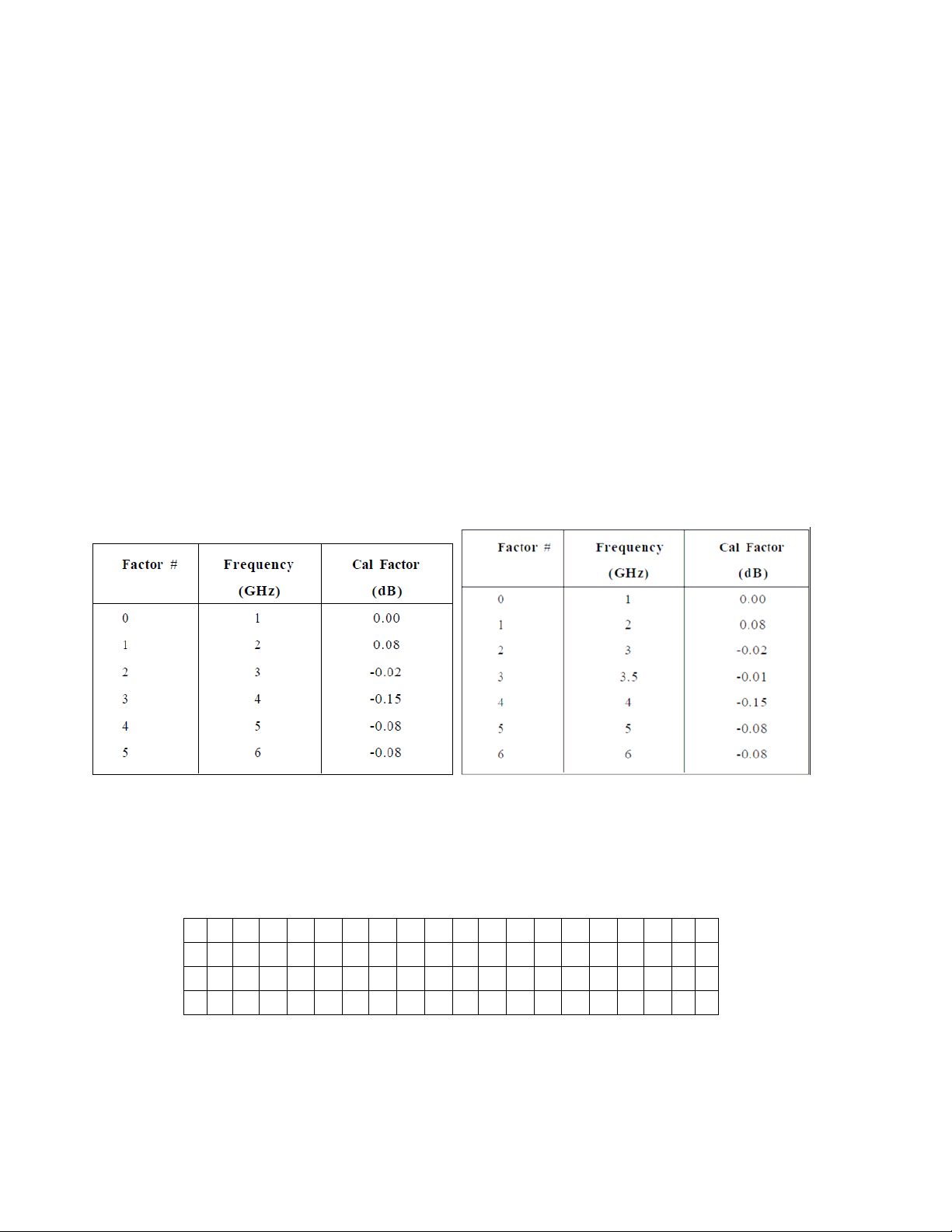
Boonton 4240 Series RF Power Meter
Table 3-9 FREQ Menu Functions
unction Description Parameters Defaults F
FREQ Frequency 0.01 to 100.00 GHz 0.05
CAL High frequency -3.00 to 3.00 dB 0.00
calibration factor
The up/down arrow ke s o r h h t t a e se e ro keys m ve to the desired field
and press the <Enter> k t e va e. The up/down ro k s c / e n h e and the left/right arrows
keys select the digits. nt > whe e si d u s s y . v r t RTN field or depress
the <Menu> key to retu t e Sen m u
nstrument scans the sensor calibration ta ating frequency. Linear interpolation is used
The i
the operating frequency is between two of the table entries. To ensure proper operation, the calibration table must be entered
if
in ascending order an
addition, new calibrati
the -0.01 dB calibration factor at 3.5 GHz to the example shown in Figure 3-18, the calibration factors for items four through
six are re-entered.
ys are u ed t sc oll t rough t e calibra ion fac or t bl . U th ar w to o
ey o chang a lu ar w ey in rement decr me t t e valu
Press the <E er key n th de re val e i di pla ed Mo e the curso to he
rn o th sor en .
d terminated in the last table entry with a zero (0) value for both the FREQ and CAL FACTOR. In
on values should be entered while adhering to the chronological order of the table. For example, to add
ble for a value that matches the oper
Figure 3-18. Calibration Data Example
Save. Exiting the EDIT DATA menu displays the confirmation menu as shown in Figure 3-19. Move the cursor to YES to
save the edited parameters or NO to leave the data unchanged.
3-18
S T O R E S E N S O R D A T A
A R E Y O U S U R E ?
Y E S > N O
Figure 3-19. Save Display
Getting Started
Page 43

Boonton 4240 Series RF Power Meter
3.3.3 FREQ Key.
he freT
quency of the signal being measured must be entered in order to use the stored high frequency calibration factors. The
in
strument will then compute, display and apply the required correction factor to subsequent measurements.
The operating frequency may be set by first pressing the <FREQ> key. The instrument will advance to the Frequency menu as
hown in Figure 3-20. The frequency for s
eading and pressing the <Enter> key. A value between 0.01 GHz and 100 GHz can be entered. The power on default is 0.05
h
Hz. Once the frequency is nt red, the corr spondin Ca Factor is di l d i dB be at h fre ue cy.
G e e e g l sp aye n ne h t e q n
F R E Q U E N C Y
C C H 1 H 2
G H z > 0 1 8 . 0 0 0 2 . 5 0 0
d B C F 0 . 0 2 0 0 0 . 1 0 - 0
3.3.4 AVG Key.
he averaging time may be adjusted to optimize measurement speed and display stability. Averaging time, in seconds, can be
T
adjusted in 0.05 increments to a maximum of 20.00 seconds. The length of the filter in number of samples is shown on the
display.
To adjust the averaging time, press the <AVG> key and the instrument will display the screen as shown in Figure 3-21.
Position the cursor under the desired channel heading and press the <Enter> key. Use the arrow keys to set the desired value
and then press <Enter> to accept. Entering 00.00 selects the auto filtering Mode. This menu can be accessed to show the filter
setting in the auto mode.
T I M E
C H 1 C H 2
S E C > 1 0 . 5 0 0 0 . 0 8
S A M P S 2 1 0 1 6
3.3.5 Zero/Cal Key (single key press operation).
Channel 1 is entered by positioning the cursor to the value field under the CH1
Figure 3-20. Frequency Display
Figure 3-21. Averaging Time Display
Zeroing should be performed when the unit is first warmed-up, a sensor has been changed or the instrument has drifted a
significant amount with respect to the signal level being measured. For large signals (measurements taken on range 4, 5, or 6),
this may be done once every several hours. For small signals, (measurements taken on range 0, 1, 2, or 3), zeroing should be
done before each measurement for optimum results. When zeroi
rrections for each range, and applies the corrections to subsequent measurements.
co
Assigning the <Zero/Cal> y as a op at n allo s for a f st zero th e hardware range to avoid
the longer zeroing pr es When he e h s measuri l e p x a 0 dBm, and if the
measurement is settled hat is, if th il is ll e g e e C > y will take rement as the zero
reference. This allow r ter an o m s m ts of w v i l rement is not settled the
complete zeroing process ll g is e m .
ke
s.
, t e f ter fu , pr ssin th <Z ro/ al ke the displayed measu
s fo fas
of a
sing tle key press Cer io
d mesre pactu
ran
rateedea ure en lo le el s gna s. If the measu
rfor
i
Getting Started
ng is performed, the instrument calculates and stores zero
w a ing
elowof ap
e lowrost
telyoc Activ annel ng ev ls b im -5
3-19
Page 44

Boonton 4240 Series RF Power Meter
he user may also perform a 0 dBm calibration by one key stT roke of the Zero/Cal key. Simply connect the sensor to a 0 dBm
source (either by setting the internal 50MHz calib dBm or connecting to an ex l 0 dBm source) and p
Zero/Cal> key. The instrument detects that a 0 dB s present and sets a calibratio or accordingly to indicate 0<
dBm.
he Zero/Cal menu is displayed by first pressing the <Menu> key followed by the <Zero/Cal> key. From there the user
T
chooses t ero, Fixed Cal, Auto Cal) and th annel to perform the cal n. Th
th wn in Figure 3-22.
ZERO – performs zeroing of all hardware ranges of the selected channel.
FIXED CAL – the internal 50MHz calibrator is set to 0 dBm and a calibration is performed at that point. Fixed Cal may
performed on any 0 dBm source other than the internal calibrator.
The built-in 50 MHz calibrator provides a convenient means for calibrating the instrument. Calibration can be performed any
time to assure accuracy.
UTO CAL – improved sensor shaping can be realized by performing a step calibration using the 50 MHz Step Calibrator.
A
o perform an AutoCal, connect the sensor to be calibrated to the desired measurement channel and to the front panel CAL
T
UT connector. Press the <Menu> key followed by the <Zero/Cal> key. The Zero/Cal menu will be displayed. Navigate the
O
ursor to the AUTO CAL line and select the channel to have the auto cal performed on. Press the <Enter> key to being the
c
UTO CAL process. The instrument will return to the measurement window upon completion of the calibration.
A
he function (Z e ch ibration o e Zero/Cal menu invokes
ree commands as sho
Z E R O <
F I X E D C A L
A U T O C A L
Figure 3-22. Zero and Calibration Display
rator to 0 terna ress the
m signal i n fact .00
C H 1 C H 2
be
.3.6 REL Level Key (single key press operation).
3
ften relative measurements are required especially when measuring system gains and losses. One key press of the
O
Ref/Level> key makes this job easier and faster to perform. Simply connect the active channel’s sensor to the input signal of
<
e system under test. Press the <Ref/Level> key and the reference level is set! Next connect the sensor to the system output
th
nd read the gain or loss directly from the reference level measurement.
a
he REF Level menu is displayed by first pressing the <Menu> key followed by the <REF Level> key. From there the user
T
ay SET (entering a value ) or LOAD (use the current channel measurement ) the reference level on either channel.
m
ress the <REF Level> key to enter a value or to use the current channel measurement for the reference level. The
P
easurement units will automatically change to dBr for logrythmic units or % for linear units for subsequent measurements.
m
n example of the instrument's display is shown in Figure 3-23.
A
R E F E R E N C E L E V E L
C H 1 C H 2
d B > + 0 0 . 0 0 + 2 5 . 0 0
M O D E L O A D S E T
Figure 3-23. Zero and Calibration Display
3-20
Getting Started
Page 45

Boonton 4240 Series RF Power Meter
Table 3-10 Reference Level Menu Functions
unction Description Parameters Defaults
F
Bm Reference level value in Preset -99.99 to 99.99 dBm 0
d
ODE Reference level mode. "LOAD" LOAD, SET, OFF OFF
M
o set a reference level, depress the <REF Level> key to display the REFERENCE LEVEL menu. Move the cursor to the
T
reference value for the appropriate channel. (Channel 1is defau .) Depress the <Enter> key to initiate the editing process. Use
the arrow keys to edit the reference value in dBm. Once the desired value has been selected, depress the <Enter> key to leave
the editing function. To use this value as the reference, depress the <Down> arrow key to MODE, depress the <Enter> key for
mode selection and using the <Up> or <Down> arrow keys, select SET. Depressing the <Enter> key will place the appropriate
channel to the "dBr" mode of operation using the set value as th reference.
The instrument can also load the curre , depress the <REF Level> key to
display the REFERENCE LEVEL su the MODE selection of the desired
annel. Depress the <Enter> key for mode selection and using the <Up> or <Down> arrow keys, select LOAD. Depressing
ch
the <Enter> key will place the appropriate channel to the dBr mode of operation using the measured value as the reference
level.
mode.
makes the current channel
measurement as the reference level.
The Set mode is used to select the
entered reference level. The Off mode
disables the reference level
adjustment.
nt measured value as the reference level. To do this
b-menu. Navigate the cursor using the arrow keys to
lt
e
Getting Started
3-21
Page 46

Boonton 4240 Series RF Power Meter
This page intentionally left blank.
3-22
Getting Started
Page 47

Boonton 4240 Series RF Power Meter
4. Operation
This section provides detailed background information on various aspects of operation of the Model 4240. It is assumed that
the reader is familiar with the basic operating procedures covered in Section 3. This section covers the following topics:
Sensor calibration, Zeroing, Filtering, Noise, Dynamic range, Measurement time, High frequency accuracy, Chart recorder
operation and Waveform sensitivity.
4.1 Sensor Calibration
General. Two types of calibration are associated with the Model 4240 - instrument calibration and sensor calibration. The
instrument (less sensors) must be calibrated using a stable and accurate DC source, such as the Boonton Model 2510, to
ensure interchangeability of sensors. Instrument calibration procedures are covered in the Model 4240 Service Manual.
Sensor calibration data is of two types: linearity and high frequency calibration factors. Sensor calibration data for up to four
sensors can be stored in nonvolatile EEPROM plus each sensor data adapter contains the data matched to the corresponding
power sensor.
14-Point Linearity Data. Linearity data, also referred to as AC reference frequency linearity data, is supplied with the sensor
and can be manually entered into the non-volatile Tables or Adapters. For sensors ordered with the instrument, linearity data
is stored in the sensor data adapter before the instrument is shipped.
At the reference frequency (50 MHz, or 40, 60, or 94 GHz), each sensor has two gain factors for each range: upscale and
downscale points. Refer to Figure 4-1. The upscale points are in the range of 4000-7000, which is a gain correction factor.
Upscale points are calibrated at the factory at about 70% of full scale. The downscale number is an offset correction at about
25% of full scale. Thus, for a diode sensor (7 ranges), there are 14 points; for thermal sensors there are eight points. Ranges 0
and 1 share the same data points.
AutoCal. Initiates a multi-point sensor gain calibration of the selected sensor with the internal 50MHz step calibrator. This
procedure calibrates the sensor’s linearity at a number of points across its entire dynamic range. A sensor must be connected
to the channel input.
High Frequency Calibration Points. In addition to linearity data, there are high frequency calibration points. Calibration
points covering the entire sensor frequency range are supplied with each sensor. Below 1 GHz, the sensor response is flat,
and frequency calibration points need not be entered.
The Model 4240 provides space for up to 60 points for each sensor table. Frequency calibration points need not be in equal
frequency increments; however, the entry of data must be done in ascending order of frequency. For both diode and thermal
sensors, a calibration factor of 0 dB is implied at 0.00 GHz so that the instrument may be operated below the first data point.
4.2 Zeroing
The automatic zeroing routine of the instrument takes measurements on the lowest five ranges and applies these as correction
factors on subsequent measurements. Offsets in the sensor and input amplifiers are linearly corrected in the internal software.
Offsets on the highest ranges are below 0.02% of full scale, and do not need correction.
Input power to the sensor must be removed before the zeroing function is executed or an error message will be displayed. The
instrument will perform zeroing, however, if the signal is less than full scale on range 0. This feature provides a great deal of
offset capability for temperature effects without rezeroing the input amplifier hardware.
For full accuracy at low signal levels, power must be removed from the sensor several seconds before zeroing to allow the
sensor to settle. This is especially true if a large signal had been applied to the sensor in the previous 20 seconds or so
because of the dielectric absorption of the capacitors in diode sensors, and because of thermal retention in thermal sensors.
The error resulting from different input conditions can be determined from Figure 4-2 or 4-3, as applicable. The curves in
Operation
4-1
Page 48
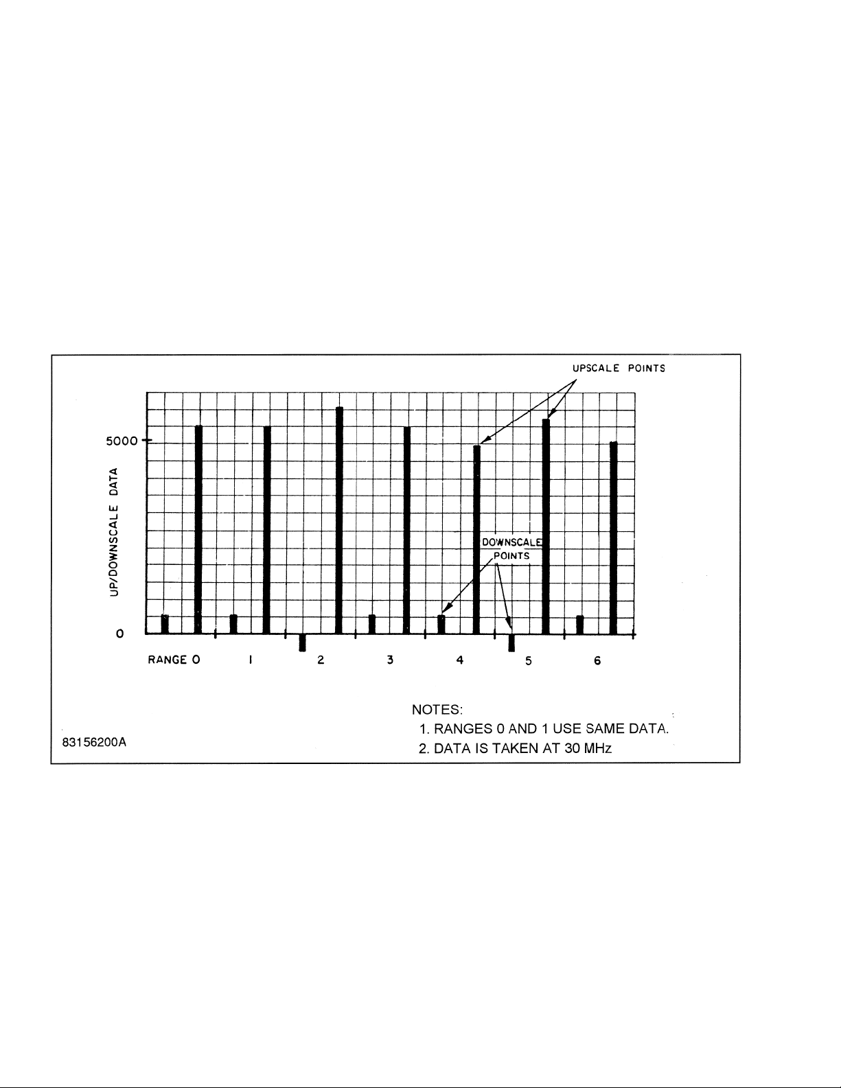
Boonton 4240 Series RF Power Meter
these figures show the decay of measured power after a large signal has been applied. The typical error that can be expected
by zeroing too quickly after application of a large signal is equal to the offset power at the time of zeroing.
The Model 4240 initiates zeroing when the ZERO command is invoked. The user must delay zeroing according to system
requirements when the sensors are used over a wide dynamic range. For example, if it is determined from the application that
five seconds are required from power off to the zeroing operation, then the user should wait five seconds after removing
power from the sensor before executing the zero command.
The zeroing time on each range has been optimized for speed and accuracy. Total zeroing time is approximately 20 seconds.
Zeroing should be done when the instrument is turned on, the sensor has been changed, or the instrument has drifted a
significant amount with respect to the signal being measured. For large signals (range 4, 5, or 6), this may be once every
several hours, if at all. For very small signals (range 0, 1, 2, or 3), for optimum results, zeroing be done immediately before
each measurement.
Figure 4-1. 14-Point Sensor Calibration
4-2
Operation
Page 49
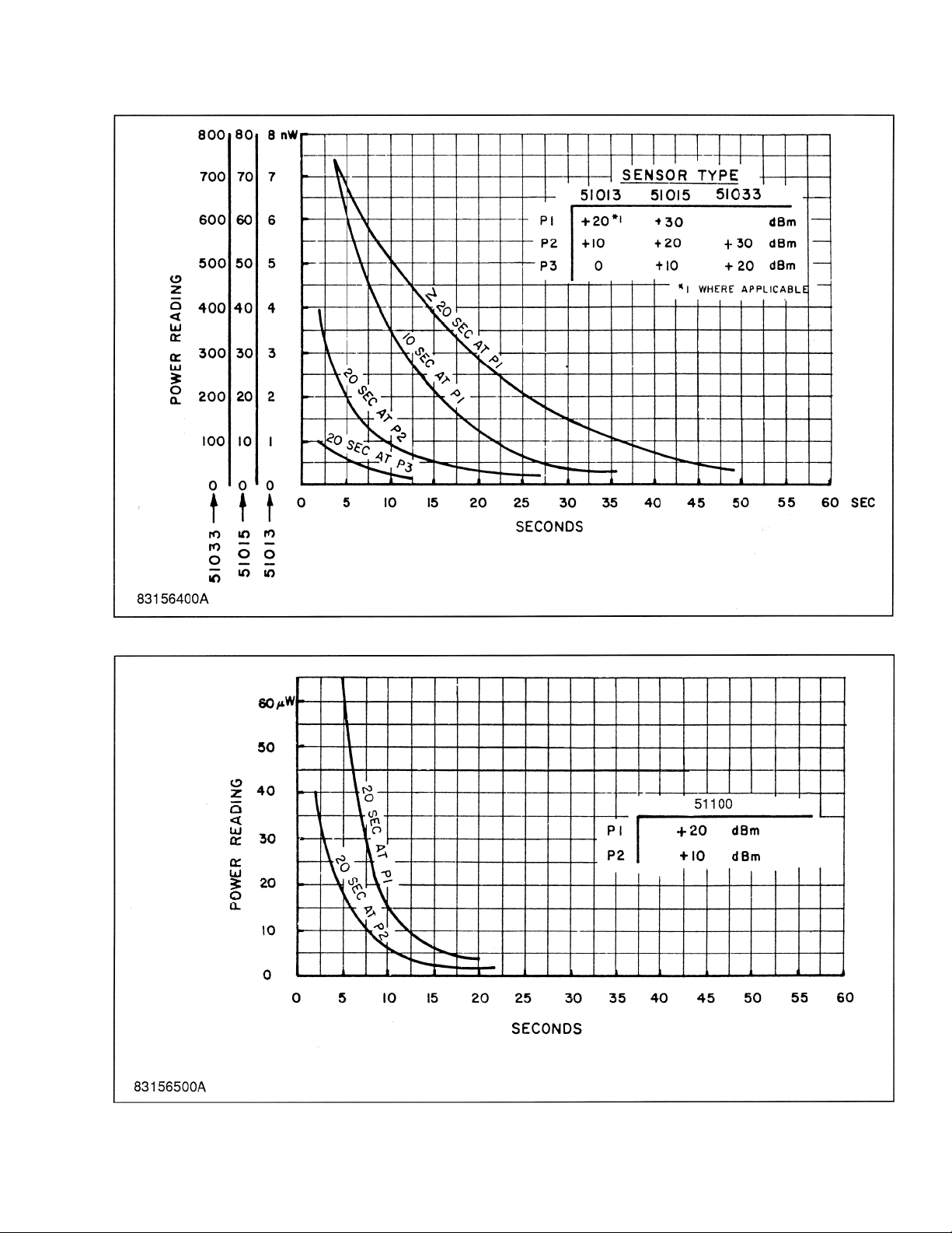
Boonton 4240 Series RF Power Meter
Figure 4-2 Diode Sensor Decay
Operation
4-3
Page 50
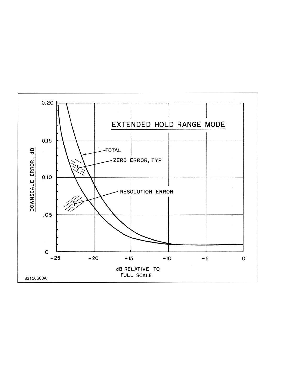
Boonton 4240 Series RF Power Meter
Figure 4-3 Thermal Sensor Decay
4.3 Dynamic Range
The hold range mode is useful when he hold range mode
is active when a specific instrument ect nge of this mode is
limited by the zero offset and the reso ee t the useful dynamic
nge is 20 dB if the error is to be kep for e measured value is
below the lower range limit indicating an uncalibrated measurement.
it is known that the signal will vary over a certain limited range. (T
range, other than autorange, has been sel ed.) The dynamic ra
lution, as shown in Figure 4-4. It can be s n from this figure tha
t below 0.1 dB. An asterisk is displayed be e the channel when thra
Figure 4-4. Extended Hold Range Mode
4-4
Operation
Page 51

Boonton 4240 Series RF Power Meter
4.4 Filtering
The Model 4240 employs digital filtering (averaging of measurements) to reduce the noise floor of the instrument and to
stabilize measurements. The default values are optimized for speed and low noise under general conditions. Default values
for normal and fast modes are as follows:
Range Normal (sec.) Fast (sec.)
0 2.8 2.8
1 0.8 0.8
2 0.8 0
3 0.8 0
4 0.8 0
5 0.8 0
6 0.8 0
The filtering technique used is digital pipeline filtering, also referred to as circular filtering or moving average filtering. The
displayed measurement is simply an equally weighted average of the last x seconds worth of samples, where x is the filter
length in seconds. For purposes of noise and settling time, the number of samples is not important, but the time is important.
For example, if a three second filter is used, the noise is the same whether 60 or 600 samples are taken in that interval,
provided that the samples are taken above a certain rate. For this reason, filter selection in the Model 4240 is done on the
basis of seconds, rather than the number of samples.
The bottom end sensitivity of the instrument is limited by sensor noise. An RMS noise specification is valid since the sensor
noise and the amplifier noise are band-limited and Gaussian. The noise level, specified in picowatts at a certain filter length,
is sufficient to calculate the error due to noise at any signal level, for any filter, as shown in the discussion of noise that
follows.
4.5 Noise
Noise Reduction. The amount of noise reduction that can be realized has no theoretical limitation, except that drift enters
into the picture at filter lengths over 20 seconds. The digital filter has a bandwidth and rolloff curve just as any filter does; the
bandwidth can be reduced arbitrarily. The effective noise bandwidth is 0.469/t, where it is the filter length. For example, with
a filter length of 4 seconds, the equivalent noise bandwidth is 0.12 Hz.
Figure 4-5 is a nomograph showing the noise reduction that applies for various filter lengths, given the sensor noise with 2.8
second filtering. (This is the time for which diode sensor noise is specified.) Noise power is inversely proportional to the
square root of the filter length. Normally, noise power varies directly with filter bandwidth; however, because power sensors
are square-law devices (detected voltage is proportional to power), the noise power is proportional to the square root of the
bandwidth. This can be demonstrated with noise measurements. At very low filter lengths (less than 150 milliseconds),
however, the noise does not increase without bound for all sensors because the input amplifier noise is restricted with
hardware filters. This additional filtering is not shown in the nomograph.
Error Computation. Since the noise is Gaussian, both before and after filtering, statistics show the level of confidence
factor that can be associated with a given reading. (At medium and high power levels, the confidence factor is essentially
unity.) Figure 4-6 shows a typical set of samples and a typical error band specification of 2 sigma. Under these conditions,
95.4% of the readings will fall within +
Figure 4-7 shows the confidence factor for other error bands. The error band is expressed in pW, regardless of the power
level. (The percentage error band can also be calculated as shown below.) The RMS noise is taken from the sensor
specifications and modified as necessary for filter lengths other than 2.8 seconds. Knowing any two of the three parameters
(error band, RMS noise, and confidence factor), the third can be computed. For example, if the sensor RMS noise is 65 pW
and the confidence factor is to be 95.4%, the sided (+130 pW). If this were the case, at a
measurement level of 1300 pW the percent erro ding to about +0.44 dB.
2 sigma.
error band is 130 pW, single
r band would be 10%, correspon
Operation
4-5
Page 52
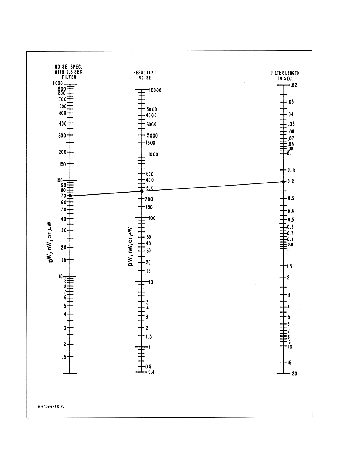
Boonton 4240 Series RF Power Meter
4-6
Operation
Page 53
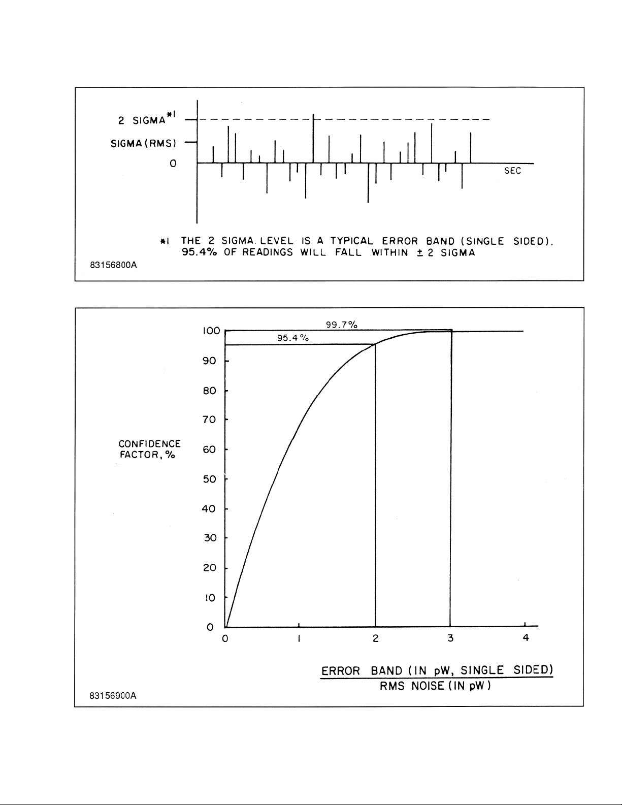
Boonton 4240 Series RF Power Meter
Figure 4-5. Noise Reduction
Figure 4-6. Typical Error Band Specifications
Figure 4-7. Probability of Falling within an Error Band
Operation
4-7
Page 54
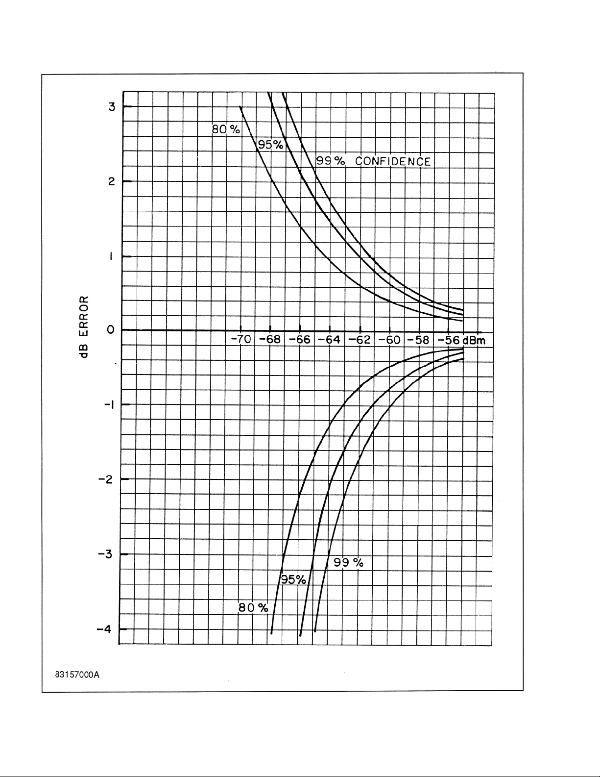
Boonton 4240 Series RF Power Meter
4-8
Figure 4-8. Confidence Curves, 51013 Sensor with 2.8 Second Filter
Operation
Page 55
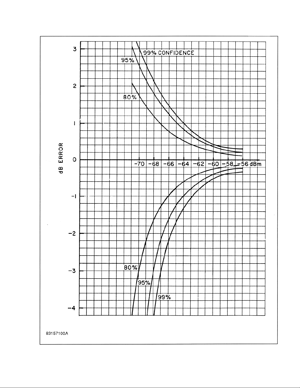
Boonton 4240 Series RF Power Meter
Figure 4-9. Confidence Curves, 51013 Sensor with 10 Second Filter
Operation
4-9
Page 56
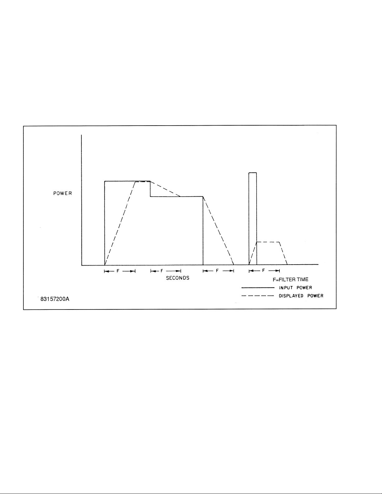
Boonton 4240 Series RF Power Meter
Noise Error Examples. Figures 4-8 and 4-9 show the computed error for the 51013 diode sensor at different power levels,
for 2.8 and 10 second filters. To attain these results, the sensor must be at a stable temperature, and zeroing must be done
immediately before the measurement is taken.
Integration of Power. With long filtering, instrument readings may seem erroneous because the filter has not been cleared.
For example, with a 20 second filter, if a 2 second RF pulse is applied, the instrument display will indicate a nonzero level for
18 seconds after the pulse has terminated. Additional pulses will be integrated along with the first until, by the process of
selective deletion, the pulses are removed one at a time from the filter. Actually, measurement samples are deleted, not the
pulses, giving rise to a ramping effect at the instrument display/output. This is shown in Figure 4-10. In all senses, the filter
is a simple integrator.
Figure 4-10. Integration of Power
Clearing of Filter. When long filter times are used, it may become troublesome at times to wait for the filter to clear. If the
Auto filter function is selected, the filter is cleared after significant power changes, and filtering then resumes. Clearing can
also be accomplished by changing the filter length to any different value and then resetting it using the interface bus;
however, with bus operation, most of the trigger modes clear the filter at trigger time.
Partial Results. Measurement time is affected by the filter since valid readings to within a certain error band can be obtained
only when the filter is full. If the filter has been cleared, data is available at reduced accuracy immediately after the first 50
millisecond sample period. The filter uses the number of samples as a divisor when computing the average, and the
output/display does not ramp but homes in on the result instead as the samples accumulate.
.6 Measurement Time
4
tep Response. The measurement time fromS
filter, where the overhead time is defined as the time delay due to sensor response time and measurement software
(processing).
4-10
a power input step is the sum of the overhead time and the length of the digital
Operation
Page 57

Boonton 4240 Series RF Power Meter
ontinuous Response. Regardless of the overhead time or the digital filter length, the Model 4240 will output readings at a
C
maximum rate of about 200/second with the display operating. As the sensor and the digital filter settle, readings will ramp
up or down at that rate.
Overhead Time. Overhead time is <350 milliseconds for diode sensors and <450 milliseconds for thermal sensors under the
following conditions:
Settling to 99% or 0.04 dB of final power
a.
b. Power step of 10 dB
c. Range does not change
d. Digital filter set to minimum
The power step may be upward or downward. Smaller power steps will d
ownward direction will increase the time significantly. A 40 dB downward step, for example, will take several seconds to
d
settle to 0.04 dB.
igital Filter. The digital filter is a m e readings over the last x
D oving average or pipeline filter which simply integrates th
seconds, where x is the filter length. A step input to the filter will produce a linear ramp at the output, terminating when the
filter is full.
Default Filter Lengths. Although any filter length from 0 to 20 seconds may be chosen, default filter lengths are
rogrammed into the instrument for optimum general conditions. (Refer to Section 4.3 Filtering.) For diode sensors, the
p
range break-points are roughly in 10 dB steps, with the range 0 to 1 break-points at approximately -54 dBm.
Settled Measurement Time. In the free run settled mode, output data updates are held off until the measurements have
settled.
ast Mode Measurement Time. The Fast Mode can be invoked over the bus to put the instrument into its fastest sampling
F
mode.
4.7 High Frequ
Power measurements, particularly at high frequencies, have a number of uncertainties which generally arise from imperfect
SWRs. If all power sources and power meters had impedances that were resistive and equal to Z
impedance of the measuring system), most problems would disappear. The incident, dissipated, and maximum available
powers would all be equal, and the indicated powe
all dissipated power to indicated power. Tuning eliminates most of the SWR effects, but is cumbersome and is therefore
seldom done. The use of attenuator pads can mask imperfect SWRs, as can the use of a directional coupler to level the source
and reduce its reflection coefficient to a value equal to the directivity factor of the directional coupler. Boonton 51015 and
51033 power sensors have precision, built-in attenuators which improve the SWR over that of other power s
hen the complex coefficients of both an impeW
SWRs of both are known, the maximum positive and negative uncertainties of the measured power, Pm, can be determined
from Figure 4-11. For example, if the SWR of the source is known to be 1.2 and the SWR of the power sensor is 1.25, the
uncertainty derived from Figure 4-11 is 2%.
ency Accuracy
r would differ only by the inefficiency of the power sensor in converting
rfect source and a power sensor are not known, but the maximum actual
ecrease this time slightly; larger power steps in the
o (the characteristic
ensors.
Operation
4-11
Page 58
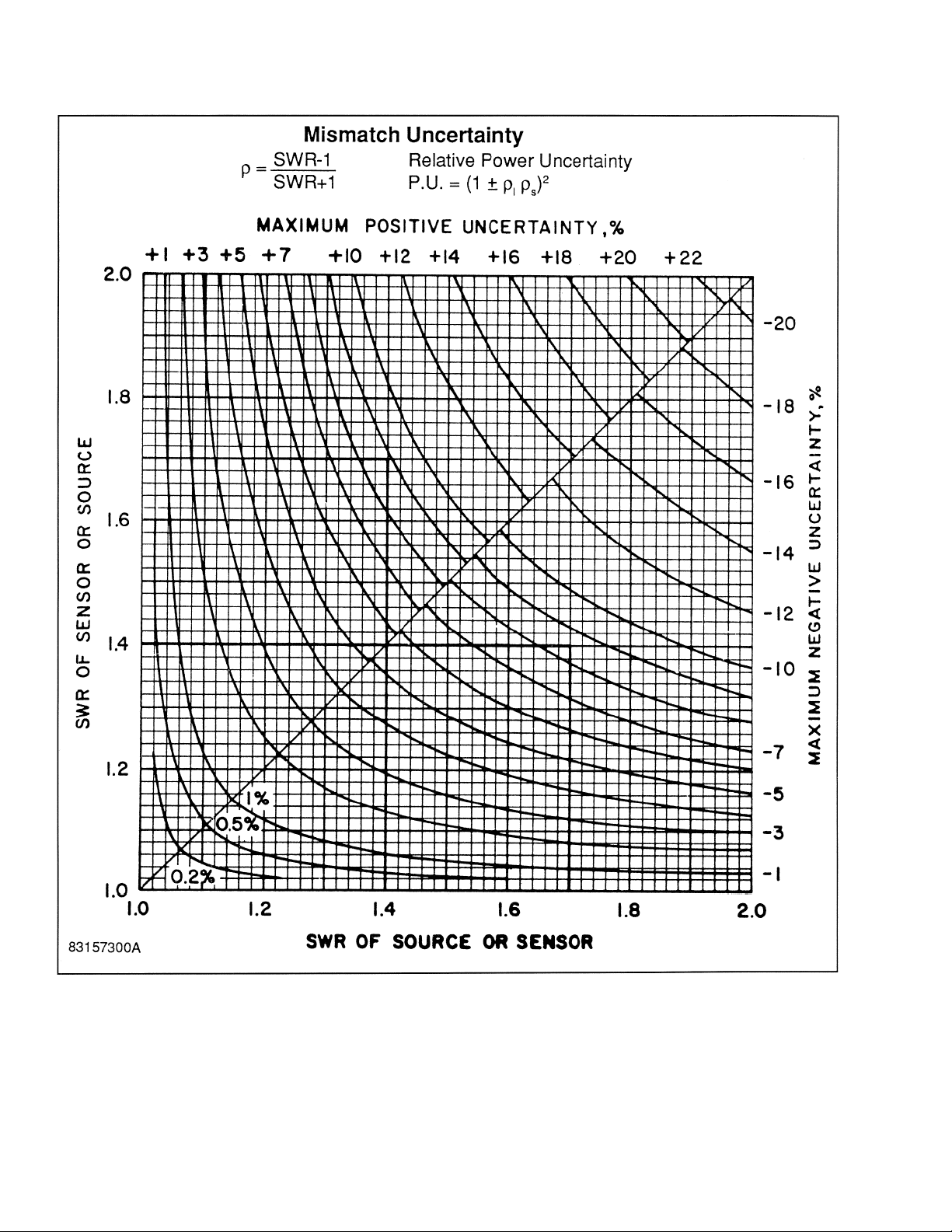
Boonton 4240 Series RF Power Meter
Figure 4-11. Mismatch Uncertainties Chart
4.8 Waveform Sensitivity
Thermal sensors are insensitive to the waveform because they average RF power over many tens of milliseconds. Modulated
signals, non-sinusoidal waveforms, and even pulses can be detected without distortion of the measurement. Thermal sensors
are referred to as RMS responding.
4-12
Operation
Page 59
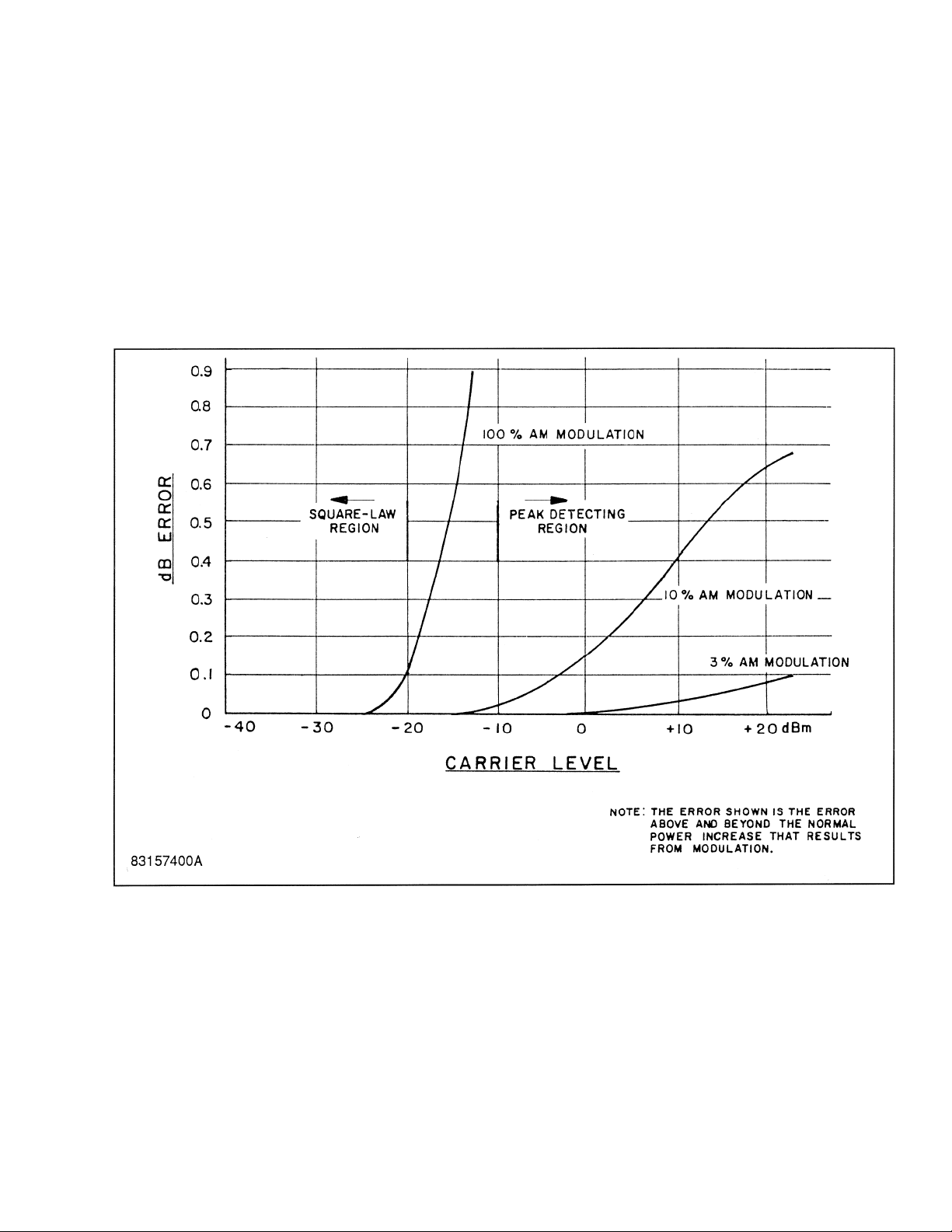
Boonton 4240 Series RF Power Meter
Diode 20 dBm (-10 dBm and 0 dBm for attenuated models 51015 and
sensors are also RMS responding below about -
1033). This response characteristic is obtained because the sensors are dual diode types, and diodes respond in square-law
5
fashion at low and medium levels. This is
that the diodes do not turn on and off a
e diodes have a finite conductance, and this conductance is modulated on a cycle by cycle basis to give a net DC offset
th
proportional to the power.
The square-law res
effect on the measured power at low levels. Of course, frequency modulated and phase modulated signals can be measured at
any level, since the envelope of these modulated signals is flat. Frequency shift keyed (FSK) and quadrature modulated
signals also have flat envelopes and can be measured at any power level.
ponse can be seen in Figure 4-12, where a 100% amplitude modulated signal is shown to have virtually no
not an approximation, but rather an inherent effect. This effect results from the fact
s switches, but behave as signal dependent resistors instead. Even with no signal input,
Figure 4-1 Modulation (5102. Error Due to AM 13 Diode Sensor)
t higher power levels (above approximatel Bm for the 51013 sensor), the diodes operate as peakA
odel 4 0 is so lculate the RF
M 24 ftware calibrated to ca power based on a shaping transfer function (RF to DC) for each sensor
pe. Ho ever, o RF si nals wi
region and in the tr
vel power of the pulse (pulse power) is to be mle
HANNELS menu. For example, if the signal consists of pulses with a duty cycle of 25%, set DUTY to 25. This will add 6
C
B to the displayed power and turn on the "Pk" indicator following the units.
d
y measurements f e valid in this ty w nl o g th flat envelopes (CW, FM, PM, FSK, quadrature, etc.) ar
ansition region from -20 dBm to -10 dBm.
y -10 d detectors. The
r pulses where the duty cycle (on-time percentage) is known andA special provision is made for the case of rectangula
easured. The duty cycle in percent is set into the DUTY entry in the
Operation
the top
4-13
Page 60

Boonton 4240 Series RF Power Meter
nly the display is affected by the duty cycle calculation. The m
O
above. For thermal sensor no correction is needed for level. However, pulse
result in unstable readings becaus o u raging. If the filter time constant is too short, it can
f the AVG function.
o
For diode sensors, the RMS power region extends up to -30 dBm with a gradual change to peak voltage respons
ccurate pulse power measurement, the power meter should read an average power of -30 dBm or less. This is the power
a
indication when the duty cycle is set to 100%. Somewhat useful measurements can be made up to -20 dBm average power,
but the uncertainty will typically b
Extra care should be taken when
uty cycle have a very large pea
d
power, but the peak signal at the sensor diode or thermal element may easily exceed the maximum ratings.
f inadeq ate ave be increased by use
e
e at least +
using the pulse power feature to avoid overload damage to power sensors. Pulses with small
k to average power ratio. The average responding power meter may have a small indicated
1dB.
4.9 Chart Recorder Operation
The chart recorder output is a DC voltage from 0 to 10 volts. In the Watts mode, t
d
isplayed on the main data display divided by 1100 times 10. In the dBm or dBr modes, the output voltage is directly
proportional to the ratio of the d
sensor times 10. For example if
dBm the corresponding Recorder Output voltage would be: (0 – (-75) * 10) / (23 – (-75)) = 750 / 98 = 7.65 volts. The
sensitivity over a 10 dB range would be (10 * 10) / 98 = 1.02 volts. Refer to Section 3.3.2 Sensor Key to locate the upper and
lower limits of the sensor in use in determining the expected Recorder Ouput response.
The output impedance is 9.06 kilohms, which gives the user the option of loading it with 1 kilohm, thereby reducing the full
scale output to 1 volt. The normal 12-bit resolution is still maintained with this method. With a 1 megohm load, the circuit is
essentially open and the error is small. Absolute accuracy is +
ifference of the measured value and the sonsor’s lower limit to the full dynamic range of the
the default upper limit is 23 dB and the lower limit is -75 dB for a particular sensor then at 0
4.10 Bar Graph Operation
The meter presents the power proportionally in the following manner.
tts Mode. The m
Wa
re
sulting in a 1% resolution. A main data display of 1100.0 µW drives the meter to 100 percent of full scale while a display
of 561.0 µW drives the meter to 51 percent of full scale
dBm Mode. The meter follows the digital display as a percentage of the full scale. The bar graph consists of 100 segments
resulting in a resolution of 0.1 dB/segment. A main data display of 0.00 dBm (or any 10 dB increment) drives the bar graph
to zero percent of full scale while 5.00 dBm and 9.99 dBm drives the meter to 45 percent and 90 percent of full scale
respectively. A value of –7 dBm would drive the meter to 27 percent of full scale while a value of –2 dBm would drive the
meter to 72 percent of full scale.
dBr Mode. Selecting the dBr mode positions the bar graph to 50 percent of full scale when the digital d
The analog meter thereafter reads 100 percent of full scale at +5 dBr or more and zero percent of full scale
eter follows the digital display as a percentage of the full scale. The bar graph consists of 100 segments
. The meter reads full scale at 10 dB increments.
easurement process is subject to the same criteria discussed
periods on the order of tens of milliseconds may
e. For
he output voltage is equal to the digits
5%.
isplay reads 0 dBr.
at –5 dBr or less.
4-14
Operation
Page 61

Boonton 4240 Series RF Power Meter
5. Remote Operation
5.1 GPIB Configuration
The 4240 GPIB interface is configured using the Menu > SETUP > IEEE menu. The primary listen/talk address (MLTA) can
be set to any value from 1 to 30 inclusive. The value assigned must be unique to each GPIB device. Secondary address is
not implemented.
Tcho inform the instrument that a message has been completed, the bus controller must end all messages with a terminating
aracter and/or EOI control signal. The Model 4240 can be programmed for several combinations of terminating characters
as required by the controller employed. Selection of termin
menu. There the instrument can be programmed for individual end of string characters in both listener and talker modes as
well as independently enabling the end or initiate control signal.
5.2 RS-232 Configuration
RS-232 interface is also available on the Model 4240. The command set and data transfer protocol are nearly identical to
those for IEEE. The Menu > SETUP > RS232 commands are used to configure the RS-232 interface to comply with the
terminal in use. Setting the end-of-string character and SRQ Mask is accomplished by using the EOS Talker/Listener and
SRQ Mask commands respectively.
ntering the Remote Mode. The Model 4240 enters the remote mode when the ASCII "SI" character (hexadecimal
E
0F/CTRL O) is received. In the remote state, the front pa
the return to local function. The display will show the REM indicator on the last line and enable the TLK, LSN and SRQ as
appropriate.
Returning to Local Mode. The instrument will return to the local state when; a) The <Menu> key is pressed or b) The
ASCII "SO" character (hexadecimal 0E/CTRL N) is received.
Note The instrument must be placed i
store data in the local state for execution in the remote state.
alk Operations. The Model 4240 can be requested to talk in two ways. The "??" mnemonic is available for requesting data
T
via the RS-232 port. Immediately after rec
current talk mode. For example, the follow
the associated units (4230 IEEE Emulation mode):
O (CTRL O/hexadecimal 0F) REM displayed on bottom line, indicating remote operation.
DB TM1 ??<ENTER> Set measurement to dBm, set the talk mode to 1 (talk measurement with units).
Data returned: “0,-3.00 dBm” - indicating no error at -3 dBm.
Note <ENTER> means transmit end-of-string as defined via the Menu > SETUP > RS232 > EOS LSTN
parameter (typically CR).
Terminal Sends Model 4240 Response
n the remote state for it to respond to data messages. It is not possible to
eiving this mnemonic, the instrument responds by transmitting data based on the
ing interactive sequence causes the Model 4240 to transmit the measurement with
ating characters is accomplished via the Menu > SETUP > IEEE
nel keyboard is disabled, except for the <Menu> key which serves as
Remote Operation
5-1
Page 62

Boonton 4240 Series RF Power Meter
Additionally, the ASCII "DC2" character (hexadecimal 12/CTRL R) will cause the instrument to immediately transmit data
base Continuing the ab
d on the current talk mode. ove example:
ER>
R/hexadecimal 12) .
The nd data strings are the sam form and data
strin itive.
R (CTRL Talk the error flag and the measurement in floating point notation
rules for number a e as for the IEEE-488 interface. Number formats are free
gs are case insens
Terminal Sends Model 4240 Response
TM0 <ENT Set the talk mode to send Floating Point Measurements.
5.3 SCPI Language
The mote standard SCPI
4240 Series instruments may be re ly controlled using commands that follow the industry-
rogramming conventions. The default language is:
p
SYSTem:LANGuage SCPI
ll of the functions of the 4240 Series are accessible remotely via SCPI commands.
A
5.3.1 SCPI Structure
he SCP mand nodes”. Each node may contain
T I instrument model defines a hierarchical command structure based on “com
mands xt-level command node. rmed of a series of keywords joined together, and
com or names of a ne Each command is fo
elimited racter. The command be e “root node”, and traverses downwards through
d by a colon “:” cha gins with a colon at th
the command tree to form a s structure is very simi
begins at the root level (“:”), and eac I subsystem) may cont
level directories. To execute an nd, the entire comman
although there are several shor e the command
Data returned: “0,-3.00” - indicating no error and the power is -3
specific command. Thi lar to a DOS file system, where the file system
h directory (SCP ain a list of files (SCPI commands) and lower-
individual comma d name (“path”) must generally be speficied,
tcuts available to reduc string length.
dBm.
CPI su i andard provides a number of
S bsystems or command groups are usually al gned with instrument functions, and the st
-define be used for most in ple, the top level SENSe subsystem groups
pre d subsystems that can strument types. For exam
omman ensing signals (de igitization, linearization), while the OUTPut
c ds that are related to s tection, amplification, d
bsyste tput fu output or controlling an RF
su m contains commands that control ou nctions of the instrument such as voltage
rence
refe output.
5.3.2 Long and Short Form Keywords
Each command or subsystem may be represented by rd, or a short form of that keyword. The short form
is typically the first several characters of the full name, although this is not necessarily the case. The short form of each
keyword is identified in this manual by the keyword characters shown in UPPERCASE, while the long form will be shown in
mixed case. For example, the short form of “CALCulate” is “calc”, while the long form is “calculate”. Long form and short
form commands may be used interchangeably, but only the exact
not be recognized. Sending “CALCUL” will cause an error.
Note that not all keywords have long forms – in this case, the entire keyword will be shown in uppercase.
While uppercase and lowercase text is used to identify keywords, SCPI is generally case-insensitive, so it is acceptable to
send uppercase, lowercase or mixed case keywords to the instrument. The only exception is when a command accept
literal string argument. In this case, quotes may be used to delimit a string of user-defined case.
either its full keywo
forms are permitted – intermediate length commands will
s a
5.3.3 Subsystem Numeric Suffixes
Certain subsys ms, such a the SE or CALCulate subsystems in the 4240 Series, often exist as more than one instance
(often called a “channel” in an instrument). In this case, an optional numeric suffix may be used to define the channel. If this
te s NSe
5-2
Remote Operation
Page 63

Boonton 4240 Series RF Power Meter
suffix is not present, the default channel is assumed.
strument’s “Channel 1” measurement path, while SENS
in
For example, SENSe or SENSe1 defines operation affecting the
e2 commands will apply to channel 2.
.3.4 Colon Keyword Separators 5
The colon (“:”) character is us milar to the way a slash or backslash is used i
with a colon resets parsing at ommand level, and a colon must separate each
new line always resets parsing t he root level, so the leading colon is option
ne.
li
ed si n a filesystem. Prefixing a command string
the root c keyword in the command. Beginning a
o t al if the command is the first command on a
5.3.5 Command Arguments and Queries
Many commands require arguments. In this case, the entire command string is sent, followed by the argument. A space is
used to separate the command from th
orrectio a va If a command requires more than one numeric
c n to lue of 25.0. Arguments may be numeric, or alphanumeric.
rgumen e arg d list.
a t, th uments must be sent as a comma delimite
o read curre rameter, the Query Form of its command may be used. A command query is
T the nt value of a particular pa
rmed ppen ) suffix to the command instead of an argument list. There should not be any
fo by a ding a question-mark (“?”
whitespace betwe For example, “SENSe:CORRection:DCYCle?” queries the duty cycle
correction parame t value.
en the command and the suffix.
ter, and causes the instrument to return its curren
e argument. For example, “SENSe:CORRection:DCYCle 25.0” sets duty cycle
5.3.6 Semicolon Command Separators
The semicolon (“;”) character is used to separate multiple commands on a single line. However, the parsing path is affected
when more than one command is combine
the root level whether or not the command is prefixed by a colon. However, for the second and succeeding commands, the
to
arsing level is NOT reset to the root level, but rather referenced from the current node. This allows the parser to remain at
p
the current node, and execute ot
llowing multi-command strings are equivalent:
fo
:SENSe:CORRection:DCYCle 25.0; :SENSe:CORRection:CALFactor 2.12; (two full-path commands)
:SENSe:CORRection:DCYCle 25.0; CALFactor 2.12; ( second command referenced to CORRection node)
SENSe:CORRection:DCYCle 25.0; CALFactor 2.12; (leading colon omitted from first command)
If a command does not belong to the same subsystem as the preceding command on the same line, then its full path must be
specified, including the colon prefix.
her commands from that node without resending the entire node string. For example, the
d on a line. As noted previously, the first command of a line is always referenced
5.3.7 Command Terminators
All SCPI command strings transmitted to the instrument must be terminated. For commands sent via the GPIB bus, any
character with the IEEE488 EOI (End-Or-Identify) control line asserted may be used as a terminator. This may be the last
letter of the command, query or argument. Optionally, a CR (ASCII 13) and/or LF (ASCII 10) may be included.
For commands sent via the RS-232 interface a CR and/or LF must be included to match the desired protocol.
When the terminating condition is met, the SCPI path is first reset to the root level, and the received message is then passed
to the SCPI parser for evaluation.
5.3.8 4240 Series SCPI Implementa
he SCPI Model of the 4240 provides a single or dual SENSe sub-system to handle sensor input and a matching single or
T
ual CALCulate sub-system to process the data obtained from the sensors into useful results. The CALibration sub-system is
d
d to calibrate power sensors. Channel dependent commands end with a number to indicate the desired channel as follows:
use
tion
Remote Operation
5-3
Page 64

Boonton 4240 Series RF Power Meter
Examples:
:CALCulate:STATe ON Turn on measurement channel 1 (default channel number)
:CALCulate1:STATe ON Turn on measurement channel 1 (specified channel number)
:CALC:STAT
:CALC1:STAT ON
:CALCulate:STATe? Query the state of measurement channel 1 (default chan #)
:CALC:STAT? Query the state of channel 1 (short form, default chan #)
:CALCulate1:STATe? Query the state of measurement channel 1 (specified chan #)
:CALC1:STAT? Query the state of channel 1 (short form, specified chan #)
:SENSe:CORRe n:OFFSet 0.42 Set channel 1 offset correction to 0.42 dB (chan units dBm)
In the discussion and table sed:
Command name long and short f
Default chann : CALibration:AUTO
Explicit channel 1
Select channel 2:
Short Form:
Optional command name in brackets: SYSTem:ERRor[:NEXT]?
Command with channel dependence: CALCulate[1|2]:STATe OFF
ON Turn on measurement channel 1 (short form, default chan #)
Turn on measurement channel 1 (short form, specified chan #)
ctio
s below, the following notation will be u
orm: SYSTem
el 1
: CALibration1:AUTO
CALibration2:AUTO
CAL2:AUTO
Command which
Same comm query:
Command with teral text argument: CA
Command with query form only: FETCh1:CW:POWer?
Square brackets [ ] are used to enclose the list of valid channels for a command, or a list of command options separated by
the vertical separator bar | character. This character is for syntax only, and is not to be entered as part of the command. By
default, if no channel number is specified, Channel 1 is selected.
A literal argument denoted by <character data> indicates a word or series of cha racters, which must exactly match one of
the choices for the command. An argument denoted by <numeric value> requires a string which, when converted to a
number, is within the range of valid arguments. Numerical valu es can generally be in any common form including decimal
and scientific notation. <Boolean> indicates an argument which must be either true or false. Boolean arguments are
represented by the values 0 or OFF for false, and 1 or ON for true. Queries of Boolean parameters always return 0 or 1.
Curly braces { } are used to enclose two or more possible choices for a mandatory entry, separated by the comma character.
One of the enclosed options MUST be inserted into the command, and the braces are not to be entered as part of the
command.
Command with no query form: *CLS
takes numeric argument: SENSe1:AVERage <numeric value>
and; SENSe1:AVERage?
li LCulate1:UNIT s <ch aracter data>
SYNTAX NOTES
5-4
Remote Operation
Page 65

Boonton 4240 Series RF Power Meter
5.4 Basic Measurement Information
e easiest a
Th way to obtain reading is by use of the MEASure command. This command initiates one complete measurement
sequence which includes a
default configuration. Examples are:
MEAS1:POWER
F ov he asurement, individual configuration and function commands should be used. Readi
obtained using the FETCh[ ]? command for current data o
R fund en nits as set by the CALCulate[1|2]:UNIT command. Each reading is preceded by a eadings are in am tal u
ode, which has fol ng
c the lowi meaning:
M urem t is STOPPED. V rned is not updated.
E r retu Measurem
W
INITiate
enabled by INITiate:CONTinuous ON.
MEAS1:VOLTAGE? To return the average voltage of channel 1.
or finer control er t me ngs are
-1 eas en alue retu
0 rro rn. ent is not valid.
1 Normal return. No error.
2 r-range c
3 An Ov -range condition exists.
ith the INITiate:CONTinuous OFF condition, a single measurement cycle is started by use of the
[:IMMEDIATE] command, where bracketed commands are optional. Multiple triggered measurement cycles are
An Unde ondition exists.
? To return the average power of channel 1, or
r the READ[ ]? command for fresh data.
condition
er
5.4.1 Service Request
quests provide eans to signal the host that a particulService re
ervice requests are controlled by the Status Byte Register and the Service Request Enable Register. The Service Request
S
nable Register is a bit mask that determines which summary bits of the Status Byte Register can cause a request for service
E
to be sen
event dr fi
S egister and th uestionable Status Register. These two registers are similar to the Standard Event Status Register
but have the additional ca
bits are not only selected
transition, can be specified
T us Byte is the *ST
query. The Standard Event Status Regist
command or read by the *ESE? Command.
The Operation Status Register is read by the STATus:OPERation:CONDition? command. The transition masks are set by
the STATus:OPERation: Transition and STATus:OPERation:PTransition commands. The bit enable mask is set by the
STATus
Register ATus:OPERation:
T stionable Even tatus Register has the same structure as the Operation Status Register. Refer to the command
descriptions that follow fo
t to the Controller. The summary bits of the Status Byte are the MAV, or Message Available bit, and three bits from
iven registers. The rst of these is the Standard Event Status Register. The bits of this register are set and latched by
tatus R e Q
he Stat read by B? command. The bit enable mask is set by the *SRE command and read by the *SRE?
:OPERation:ENABle command and read by the STATus:OPERation:ENABle? query. The Operation Event
is read by the ST EVENt? query.
he Que t S
a m ar event or group of events have occurred in the instrument.
the
inspecific events within strument and cleared when the register is read. The remaining two registers are the Operation
pability to detect changes in the individual bits of the associated register’s condition register. The
by a mask register, but a change in a selected bit, either a high to low, low to high or either
by transition mask registers.
er is read by the *ESR? Command and the bit enable mask is set by the *ESE
N
r detailed information.
Remote Operation
5-5
Page 66

Boonton 4240 Series RF Power Meter
5.5 SCPI Command Reference
This section contains a list of all SCPI remo
r IEEE
o 488.2 function, and includes a detailed description of each command.
.5.1 IEEE 488.2 Commands
5
he purpose of IEEE488.2 commands is to provide management and data communication instructions for the system by
T
g a set of “*” commands (an asterisk followed by a three character code). These commands allow device control and
definin
status m th
*CLS
Description:
Syntax: *CLS
Argument: None
onitoring, and are e basis for some of the commands of the SCPI STATus subsystem (see Section 5.5.12).
Clear Status command. This command resets the SCPI status registers (Questionable Status and
Operation Status), the error queue, the IEEE488.2 Status Byte (STB) and Standard Event Status
(ESR) registers, and the mea
te commands accepted by the 4240 Series. The list is grouped by SCPI subsystem
surement.
*ESE
Description: Set or return the Standard Event Status Enable Register. The mask value in this register is used to
enable bits of the Standard Event Status Register that are or’ed together to form the ESB summary
bit in the instrument Status Byte. When a mask bit is set, and the corresponding ESR bit goes
true, an SRQ will be generated, provided the Event Status Summary bit (ESB, bit 5) is enabled in
the SRE register. No SRQ can be generated for that condition if the mask bit is cleared. To clear
the entire Standard Event Status Enable Register, send *ESE = 0. See the *ESR command for bit
assignments. This register is not cleared by *CLS, *RST or DCLR.
Syntax: *ESE <numeric value>
Argument: <numeric value> = 0 to 255
5-6
Remote Operation
Page 67

Boonton 4240 Series RF Power Meter
*ESR?
Description: Return the current value of the Standard Event Status Register, then clear the register. This register
has bits assigned to a number of possible events or conditions of the instrument. When the event
occurs, the corresponding bit is latched. The register value is read using this command.
Individual bits may be enabled or disabled for SRQ generation using the ESE mask (see *ESE
command). The following table shows the bit assignments in the Standard Event Status Register:
Bit Value Definition
0 1 Operation Complete Flag 1 = all current operations have completed execution.
1 2 Not used
2 4 Not used
6 64 Not used s returns 0
7 128 Not used alw s returns 0
Syntax: *ESR?
Returns: Current Value of Event Status Register (0 to 255)
*IDN?
Description: Return the instrument identification string. This string contains the manufacturer, model number,
serial number and firmware version number.
Syntax:
Returns: < Mfgr,
*IDN?
lways 4 16 Not used a returns 0
= a r
1 5 32 Command Error emote interface command error exists.
alway
ay
Model#, Serial#, Version# >
.
r 3 8 Device Dependent Error 1 = the instrument encountered a device dependent erro
PC
*O
Syntax: *OPC
Argument: None
*O
Description:
Syntax: *OPC?
Returns: Always returns 1
Description: Clears the OPC (Operation Complete) status flag. This command is issued before the command to
be checked for completion. After this, the flag may be queried by *OPC? until a value of one is
returned, indicating the command has completed. Note that the query is not a true query - a value
of zero wi
PC?
This command examines the OPC (Operation Complete) status flag and returns a “1” if all
pending operatio
ll never be returned.
ns are complete. If pending operations are not yet complete, it does not return.
to indicate operations complete. Otherwise, does not return.
Remote Operation
5-7
Page 68

Boonton 4240 Series RF Power Meter
*OPT?
Description: Return the status of Channel 1 and Channel 2 followed by a list of installed options.
Syntax: *OPT?
Returns: <f1, f2, f3, f4, opt1, opt2, …> : f1 – Chan 1 installed?, f2 – Chan1 sensor present?, f3 – Chan 2
installed?, f4 – Chan 2 sensor present?, opt1, opt2, etc. (option list may be empty).
*RST
Description: Set the instrument to a known “default” configuration. Set measurements to STOP. Set the sensor
temperature offs
internal Calibrato
not changed. Instrument measurement function
Initialized Parameters).
Syntax: *RST
gument: None Ar
et flag to FALSE, set the SCPI file over-write permission to FALSE, turn the
r output OFF and clear the error queues. System communication parameters are
s are set their default values (See Table 3-3,
RE
*S
Description: Set or return the mask value in the Service Request Enable Register. This value is used to enable
particular bits for generating a service request (SRQ) over the GPIB when certain conditions exist
in the Status Byte register. When a mask bit in the SRE Register is set, and the correspondi
STB register bit goes true, an SRQ will be generated. No SRQ can be generated for that condition
if the mask bit is clear. The bits in the Status Byte register are g
the logica
assignments.
S *SRE <numeric value>
yntax:
Argument: <numeric value> = 0 to 255
l OR of the enabled bits from other registers. See the *STB command for bit
enerally summary bits, which are
ng
5-8
Remote Operation
Page 69

Boonton 4240 Series RF Power Meter
*STB?
Description: Return the current value of the Status Byte register. This register has bits assigned to a number of
possible events or conditions of the instrument. The register value may be read using this
command, or may be used to generate a service request (SRQ) over the GPIB when certain
conditions exist. Individual bits may be enabled or disabled for SRQ generation using the SRE
mask (see *SRE command). Note that the bits in the Status
bits, which are the logical OR of the enabled bits from other
the bit assignments in the Status Byte regist
er:
Byte register are generally summary
registers. The following table shows
1 2 Not used
3 QUEStionable Status Summary 1 = an enabled QUEStionable condition is true.
4 Message AVailable flag bit 1 = an output message is ready to transmit.
5 32
6 64
7 128 OPERation Status Summary 1 = an enabled OPERation
Syntax: *STB?
RG
*T
Description:
Syntax: *TRG
Bit Value Definition
0 1 Not used
2 4 Error/E
8
16
Event Status Summary 1 = an enabled Event Status condition is true.
MSS Summary Status 1 = at least one other Status Byte bit is true.
Returns: Current Value of Status Byte register (0 to 255)
Simulate the bus trigger command. This command has the same effect as the GPIB command
GET (Group Execute Trigger), except it must be parsed and decoded before the action tak
There is no query form of this command.
Argument: None
vent queue status 1 = there is at least one event in the error queue.
condition is true.
es place.
ST?
*T
Description:
Syntax: *TST
Returns: Error Code
AI
*W
Description: Wait command. This command insures sequential, non-overlapped execution. The 4240 always
Syntax: *WAI
Argument: None
Self-test query. This command initiates a self-test of the instrument, and returns a result code
when complete. The result is zero for no errors, or a signed, 16-bit number if any errors are
detected.
operates in non-overlapped, sequential mode, therefore this command is accepted as valid, but
takes no action.
Remote Operation
5-9
Page 70

Boonton 4240 Series RF Power Meter
5.5.2 CALCulate Subsystem
he CALCulate group of the command subsystem is used to configure post acquisition data processing. Functions in the
T
CALCulate subsystem are used t
ata is used and how it is procd
define op f the CALCulate program
ot mathematical erations, measurement units, and limit monitoring. The numeric suffix o
nemon Culate1 and CALCulate2
ic in the CALCulate commands refers to a processing and display “channel”, that is CALm
presen r meter ALCulate commands generally DO NOT affect the
re t the powe ’s Channel 1 and Channel 2 functions. The C
ata acq rtion of ection 5.5.11 ). In a signal-flow block diagram, the
uisition po the measurement (see the SENSe subsystem, Sd
ALCul ratio lock. Note that CALCulate2 commands will generate an error
C ate block ope ns will follow those of the SENSe b
used w hann
ALCulate:LIMit:CLEar[:IMMediate]
C
Syntax: CALCulate[1|2]:CLEar[:IMMediate]
ith a single c el Model 4241. if
Description: Clear all latched alarms for the selected channel.
o configure the measurement mode and control which portions of the acquired measurement
essed to yield a finished measurement. In addition to measurement mode, CALCulate is used
Argumen None
ALCulate:LIMit:FAIL?
C
Description: Retu
logic
and high-limit latched. Active means that the
Latched means that the limit has b
Syntax: CALCulate[1|2]:LIMit:FAIL? <Boole
<Boolea
C
Returns: <Boolean1> = summary, <Boolean2> = low-limit active, <Boolean3> = high limit active,
ALCulate:LIMit:LOWer[:POWer]
Descriptio Set or return the lower limit power level for th
t:
rns the status of all limit alarms for the specified channel in five flags. The first flag is the
al sum of the remaining four. They are: low-limit active, high-limit active, low-limit latched
een exceeded since the last limit clear command.
an1>, … <Boolean5>
n4> = low-limit latched, <Boolean5> = high-limit latched
n: e selected channel. This limit is used for level
alarms. When the measured average power is below the
on the display to the left of the measured value, and flag
may be accessed using CALCulate:LIMit:FAIL? query and CALCulate:LIMit:CLEAR
commands.
limit is exceeded when the command is executed;
lower limit, a down arrow ▼ will appear
bits are set in the alarm register which
Syntax:
Argument: <numeric value> = -99.99 to +99.99 dBm
CALCulate[1|2]:LIMit:LOWer[:POWer] <numeric value>
5-10
Remote Operation
Page 71

Boonton 4240 Series RF Power Meter
CALCulate:LIMit:UPPer[:POWer]
Description: Set or return the upper limit power level for the selected channel. This limit is used for level
alarms. When the measured average power is above the upper limit, an up arrow ▲ will appear on
the display to the left of the measured v
be accessed using CALCulate:LIMit:FAIL
alue and flag bits are set in the alarm register which may
? query and CALCulate:LIMit:CLEAR commands.
Syntax: CALCulate[1|
C
D Set or return the lower limit alarm system state for the selected ch
Syntax: CALCulate[1|2]:LIMit:LOWer:STATe <Boolea
C late:LIMit:UPPer:STATe
D Set or return the upper limit alarm system state for the selected channel. When the upper alarm
Syntax: CALCulate[1|2]:LIMit:UPPer:STATe <Boolean>
Argument: <Boolean> = { 0, 1, OFF, ON }
Argument: <numeric value> = -99.99 to +99.99 dBm
ALCulate:LIMit:LOWer:STATe
escription: annel. When the lower alarm is
enabled (ON), the measured average power is compared
error flag is set if out of range. When OFF, no action occu
Argument: <Boolean> = { 0, 1, OFF, ON }
ALCu
escription: is
enabled (ON), the measured average power is compared to the preset upper power limit, and
error flag is set if out of range. Whe
2]:LIMit:UPPer[:POWer] <numeric value>
to the preset lower power limit, and the
rs if the power is out of range.
n>
n OFF, no action occurs if the power is out of range.
the
C ALCulate:LIMit[:B
Description: Set or return the combined upper and lower limit alarm system state for the selected channel.
Syntax: CALCulate[1|2]:LIMit:[BOTH]:STATe <Boolean>
Argument: <Boolean> = { 0, 1, OFF, ON }
OTH]:STATe
When alarms are enabled (ON), the measured average power is compared to the preset upper and
lower limits, and the error flags are set
is out of range. A query returns 1 if either the upper or lower lim
forces both upper and lower ON if either is enabled.
if out of range. When OFF, no action occurs if the power
it alarm is enabled. A query
Remote Operation
5-11
Page 72

Boonton 4240 Series RF Power Meter
CALCulate:MATH:ARGA
Description: Set or return the first argument to be used for channel math operations.
Syntax: CALCulate:MATH:ARGA <character data>
Argument: <character data> = { CH1, CH2 }
CALCulate:MATH:ARGB
Description: Set or return the second argument to be used for channel math operations.
Syntax: H:ARGB <character data>
Argument <character data> = { CH1, CH2 }
:
CALCulate:MATH:DATA
Description: Returns the channel math result.
Syntax:
ALCu H:OPE
C late:MAT Rator
C late:MOD
Description: Set or return the channel math operator.
Syntax: CALCulate:MATH:OPERator <character data>
Argument: <character data> = { CH_SUM, CH_DIFF, CH_RAT }
ALCu e
Descriptio Set or return the system remote measurement mode. Th
Syntax: CALCulate:MODe <character data>
Argument: <character data> = { NORMal, FAST, FILTered }
n: ese measurement modes are only available
CALCulate:MAT
?
CALCulate:MATH:DATA?
under bus control. NORMal is the default mode of operation at approximately 20 readings per
second. FAST returns data at over 200 readings per second. FILTered will only return data when
the filter is full. FILTered works best when INITiate:CONTinuous is OFF and a trigger is issued.
In this case the measurement will not be returned until the filter is full. When the instrument is
returned to local the MODE defaults to NORMal.
5-12
Remote Operation
Page 73

Boonton 4240 Series RF Power Meter
CALCulate:REFerence:COLLect
Description: For the selected channel, make the current power the reference level for ratiometric measurements,
replacing the previous reference level.
Syntax:
Argument: None
ALCulate:REFerence:DATA
C
Descriptio
Syntax: CALCulate[1|2]:REFerence:DATA <numeric value>
Argument: <numeric value>
n: For the selected channel, set the power level specified by the argument as the reference level for
CALCulate[1|2]:REFerence:COLLect
ratiometric measurements, replacing the previous reference level.
= -99.99 dBm to +99.99 dBm
CALCulate:REFerence:STATe
Description: For the selected channel, sets or returns the state of the ratiometric measurement mode. The
power or voltage level.
Argument: <Boolean> = { 0, 1, OFF, O
ratiometric mode causes the reading to be expressed relative to a user specified value. The
resulting reading will have units of dBr (dB relative) or percentage depending upon the type of
s disabled, the reading will be restored to express a
Syntax: CALCulate[1|2]:REFerence:STATe <Boolean>
units in use. When the ratiometric mode i
N }, accepts all, returns OFF, ON
ALCulate:STATe
C
Description:
Syntax: CALCulate[1|2]:STATe <Boolean>
Restrictions Only pertains to channel 2 of
C late:UNITs
cter data>
Argument: <character data> = {DBW, DBMW, DBUW, DBNW, WATTS, VOLTS, DBV, DBMV, DBUV,
Argument: <Boolean> = { 0, 1, OFF, ON }, accepts all, returns OFF, ON
ALCu
Description: units for the selected channel. For power sensors, voltage is calculated with
Syntax: CALCulate[1|2]:UNITs <chara
Set or return the measurement state of the selected channel. When ON, the channel performs
measurements; when OFF, the channel is
: the 4242. Channel 1 cannot be individually disabled. 1 is accepted as
the default argument but no action is taken.
Set or return
reference to the sensor input impedan
always return dBr (dB relative) while lin
DBNV}
disabled and no measurements are performed.
ce. Note that for ratiometric results, logarithmic units will
ear units return percent.
Remote Operation
5-13
Page 74

Boonton 4240 Series RF Power Meter
5.5.3 CALibration Subsystem
T
he CALibration group of c
or a l to
sens
applied to n
T
refer to C 2 inp
N t CALibratio mmands will generate an error if used with a single channel Model 4241. Also note that a
th
su
CALibr al
CALibr al
nd the channe which it is connected. Zero offset adjustment can be performed at any time if no RF signal is
the sensor. Li earity calibration requires that the sensor be connected to the instrument’s built-in RF calibrator.
he numeric suffix of the CALibration commands refers to a measurement channel, that is CALibration1 and CALibration2
H1 and CH ut channels, respectively.
ote tha n2 co lthough
ALibra letion of
tion commands do not accept any arguments, all have a query form, which returns a status code upon compC
e zero or calibration process. This allows the user to determine when the process has completed, and whether or not it was
ccessful.
ation:AUTOc
Description: Performs a multi-point sensor gain calibration of the selected sensor with the internal 50 MHz
Syntax: CALibration[1|2]:AUTOcal[?]
Returns: 0 if successful, 1 otherwise (using query form only)
ation:FIXedc
Description: Performs a calibration at a fixed frequency and level. Fixed-cal does provide for automatic control
ommands is used to control automatic zero offset and linearity adjustments to the RF power
calibrator. This procedure calibrates the sensor’s li
dynamic range.
of the internal 50 MHz calibrator setting the ou
calibration. The RF output level of any other source in use must be set to 0 dBm by the user.
Fixed-cal assumes that a valid Zero has already been performed.
nearity at a number of points across its entire
tput level to 0 dBm prior to performing the
Returns: 0 i
C :ZERO
Syntax: CALibration[1|2]:ZERO[?]
Returns: 0 if successful, 1 otherwise (using query form only)
Syntax: CALibration[1|2]:FIXedcal[?]
f successful, 1 otherwise (using query form only)
ALibration
Description: Performs a zero offset null adjustment. The sensor does not need to be connected to any calibrator
for zeroing – the procedure is often performed in-system. However, this command will
the internal calibrator prior to zeroing to avoid the need to perform this step explicitly.
turn off
5-14
Remote Operation
Page 75

Boonton 4240 Series RF Power Meter
5.5.4 DISPlay Subsystem
The DISPlay group of commands is used to control the selection and presentation of measurements.
DISPlay:ACTive[?]
Description: Set or return the active channel for talk commands.
DISPlay:CLEar
Descriptio Clear all data buffers
S DISPlay:CLEar
D
Syntax: DISPlay:ACTive <numeric value>
Argument: <numeric value> = 1 to 2
n: for CH1 and CH2. Clears averaging filters to empty. Does NOT clear errors.
yntax:
ISPlay:LIN:RESolution
Descripti Set or return th
Syntax: DISPlay[1|2]::LIN:RESolution <numeri
Argumen <numeric value> = 3 to 5
on: e display resolution for linear power and voltage readings. The number of
significant digit
measurements retu
t:
s displayed is equal to the argument. This command also sets the resolution of
rned in remote mode.
c value>
DISPlay:LOG:RESolution
Description: Set or return the display resolution for logarithmic pow
decimal places displayed is equal to the argument. Th
measurements returned in remote mode.
Syntax: DISPlay[1|2]::LOG:RESolution <numeric value>
Argument: <numeric value> = 1 to 3
ISPlay:LABel:MODE
D
Description: Turns on/off the user message display mode enabling the user to place text messages on the front
panel display.
Syntax: DISPlay:LABel:MODE <Boolean>
Argument: <Boolean> = { 0, 1, OFF, ON }
Remote Operation
er and voltage readings. The number of
is command also sets the resolution of
5-15
Page 76

DISPlay:LABel:TEXTA
Description: Displays a text message of up to 20 characters in the first label field when Display Label Mode is
Syntax: DISPlay:LABel:TEXTA <alphanumeric value>
Argument: <alphanumeric value> = A to Z, a to z, 0 to 9, ! @ # $ % ^ & * ( ) _ - + = { } [ ] ? / < > : .
DISPlay:LABel:TEXTB
Description: n the second label field when Display Label Mode
Syntax: DISPlay:LABe
Argument: <alphanumeric value> = A to Z, a to z, 0 to 9 ! @ # $ % ^ & * ( ) _ - + = { } [ ] ? / < > : .
Boonton 4240 Series RF Power Meter
enabled.
Displays a text message of up to 20 characters i
is enable
d.
l:TEXTB <alphanumeric value>
DISPlay:LABel:TEXT
Description:
Syntax:
Argument: <alphanumeric value> = A to Z, a to z, 0 to 9 ! @
C
DISPlay
:LABel:TEXTD
Description: Displays a tex
Syntax:
Argument:
Displays a text message of up to 20 characters in the third label field when Display Label Mode is
enabled.
DISPlay:LABel:TEXTC <alphanumeric value>
# $ % ^ & * ( ) _ - + = { } [ ] ? / < > : .
t message of up to 20 characters in the fourth label field when Display Label Mode
abled.
is en
DISPlay:LABel:TEXTD <alphanumeric value>
<alphanumeric value> = A to Z, a to z, 0 to 9 ! @ # $ % ^ & * ( ) _ - + = { } [ ] ? / < > : .
5-16
Remote Operation
Page 77

Boonton 4240 Series RF Power Meter
5.5.5 FETCh Queries
The FETCh? group of queries is used to return specific measurement data from a measurement cycle that has been INITiated
and is complete or free-running. FETCh? performs the data output portion of the measurement. FETCh? does not start a
new measurement, so a series of FETCh? queries may be used to return more than one set of processed measurements from a
complete set of acquired data. FETCh? usually returns the current value of measurements, and should be used anytime free
running data acquisition is taking place (INITiate:CONTinuous ON). If FETCh? is used for single measurements
(INITiate:CONTinuous OFF), no data will be returned until a measurement has been INITiated and is complete.
FETCh:CW:POWer?
Description: Return current average amplitude reading in channel units.
Syntax:
Returns: CC, average power
Where CC is the me
ETCh:KEY?
F
Description:
Syntax: FETCh:KEY?
Returns:
Key Co
Menu 1
Sensor 2
AVG 8
Zero/Cal 16
REF Level 32
Up Arrow 64
FREQ 4
FETCh[1|2]:CW:POWer?
asurement condition code.
Return the key code of the last key depressed; e.g. MENU = 1.
key code
de
Left Arrow 128
Enter 256
Right Arrow 512
Down Arrow 1024
Remote Operation
5-17
Page 78

Boonton 4240 Series RF Power Meter
5.5.6 INITiate and ABORt Commands
The purpose of the INITiate group of commands is to start and control the process of data acquisition once a measurement
has been configured. Depending on settings, the 4240 RF Power Meter may be commanded to begin either a single
measurement (INITiate:CONTinuous OFF) which stops when complete, or enter a “free-run” mode where data acquisition
occurs continuously (INITiate:CONTinuous ON). The ABORt command terminates any opera
e instrument for an INITiate command.
th
BORt
A
Descripti Terminates any measureme
on: nt in progress and resets the state of the trigger system. Note that
ABORt will leave
and forces INITiate:CONTinuous to OFF.
the measurement in a stopped condition with all current measurements cleared,
tion in progress and prepares
Argument: N
IN :CONTin
Syntax: INITiate:CONTinuous <Boolean
Argument: <Boolean> = {
IN
Syntax: ABORt
one
ITiate uous
Description: Set or return the data acquisition mode for single or free-run measurements. If
INITiate:CONTinuous is set to ON, the 4240 immediately begins taking measurements. If set to
OFF, the measurement will begin as soon as the INITiate command is issued, and will stop once
e measurement criteria (averaging, filtering or sample count) has been satisfied. Note that
th
INITiate:IMMediate
ON; however, by convention this situation
ITiate[:IMMediate[:ALL]]
Description: Starts a single measurement cycle when INITiate:CONTinuous is set to OFF. The measurement
will complete once the power has been integrated for the full F
returned until the measurement is co
INITiate:CONTinuous is ON, how
error.
and READ commands are invalid when INITiate:CONTinuous is set to
0, 1, OFF, ON }
does not result in a SCPI error.
>
ILTer time. No reading will be
mplete. This command is not valid when
ever, by convention this situation does not result in a SCPI
Syntax: INITiate[
Restrictions:
Argument: None
INITiate:CONTinuous must be OFF
5-18
:IMMediate[:ALL]]
Remote Operation
Page 79

Boonton 4240 Series RF Power Meter
5.5.7 MEASure Queries
The MEASure group of commands is
the user to trade off fine control of th
where the power meter is configured, a measurement taken, and results returned in one operation. The instrument is set to a
basic, predefined measurement state with little user intervention necessary or possible. Sometimes, more precise control of
measurement is required. In these cases, MEASure? should not be used. Rather, a sequence of configuration commands,
generally from the CALCulate and SENSe groups should be used to set up the instrument for the measurement, then READ?
or FETCH? commands are used to return the desired measurement data in a sp
MEASure:POWer? Description: Return a power measurement in dBm using a default instrument configura
remains stopped after a measurement.
Syntax: Measure[1|2]:POWer?
MEASure:VOLTage
Description: Return average voltage using a d
Returns: CC, Power in dBm
Where CC is the measurement condition code.
?
efault instrument configuration in volts units. Instrument remains
stopped after a measurement.
used to acquire data using a set of high level instructions. They are structured to allow
e measurement process for easy operability. MEASure? provides a complete capability
ecific format.
tion. The instrument
Where
Syntax: MEASure[1|2]:VOLTage?
Returns: CC, Average voltage in linear volts
CC is the measurement condition code.
Remote Operation
5-19
Page 80

Boonton 4240 Series RF Power Meter
5.5.8 MEMory Subsystem
The MEMory group of commands
pplied f pende path. Up to ten configurations may be
su requency de nt offset (FDOF) tables for external devices in the signal
saved, a ency g a stored FDOF table to a particular
measure nel is no NSe subsystem.
M
MEMory
Description: Return sensor AC cal data.
Syntax: MEMory:SNSR[1|2]:CWRG?
Argument: None, query only.
MEMory:SNSR:INFO?
Description: Return the sensor ID and parameter data.
nd two frequ dependent offset tables. Note, however that assignin
ment chan t a MEMory command; it is handled through the SE
EMory:SNSR:CF?
Description: Return the sensor frequency cal-factor table.
Syntax: MEMory:SNSR[1|2]:CF?
Argument: None, query only.
:SNSR:CWRG?
is used to save and recall instrument operating configurations, and to edit and review user-
Syntax: MEMory:SNSR[1|2]:INFO?
Argument: None
MEMory:SYS:LOAD
Description: Recall a previously stored configuration of an instrument setup.
Syntax: MEMory:SYS:LOAD <filename>
Argument: Alphanumeric filename, "USER0" thru "USER10"
MEMory:SYS:STORe
Description: Save the configuration of the current instrument setup.
Syntax: MEMory:SYS:STORe <filename>
Argument: Alphanumeric filename, "USER1" thru "USER10"
5-20
Remote Operation
Page 81

Boonton 4240 Series RF Power Meter
5.5.9 OUTPut Subsystem
The OUTPut group of commands is used to control various outputs of the 4240. These outputs include the internal 50 MHz
calibrator and the Recorder Output. The internal 50 MHz calibrator is primarily used for automatic calibration of power
sensors. Precise level continuous wave (CW) signals can also be sourced by the internal calibrator. OUTPut commands for
the Recorder Output include setting the DC output to the MAXimum or MINimum level or can be forced to any level in
between. Also the Recorder Output can be assigned to either channel 1 or 2.
UTPut:LEVel[:POWer]
O
Syntax: OUTPut:LEVel[:POWer ]< numeric value >
Description: Set or return the power level of the internal 50 MHz calibrator output signal.
Argument: < numeric value > = -60.0 to
UTPut:SIGNal
O
OUTPut:RECorder:FORCe Description: Command sets the output voltage to the argument. Query returns the output voltage previously set
Syntax: OUTPut:RECorder:FORCe <numeric value>
Argument: <numeric value> = 0.000 to + 10.000 V
Description: Set or return the on/off state of the internal 50 MHz output signal.
Syntax: OUTPut:SIGNal <Boolean>
Argument: <Boolean> = { 0, 1, OFF, ON }
by FORCe or causes error -221 “Settings conflict” if the Recorder Ouput has been assigned to a
channel.
+20.0 dBm (0.1dB resolution)
OUTPut:RECorder:MAX
Description: Set or return the recorder output maximum, or full scale (+10.0V) power reference level.
Syntax: OUTPut:RECorder:MAX
Argument: none
OUTPut:RECorder:MIN
Description: Set or return the recorder output minimum, or downscale (0.0V) power reference level.
Syntax: OUTPut:RECorder:MIN
Argument: none
Remote Operation
5-21
Page 82

Boonton 4240 Series RF Power Meter
OUTPut:RECorder:SOURce
Description: Set or return the source channel for the Recorder Output.
Syntax: OUTPut:RECorder:SOURce <character data>
Argument: <character data> = CH1, CH2, ACTIVE
5-22
Remote Operation
Page 83

Boonton 4240 Series RF Power Meter
5.5.10 READ Queries
he purp AD
T ose of the RE ? group of queries is to initiate a measurement cycle, acquire data, and return specific measurement
ata. READ s the
d ? perform initiation, data acquisition, postprocessing, and data output portions of the measurement. READ?
is equivalent to ABORtin
ready. READ? generally
every time it is issued, RE
this case, use FETCh que
SENSe:FILTer) is filled.
READ:CW:POWe
Description: Return current average amplitude reading in channel units.
g any operation in progress, INITiating a new measurement, then FETChing the data when it is
does not return data unless acquisition is complete. Since READ? INITiates a new measurement
AD? queries should not be used for free running data acquisition (INITiate:CONTinuous ON) - in
ries instead. The measurement is generally considered complete when the integration filter (see
r?
Syntax:
Returns: CC, Average power (watts, dBm)
Where CC is the measurement condition code.
READ[1|2]:CW:POWer?
Remote Operation
5-23
Page 84

Boonton 4240 Series RF Power Meter
5.5.11 SENSe Subsystem
The purpose of the SENSe command subsystem is to directly configure device specific settings used to make measurements,
generally parameters related to the RF power sensor and signal processing. The SENSe commands are used to configure the
power meter for acquiring data. SENSe enables you to change measurement parameters such as filtering or averaging,
perating frequency and calfactors, and measurement gain or offset. The numeric suffix of the SENSe program mnemonic in
o
e SENSe commands refers to a hardware measurement “channel”, that is SENSe1 and SENSe2 represent the instrument’s
th
SENSOR 1 and SENSOR 2 signal
nd display portion of the measurement (see the CALCulate subsystem, Section 5.5.2). Note that SENSe2 commands will
a
nerate d w
ge an error if use ith a single channel 4240 Series instrument.
ENSe:CORRe ion:CALFacto
S ct r
ion Se eturn the frequency ca or currently in use on the selected channel. N
Descript : t or r lfact ote setting a
an lied when the op frequency was set, and setting the
paths, respectively. The SENSe commands generally DO NOT affect the data processing
lfactor ll o as calculated
d app erating operating frequency will
erride ing.
nd wi lfactor that wca with this comma verride the “automatic” frequency ca
settov this calfactor
SENSe[1|2]:CORRe ctor <numeric value>
nt: <nu c value> = –3
SENSe:CORRection:DCYCle
Set o turn the duty cycle correction factor currently
SEN 1|2]:COR le
Argumen <numeric value> = 0.01 to 100.00
S
Argumen <numeric value> = 0.01e9 to 110.0e9 Hz (actua
Syntax: ction:CALFa
Argume meri .00 to 3.00 dB
Description: r re in use on the selected channel.
Syntax: Se[ Rection:DCYC
t: percent
ENSe:CORRection:FREQuency
Description: Set
Syntax: SENSe[1|2]:CORRection:FREQuency <numeric value>
t: l sensor may have narrower range)
or return the RF frequency for the current sensor, and apply the appropriate frequency
calfactor from the sensor’s EEPROM table. Application of this calfactor cancels out the effect of
variations in the flatness of the sensor’s frequency response. If an explicit calfactor has been set,
either manually or via the SENSe:CORRection:CALFactor command, entering a new frequency
will override this calfactor and use only the “automatic” frequency calfactor.
SENSe:CORRec
Description: Set or return a measurement offset in dB for the selected sensor. This is used to compensate for
Syntax: SENSe[1|2]:CORRection:OFFSet <numeric value>
Argument: <numeric value> = -99.99 to 99.99 dB
5-24
tion:OFFSet
external couplers, attenuators or amplifiers in the RF signal path ahead of the power sensor.
Remote Operation
Page 85

Boonton 4240 Series RF Power Meter
SENSe:FILTer:STATe
Description: Set or return the current setting of the integration filter on the selected channel. OFF provides no
filtering, and can be used at high signal levels when absolute minimum settling time is required.
ON allows a user-specified integration time, from 50 milliseconds to 20 seconds (see
SENSe:FILTer:TIMe command). Note that setting the filter time will force the state to ON.
AUTO uses a variable amoun
the current signal level to a value
settling time at most levels.
t of filtering, which is set automatically by the power meter based on
that gives a good compromise between measurement noise and
Syntax:
SENSe:FILTer:TIMe
Syntax: SENSe[1|2]:FILTer:TIMe <nu
Argument: <numeric value> = 0.05 to 20.00 s
Argument: <character data> = {OFF, ON, AUTO}
Description: rn the current length of the integration filter on the selected channel. If the filter state is
SENSe[1|2]:FILTer:STATe <character data>
Set or retu
set to AUTO, querying the time will return -0.01, an
Note that setting the filter time will force the state to
meric value>
d if set to OFF, a time query will return 0.00.
ON.
econds in 50 millisecond increments
Remote Operation
5-25
Page 86

Boonton 4240 Series RF Power Meter
5.5.12 STATus Commands
The STATus command subsystem en
amine the status or cont
ex rol status reporting of the power meter by accessing the Device, Operation and Questionable status
roups.
g
STATus:DEVice:CONDition?
Description: turn t lue of the De table shows the bit
signm gister. These nt in real time, and can change
respon ges in the instru
Bit alue Definition
0 1 Not used always returns 0.
1 2 Channel 1 1 = A sensor or pr
2 4 Channel 1 = A sensor or probe is connected to ch
3 8 Channel 1 E 1 = Channel 1 is reporting an error.
5 32 Shape Cal 1 1 = Channel 1 is using a CW sha
7 128 Smart Cal 1 = Channel 1 is u
8 256 Smart Cal 1 = Channel 2 is u
9 512 Auto Cal 1 1 = Channel 1 is u
1 Not used alw
2 40 ways returns 0.
1 96 Not used al
13 92 Key Press
Syntax: STATu
V
10 1024 Auto Cal 2 1 = Channel 2 is u
1 2048 ays returns 0.
81 1 = A key has been pressed.
14 16384 Not used always returns 0.
15 32768 Not used always returns 0.
ables you to control the SCPI defined status reporting structures. The user may
t va llowing Re he curren vice Condition register. The fo
eas ents in the re bits are updated by the instrum
m ondition. in se to chan ent’s operating c
Connected obe is connected to channel 1.
2
Connected annel 2.
rror
l 2 using a CW sha 6 64 Shape Ca 1 = Channel 2 is
1 sing a CW smart cal table.
2 sing a CW smart cal table.
sing an auto cal table.
sing an auto cal table.
s:DEVice:CONDition?
ror. 4 16 Channel 2 Error 1 = Channel 2 is reporting an er
pe cal table.
pe cal table.
Descripti Sets or returns the Device Enable register, which
Argument: <numeric v
Returns: 16-bit register value (0 to 65535)
TATus:DEVice:ENAB
on: contains the bit mask that defines which true
Syntax: STATus:DEVice:ENABle <numeric value>
Returns: 16-bit r
le S
conditions in the Device Status
instrument Status Byte. If any
Event bit is true, the Device Status
alue> = 0 to 65535
egister value (0 to 65535)
Event register will be reported in the Device Summary bit of the
bit is 1 in the Device Enable register and its corresponding Device
summary bit will be set.
5-26
Remote Operation
Page 87

Boonton 4240 Series RF Power Meter
STATus:DEVice:EVENt?
Description: Returns the current contents of the Device Event register then resets the register value to 0. The
Device Event register contains the latched events from the Device Condition register as specified
by the Device status group’s positive and negative transition filters.
Returns: 16-bit register value (0 to 65535)
S
Description: Set or return the v
Syntax:
Syntax: STATus:DEVice:EVENt?
TATus:DEVice:NTRansition
a bit in the ne
the Device Condition register to cause a 1 to be written in the associated bit of the Device Event
register.
STATus:DEVice:NTRansition <numeric value>
alue of the negative transition filter bitmask for the Device status group. Setting
gative transition filter causes a 1 to 0 (negative) transition in the corresponding bit of
Returns: 16-bit register value (0 to 65535)
STATus:DEVice:PTRansition
Description
Syntax:
Argumen <numeric value> = 0
Returns: 16-bit register v
Argument: <numeric value> = 0 to 65535
: Set or return the value of the positive transition filter bitmask for the Device status group. Setting
a bit in the positive transition filter causes a 0 to 1 (positive) transition in the corresponding bit of
the Device Condition register to cause a 1 to be written in the associated bit of the Device Event
register.
STATus:DEVice:PTRansition <numeric value>
t: to 65535
alue (0 to 65535)
Remote Operation
5-27
Page 88

STATus :CO
Description:
:OPERation NDition?
Boonton 4240 Series RF Power Meter
Return the current value of the Operation Condition register. The following table shows the bit
assignments in the register. These bits are updated by the instrument in
in response to chang
es in the instrument’s operating condition.
real time, and can change
Bit Value Definition
0 1 Calibrating 1 = sensor calibration in progress.
1 2 Settling 1 = averaging filter is not fu
2 4 Ranging 1 = range change in progress.
3 8 Not used always returns 0.
4 16 Measuring 1 = measurement in progre
5 32 Triggering 1 = Trigger mode enabled
6 64 Not used always re
7 128 Not used always returns 0.
8 256 Alarm 1 1 = Chann
9 512 Alarm 2 1 = Chann
10 1024 Alarm Latch 1 1 = Channel 1 alarm is lat
11 2048 Alarm Latc 1 = Chann
12 4096 Not used always returns 0
13 8192 Not used always returns 0.
14 16384 Not used always returns 0.
15 32768 Not used always returns 0.
ll.
ss.
waiting for a trigger.
turns 0.
el 1 is in an alarm condition.
el 2 is in an alarm condition.
ched.
h 2 el 2 alarm is latched.
Syntax: STATus:OPERation:CONDition
S :OPERation ABle
Description:
Returns: 16-bit register value (0 to 65535)
TATus :EN
Sets or returns the Operation Enable register, which contains the bit mask that defines which true
conditions in the Operation Status Event register will be reported in the Operation Summary bit of
the instrument Status Byte. If any bit is 1 in the Operation Enable register and its corresponding
Operation Event bit is true, the Operation Status summary b
?
it will be set.
Syntax: STATus:OPERation:ENABle
Argument: <numeric value> = 0 to 65535
STATus:OPERation:EVENt?
Description:
Returns: 16-bit register value (0 to 65535)
Returns the current contents of the Operation Event register then resets the register value to 0. The
Operation Event register contains t
specified by the Operation status g
Syntax: STATus:OPERation:EVENt?
Returns: 16-bit register value (0 to 65535)
5-28
Remote Operation
<numeric value>
he latched events from the Operation Condition register as
roup’s positive and negative transition filters.
Page 89

Boonton 4240 Series RF Power Meter
STATus:OPERation:NTRansition
Description: Set or return the v
Setting a bit in
corresponding bit of the Operation Condition register to cause a 1 to be written in the associated
bit of the Operation Event register.
Syntax:
Argument: <numeric value> = 0 to 65535
STATus:OPERation:NTRansition <numeric value>
alue of the negative transition filter bitmask for the Operation status group.
the negative transition filter causes a 1 to 0 (negative) transition in the
Returns: 16-bit register value (0 to 6553
STATus
Description: Set or return the
Syntax: lue>
t:
STATus:PRESet
Description: Sets SCPI enable registers and
:OPERation:PTRansition
value of the positive transition filter bitmask for the Operation status group.
Setting a bit in
corresponding bit of the Operation Condition register to cause a 1 to be written in the associated
bit of the Operation Event register.
STATus:OPERation:PTRansition <numeric va
Argumen <numeric value> = 0 to 65535
Questionable Enable mask reg
conditions. All bits for the device and questionable calibration registers are enabled. All positive
transition filters are enabled and all negative transition filters are cleared.
the positive transition filter causes a 0 to 1 (positive) transition in the
5)
5) Returns: 16-bit register value (0 to 6553
transition filters to the default state. The Operational Enable and
isters are both cleared so an SRQ will not be generated for these
Syntax:
Argument: None
STATus:PRESet
Remote Operation
5-29
Page 90

Boonton 4240 Series RF Power Meter
STATus:QUEStionable:CONDition?
Description: Return the current value o
bit assignments in the register. These bits are updated by the instrument in real time, and can
change in response to changes in the instrument’s operating condition.
f the Questionable Condition register. The following table shows the
Bit Va
0
2 4 Not used always 0.
3 8 Power 1 = a power measurement may be
4 6 Not used
5 2 Not used
6 4 Not used
10 1024 Not used
12 96 Not used always 0.
13 81
14 16
15 32
Syntax: STATus:QUEStionable:CONDition?
Returns: 16-bit register value (0 to 65535)
S TATus:QUEStionable:ENABle
1
7 128 Not used always 0.
8 256 Calibration 1 = sensor requires calibration and/or zeroing
9 512 Not used always 0.
11 2048 Not used always 0.
lue Definition
1 Not used always 0.
2 Not used always 0.
1 always 0.
3 always 0.
6 always 0.
40
92 Not used always 0.
384 Not used always 0.
768 Not used always 0.
always 0.
invalid.
Description: Sets or returns the Questionable Enable register, which contains the bit mask that defines which
true conditions in the Questionable Status Event register will be reported in the Questionable
Summary bit of the instrument Status Byte. If any bit is 1 in the Questionable Enable register and
its corresponding Questionable Event bit is true, the Questionable
Syntax: STATus:QUEStionable:ENABle <numeric value>
Argument: <numeric value> = 0 to 65535
Returns: 16-bit register value (0 to 65535)
TATus:QUEStionable:EVENt? S
yntax: STATus:QUEStionable:EVENt?
Description: Returns the current contents of the Questionable Event register then resets the register value to 0.
The Questionable Event register contains the latched events from the Questionable Condition
register as specified by the Questionable status group’s positive and negative transition filters.
S
Returns: 16-bit register value (0 to 65535)
Status summary bit will be set.
5-30
Remote Operation
Page 91

Boonton 4240 Series RF Power Meter
STATus:QUEStionable:NTRansition
Description: Set or return the value of the negative transition filter bit mask for the Questionable status group.
Setting a bit in the negative transition filter causes a 1 to 0 (negative) transition in the
corresponding bit of the Questionable Condition register to cause a 1 to be written in the
ciated bit of the Questionable Event register.
asso
Syntax: STATus:QUEStionable:NTRansition <numeric valu
Argument: <numeric value> = 0 to 65535
e>
Returns: 16-bit register value (0 to 65535)
STATus:QUEStionable:PTR
Description: Set or return the value of the positive transition filter bit mask for the Questionable status
Syntax: STATus:QUEStionable:PTRansition <numeric value>
Argument: <numeric value> = 0 to 65535
Returns: 16-bit register value (0
STATus:QUEStionable:CALibration:CONDition
Description: Return the current value of the Questionable Calibration Condition register. This register is used
ansition
Setting a bit in the positive transition filter causes a 0 to 1 (positive) transition
corresponding bit of the Que
associated bit
to notify the user of questionable quality with respect to calibration. The following table shows
the bit assignments in the register. These bits are updated by the instrument in real time, and can
change in resp
of the Questionable Event register.
to 65535)
?
onse to changes in the instrument’s operating condition.
group.
in the
stionable Condition register to cause a 1 to be written in the
Bit lue Definition
0 1 Not Used
1 2 Not used
2 4 Sens1 Default Shape 1 = Channel 1 using default shape table.
Syntax: STATus:QUESti
Returns: 16-bit register value (0 to 65535)
Va
3 8 Sens2 Default Shape 1 = Channel 2 using default shape table.
onable:CALibration:CONDition?
Remote Operation
5-31
Page 92

Boonton 4240 Series RF Power Meter
STATus:QUEStionable:CALibration:ENABle
Description: Sets or returns the Questionable Calibration Enable register, which contains the bit mask that
defines which true conditions in the Questionable
Questionable Calibration Summary bit of the Questio
the Questionable Calibration Enable register and its corresponding Questionable Calibration Event
bit is true, the Questionable Calibration summary bit will be set.
Argument: <numeric value> = 0 to 65535
Returns: 16-bit register value (0 to 65535)
S
Syntax: STATus:QUEStionable:CALibration:ENABle <numeric value>
TATus:QUEStionable:CALibration:EVENt?
Description: Returns the current contents of the Questionable Calibration Event register then resets the register
value to 0. The Questionable Calibration Event regi
Questionable Calibration Condition register as specified by
group’s positive and negative transition filters.
Calibration Event register will be reported in the
nable Condition register. If any bit is 1 in
ster contains the latched events from the
the Questionable Calibration status
Syntax: STATus:QUEStionable
STATus:QUEStionable:CALibration:NTRansition
Syntax: STATus:QUEStio
Argument: <numeric value> = 0 to 65535
Returns: 16-bit register value (0 to 65535)
S
Returns: 16-bit register value (0 to 65535)
Description: Set or return the value of the negative transition filter bit mask for th
status group. Setting a bit in the negative t
corresponding bit of the Questionable Calibration Condition register to cause a 1 to be written in
the associated bit of the Questionable Calibration Event register.
TATus:QUEStionable:CALibration:PTRansition
Description: Set or return the value of the positive transition filter bit mask for the Questionable Calibration
status group. Setting a bit in the positive transition filter causes a 0 to 1 (positive) transition in the
corresponding bit of the Questionable Calibration Condition register to cause a 1 to be written in
the associated bit of the Questionable Calibration Event register.
Syntax: STATus:QUEStionable:CALibration:PTRansition <numeric value>
:CALibration:EVENt?
nable:CALibration:NTRansition <numeric value>
e Questionable Calibration
ransition filter causes a 1 to 0 (negative) transition in the
Argument: <numeric value> = 0 to 65535
Returns: 16-bit register value (0 to 65535)
5-32
Remote Operation
Page 93

Boonton 4240 Series RF Power Meter
5.5.13 SYSTem Subsystem
T Tem group o mmands is used to control system-level functions not directly related to instrument measurement
he SYS f co
perform nce. SYSTem ommands are used to return error codes or messages from the power meter error queue, control
hardware features and con
SYSTem:BEEP[:ENABle]
Description: Set or return the status of the audible keyboard beeper.
a c
figure communication parameters for the GPIB.
SYSTem:BEEP:IMM iate
Description:
Syntax:
Argument: None
S
Syntax: SYSTem:COMMunicate:GPIB:ADDRess <numeric value>
Argument:
S
Syntax: SYSTem:BEEP[:ENABle] <Boolean>
Argument: <Boolean> = { 0, 1, OFF, ON }
ed
Causes the system to emit an audible beep. Command only; does not respond to a query.
SYSTem:BEEP:IMMediate
YSTem:COMMunicate:GPIB:ADDRess
Description: Set
YSTem:COMMunicate:GPIB:EOI
Description: Set or return the status of the GPIB EOI .
or return the GPIB bus address.
<numeric value> = 1 to 30
Syntax:
Argument: <Boolean> = { 0, 1, OFF, ON }
SYSTem:COMMunicate:GPIB:LISTe
Argument:
Description: Set or return the GPIB Listen end-of-string terminator .
Syntax: SYSTem:COMMunicate:GPIB:LISTen <character data>
SYSTem:COMMunicate:GPIB:EOI <Boolean>
n
<character data> = {LF, CR, CRLF, EOIONLY}
Remote Operation
5-33
Page 94

Boonton 4240 Series RF Power Meter
SYSTem:COMMunicate:GPIB:TALK
Description: Set or return the GPIB Talk end-
Syntax: SYSTem:COMMunicate:GPIB:TALK <character data>
Argument: <character data> = {LF, CR, CRLF, EOIONLY}
SYSTem:COMMunicate:SERial:BA
Description: Set or return the RS232 baud rate.
UD
of-string terminator .
Syntax: SYSTem:COMMunicate:SERial:BA
Argument: <numeric value> = 300, 6
SYSTem:COMMunicate:SERial
Description: Set or return the RS232 serial word
Syntax: SYSTem:COMMunicate:SERia
Argument: <numeric value> =
YSTem:COMMunicate:SERial:PARity
S
Description: Set or return the RS232 parity.
Syntax: SYSTem:COMMunicate:SERial:PARity < character data >
Argument: <character data> = ODD, EVEN, NONE
:BITS
00, 1200, 2400, 4800, 9600, 19200, 38400, 57600, 115200
length (Data Bits).
l:BITS <numeric value>
7, 8
YSTem:COMMunicate:SERial:SBITs
S
Description: Set or return the number of RS232 serial stop bits.
UD <numeric value>
5-34
Syntax: SYSTem:COMMunicate:SERial:SBITs <numeric value>
Argument: <numeric value> = 1, 2
Remote Operation
Page 95

Boonton 4240 Series RF Power Meter
SYSTem:ERRor[:NEXT]?
Description: Returns the next queue
error. Note that errors are stored in a “first-in-first-out” queue, so if more than one error has
occurred quence they happened. The action
of readin e most recent error has been read
further queries will report a code of zero, and “No Error”. See Appendix A for detailed
descriptions of the error codes that may be returned.
, repeating this command will report the errors in the se
g an error removes that error from the queue, so once th ,
d error code number followed by a quoted ASCII text string describing the
ED ERROR DESCRIPTION”
SYSTem:ERRor:CODE?
Syntax: SYSTem:ERRor:CODE?
SYSTe
Description: Returns the number of errors that currently exist in the error queue. A value of 0 means that there
Syntax: SYSTem:ERRor[:NEXT]?
Returns: <numeric error code>, “QUOT
Description: Returns the next queued error co are stored in a “first-in-first-out”
queue, so if more than one err s command will report the error codes
in the sequence they happened ror removes that error from the queue,
so once the most recent error has been read, any more queries will report a code of zero. See
Appendix A for a more detaile that may be returned.
Returns: <numeric error code>
m:ERRor:COUNt?
are no errors in the queue. Therefore, either no errors have occurred, or all errors have been read.
See Appendix A for a more det ed.
Syntax: SYSTem:ERRor:COUNt?
de number. Note that errors
or has occurred, repeating thi
. The action of reading an er
d description of the error codes
ailed description of the error codes that may be return
Returns: <numeric error co
SYSTem:PRESet
Description: Set 4240 default parameters. E See Tables 3-2, 3-3
and 3-4 for a l values for each parameter.
Syntax:
Argument: None
SYSTem:PRESet
de>
quivalent to SETUP > RECALL > DEFAULT.
ist of the default
SYSTem:VERSion?
Description: R liance claimed.
Syntax: SYSTem:VERSion?
Returns: <character data> = Version Code as <year.version> YYYY.V (will return 1999.0)
eturn the SCPI version comp
Remote Operation
5-35
Page 96

Boonton 4240 Series RF Power Meter
.5.14 INSTrument:VERSion Commands
5
INSTrument:VERSion grou uery the firmware and FPGA revision codes. The firmware c
follows a “YYYYMMDD” format. The FPGA revisio s a major and minor representation in the form of
MM.mm” where “MM” is the major revision number and “mm” in the minor revision number.
“
INSTrument:VERSion:FIRM
Description: Returns the firmware revision code.
ware?
Returns: YYYYMMDD
IN
Returns: MM.mm
Syntax: INSTrument:VERSion:FIRM
STrument:VERSion:FPGA?
Description: Returns th e. Syntax: INSTrument:VERSion:FPGA?
p of commands is used to q ode
n format ha
ware?
e FPGA revision cod
5-36
Remote Operation
Page 97

Boonton 4240 Series RF Power Meter
.5.15 SCPI Command Summary
5
Table 5-1. SCPI
*CLS Clear Status Command
ESE Set/get Standard Even
* t Status Enable
ESR? Standard Event Status Register Query *
IDN Identification Query *
*OPC Operation Complete Command
*OPC? Operation Complete Query
*OPT? Return the instrument options
*RST Reset Command
*SRE Set/get Service Request Enable
*STB? Read Status Byte Query
*TRG Simulate Group Execute Trigger
*TST? Self-Test Query
BORt to idle
ALCulate[1|2]:LIMit:CLEar[:IMMedC Clear all latched limit alarms
CALculate[1|2]:LIMit:FAI Return the status of all alarms.
CALCulate[1|2]:L Set/return lower limit power level.
CALCulate[1|2]:LIMit[:BOT Set or return the combined upper and lower limit alarm system
CALCulate[1|2]:LIMit:LOWer:STATe Set/return lower limit alarms. <Boolean> = 0, 1, OFF, ON
CALCulate[1|2]:LIMit:UPPer:STATe Set/return upper limit alarms. <Boolean> = 0, 1, OFF, ON
ALCulate[1|2]:LIMit:UPPer[:POWer] ower level.
ALCulate:MATH:ARGA r channel math
C Set or return the first argument to be used fo
IMit:LOWer[:POWer]
L?
H]:STATe
iate]
COMMAND SUMMARY
Immediately set measurement trigger systemA
<Boolean> = {summary, LL, UL, LLL, ULL}
< numeric value > = -99.99 to +99.99 dBm
state for the selected channel.
Set/return upper limit pC
< numeric value > = -99.99 to +99.99 dBm
operations.
Remote Operation
5-37
Page 98

Boonton 4240 Series RF Power Meter
Ta d) ble 5-1. SCPI COMMAND SUMMARY (continue
CALCulate:MATH:ARGB Set or return the second argument to be used for channel math
operations.
CALCulate:MATH:DATA? Returns the channel math result.
ALCulate:MATH:OPERator Set or return the channel math operator.
C
CALCulate:MODE Set/return
CALCulate[1|2]:REFerence:COLLect etric measurement reference
CALCulate[1|2]:REFerence:DATA ent reference level in dBm.
<numeric value> = -99.99 to +99.99 dBm
CALCulate[1|2]:REFerence:STATe
ALCulate[1|2]:STATe Enable currently selected channel allowing measurements to be
C
CALCulate[1|2]:UNITs Change channel units. <character value>
ALibration[1|2]:AUTOcal Start auto calibration with internal calibrator.
C
ALibration[1|2]:FIXedcal Start fixed calibration with internal calibrator.
C
ALibration[1|2]:ZERO Start zero process.
C
ISPlay:ACTive Set/return the active channel for talk commands.
D
ISPlay:CLEar Clear measurement data and display.
D
ISPlay:LIN:RESolution Set number of significant digits for linear displays and remote
D
DISPlay:LOG:RESolution Set number of decimal places for log displays and rem
ISPlay:LABel:MODE Enables/disables the user message display.
D
DISPlay:Label:TEXTA Displays a text message in the first label field.
DISPlay:Label:TEXTB Displays a text message in the second l
<character data> = NORMal, FAST, FILTered
Set the current reading to be the ratiom
level.
Set or return the ratiometric measurem
Set or return the ratiometric measurement mode state.
<Boolean> = 0, 1, OFF, ON
made. <Boolean> = 0, 1, OFF, ON
DBV, DBMV, DBUV
return values. <numeric value> = 3 to 5
values. <numeric value> = 1 to 3
<Boolean> = 0, 1, OFF, ON
<alphanumeric value> = A to Z, a to z, 0 to 9 ! @ # $ % ^ & *
<alphanumeric value> = A to Z, a to z, 0 to 9 ! @ # $ % ^ & *
remote measurement mode
( ) _ - + = { }
( ) _ - + = { } [ ] ? / < > : .
= DBM, Watts, Volts,
ote return
[ ] ? / < > : .
abel field.
5-38
Remote Operation
Page 99

Boonton 4240 Series RF Power Meter
Table 5-1. SCPI COMMAND SUMMARY (continued)
DISPlay:Label:TEXTC Displays a text message in the third label field.
<alphanumeric value> = A to Z, a to z, 0 to 9 ! @ # $ % ^ & *
( ) _ - + = { }
DISPlay:Label:TEXTD Displays a text message in the fourth la
<alphanumeric value> = A to Z, a to z, 0 to 9 ! @ # $ % ^ & *
( ) _ - + = { } [
ETCh[1|2]:CW:POWer? Return current average reading in power units
F
ETCh:KEY? Return code of last key depressed
F
INITiate:CONTinuous ch triggers meas cycles continuously.
INITiate[:IMMediate[:ALL]] ent cycle when trigger event
EASure[1|2]:POWer?
M Return the average power measurement in dBm
MEASure[1|2]:VOLTage? Return the average power measurement in equivalent
EMory[1|2]:SNSR:CF? Return the sensor frequency cal-factor table.
M
EMory[1|2]:SNSR:CWRG?
M Return sensor AC cal data.
EMory[1|2]:SNSR:INFO? Return the sensor ID and parameter data.
M
EMory:SYST:LOAD etup by filename.
M Load saved instrument s
EMory:SYST:STORe
M Save instrument setup by filename.
UTPut:LEVel[:POWer] evel of the internal 50 MHz calibrator
O Set or return the power l
UTPut:SIGNal Set or return the on/off state of the internal 50 MHz output signal.
O
UTPut:RECorder:FORCe Command sets the Recorder Output voltage to the argument.
O
OUTPut:RECorder:MAX Set or return the Recorder Output maxim
OUTPut:RECorder:MIN t minimum, or downscale (0.0V)
OUTPut:RECorder:SOURce for the Recorder Output.
READ[1|2]:CW:POWer? power units.
Set/return state of mode whi
<Boolean> = 0, 1, OFF, ON
Set mode which starts a measurem
occurs
<character data> = "USER0" ... "USER10".
<character data> = "USER1" ... "USER10".
output signal.
<numeric value> = 0.0 to + 10.0 V
power reference level.
Set or return the Recorder Outpu
power reference level
Set or return the source channel
character data> = CH1, CH2, ACTIVE
<
Return new average reading in
[ ] ? / < > : .
bel field.
] ? / < > : .
volts.
um, or full scale (+10.0V)
Remote Operation
5-39
Page 100

Boonton 4240 Series RF Power Meter
5-1. SCPI COMMAND SUMMARY (continued)
SENSe[1|2]:CORRection:CA
SENSe[1|2]:CORRection:DCYCle S
<n
SENSe[1|2]:CORRection:FREQuency Set
SENSe[1|2]:CORRection:OFFSet Set/return sensor offset value in dB.
SENSe[1|2
SENSe[1|2]:FILTer:TIMe
STATus:DEVice:CONDition?
STATus:DEVice:ENABle
STATus:DEVice:EVENt?
STATus:DEVice:NTRansition
STATus:DEVice:PTRansition Set/retur
STATus:OPERation:CONDition? Return value of Operation Condition Register
STATus:OPERation:ENABle
STA O Nt Return value of Operation Ev
STA :O Neg e ion filter
STAT :O n Set/return the Positive Transitio
STATus:PRESet Set device dependen
STATus:QUEStionable:CONDition? Return value of Ques
STATus:QUEStionable:ENABle Set/return value of Questionable Enable Mask
STATus:QUEStionable:EVENt? Return value of Questionable Event Register
STATus:QUEStionable:NTRansition Set/return the negative transition filter
STATus:QUEStionable:PTRansition Set/return the positi
STATus:QUEStionable:CALibration:CONDition? Return value of the question
TATus:QUEStionable:CALibration:ENABle Set/return value of the questionable calibration enable mask
S
]:FILTer:STATe Set/return filter state.
Tus: PERation:EVE ? ent Register
Tus PERation:NTRansition Set/return the ativ Transit
us PERation:PTRa sition n filter
LFactor Set correction factor in dB.
<numeric value> = -3.00 to 3.00
et/return duty cycle correction factor in percent.
umeric value> = 0.0 to 100.0%
channel frequency.
eric value> = 0.01e9 to 110.00e9 Hz
<num
<numeric value> = -99.99 to 99.99
<character data> = OFF, AUTO, ON
Set or return the current length of the integration filter on the
selected channel. <numeric value> = 0.05 to 20.00 seconds
Return value of Device Condition Register
Set/return value of Device Enable Mask
Return value of Device Event Register
Set/return the Negative Transition filter
n the Positive Transition filter
Set/return value of Operation Enable Mask
t SCPI registers to default states
tionable Condition Register
ve transition filter
able calibration condition register
5-40
Remote Operation
 Loading...