

Page 1

P 31
Passive Intermodulation
Analyzer 2 x 20W
Quick Start Guide
Taking performance to a new peak
Page 2
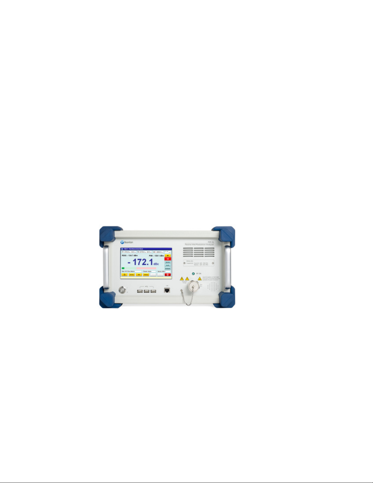
PIM31 Quick Start Guide
The Boonton PIM31 is a high performance instrument that allows users to make
reliable, highly accurate measurements of passive intermodulation, in systems
and components. Read the guide thoroughly before using the instrument to become familiar with its controls, interface and safety concerns.
This document provides a brief summary of the PIM31’s basic operation. For more
detailed information, see the User’s Manual.
Page 3

Safety and Caution Summary
SAFETY:
• INSTRUMENT MUST BE GROUNDED (must be connected to an electrical ground
at the power outlet)
• DO NOT OPERATE THE INSTRUMENT IN AN EXPLOSIVE ATMOSPHERE
• KEEP AWAY FROM LIVE CIRCUITS
• DO NOT SUBSTITUTE PARTS OR MODIFY INSTRUMENT
• NON IONIZING RADIO FREQUENCY RADIATION HAZARD
• ELECTRIC SHOCK HAZARD
CAUTION:
• Please check the power requirements as per the product specifications.
• Ensure at least 2” of clearance around the fan intake on the front panel and
bottom vents.
• Before powering the unit on make sure there are no indications of exposure
to extensive force suck as dents, torn off pieces or loose parts in the case.
• DO NOT touch connectors of components with bare fingers.
• DO NOT switch on RF power without a load or antenna attached.
• DO NOT operate the PIM31 in an active system.
• DO NOT connect or disconnect any component of the test setup with RF power switched on.
• DO NOT operate test system and load without connector savers.
• DO NOT mount components directly on the PIM31.
• DO NOT bend cable tighter than 40 cm / 16” of diameter.
• DO NOT over-torque the RF Port connector and accessories.
• DO NOT use sharp devices on the touch screen.
• To maintain the optimal performance of the PIM31 unit, prevent exposure
to unnecessary force, keep accessories clean and dry, and regularly check for
wear and tear.
PIM31 Series Packing List
The following standard items are included with the unit :
• PIM 31 Series Passive Intermodulation Test System
• Line Cord with 90 degree connector
• USB mouse and USB roll-up keyboard
• 3 connector savers
• Low PIM cable 3m (10ft)
• Low PIM load 50W
• Torque wrench
Page 4

Power up the PIM 31 unit & preparation
Getting Started & Verification
1. Ensure that the main outlet has proper grounding.
2. Switch on the PIM31 main power switch on the backside
of the unit.
3. Wait 5 seconds before switching on front power button.
(This allows time for the protection circuitry to enable all
PIM 31 modules properly).
4. Push Start Button on at the front panel.
The system will boot up automatically and show the user
interface in Field Mode.
The following instructions walk through a basic operation and
functionality tests to verify that the unit is working properly.
1. Mount connector saver to RF Port and Load (if not already mounted)
2. Connect Low PIM cable to the Test system (Note: always
connect the test cable to the instrument first, before
connecting to the DUT)
3. Now the RF Button is visible but inactive. Power levels
and frequencies of the carrier signals must be set in
order to activate the RF button. To do so, pushing the
“Carrier” button displays a list of Carrier signal settings.
Turning off the PIM 31
It is not recommended to power down by “Pulling the plug”
or switching off the Main Switch on the back panel. Follow
the recommended procedure as below:
• Exit the UI by pressing the red exit button. Respond to the
pop-up menu’s choice Yes / No to power the system down.
• Or shut down the unit by simply pressing the power button
on the front panel.
4. Since this is the first boot up, the list is empty.
To enter carrier parameters, push “New” on the Carrier Select screen. Enter a Carrier name, frequencies and
power levels.
Page 5

5. With a growing list of carriers, meaningful carrier names
help to identify the settings: Example 20W_869_896
indicates: power of the signals is 20W, and the frequencies used are 869 MHz and 896MHz.
6. Every entry or change needs to be confirmed by pushing
the “Enter” button. Once entries are complete, return to
the, “Carrier List” by pushing the green Return button.
9. By pressing the RF Button, the system initializes, and
starts measuring PIM.
10. A second push of the RF button stops measurements and
transmission of RF signal carriers. The last PIM reading is
held and shown in grey.
7. Now enter detailed base station or measurement setup
information. Once completed, return to the initial Field
Mode Screen.
8. The selected Site (Test) information is now visible in the
appropriate fields and the RF Button is now active.
11. If satisfied with the results using the provided test cable
and load, the unit may now be used for actual testing.
Verify that RF is OFF and disconnect the test cable and
load.
12. Now connect the end terminal of the system under test
to the RF Port of the PIM 31 and start PIM measurements
from the real system.
Page 6

Wireless Telecom Group Inc.
25 Eastmans Rd
Parsippany, NJ
United States
Tel: +1 973 386 9696
Fax: +1 973 386 9191
www.boonton.com
© Copyright 2010
All rights reserved.
B/PIM31QSG/0610/EN
Note: Specifications, terms and conditions
are subject to change without prior notice.
 Loading...