

Page 1

PIM31 Remote Setup and Operational Procedures
1 Remote Application and TCP/IP Setup
PIM31 Remote Control Panel is the software to control the PIM31 unit from any PC
using a TCP/IP cable connection. This section explains how to setup the PIM31 unit
for TCP/IP from any PC and also the use of the remote application. The software can
be downloaded from the Boonton official website under Products “Manuals & Software”.
1.1 Installation and connection setup for remote control:
1.1.1 Install PIM31 Remote Software
Download the PIM31 Remote Control software from Boonton’s official website
under product’s “Manuals & Software” section
Follow screen instructions during the installation process
Click on “Remote_ctr_V1.2.exe” icon from PC’s desktop to open the software.
1.1.2 Known issues that might occur during installation on Windows OS:
Error message as “Component MSWINSCK.OCX or one of its dependencies not
correctly registered: a file missing or invalid”.
If you do not see this message continue with 9.1.3
Solution:
Search internet or other computers for the missing windows system file
“MSWINSCK.OCX”,
Download and save that file into your PC under any folder
Copy the file into Windows System32 folder
C:/Windows/System32/
Click the executable file “Remote_ctr_V1.2.exe” again
1.1.3 Setting IP address of PIM31
Go to the “Control Panel” of the PIM31’s desktop screen and open the
“Network Connections” icon.
Right click the “Local Area Connection” icon and open the properties window.
Select the “Internet Protocol (TCP/IP)” from the list and enter the IP address in
Page 2
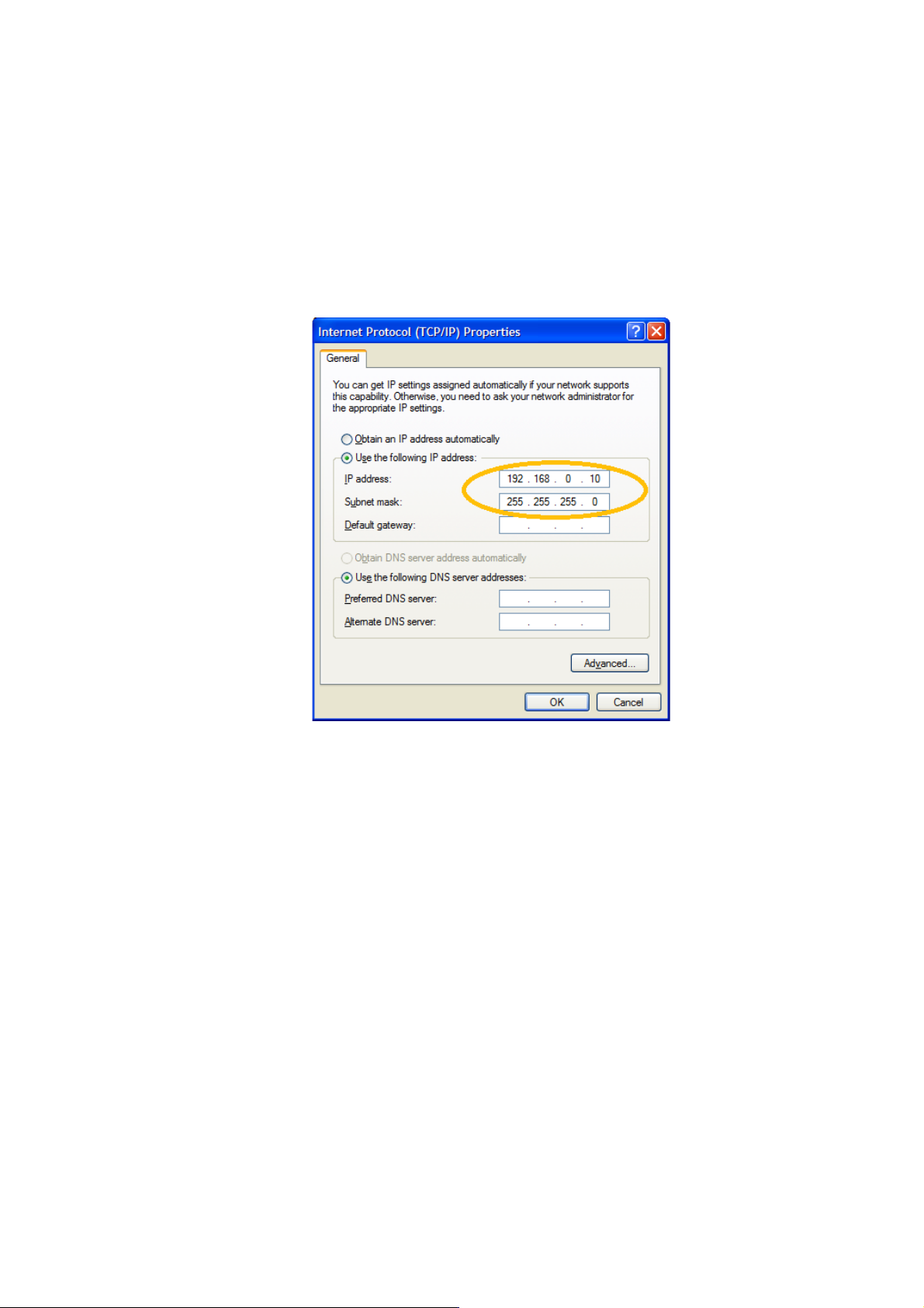
input field.
Check “Use the following IP address”
Enter IP Address: 192.168.0.10 (for example)
(The last number can be any number between 0 and 254 but should be higher
than that of the PC’s IP address)
Subnet Mask: 255.255.255.0
Press OK button when done
1.1.4 Connecting PIM31 and PC.
Connect the PIM31 unit to a PC with a regular LAN cable (not crossed ty pe).
1.1.5 Setting IP Address of PC
Go to “Control Panel”, find & open the “Network Connections” icon.
Right click the “Local Area Connection” and open the properties window.
Select the “Internet Protocol (TCP/IP)” from the list and enter the IP address in
input field.
1. Enter IP Address: 192.168.0.1 (for example)
(the last number should be lower than the same of PIM31 IP address)
2. Enter Subnet Mask: 255.255.255.0
3. Gateway: (Leave it as blank because it does not affect the operation)
Page 3

1.1.6 Check the network connection status of PIM31 and PC
The network connection status for both PIM31 and the PC can be verified by following as below:
a. Tray icon on the status bar.
b. Check the normal status with clicking the network icon.
Note: Connecting PIM31 and PC will disconnect Wireless link of the PC.
Page 4

1.2 Using PIM31 Remote Application:
Before using the remote application the following default settings for both IP
address and port number need to be verified.
1.2.1 Enter IP address and Port
Open the “PIM31 Remote Control” software from desktop
Verify that the IP Address is same as PIM31:
Default : 192.168.0.10
Enter Port 3100
1. Press”Connect” button.
The “Equipment Get” buttons is now enabled
2. With proper connection PIM31 should now show “Remote Control” on its
screen
3. Press “Equipment Get” button.
The model is now shown in the Equipment field and the settings of equipment
are shown as well.
4. Change settings by overwriting the relevant fields and push “Set” button.
5. Pressing “RF ON” activates the RF and measurements are done automatically.
6. “RSSI” can be pushed while RF is off
Page 5

1.2.2 List of remote commands
Below are the lists of remote commands which can be executed remotely either by using Telnet or
HyperTerminal with a regular type of LAN cable connection to the PIM31 unit. It is recommended to
add “\r\n” at the end of each remote command if proprietary applications to execute the following
commands are used. This avoids problems to complete the command executions.
Command
Parameter
Return value
Unit
Description
*IDN?
Product, Model
*RST
F1
Frequency
1,0
MHz
1: True , 0:False(Out of
Range)
F2
Frequency
1,0
MHz
1: True , 0:False(Out of
Range)
P1
Power
1,0
dBm
1: True , 0:False(Out of
Range)
P2
Power
1,0
dBm
1: True , 0:False(Out of
Range)
ON, 1
1,0 1: True , 0:False
ALC
OFF,0
1,0 1: True , 0:False
BW
index
1,0 1: True , 0:False
ON, 1
1,0 1: True , 0:False
SET
RF
OFF,0
1,0 1: True , 0:False
STAtus
F1,F2,P1, P2,
ALC,B W,RF
F1 Frequency
MHz
F2 Frequency
MHz
P1 Power
dBm
P2 Power
dBm
ALC
1,0
BW
index
RF 1,0
ERRor
Last Error
Error Log of Last command
PIM
PIM, Order,
IM Frequency
GET
RSSI
RSSI
 Loading...