


User’s Manual
P 21
Portable Passive
Intermodulation
Test Set
Manual P/N 98405800B
1 / 2010
Taking performance to a new peak

User Manual
Contents
Introduction . . . . . . . . . . . . . . . . . . . . . . . . . . . . . . . . . . . . . . . . . . . . 3
Front Panel Survey . . . . . . . . . . . . . . . . . . . . . . . . . . . . . . . . . . . . . . . 5
Accessories Kit . . . . . . . . . . . . . . . . . . . . . . . . . . . . . . . . . . . . . . . . . . 6
Purpose, Function and Features . . . . . . . . . . . . . . . . . . . . . . . . . . . 8
Purpose . . . . . . . . . . . . . . . . . . . . . . . . . . . . . . . . . . . . . . . . . . . . . . . . 8
Functional Description . . . . . . . . . . . . . . . . . . . . . . . . . . . . . . . . . .10
Features . . . . . . . . . . . . . . . . . . . . . . . . . . . . . . . . . . . . . . . . . . . . . . . 12
Operation Procedure . . . . . . . . . . . . . . . . . . . . . . . . . . . . . . . . . . . .13
Pre Test Checks . . . . . . . . . . . . . . . . . . . . . . . . . . . . . . . . . . . . . . . . .15
PIM Testing Procedures . . . . . . . . . . . . . . . . . . . . . . . . . . . . . . . . . . 17
Advanced Features and Settings . . . . . . . . . . . . . . . . . . . . . . . . .19
Menu Structure . . . . . . . . . . . . . . . . . . . . . . . . . . . . . . . . . . . . . . . . .19
Default Settings . . . . . . . . . . . . . . . . . . . . . . . . . . . . . . . . . . . . . . . . 20
External Connections . . . . . . . . . . . . . . . . . . . . . . . . . . . . . . . . . . . .20
Support . . . . . . . . . . . . . . . . . . . . . . . . . . . . . . . . . . . . . . . . . . . . . . . 21
Specifications . . . . . . . . . . . . . . . . . . . . . . . . . . . . . . . . . . . . . . . . . .22
Version Control . . . . . . . . . . . . . . . . . . . . . . . . . . . . . . . . . . . . . . . . . 23
Types and Figures . . . . . . . . . . . . . . . . . . . . . . . . . . . . . . . . . . . . . .23
Addendum - Data Acquisition Software . . . . . . . . . . . . . . . . . . . . .
2 | PIM 21 User’s Manual

Introduction
Welcome to the Users Manual for the PIM 21 Passive Intermodulation Test Set.
This manual is to inform operators of the PIM 21 of the following:
• Safety Warnings and Safe Operational Procedures
• Equipment purpose, Features and Functional description
• Front Panel controls
• Accessories Kit components
• Operation Procedure and Pre test checks
• PIM Testing procedures
• Advanced Features and Settings
• Maintenance and Support
• Specifications
Safety Warnings
Non Ionizing Radio Frequency Radiation Hazard
This device generates low level Radio Frequency (RF) energy under normal operation, and
should always be operated in accordance with local and national licensing laws. RF energy in
the 800 to 1,000 MHz and 1,800 to 2,200 Mhz regions with a total power no greater than 5
Watts or +37 dBm is present at the test port during testing.
The Test Port is to be terminated into a non radiating 50 ohm load to reduce the risk of RF exposure. Do not operate the “Test / RF On Off” switch on the Test Set if Test Port is open or load
is unknown.
Electric Shock Hazard
The device is supplied with an external 90 to 264 Volt AC power supply for internal battery
charging and general operation for extended periods.
The AC power supply is for indoor use only and is not water resistant, a shock hazard may exist
if operated in wet areas.
Never operate the Test Set with the AC power supply in damp, wet or rainy areas/conditions.
Prior to AC connection always inspect the power cord and case of power supply for damage. If
damage is observed do not use until inspected and repaired by an authorized electrical contractor.
Battery Explosion Hazard
The device contains an internal sealed lead acid battery for portable operation. An explosion
hazard may exist if the battery is incinerated, exposed to extreme temperature (>158°F or
3Boonton

Introduction
+70°C) or charged with excessive voltage. Prior to disposal,
the battery must be removed.
To reduce the hazard from overcharging never exceed the
maximum ‘Ext DC’ voltage of 16 Volts.
As an additional precaution, always remove BATT Fuse, prior
to storage for longer than 4 months.
Transportation Hazard
The device operates by using a transmitted RF Test signal,
which may interfere with navigation and other electronic
systems.
To eliminate the potential of this hazard always remove the
BATT Fuse, prior to transportation by aircraft or near any electronic security systems.
Disclaimer
PIM 21 transmits two CW RF signals with a power of up to 2 W
each to measure passive intermodulation of components and
transmitting systems. PIM 21 test systems are strictly built following customer’s instructions on these measurement frequencies. Wireless Telecom Group and its subsidiaries are under no
circumstances accountable for use of PIM 21 not conforming to
laws and regulations of national and local authorities. Customer
/ user bear the full responsibility and legal accountability to use
PIM 21 only in a lawful manner.
4 | PIM 21 User’s Manual
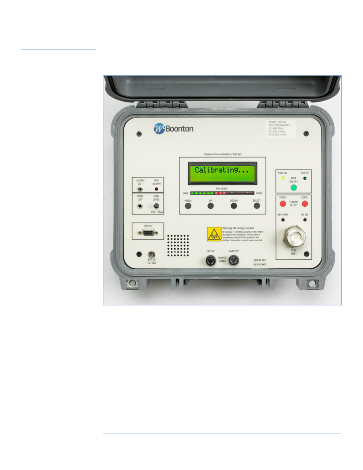
Front Panel Survey
All user controls and connections are made on the front panel of the Test Set.
Some of the control switches have multiple functions, which are explained in detail in the Advanced Features and Settings section of this manual.
5Boonton

Packing Contents
Standard
Accessories Kit
The standard accessories kit provided with the PIM 21 Test Set contains 1 each of
the following items:
57500100A Test Cable
Type N(m) - N(m), 4m (13 ft)
56810400A Power Cord
2m (6 ft)
48000100A Connector Adaptor
⁄”(m) - N(f)
56811400A DC Charging Cable
for Car Accessory Socket
48400700A Power Supply
90 - 264 VAC / 12 VDC, 4 Amp
70047300A Accessories Pouch
95951301A Cable (6 ft) 95951201A RS232 to USB
Converter
95950301A Connector Adaptor
⁄”(f) - ⁄”(f)
95951401A Connector Adaptor
⁄ DIN(F) to N(F)
95950501A Connector Adaptor
N(f) - N(f)
95950101A Low P Cable Load
5 W, N(f) connector
95950401A Connector Adaptor
⁄”(f) - N(m)
6 | PIM 21 User’s Manual

Optional
Accessories kit
95950701A ZB-B11 Test Cable,
⁄”(m)-⁄”(m), 3m (10 ft)
Notes:
For performance and safety reasons use only original qualified components to replace damaged or missing accessory kit items.
Components in the accessories kit are intended for PIM 21 use only however, it is possible to
use the Low IM load, test cable and adaptors for other applications.
Under no circumstances should the Low power PIM sources be used for any other application.
They are designed only for use as a low power intermittent test source, which can be quickly
damaged if used on a continuous basis.
95951001A Torque Wrench
18 ft-lbs
7Boonton

Purpose, Function and Features
Purpose, Function
and Features
Purpose
The PIM 21 is a portable test instrument for the detection of non-linear components and assemblies in radio base station installations.
Non-linear Radio Frequency (RF) assemblies cause Intermodulation Distortion (IM) and the
purpose of the Test Set is to specifically test for this distortion in passive components.
Components such as coax feeder assemblies, filters and antennas all fall into this passive
category, the common term to describe this distortion is Passive Intermodulation Distortion or
PIM.
This tester is designed to aid communications technicians in the field locate components and
assemblies which are creating PIM and degrading the performance of the installation.
The PIM 21 is not intended to be a laboratory instrument or replace such instruments. It has
been specifically designed for field portability and fault location.
Effects Of PIM
A non-linear transfer function is deliberately created in some devices such as mixers. When
two RF frequencies are applied to a mixer other frequencies or products are created. It is the
creation of these additional products which can cause problems in radio base station installations. For example, if the products of two transmitters fall on a receive frequency used at that
installation blocking may occur.
Measurement Theory
All passive RF components have some degree of non-linearity and the function of the PIM 21 is
to evaluate the amount.
Measurement of Passive Intermodulation distortion is typically performed with two excitation
frequencies (RF carriers) and a receiver tuned to the 3rd order IM product.
The frequency of the 3rd order product(s) can be calculated by the following:
IM3 = (2 x F1) – F2 or (2 x F2) – F1
Where IM3 = 3rd order product
F1 = First carrier frequency
F2 = Second carrier frequency
Results can be reported as absolute power measurement (-dBm) from the 3rd order receiver or
as a difference between the excitation carrier power and the receiver measured power (-dBc).
For all test cases the excitation carrier powers must be noted as this will affect the measured
PIM result.
8 | PIM 21 User’s Manual

The PIM 21 is a low power tester with excitation carrier powers up to +30/+33* dBm each. Its
minimum size, reliability, and battery operation, all provide true portability.
To test individual components, bench PIM test systems typically use a power of up to 20W per
carrier. Such systems are heavy and bulky, and are generally considered impractical for field
testing, especially at the mast head.
Measurements between 20W bench sets and 2W portable field sets show predictably some
what different readings. This does not at all diminish the value of the low power measurement.
In theory, a 3rd order IM product will increase by 3 dB for every 1 dB increase in carrier power,
however in practice increases are very much dependent on test conditions and are considerably
lower than the theoretical 3 dB per 1 dB change in power. This is believed to be due to the fact
that poor or corroded connections act much like a diode, and become abruptly non-linear when
sufficient current excites them. This current is usually very low so the PIM 21’s output power is
usually adequate.
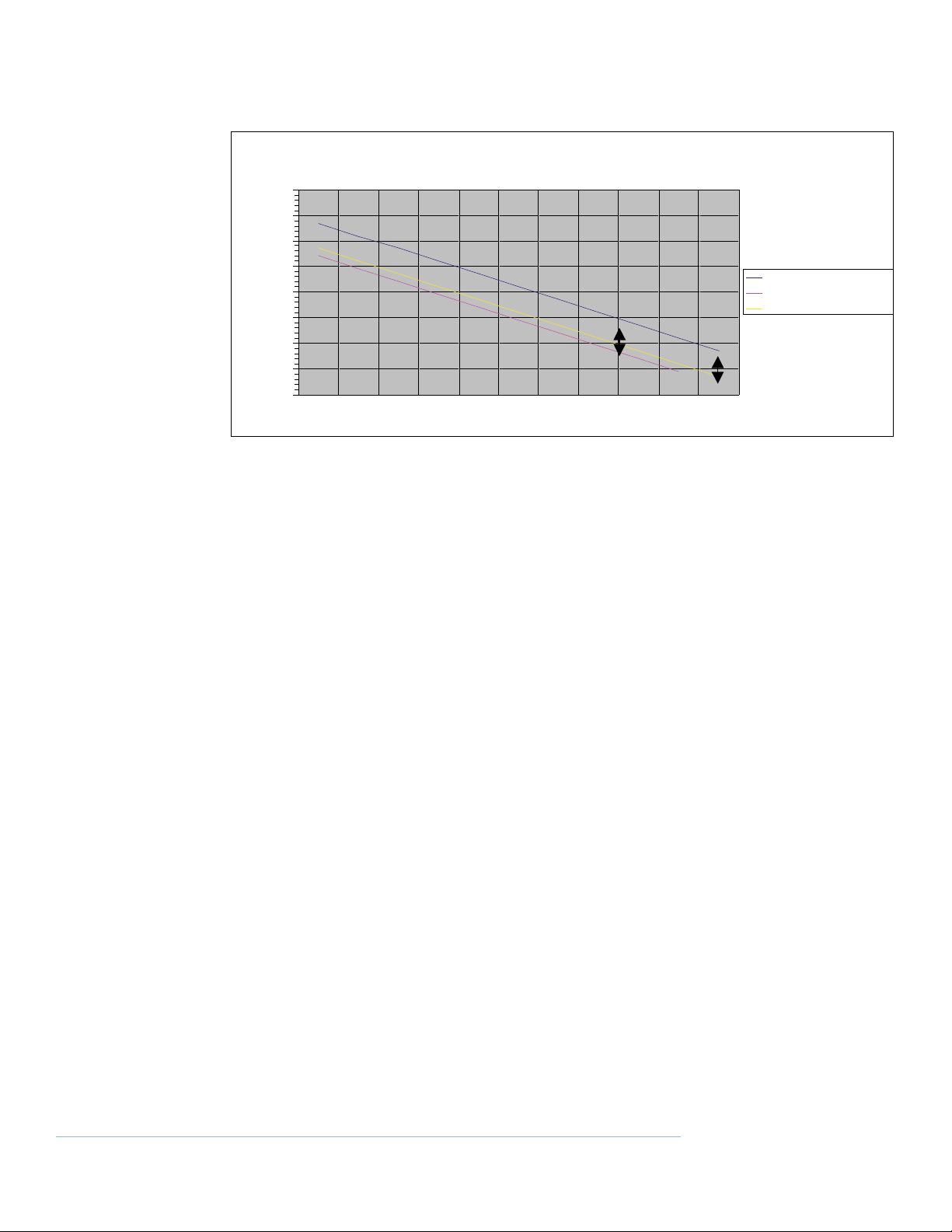
The following chart shows 1W and 2W measurement results compared with the result seen
on a 20W bench tester for the same component. There is only a 10 dB difference between PIM
measured at 2W and 20W. The arrows on the chart that follows indicate that a -153 dBc 2
Watt measurement is the equivalent to a -143 dBc at 20W.
Many tests have been performed and results show that a good rule of thumb is about 10 dB. It
should be noted that in certain circumstances the difference could be as much as 20 dB.
Users in the field have found that system components such as antennas and feeder cables
generally do fail PIM with an abrupt change in PIM performance and the 10 dB rule of thumb
holds. A measured PIM below -140 dBc (Green LED’s) is a passing component, while a component measuring PIM above -140 dBc (Red LED’s) indicated a problem. This allows identification
of problem components with the PIM 21, in spite of the lesser sensitivity.
*Model Dependent
9Boonton
Purpose, Function and Features
-80.00
-90.00
-100.00
-110.00
-120.00
-130.00
-140.00
-150.00
-160.00
PIM adjustment chart 1W & 2W vs 20W
20 Watt Ref PIM -dBc
1 Watt equivalent PIM -dBc
2Watt equivalent PIM -dBc
PIM Measurement
PIM comparison for different carrier powers
Functional Description
The PIM 21 generates two continuous wave carriers at up to 1W / 2W each*. These two carriers
are filtered and combined to a single common test port. The frequencies set in the PIM Test Set
depend on the type and can be customized. For references, please see the table in the addendum.
A receiver is also connected to the common test port via another filter. The receiver is tuned to
the 3rd order Intermodulation product of the two carriers for the measurement of PIM.
Receiver sensitivity is better than -123 dBm, typically -126 dBm.
Functional Block diagram
A microprocessor is used to monitor and control all active modules within the tester. Calibration tables are stored in non-volatile memory for all critical RF functions i.e. Rx calibration
parameters and excitation carrier power.
* Model Dependent
10 | PIM 21 User’s Manual

F1
Display
F2
Combiner
P
Test
Port
Rx
Ext
DC
Ext.DC
Fuse
DC
BATT
Fuse
int
DC
Batt
During the power up sequence all power supply rails (including battery and external DC supply)
are checked. Error messages or advisory messages, in the case of missing external DC, will be
displayed if voltage is outside of the limits.
Also during this sequence an RF calibration of the receiver module is performed using an internal noise source. This source is stable over a large temperature range and is used as a reference
to automatically adjust the receiver’s calibration if required.
RF carrier powers are constantly monitored when the RF is on, accurate closed loop power setting/control is achieved by comparing the actual carrier power with the stored calibration data
for each RF power detector.
Stable frequency reference is provided by a single 10 MHz crystal oscillator, this reference is
used for all RF frequency generation within the tester.
Power regulation is provided by switching converters for improved efficiency. The test set can
operate with an external DC source in the range of 10 to 16 volts DC. Correct battery charging is achievable over the same range of voltage through the use of a DC/DC converter in the
charging circuit.
11Boonton

Purpose, Function and Features
Two front panel fuses are provided for protection of the External DC input and battery circuits.
Reverse polarity protection is provided on the external DC input connection. Only in the case of
reverse connection a crowbar circuit will operate and the External DC input fuse will blow.
See parts list for fuse values to be used for replacement.
Features
The PIM 21 has a number of unique features that improve functionality and reliability.
• Battery powered with typically 1 hour of fully portable operation.
(Battery life will depend on number and duration of tests performed, 1 hour quoted is
for a fully charged battery with RF carrier power set to +30 dBm and operating continually).
• High efficiency design prolongs battery life and reduces heat generation.
• Battery can be charged fully from any external DC voltage source within 10 to 16
volts, which allows charging from a 12V vehicle supply using the provided connector.
(Standard negative ground vehicles only).
• Large LCD display and LED bar display for accurate and quick glance reading of result.
• Automatic RF calibration and voltage checking on power up.
• Adjustable RF carrier power from 100mW to 1W / 2W*.
• Compact design enables testing to be carried out in confined areas or on the antenna
mast.
• Selectable audible indications and external connections for remote monitoring.
• Selectable VSWR and PIM level alarms.
*Model dependent
12 | PIM 21 User’s Manual

Operation
Procedure
The PIM 21 has a number of user adjustable configuration settings and display/audio options.
This section covers the test set’s default settings only, see the advanced features and settings
section to make changes to defaults setting if required.
Standard “quick start” operating procedure.
NOTE: Before starting ensure nothing is connected to the Test Port. Calibration errors can occur
if external signals are present during the power up sequence.
1. Momentarily push the Green “PWR ON OFF” button.
2. LCD display will scroll through model, version and manufacturer’s details followed by licensing information for carrier frequencies installed, if applicable.
3. If “Batt Pwr Only” is displayed, check that the External DC input is connected and within
limits. If Battery operation is required press the “MENU” button to continue.
4. If any error messages are displayed during the startup sequence testing may still be carried out by pressing the “MENU” button to continue, but PIM measurements will be degraded.
Please note error message(s) and arrange for the unit to be serviced.
5. After the calibration cycle, the test set will enter the standby state displaying “RF OFF” on
the LCD.
6. At this point you are ready to start the recommended pre-test checks (see next section for
pre-test checks) or alternatively, directly start un-verified testing.
a) To start testing connect the component under test to the 7/16 TEST PORT via PIM
qualified interconnection cables and inter series adaptors (i.e. 7/16 (m) – N (f) supplied adaptor).
b) Ensure all ports of the test component are correctly terminated and/or radiating
components are shielded from personnel to reduce RF exposure. If the ‘REV PWR’ LED
indicator becomes lit during testing, the configuration should be rechecked. (See more
below).
7. Press either of the two red RF On/Off buttons to begin testing:
Pressing the ‘TIMED’ button will turn the two RF carriers on for a period of 30 seconds (default)
then returning to the Standby state.
Pressing the ‘CONT.’ button will turn the carriers on continuously until the ‘CONT.’ button is
pressed again.
13Boonton

Operational Procedure
Note that the red ‘RF ON’ LED will illuminate whenever the RF carriers are on.
If the ‘REV PWR’ LED indicator becomes lit during testing, first recheck test configuration for
correct terminations. The ‘REV PWR’ alarm has an initial delay of approximately 30 seconds
after ‘RF ON’ before entering an active state, all alarms following the delay are instantaneous.
NOTE: When turning the RF on for the first time after initial power up wait approximately 30
seconds for the carrier powers to settle prior to recording the PIM measurement. All subsequent RF on cycles do not require a 30 second pause prior to measurement.
8. Whenever the RF is ON the resultant PIM measurement will be automatically displayed on
the LCD. Results are displayed in a number of ways:
Numerically on the LCD in –dBc and as a bar graph.
Quick view LED bar graph which indicates green for PIM better than -140 dBc, and red for PIM
greater than -140 dBc.
Note that the LED scale is uncalibrated, and is intended for a quick view. Each LED represents
approximately a 2.7 dB change in PIM.
A PIM threshold alarm is also triggered whenever the PIM level exceeds -140 dBc (default),
this alarm is indicated on the red ‘PIM ALARM’ LED and as a dry contact closure on the ‘ALARM
OUT’ connector. (This may be set to other threshold values using the advanced SETUP routine
P.21-22)
14 | PIM 21 User’s Manual
The ‘PIM ALARM’ has an initial delay of approximately 30 seconds after ‘RF ON’ before entering
an active state, all alarms following the delay are instantaneous.

The third indicator of measurement results is through an audio tone. The tone varies in pitch
depending on the PIM level (default), the higher the pitch the higher the PIM level. Volume of
the tone is adjustable via the ‘TONE LEVEL’ control. If required, the tone can be connected to
external devices via the ‘TONE OUT’ connector.
9. After testing is complete the Test Set can be switched off by holding down the ‘PWR ON OFF’
switch for 5 or more seconds.
External
Pre-test Checks
In addition to the internal calibration that the tester performs on power up, another calibration
verification test can be performed externally prior to and post testing to confirm the integrity
of results.
1. Checking residual PIM levels using optional Low IM Load.
a) Connect the provided 7/16-N adaptor to the ‘TEST PORT’.
15Boonton

External Pre-test Checks
b) Connect one end of the provided low PIM cable to the adaptor on the Test Set and the
other to the Low PIM load.
c) Press either of the two red RF On/Off buttons to begin testing.
d) With this configuration the residual PIM should be ≤ -150 dBc and/or no more than
one of the green LED’s should light on the LED bar graph (true for any carrier power
set).
e) If levels are greater than the -150 dBc, check that all connectors are clean and firmly
hand tightened. Cables should also be inspected for damage. If levels are still greater
than -150 dBc, switch test set off and reinitiate the power up sequence. If it is still
high after this the test set and/or test accessories need servicing. (Note number is
negative, so -153 dBc is smaller!)
NOTE: When turning the RF on for the first time after initial power up wait approximately 30
seconds for the carrier powers to settle prior to recording the PIM measurement. All subsequent RF on cycles do not require a 30 second pause prior to measurement.
16 | PIM 21 User’s Manual

PIM Testing
Procedures
Accurate PIM testing relies on careful methodical processes and quality testing components.
Also, the operator must be aware of the sensitivities relating to carrier power and the expected
result. See Measurement Theory section for more detail.
Components
Choosing only PIM specified components for use in any test configuration is essential. The
most common source of PIM problems are connectors and how they interface to the cable.
The following connector/cable properties are a good starting point for accurate measurements.
Connector plating
Silver plating guarantees good results.
A close second to silver is a trimetal alloy known as white copper but also goes by a
number of trade names.
Never use Nickel plated or under plated connectors.
Connector Type
7/16 DIN, a reliable low PIM connector.
N, OK for low connection cycles must check regularly.
Low PIM Adaptors.
Avoid BNC, UHF, FME.
Cable Type
Solid outer corrugated, etc.
Solder soaked conformable.
Low PIM such as RG214 and RG223 with appropriate connectors.
Do NOT use foil types such as LMR400.
Other components will include Low PIM cable loads, but never use standard lumped attenuators type loads for low PIM testing.
Procedures
Always keep connector ends clean and damage free. Dropping a connector face down onto a
hard surface can nick the contact faces and degrade PIM performance.
Try to keep components used for PIM testing separate from general use components, this will
help to prolong their useful life.
Where possible tighten the connectors with a torque wrench.
During testing apply percussion and movement to cable assembles to ensure stability, vary the
severity to suit the intended application.
17Boonton

PIM Testing Procedures
Residual PIM Test
Before starting any test conduct a residual PIM test on the components which are to be used in
the test configuration.
This test makes use of the low PIM load as the standard termination for test cables, adaptors,
etc. Place all used components in series between the PIM test set and the low PIM load.
See “PRE TEST CHECKS” section for more details.
18 | PIM 21 User’s Manual
Antenna Testing
The testing of antennas for PIM needs special attention.
1. Most important, ensure personnel are not within the antenna aperture during the test
to reduce radiation exposure.
2. Antennas mounted on busy cellular sites may have significant signal powers coupled
from adjacent antennas. This may degrade the PIM results if these signals are close to
the Test Set receiver frequency. A quick test for this issue is to observe the Test Set’s
LED bar graph during standby state (RF OFF state), if there is any reading, some interference is present.
3. Be aware that the Test set generates two RF carriers. These carriers may cause interference to other services while testing.
4. Keep the testing time to a minimum when working with antennas.

5. Antennas are intentional radiators and can couple energy into other PIM generating
structures in close proximity. Depending on the level of PIM generation within the
adjacent structure the PIM can, in turn, also be received by the antenna and then be
measured by the Test Set. In this case it is difficult to know if it is the antenna at fault
or if the PIM is due to the environment around it.
Advanced Features
and Settings
The PIM 21 has a number of features and adjustable parameters to allow for customization
and differing test requirements.
The MENU key is used to scroll between 3 different menu items;
DISPLAY
SETUP
EXIT
After scrolling with the MENU key the desired topic is selected with the SELECT key. Selecting
escape will take you back to the previous menu.
A quick escape back to the default RF OFF display is to hold down the MENU key and press the
SELECT key until the display cycles through to RF OFF.
The UP DOWN keys are only used to increment the setting from within the SETUP menu.
Menu Structure
Start with default RF OFF display, then press MENU to reach either DISPLAY or SETUP:
From DISPLAY press SELECT, then press MENU to cycle through the following items:
1. Rx RSSI, Displays receiver sensitivity in dBm, typically -126 dBm*
2. PIM, Displays the units of measurement of PIM, in dBc
3. F1 Fwd PA Pwr, Displays the units of measurement for power of F1 as 0 dBm
4. F2 Fwd PA Pwr, Displays the units of measurement for power of F2 as 0 dBm
5. F1 Return Loss, Displays the units of measurement of F1 return loss as 0 dBm
6. F2 Return Loss, Displays the units of measurement of F2 return loss as 0 dBm
7. Battery Volts, Displays internal battery volts, 12 Volts*
8. Input Volts, (Ext DC) Displays battery volts being applied to EXT DC connector
9. 4.0 Volts (internal rail) Displays internal 4 Volt Rail, 4 Volts*
10. 5.0 Volts (internal rail) Displays internal 5 Volt Rail, 5 Volts*
EXIT, to return to default RF OFF hold MENU button down and press the SELECT key until the
display cycles through to RF OFF.
*If measurement deviates from this approximate value, call for service.
19Boonton

Advanced Features & Settings
For SETUP Mode:
From SETUP press SELECT, then press MENU to cycle through the following items:
1. Rev Pwr Alarm Sets threshold at which Reverse Power Alarm indicator and
output triggers, which alerts user to incorrect set up or termination.
2. PIM Alarm Level Sets threshold at which PIM Alarm indicator and output triggers, which provides user with alternate high PIM indications.
3. Tone Type Changes audio tone from Sliding to Beep using UP/DOWN
keys.
4. Tone Adj Adjusts frequency of tone to suit user using UP/DOWN keys.
5. Tx On time Adjusts the RF ‘on’ period for TIMED RF from 10 to 600 seconds in 10 second intervals using UP/DOWN keys.
6. Audible Threshold
EXIT, to return to default RF OFF hold MENU button down and press SELECT twice.
* Model Dependent
Default Settings
F1/F2 Power Lvl +33 dBm
Rev Pwr Alarm -12 dBm
PIM Alarm Level -140 dBc
Tone Type Sliding Tone
Tone Adj. 0
Tx On time. 30 Sec
External Connections
There are two connectors provided specifically for remote monitoring of the Test Set during
fault finding activities.
Intended to be connected to a simplex two way radio to enable an operator to be remote from
the tester but still hear activity if a PIM incident is disturbed on the line under test.
Connector 1: ALARM OUT 2.5 mm stereo phone jack
A dry contact closure between the tip and ring of this connector when the PIM threshold is
exceeded. Typically connected to the PTT (Push To Talk) of a two way radio.
Connector 2: TONE OUT 3.5 mm stereo phone jack
Low level tone output prior to speaker driver amplifier, tone level control controls level to this
port. Audio is available on the tip and ring (ring is also connected to ground) of the connector.
20 | PIM 21 User’s Manual
Typically connected to the MIC input of the two way radio, output is DC isolated.

Maintenance and
Support
Support
The PIM 21 PIM Test Set carries a warranty of 12 months after date of delivery, covering parts
and labor manufacturing defects, but not against any mistreatment. The warranty excludes
scheduled calibration, test cables, adaptors and low IM loads.
If service is required the total unit is to be returned to Boonton for service by qualified service
personnel.
Recommended battery replacement:
Every 18 months or as required.
Recommended calibration period:
Every 12 months or following service.
For general enquires and repair details please e-mail:
service@boonton.com
Wireless Telecom Group Inc.
Parsippany, NJ 07054
USA
Tel: +1 973 386 9696
Fax: +1 973 386 9191
boonton@boonton.com
www.boonton.com
Wireless Telecom Group
Cheadle Hulme, Cheshire
United Kingdom
Tel: +44 (0) 161 486 3353
Fax: +44 (0) 161 486 3354
Wireless Telecom Group
Roissy
France
Tel: +33 (0) 1 72 02 30 30
Fax: +33 (0) 1 49 38 01 06
Wireless Telecom Group
Ismaning
Germany
Tel: +49 (0) 89 996 41 0
Fax: +49 (0) 89 996 41 440
Wireless Telecom Group.
Singapore
Tel: +65 6827 9670
Fax: +65 6827 9601
Wireless Telecom Group
Shanghai
China
Tel: +86 21 5835 5718
Fax: +86 21 5835 5238
21Boonton

Specifications
Specifications
Measurement type: Single port reflection PIM measurement.
Carrier Power
Cellular +20 to +33 dBm, in 1dB steps
PCS +20 to +30 dBm, in 1dB steps
Power accuracy: ± 1 dB / carrier
Carrier frequencies*: Depending on type
Measurement frequency*: Depending on type
Measurement range: -80 dBc to -150 dBc, typically to -155 dBc
Measurement accuracy: ± 2 dB to -153 dBc
± 3 dB to -155 dBc
Frequency accuracy: ± 2 p.p.m., 0 to 50°C
Measurement displays 3 digit numeric backlit, 16 x 2, LCD display,
16 LED bar graph, (transition green to red at -140 dBc)
and variable tone audio
VSWR measurement: LCD and LED Alarm,
Trigger adjustable from -6 to -16 dB Return Loss.
VSWR measurement: < 12 dB Return Loss ± 3 dB
Accuracy > 12dB calculated indication only
External interface(s): ON/OFF contacts for PIM alarm (adjustable) and audio tone
output. 2.5 mm and 3.5 mm stereo phone sockets.
Measurement connector: 7/16 mm DIN Female
Power requirement: External DC input 10 to16 V @ 3.5 Amps max
Internal Battery: Sealed Lead Acid, 1 hour continuous operation
(with +30 dBm carriers)
Charging Time: 4 to 5 Hours. No damage for continuous charging.
Weight: < 8 kg (17.6 lbs) nominal.
Dimensions, L x W x D: 34.3 x 32.7 x 15.2 cm (13.5 x 12.9 x 6.0 inches)
Enclosure: Weather-proof PelicanTM 1400 case.
Operating Temp: 0 to 45°C / 10 ~ 85 % humidity, (non condensing)
Storage Temp: -10 to 60°C / 10 ~ 85 % humidity, (non condensing)
IP rating: IP55 Lid closed (storage) and
IP40 lid open (operational).
*Frequencies will be customized. For additional information see also table in the addendum.
22 | PIM 21 User’s Manual

Types & Frequencies
Type F1 F2 IM31
GK-A01 869 891.5 846.5
GK-A02 1945 1989.7 1900.3
GK-A04 947.6 960 935.2
GK-A05 935 960 910
GK-A06 1940 1980 1900
GK-A07 2125 2140 2110
GK-A08 1855 1930 1780
GK-A09 835 875 795
Other frequencies available on request.
Version Control
Revision Comments Date Approved
1 First release ML-736 (PIM 20) 10/29/07 AR
2 Updated to reflect improvements in location
of DC Input and fuses 12/07/07 AR
3 Added type & frequency table 2/7/2008 WD
4 Update output power & Model Numbers 10/10/2008 AS
5 Update PIM 21 1/30/2010 AS
23Boonton

Addendum - Data Acquisition Software
1 Introduction . . . . . . . . . . . . . . . . . . . . . . . . . . . . . . . . . . . . . . . . . . . . . . . 25
1.1 Abstract . . . . . . . . . . . . . . . . . . . . . . . . . . . . . . . . . . . . . . . . . . . . . . . . . 25
1.2 Required Software . . . . . . . . . . . . . . . . . . . . . . . . . . . . . . . . . . . . . . . . 25
1.3 Prerequisites . . . . . . . . . . . . . . . . . . . . . . . . . . . . . . . . . . . . . . . . . . . . . 25
2 Installation . . . . . . . . . . . . . . . . . . . . . . . . . . . . . . . . . . . . . . . . . . . . . . . . 26
2.1 USB Flash Drive . . . . . . . . . . . . . . . . . . . . . . . . . . . . . . . . . . . . . . . . . . . 26
Data Acquisition Software
Installation Notes
2.2 Installing the prerequisite Add-In . . . . . . . . . . . . . . . . . . . . . . . . . . . 30
2.3 Manual start from USB Flash Drive . . . . . . . . . . . . . . . . . . . . . . . . . . 31
2.4 FTP Download . . . . . . . . . . . . . . . . . . . . . . . . . . . . . . . . . . . . . . . . . . . . 31
Table of Figures
Figure 1 - Boonton Software . . . . . . . . . . . . . . . . . . . . . . . . . . . . . . . . . . . . . . 26
Figure 2 - PIMT Data Acq. . . . . . . . . . . . . . . . . . . . . . . . . . . . . . . . . . . . . . . . . . 26
Figure 3 - ‘Welcome’ dialog box . . . . . . . . . . . . . . . . . . . . . . . . . . . . . . . . . . . 27
Figure 4 - License Agreement . . . . . . . . . . . . . . . . . . . . . . . . . . . . . . . . . . . . . 27
Figure 5 - Installation Folder . . . . . . . . . . . . . . . . . . . . . . . . . . . . . . . . . . . . . . 28
Figure 6 - Confirm Installation . . . . . . . . . . . . . . . . . . . . . . . . . . . . . . . . . . . . . 28
Figure 7 – Installation Complete . . . . . . . . . . . . . . . . . . . . . . . . . . . . . . . . . . . 29
Figure 8 - EULA . . . . . . . . . . . . . . . . . . . . . . . . . . . . . . . . . . . . . . . . . . . . . . . . . . 30
Figure 9 - Add-In Installation complete . . . . . . . . . . . . . . . . . . . . . . . . . . . . . 30
24 | PIM 21 User’s Manual

1 Introduction
1.1 Abstract
The Passive Inter-Modulation Tester Data Acquisition software is a Microsoft Windows based
application used to log data and publish PIM measurements to a file in the PDF format. The
data is ‘pulled’ from the PIMT unit using a RS-232 connection.
1.2 Required Software
Wireless Telecom Group supplies a USB flash drive that contains all the files necessary for automatic installation. An ftp web site is also available to download the software if the Wireless
Telecom Group flash drive is unavailable.
1.3 Prerequisites
The PIMT Data Acquisition software uses Microsoft Excel as a container for the measurement
data and uses its publishing capabilities to generate the PDF files. Earlier versions of Excel
require an Add-In to enhance its capabilities so as to create PDF format files. The installation procedure will check for this Add-In, and if not detected, prompt the user to continue the
installation.
25Boonton

Addendum - Data Acquisition Software
2 Installation
2.1 USB Flash Drive
1) Insert the flash drive containing the installation software into the USB port on the computer. The “Boonton Software” popup dialog box should appear. (Figure 1 – Boonton software)
Select the item: “Install Boonton PIMT Software using the program provided on the device”.
Click “OK”. If this dialog fails to appear, proceed to Manual start from USB Flash Drive
Figure 1 - Boonton Software
The Windows installer will start. (Figure 2 – ‘Welcome’ dialog box) Click ‘Next’ to proceed with
the installation. If the Add-In dialog box appears (Figure 3 - PIMT Data Acq.), proceed to step
Installing the prerequisite Add-In.
Figure 2 - PIMT Data Acq.
26 | PIM 21 User’s Manual

Figure 3 - ‘Welcome’ dialog box
2) Click ‘Next’ to continue.
Figure 4 - License Agreement
3) Read the software license agreement and click “I Agree” and then ‘Next’ to continue with
the installation.
27Boonton

Addendum - Data Acquisition Software
Figure 5 - Installation Folder
4) Accept the default installation folder by clicking ‘Next’.
Figure 6 - Confirm Installation
28 | PIM 21 User’s Manual
5) Click ‘Next’ to begin the installation

Figure 7 – Installation Complete
6) Click ‘Close’ to complete the installation.
This completes the installation. A shortcut is created on the desktop for the PIMT Data Acq. application. Double click this shortcut to start the using the data logging application.
29Boonton

Addendum - Data Acquisition Software
2.2 Installing the prerequisite Add-In
1) If the Add-In dialog box appears (Figure 3 - PIMT Data Acq.), click ‘Yes’ to install the required Add-In.
2) Click to accept the license terms and press ‘Continue’ (Figure 9 – EULA)
Figure 8 - EULA
30 | PIM 21 User’s Manual
3) When the installation completes, click ‘OK’
Figure 9 - Add-In Installation complete
4) At this point, only the Add-In has been installed. Remove the USB flash drive and proceed
with installation from: USB Flash Drive

2.3 Manual start from USB Flash Drive
Some computers have the auto start capability disabled so the “Boonton Software” popup
dialog box (Figure 1 - Boonton Software) doesn’t appear. If this is the case, open an Explorer
window and locate the Wireless Telecom Group removable flash drives root directory. Double
click on the ‘setup.exe’ file and continue the installation from: USB Flash Drive.
2.4 FTP Download
The Passive Inter-Modulation Tester Data Acquisition software is available for FTP transfer at:
ftp://pimware:dloadz!@72.165.246.11/Data/pimware
Right click on the folder named: PIMT_Data_Acq_x.y (where x.y is the version) and save the
contents of this folder to a USB flash drive or a temporary directory on your computers disk
drive. Follow the instructions: USB Flash Drive
31Boonton
 Loading...